EP3767089B1 - Motor - Google Patents
Motor Download PDFInfo
- Publication number
- EP3767089B1 EP3767089B1 EP19768663.7A EP19768663A EP3767089B1 EP 3767089 B1 EP3767089 B1 EP 3767089B1 EP 19768663 A EP19768663 A EP 19768663A EP 3767089 B1 EP3767089 B1 EP 3767089B1
- Authority
- EP
- European Patent Office
- Prior art keywords
- hydraulic
- chamber
- hydraulic chamber
- piston
- combustion
- Prior art date
- Legal status (The legal status is an assumption and is not a legal conclusion. Google has not performed a legal analysis and makes no representation as to the accuracy of the status listed.)
- Active
Links
Images


Classifications
-
- F—MECHANICAL ENGINEERING; LIGHTING; HEATING; WEAPONS; BLASTING
- F02—COMBUSTION ENGINES; HOT-GAS OR COMBUSTION-PRODUCT ENGINE PLANTS
- F02B—INTERNAL-COMBUSTION PISTON ENGINES; COMBUSTION ENGINES IN GENERAL
- F02B75/00—Other engines
- F02B75/04—Engines with variable distances between pistons at top dead-centre positions and cylinder heads
- F02B75/044—Engines with variable distances between pistons at top dead-centre positions and cylinder heads by means of an adjustable piston length
-
- F—MECHANICAL ENGINEERING; LIGHTING; HEATING; WEAPONS; BLASTING
- F02—COMBUSTION ENGINES; HOT-GAS OR COMBUSTION-PRODUCT ENGINE PLANTS
- F02B—INTERNAL-COMBUSTION PISTON ENGINES; COMBUSTION ENGINES IN GENERAL
- F02B75/00—Other engines
- F02B75/04—Engines with variable distances between pistons at top dead-centre positions and cylinder heads
-
- F—MECHANICAL ENGINEERING; LIGHTING; HEATING; WEAPONS; BLASTING
- F02—COMBUSTION ENGINES; HOT-GAS OR COMBUSTION-PRODUCT ENGINE PLANTS
- F02M—SUPPLYING COMBUSTION ENGINES IN GENERAL WITH COMBUSTIBLE MIXTURES OR CONSTITUENTS THEREOF
- F02M57/00—Fuel-injectors combined or associated with other devices
- F02M57/02—Injectors structurally combined with fuel-injection pumps
- F02M57/022—Injectors structurally combined with fuel-injection pumps characterised by the pump drive
- F02M57/025—Injectors structurally combined with fuel-injection pumps characterised by the pump drive hydraulic, e.g. with pressure amplification
-
- F—MECHANICAL ENGINEERING; LIGHTING; HEATING; WEAPONS; BLASTING
- F01—MACHINES OR ENGINES IN GENERAL; ENGINE PLANTS IN GENERAL; STEAM ENGINES
- F01B—MACHINES OR ENGINES, IN GENERAL OR OF POSITIVE-DISPLACEMENT TYPE, e.g. STEAM ENGINES
- F01B17/00—Reciprocating-piston machines or engines characterised by use of uniflow principle
- F01B17/02—Engines
-
- F—MECHANICAL ENGINEERING; LIGHTING; HEATING; WEAPONS; BLASTING
- F01—MACHINES OR ENGINES IN GENERAL; ENGINE PLANTS IN GENERAL; STEAM ENGINES
- F01B—MACHINES OR ENGINES, IN GENERAL OR OF POSITIVE-DISPLACEMENT TYPE, e.g. STEAM ENGINES
- F01B9/00—Reciprocating-piston machines or engines characterised by connections between pistons and main shafts, not specific to groups F01B1/00 - F01B7/00
- F01B9/02—Reciprocating-piston machines or engines characterised by connections between pistons and main shafts, not specific to groups F01B1/00 - F01B7/00 with crankshaft
- F01B9/026—Rigid connections between piston and rod; Oscillating pistons
-
- F—MECHANICAL ENGINEERING; LIGHTING; HEATING; WEAPONS; BLASTING
- F02—COMBUSTION ENGINES; HOT-GAS OR COMBUSTION-PRODUCT ENGINE PLANTS
- F02B—INTERNAL-COMBUSTION PISTON ENGINES; COMBUSTION ENGINES IN GENERAL
- F02B75/00—Other engines
- F02B75/32—Engines characterised by connections between pistons and main shafts and not specific to preceding main groups
-
- F—MECHANICAL ENGINEERING; LIGHTING; HEATING; WEAPONS; BLASTING
- F02—COMBUSTION ENGINES; HOT-GAS OR COMBUSTION-PRODUCT ENGINE PLANTS
- F02D—CONTROLLING COMBUSTION ENGINES
- F02D15/00—Varying compression ratio
- F02D15/02—Varying compression ratio by alteration or displacement of piston stroke
-
- F—MECHANICAL ENGINEERING; LIGHTING; HEATING; WEAPONS; BLASTING
- F02—COMBUSTION ENGINES; HOT-GAS OR COMBUSTION-PRODUCT ENGINE PLANTS
- F02M—SUPPLYING COMBUSTION ENGINES IN GENERAL WITH COMBUSTIBLE MIXTURES OR CONSTITUENTS THEREOF
- F02M59/00—Pumps specially adapted for fuel-injection and not provided for in groups F02M39/00 -F02M57/00, e.g. rotary cylinder-block type of pumps
- F02M59/02—Pumps specially adapted for fuel-injection and not provided for in groups F02M39/00 -F02M57/00, e.g. rotary cylinder-block type of pumps of reciprocating-piston or reciprocating-cylinder type
- F02M59/10—Pumps specially adapted for fuel-injection and not provided for in groups F02M39/00 -F02M57/00, e.g. rotary cylinder-block type of pumps of reciprocating-piston or reciprocating-cylinder type characterised by the piston-drive
- F02M59/105—Pumps specially adapted for fuel-injection and not provided for in groups F02M39/00 -F02M57/00, e.g. rotary cylinder-block type of pumps of reciprocating-piston or reciprocating-cylinder type characterised by the piston-drive hydraulic drive
-
- F—MECHANICAL ENGINEERING; LIGHTING; HEATING; WEAPONS; BLASTING
- F16—ENGINEERING ELEMENTS AND UNITS; GENERAL MEASURES FOR PRODUCING AND MAINTAINING EFFECTIVE FUNCTIONING OF MACHINES OR INSTALLATIONS; THERMAL INSULATION IN GENERAL
- F16C—SHAFTS; FLEXIBLE SHAFTS; ELEMENTS OR CRANKSHAFT MECHANISMS; ROTARY BODIES OTHER THAN GEARING ELEMENTS; BEARINGS
- F16C7/00—Connecting-rods or like links pivoted at both ends; Construction of connecting-rod heads
- F16C7/04—Connecting-rods or like links pivoted at both ends; Construction of connecting-rod heads with elastic intermediate part of fluid cushion
-
- F—MECHANICAL ENGINEERING; LIGHTING; HEATING; WEAPONS; BLASTING
- F16—ENGINEERING ELEMENTS AND UNITS; GENERAL MEASURES FOR PRODUCING AND MAINTAINING EFFECTIVE FUNCTIONING OF MACHINES OR INSTALLATIONS; THERMAL INSULATION IN GENERAL
- F16C—SHAFTS; FLEXIBLE SHAFTS; ELEMENTS OR CRANKSHAFT MECHANISMS; ROTARY BODIES OTHER THAN GEARING ELEMENTS; BEARINGS
- F16C7/00—Connecting-rods or like links pivoted at both ends; Construction of connecting-rod heads
- F16C7/06—Adjustable connecting-rods
-
- F—MECHANICAL ENGINEERING; LIGHTING; HEATING; WEAPONS; BLASTING
- F02—COMBUSTION ENGINES; HOT-GAS OR COMBUSTION-PRODUCT ENGINE PLANTS
- F02B—INTERNAL-COMBUSTION PISTON ENGINES; COMBUSTION ENGINES IN GENERAL
- F02B75/00—Other engines
- F02B75/02—Engines characterised by their cycles, e.g. six-stroke
- F02B2075/022—Engines characterised by their cycles, e.g. six-stroke having less than six strokes per cycle
- F02B2075/025—Engines characterised by their cycles, e.g. six-stroke having less than six strokes per cycle two
-
- F—MECHANICAL ENGINEERING; LIGHTING; HEATING; WEAPONS; BLASTING
- F02—COMBUSTION ENGINES; HOT-GAS OR COMBUSTION-PRODUCT ENGINE PLANTS
- F02B—INTERNAL-COMBUSTION PISTON ENGINES; COMBUSTION ENGINES IN GENERAL
- F02B25/00—Engines characterised by using fresh charge for scavenging cylinders
- F02B25/02—Engines characterised by using fresh charge for scavenging cylinders using unidirectional scavenging
- F02B25/04—Engines having ports both in cylinder head and in cylinder wall near bottom of piston stroke
-
- F—MECHANICAL ENGINEERING; LIGHTING; HEATING; WEAPONS; BLASTING
- F02—COMBUSTION ENGINES; HOT-GAS OR COMBUSTION-PRODUCT ENGINE PLANTS
- F02B—INTERNAL-COMBUSTION PISTON ENGINES; COMBUSTION ENGINES IN GENERAL
- F02B3/00—Engines characterised by air compression and subsequent fuel addition
- F02B3/06—Engines characterised by air compression and subsequent fuel addition with compression ignition
-
- F—MECHANICAL ENGINEERING; LIGHTING; HEATING; WEAPONS; BLASTING
- F02—COMBUSTION ENGINES; HOT-GAS OR COMBUSTION-PRODUCT ENGINE PLANTS
- F02M—SUPPLYING COMBUSTION ENGINES IN GENERAL WITH COMBUSTIBLE MIXTURES OR CONSTITUENTS THEREOF
- F02M47/00—Fuel-injection apparatus operated cyclically with fuel-injection valves actuated by fluid pressure
- F02M47/02—Fuel-injection apparatus operated cyclically with fuel-injection valves actuated by fluid pressure of accumulator-injector type, i.e. having fuel pressure of accumulator tending to open, and fuel pressure in other chamber tending to close, injection valves and having means for periodically releasing that closing pressure
- F02M47/027—Electrically actuated valves draining the chamber to release the closing pressure
-
- F—MECHANICAL ENGINEERING; LIGHTING; HEATING; WEAPONS; BLASTING
- F02—COMBUSTION ENGINES; HOT-GAS OR COMBUSTION-PRODUCT ENGINE PLANTS
- F02M—SUPPLYING COMBUSTION ENGINES IN GENERAL WITH COMBUSTIBLE MIXTURES OR CONSTITUENTS THEREOF
- F02M59/00—Pumps specially adapted for fuel-injection and not provided for in groups F02M39/00 -F02M57/00, e.g. rotary cylinder-block type of pumps
- F02M59/44—Details, components parts, or accessories not provided for in, or of interest apart from, the apparatus of groups F02M59/02 - F02M59/42; Pumps having transducers, e.g. to measure displacement of pump rack or piston
- F02M59/46—Valves
- F02M59/466—Electrically operated valves, e.g. using electromagnetic or piezoelectric operating means
-
- Y—GENERAL TAGGING OF NEW TECHNOLOGICAL DEVELOPMENTS; GENERAL TAGGING OF CROSS-SECTIONAL TECHNOLOGIES SPANNING OVER SEVERAL SECTIONS OF THE IPC; TECHNICAL SUBJECTS COVERED BY FORMER USPC CROSS-REFERENCE ART COLLECTIONS [XRACs] AND DIGESTS
- Y02—TECHNOLOGIES OR APPLICATIONS FOR MITIGATION OR ADAPTATION AGAINST CLIMATE CHANGE
- Y02T—CLIMATE CHANGE MITIGATION TECHNOLOGIES RELATED TO TRANSPORTATION
- Y02T10/00—Road transport of goods or passengers
- Y02T10/10—Internal combustion engine [ICE] based vehicles
- Y02T10/12—Improving ICE efficiencies
Definitions
- An engine of a crosshead type is sometimes used as a marine engine.
- a sliding portion is arranged in a crosshead, and actuation of the sliding portion by hydraulic pressure causes a top dead center position of the piston to move.
- a geometrical compression ratio of the engine can be changed.
- Patent Literature 2 discloses an engine according to the preamble of claim 1.
- Patent Literature 4 to 7 disclose further prior art.
- the present disclosure has an object to provide an engine capable of suppressing an increase in complexity of structure.
- FIG. 1 is an explanatory view for illustrating an overall configuration of an engine 100.
- the engine 100 includes a cylinder 110, a piston 112, a piston rod 114, a crosshead 116, a connecting rod 118, a crankshaft 120, a flywheel 122, a cylinder cover 124, an exhaust valve cage 126, a combustion chamber 128, an exhaust valve 130, an exhaust valve drive device 132, an exhaust pipe 134, a scavenge reservoir 136, a cooler 138, a cylinder jacket 140, and a fuel injection valve 142.
- the piston 112 is provided inside the cylinder 110.
- the piston 112 reciprocates inside the cylinder 110.
- One end of the piston rod 114 is attached to the piston 112.
- a crosshead pin 150 of the crosshead 116 is coupled to another end of the piston rod 114.
- the crosshead 116 reciprocates together with the piston 112.
- a movement of the crosshead 116 in a right-and-left direction (direction perpendicular to a stroke direction of the piston 112) in FIG. 1 is regulated by a guide shoe 116a.
- the crosshead pin 150 is axially supported by a crosshead bearing 118a provided at one end of the connecting rod 118.
- the crosshead pin 150 supports one end of the connecting rod 118.
- the another end of the piston rod 114 and the one end of the connecting rod 118 are connected to each other through an intermediation of the crosshead 116.
- crankshaft 120 Another end of the connecting rod 118 is coupled to the crankshaft 120.
- the crankshaft 120 is rotatable with respect to the connecting rod 118.
- the crankshaft 120 rotates.
- the flywheel 122 is mounted to the crankshaft 120. Rotations of the crankshaft 120 and the like are stabilized by inertia of the flywheel 122.
- the cylinder cover 124 is provided at a top end of the cylinder 110.
- the exhaust valve cage 126 is inserted through the cylinder cover 124.
- One end of the exhaust valve cage 126 faces the piston 112.
- An exhaust port 126a is opened in the one end of the exhaust valve cage 126.
- the exhaust port 126a is opened to the combustion chamber 128.
- the combustion chamber 128 faces a crown surface of the piston 112.
- the combustion chamber 128 is formed inside the cylinder 110 so as to be surrounded by the cylinder cover 124, the cylinder 110, and the piston 112.
- a valve body of the exhaust valve 130 is located in the combustion chamber 128.
- the exhaust valve drive device 132 is attached to a rod portion of the exhaust valve 130.
- the exhaust valve drive device 132 is arranged in the exhaust valve cage 126.
- the exhaust valve drive device 132 moves the exhaust valve 130 in the stroke direction of the piston 112.
- the exhaust pipe 134 is attached to the exhaust valve cage 126 and a turbocharger C.
- An inside of the exhaust pipe 134 communicates with the exhaust port 126a and a turbine of the turbocharger C.
- the exhaust gas discharged from the exhaust port 126a is supplied to the turbine (not shown) of the turbocharger C through the exhaust pipe 134, and is then discharged to the outside.
- active gas is pressurized by a compressor (not shown) of the turbocharger C.
- the active gas is, for example, air.
- the pressurized active gas is cooled by the cooler 138 in the scavenge reservoir 136.
- a bottom end of the cylinder 110 is surrounded by the cylinder jacket 140.
- a scavenge chamber 140a is formed inside the cylinder jacket 140. The active gas after the cooling is forcibly fed into the scavenge chamber 140a.
- Scavenging ports 110a are formed on a bottom end side of the cylinder 110.
- the scavenging port 110a is a hole passing from an inner peripheral surface to an outer peripheral surface of the cylinder 110.
- a plurality of scavenging ports 110a are formed at intervals in a circumferential direction of the cylinder 110.
- the fuel injection valve 142 is provided in the cylinder cover 124. A distal end of the fuel injection valve 142 is directed toward the combustion chamber 128 side.
- the fuel injection valve 142 injects a liquid fuel (fuel oil) into the combustion chamber 128.
- the liquid fuel is combusted, and expansion pressure generated by the combustion causes the piston 112 to reciprocate.
- FIG. 2 is an extracted view for illustrating a coupling portion between the piston rod 114 and the crosshead pin 150.
- a flat surface portion 152 is formed on an outer peripheral surface on the piston 112 side of the crosshead pin 150.
- the flat surface portion 152 extends in a direction substantially perpendicular to the stroke direction of the piston 112.
- a pin hole (large-diameter hole) 154 is formed in the crosshead pin 150.
- the pin hole 154 is opened in the flat surface portion 152.
- the pin hole 154 extends from the flat surface portion 152 toward the crankshaft 120 side (lower side in FIG. 2 ) along the stroke direction.
- a cover member 160 is provided on the flat surface portion 152 of the crosshead pin 150.
- the cover member 160 is attached to the flat surface portion 152 of the crosshead pin 150 by a fastening member 162.
- the cover member 160 covers the pin hole 154.
- a cover hole 160a passing in the stroke direction is formed in the cover member 160.
- the piston rod 114 includes a large-diameter portion (sliding portion) 114a and a small-diameter portion 114b.
- An outer diameter of the large-diameter portion 114a is larger than an outer diameter of the small-diameter portion 114b.
- the large-diameter portion 114a is formed at the another end of the piston rod 114.
- the large-diameter portion 114a is inserted into (accommodated in) the pin hole 154 of the crosshead pin 150.
- the small-diameter portion 114b is formed at the one end side of the piston rod 114 with respect to the large-diameter portion 114a.
- the small-diameter portion 114b is inserted into the cover hole 160a of the cover member 160.
- a hydraulic chamber 154a is formed inside the pin hole 154.
- the pin hole 154 is partitioned by the large-diameter portion 114a in the stroke direction.
- the large-diameter portion 114a is located on a top dead center position side of the piston 112 in the hydraulic chamber 154a.
- the hydraulic chamber 154a is a space defined on a bottom surface 154b side of the pin hole 154 partitioned by the large-diameter portion 114a.
- a hydraulic surface 114a 1 of the large-diameter portion 114a facing a side (lower side of FIG. 2 ) opposite to the combustion chamber 128 faces the hydraulic chamber 154a and a bottom surface 154b of the pin hole 154.
- the hydraulic chamber 154a is formed between the hydraulic surface 114a 1 and the bottom surface 154b.
- a side wall of the hydraulic chamber 154a (that is, a side wall 154c of the pin hole 154) extends in the stroke direction.
- One end of an oil passage 156 is opened in the bottom surface 154b of the pin hole 154.
- Another end of the oil passage 156 is opened to an outside of the crosshead pin 150.
- a hydraulic pipe 170 is connected to the another end of the oil passage 156.
- a hydraulic pump 172 communicates with the hydraulic pipe 170. That is, the hydraulic pump 172 is connected to the hydraulic chamber 154a.
- a check valve 174 is provided between the hydraulic pump 172 and the oil passage 156. A flow of working oil flowing from the oil passage 156 side toward the hydraulic pump 172 side is suppressed by the check valve 174. The working oil is forcibly fed (delivered) into the hydraulic chamber 154a from the hydraulic pump 172 through the oil passage 156.
- a branch pipe 176 is connected to the hydraulic pipe 170 between the oil passage 156 and the check valve 174.
- a selector valve 178 is provided to the branch pipe 176.
- the selector valve 178 is, for example, an electromagnetic valve.
- the selector valve 178 is closed during an operation of the hydraulic pump 172.
- the selector valve 178 communicates with an oil tank (not shown) on a side opposite to the oil passage 156. The discharged working oil is retained in the oil tank.
- the oil tank supplies the working oil to the hydraulic pump 172.
- the large-diameter portion 114a slides on an inner peripheral surface of the pin hole 154 in the stroke direction in accordance with an oil amount of the working oil in the hydraulic chamber 154a.
- the large-diameter portion 114a slides with respect to the side wall 154c in accordance with an amount of the working oil in the hydraulic chamber 154a.
- the piston rod 114 moves in the stroke direction.
- the piston 112 moves (performs a stroke motion) together with the piston rod 114 (large-diameter portion 114a).
- the top dead center position of the piston 112 moves toward the combustion chamber 128 side.
- the top dead center position of the piston 112 moves toward the bottom dead center position side.
- the top dead center position of the piston 112 becomes changeable.
- the engine 100 includes a compression ratio changing mechanism V.
- the compression ratio changing mechanism V includes the hydraulic chamber 154a and the large-diameter portion 114a of the piston rod 114 described above.
- the compression ratio changing mechanism V moves the top dead center position of the piston 112 so that the compression ratio is changeable.
- a space 154d on the cover member 160 side of the pin hole 154 partitioned by the large-diameter portion 114a may also be a hydraulic chamber.
- This hydraulic chamber may be used together with the hydraulic chamber 154a or may be used individually.
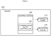
- FIG. 3 is a functional block diagram for illustrating the engine 100.
- the engine 100 includes a control device 180.
- the control device 180 is formed of, for example, an engine controller (ECU).
- the control device 180 is formed of a central processing unit (CPU), a ROM storing programs and the like, a RAM serving as a work area, and the like, and is configured to control the entire engine 100.
- the control device 180 functions as a compression ratio controller 182.
- the compression ratio controller 182 is configured to control the hydraulic pump 172 and the selector valve 178 to change (move) the top dead center position of the piston 112. In such a manner, the compression ratio controller 182 controls a geometrical compression ratio of the engine 100.
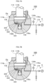
- FIG. 4A and FIG. 4B are views for illustrating a combustion pressure suppression mechanism P.
- FIG. 4A and FIG. 4B are extracted views for illustrating the same portion as that of FIG. 2 .
- the engine 100 includes the combustion pressure suppression mechanism P.
- the combustion pressure suppression mechanism P includes the above-mentioned hydraulic chamber 154a, a small-diameter hole 158, a partition piston 164, and an elastic member 166.
- the small-diameter hole 158 is opened in the bottom surface 154b of the pin hole 154.
- the small-diameter hole 158 continuously extends from the hydraulic chamber 154a of the pin hole 154 in the stroke direction. That is, a side wall 158a of the small-diameter hole 158 extends in the stroke direction.
- An inner diameter of the small-diameter hole 158 is smaller than an inner diameter of the pin hole 154 (hydraulic chamber 154a).
- the partition piston 164 is provided in the small-diameter hole 158 so as to be slidable.
- the partition piston 164 partitions the small-diameter hole 158 into an auxiliary hydraulic chamber 158b and an accommodation chamber 158c.
- the auxiliary hydraulic chamber 158b is located on the hydraulic chamber 154a side with respect to the partition piston 164.
- the accommodation chamber 158c is located on a side away from the hydraulic chamber 154a with respect to the partition piston 164.
- the auxiliary hydraulic chamber 158b is continuous with the hydraulic chamber 154a. A part of the working oil supplied to the hydraulic chamber 154a flows into the auxiliary hydraulic chamber 158b.
- the partition piston 164 is pressed toward the accommodation chamber 158c side by the hydraulic pressure of the working oil.
- the elastic member 166 is arranged in the accommodation chamber 158c.
- the elastic member 166 is formed of, for example, an elastic spring.
- the elastic member 166 presses the partition piston 164 from the accommodation chamber 158c side toward the auxiliary hydraulic chamber 158b side (hydraulic chamber 154a side or piston rod 114 side) against the hydraulic pressure of the working oil.
- the volume of the auxiliary hydraulic chamber 158b increases.
- the volume of the auxiliary hydraulic chamber 158b changes in accordance with the hydraulic pressure inside. Accordingly, the working oil flows from the hydraulic chamber 154a into the auxiliary hydraulic chamber 158b.
- the large-diameter portion 114a moves toward the bottom surface 154b side by an amount corresponding to a decrease in oil amount of the working oil in the hydraulic chamber 154a. Therefore, the piston 112 moves toward the bottom dead center position side.
- the combustion chamber 128 increases, and the maximum combustion pressure in the combustion chamber 128 is thus suppressed.
- the hydraulic pressure decreases in the hydraulic chamber 154a.
- the pressing force of the hydraulic pressure for pressing the partition piston 164 becomes smaller than the pressing force of the elastic force, and the partition piston 164 accordingly moves toward the hydraulic chamber 154a side.
- the working oil flows from the auxiliary hydraulic chamber 158b into the hydraulic chamber 154a.
- the combustion pressure suppression mechanism P functions as an accumulator for the working oil.
- FIG. 5 is a graph for showing an example of a P-V diagram of the engine 100.
- the selector valve 178 of the compression ratio changing mechanism V is closed, and the hydraulic pump 172 is stopped.
- a theoretical combustion cycle of the engine 100 is the Sabathe cycle (mixed cycle), which is a combination of constant-volume combustion and constant-pressure combustion.
- the constant-volume combustion and the constant-pressure combustion are not perfectly achieved.
- the maximum combustion pressure P 2 of the comparative example is higher than the maximum combustion pressure P 1 of the Sabathe cycle. Therefore, the combustion temperature increases, and NOx contained in the exhaust gas accordingly increases.
- the maximum combustion pressure P 3 is suppressed by the combustion pressure suppression mechanism P to the pressure lower than the maximum combustion pressure P 2 of the comparative example. That is, the maximum combustion pressure P 3 becomes closer to the maximum combustion pressure P 1 of the Sabathe cycle.
- a part of the combustion cycle can be brought close to the constant-pressure combustion through the escape of the working oil to the auxiliary hydraulic chamber 158b in accordance with the pressure in the combustion chamber 128.
- the increase in combustion temperature is suppressed by the combustion pressure suppression mechanism P, and NOx contained in the exhaust gas is accordingly suppressed.
- the maximum combustion pressure P 3 is suppressed, and strength of the members as high as that can withstand the maximum combustion pressure P 2 of the comparative example is not required.
- the hydraulic chamber 154a is shared between the compression ratio changing mechanism V and the combustion pressure suppression mechanism P. Therefore, an increase in complexity of the structure can be suppressed compared with a case in which the hydraulic chamber 154a for the compression ratio changing mechanism V and the hydraulic chamber 154a for the combustion pressure suppression mechanism P are individually provided.
- the maximum combustion pressure also increases.
- a deformation amount of the elastic member 166 is proportional to the pressure in the combustion chamber 128. Therefore, when the compression ratio is increased to a high compression ratio by the compression ratio changing mechanism V, the elastic member 166 greatly deforms, and the increase in maximum combustion pressure is more likely to be suppressed. Meanwhile, when the compression ratio is low, the deformation amount of the elastic member 166 is small, and influence on the maximum combustion pressure is thus suppressed.
- FIG. 6A and FIG. 6B are views for illustrating a first modification example.
- the small-diameter hole 158 is sealed by a lid member 210.
- the lid member 210 is configured to partition the pin hole 154 and the small-diameter hole 158 from each other.
- a flange groove 158d is formed in an inner peripheral surface of an end portion of the small-diameter hole 158 on the pin hole 154 side.
- the lid member 210 includes a step portion 210a. The step portion 210a is fitted to the flange groove 158d.
- a communication passage 220 is formed in the crosshead pin 150. One end of the communication passage 220 is opened in the side wall 154c of the pin hole 154.
- the auxiliary hydraulic chamber 158b is defined between the partition piston 164 and the lid member 210. Another end of the communication passage 220 is opened in the side wall 158a of the auxiliary hydraulic chamber 158b on the lid member 210 side.
- the one end of the communication passage 220 is closed by the large-diameter portion 114a depending on the position of the large-diameter portion 114a. Moreover, as illustrated in FIG. 6A , the one end of the communication passage 220 is not closed by the large-diameter portion 114a and is opened depending on the position of the large-diameter portion 114a.
- the large-diameter portion 114a is brought into any one of the case in which the large-diameter portion 114a is opposed to the opening of the communication passage 220 formed in the side wall 154c of the pin hole 154 in a direction orthogonal to the stroke direction and the case in which the large-diameter portion 114a is not opposed to the opening in the direction orthogonal to the stroke direction.
- a length from the one end of the communication passage 220 to the cover member 160 is larger than a thickness of the large-diameter portion 114a in the stroke direction. Therefore, when the large-diameter portion 114a is within a predetermined range, the one end of the communication passage 220 is opened to the hydraulic chamber 154a. Meanwhile, when the large-diameter portion 114a is on a side (auxiliary hydraulic chamber 158b side) away from the combustion chamber 128 with respect to the predetermined range, the one end of the communication passage 220 is closed.
- the predetermined range includes, for example, a predetermined position illustrated in FIG. 6B and a range on the combustion chamber 128 side with respect to the predetermined position.
- the predetermined position may be on the piston 112 side (upper side in FIG. 6B ) or on the auxiliary hydraulic chamber 158b side with respect to the position in FIG. 6B .
- the predetermined position is only required to be a position that allows at least the one end of the communication passage 220 to be closed by the large-diameter portion 114a.
- the communication passage 220 causes the hydraulic chamber 154a and the auxiliary hydraulic chamber 158b to communicate with each other. Therefore, when the large-diameter portion 114a is within the predetermined range, the hydraulic pressure in the hydraulic chamber 154a acts on the partition piston 164 on the auxiliary hydraulic chamber 158b side.
- the hydraulic chamber 154a and the auxiliary hydraulic chamber 158b do not communicate with each other. Therefore, when the large-diameter portion 114a is on the auxiliary hydraulic chamber 158b side with respect to the predetermined range, the hydraulic pressure in the hydraulic chamber 154a does not act on the partition piston 164 on the auxiliary hydraulic chamber 158b side. That is, the combustion pressure suppression mechanism Pa does not function.
- a compression ratio given when the large-diameter portion 114a is at the predetermined position is referred to as a predetermined compression ratio. Accordingly, this configuration can be considered as described below. That is, when the compression ratio is controlled so as to be equal to or larger than the predetermined compression ratio by the compression ratio changing mechanism V, the combustion pressure suppression mechanism Pa functions. Meanwhile, when the compression ratio is controlled so as to be smaller than the predetermined compression ratio by the compression ratio changing mechanism V, the combustion pressure suppression mechanism Pa does not function.
- the maximum combustion pressure also increases accordingly.
- the compression ratio is increased so as to be larger than the predetermined compression ratio by the compression ratio changing mechanism V, the elastic member 166 greatly deforms, and the increase in maximum combustion pressure is thus suppressed.
- the compression ratio is smaller than the predetermined compression ratio, the maximum combustion pressure does not decrease, and a decrease in thermal efficiency is thus avoided.
- FIG. 7 A and FIG. 7B are views for illustrating a second modification example.
- the small-diameter hole 158 is sealed by the lid member 210 as in the first modification example.
- the auxiliary hydraulic chamber 158b is defined between the partition piston 164 and the lid member 210.
- the another end of the communication passage 220 is opened in the side wall 158a of the auxiliary hydraulic chamber 158b on the lid member 210 side.
- the communication passage 220 is formed in the crosshead pin 150.
- the one end of the communication passage 220 is opened in the bottom surface 154b of the pin hole 154.
- the one end of the communication passage 220 may be opened at the same position as that in the first modification example.
- a control valve 330 is provided on the communication passage 220.
- the control valve 330 is, for example, an electromagnetic valve.
- the communication passage 220 is opened and closed by the control valve 330.
- FIG. 7A when the control valve 330 is closed, the hydraulic chamber 154a and the auxiliary hydraulic chamber 158b do not communicate with each other.
- FIG. 7B when the control valve 330 is opened, the hydraulic chamber 154a and the auxiliary hydraulic chamber 158b communicate with each other.
- a hydraulic pressure sensor Sa is provided on the hydraulic pipe 170.
- the hydraulic pressure in the hydraulic chamber 154a communicating with the hydraulic pipe 170 is detected by the hydraulic pressure sensor Sa.
- FIG. 8 is a functional block diagram for illustrating the engine 300.
- a configuration relating to control for the compression ratio changing mechanism V and a communication mechanism CMa is mainly illustrated.
- the engine 300 includes the communication mechanism CMa.
- the communication mechanism CMa includes the above-mentioned communication passage 220, hydraulic pressure sensor Sa, and control valve 330, and a valve controller 340.
- the control device 180 functions as the valve controller 340 as well as the above-mentioned compression ratio controller 182.
- the valve controller 340 is configured to open the control valve 330 when the hydraulic pressure detected by the hydraulic pressure sensor Sa exceeds a first threshold value (threshold valve) set in advance.
- the valve controller 340 is configured to close the control valve 330 when the hydraulic pressure detected by the hydraulic pressure sensor Sa becomes equal to or smaller than the first threshold value.
- the communication mechanism CMa is configured to cause the hydraulic chamber 154a and the auxiliary hydraulic chamber 158b to communicate with each other when the hydraulic pressure in the hydraulic chamber 154a exceeds the first threshold value. That is, the combustion pressure suppression mechanism Pb functions when the hydraulic pressure in the hydraulic chamber 154a exceeds the first threshold value. Meanwhile, the communication mechanism CMa is configured to cause the hydraulic chamber 154a and the auxiliary hydraulic chamber 158b not to communicate with each other when the hydraulic pressure in the hydraulic chamber 154a is equal to or smaller than the first threshold value. That is, the combustion pressure suppression mechanism Pb does not function when the hydraulic pressure in the hydraulic chamber 154a is equal to or smaller than the first threshold value.
- the maximum combustion pressure in the hydraulic chamber 154a exceeds the first threshold value, the maximum combustion pressure is also high. In this state, the control valve 330 is opened, thereby greatly deforming the elastic member 166, and the increase in maximum combustion pressure is thus suppressed.
- the hydraulic pressure in the hydraulic chamber 154a is equal to or smaller than the first threshold value, the maximum combustion pressure does not decrease, and the decrease in the thermal efficiency is thus avoided.
- the hydraulic pressure in the hydraulic chamber 154a is more likely to change directly in accordance with the combustion pressure, and the combustion pressure suppression mechanism Pb thus appropriately functions when the maximum combustion pressure is high.
- FIG. 9 is a diagram for illustrating a third modification example.
- a communication mechanism CMb includes a pressure sensor Sb, the control valve 330, and a valve controller 440.
- the pressure sensor Sb is configured to detect the pressure in the combustion chamber 128.
- the control device 180 functions as the valve controller 440 as well as the above-mentioned compression ratio controller 182.
- the valve controller 440 is configured to open the control valve 330 when the pressure in the combustion chamber 128 detected by the pressure sensor Sb exceeds a second threshold value (threshold valve) set in advance.
- the valve controller 440 is configured to close the control valve 330 when the pressure in the combustion chamber 128 detected by the pressure sensor Sb becomes equal to or smaller than the second threshold value.
- the control valve 330 is opened, thereby greatly deforming the elastic member 166, and the increase in maximum combustion pressure is thus suppressed as in the second modification example.
- the pressure in the combustion chamber 128 is equal to or smaller than the second threshold value, the maximum combustion pressure does not decrease, and the decrease in the thermal efficiency is thus avoided.
- the pressure in the combustion chamber 128 is measured, and the combustion pressure suppression mechanism Pb thus appropriately functions when the maximum combustion pressure is high.
- the hydraulic pressure in the hydraulic chamber 154a or the pressure in the combustion chamber 128 is used as the index value for determining whether or not to cause the hydraulic chamber 154a and the auxiliary hydraulic chamber 158b to communicate with each other.
- a part of the combustion cycle can be brought close to the constant-pressure combustion as in the above-mentioned embodiment.
- the increase in combustion temperature is suppressed, thereby suppressing NOx contained in the exhaust gas.
- the maximum combustion pressure is suppressed, and high strength of the members is thus not required.
- the increase in complexity of the structure can be suppressed compared with a case in which the hydraulic chamber 154a for the compression ratio changing mechanism V and the hydraulic chamber 154a for the combustion pressure suppression mechanism Pa or Pb are individually provided.
- the description is given of the engine 100, 200, 300, 400 of the two-cycle type, the uniflow scavenging type, and the crosshead type as an example.
- the type of the engine is not limited to the two-cycle type, the uniflow scavenging type, and the crosshead type. It is only required that the present disclosure be applied to an engine.
- the engine 100 is not limited to a marine engine, and may be an engine for, for example, an automobile.
- a gas fuel may be used.
- a gas fuel injection valve is provided in a vicinity of the scavenging port 110a, or a portion of the cylinder 110 from the scavenging port 110a to the cylinder cover 124.
- the fuel gas is injected from the gas fuel injection valve, and then flows into the cylinder 110.
- a mixture of the fuel gas and active gas is ignited by combustion heat of the liquid fuel, and is then combusted.
- the P-V diagram is close to that of the Otto cycle instead of the Sabathe cycle shown in FIG. 5 .
- the fuel gas is gasified LNG, LPG (liquified petroleum gas), light oil, heavy oil, or the like.
- the engine 100 may be, for example, of a dual fuel type, which chooses a gas fuel or a liquid fuel to be used.
- partition piston 164 and the elastic member 166 are not essential components. It is only required to provide at least a mechanism of changing the volume of the auxiliary hydraulic chamber 158b in accordance with the hydraulic pressure inside the auxiliary hydraulic chamber 158b.
- auxiliary hydraulic chamber 158b is formed in the small-diameter hole 158 continuous with the pin hole 154. In this case, machining for forming the auxiliary hydraulic chamber 158b is easy.
- the configuration of the auxiliary hydraulic chamber 158b is not limited to the configuration in which the auxiliary hydraulic chamber 158b is formed in the small-diameter hole 158.
- the auxiliary hydraulic chamber 158b is only required to communicate with at least the hydraulic chamber 154a.
- the description is given of the case in which the hydraulic chamber 154a is provided in the crosshead pin 150 of the crosshead 116.
- the hydraulic chamber may be provided in any of the piston 112, the piston pin, and the crosshead 116. It is only required that at least the hydraulic surface of the sliding portion configured to perform the stroke motion together with the piston 112 face the hydraulic chamber.
- the present disclosure can be applied to the engine.
Landscapes
- Engineering & Computer Science (AREA)
- General Engineering & Computer Science (AREA)
- Mechanical Engineering (AREA)
- Chemical & Material Sciences (AREA)
- Combustion & Propulsion (AREA)
- Output Control And Ontrol Of Special Type Engine (AREA)
Claims (1)
- Kraftmaschine (100), die eine Zweitakt-Brennkraftmaschine ist und eine sich hin- und herbewegende Kraftmaschine ist, mit:einem Zylinder (110);einem Kolben (112), der in dem Zylinder (110) aufgenommen ist;einer Brennkammer (128), die dem Kolben (112) so zugewandt ist, dass der Kolben (112) an dem Boden der Brennkammer (128) vorgesehen ist;einem Gleitabschnitt (114a), der konfiguriert ist, zusammen mit dem Kolben (112) eine Hubbewegung auszuführen, und unterhalb der Brennkammer (128) vorgesehen ist;einer Hydraulikfläche (114a1) des Gleitabschnitts (114a), die einer Seite zugewandt ist, die entgegengesetzt zu der Brennkammer (128) ist, sodass sie abwärts gewandt ist;einer Hydraulikkammer (154a), welcher die Hydraulikfläche (114a1) zugewandt ist, wobei die Hydraulikkammer (154a) unterhalb der Brennkammer (128) vorgesehen ist;einer Hydraulikpumpe (172), die mit der Hydraulikkammer (154a) verbunden ist;einem Verdichtungsverhältnis-Änderungsmechanismus (V), welcher eine Obere-Totpunkt-Position des Kolbens (112) mit der Hydraulikpumpe (172) ändert;einer Hydraulikhilfskammer (158b), welche mit der Hydraulikkammer (154a) in Verbindung steht und ein Volumen hat, das in Übereinstimmung mit einem Hydraulikdruck in der Hydraulikkammer (154a) änderbar ist, wobei die Hydraulikhilfskammer (158b) unterhalb der Brennkammer (128) vorgesehen ist;einem großdurchmessrigen Loch (154), welches den Gleitabschnitt (114a) aufnimmt, eine Bodenfläche (154b) aufweist, die der Hydraulikfläche (114a1) gegenüberliegt, und die Hydraulikkammer (154a) zwischen der Hydraulikfläche (114a1) und der Bodenfläche (154b) ausbildet; undeinem kleindurchmessrigen Loch (158), welches in der Bodenfläche (154b) des großdurchmessrigen Lochs (154) geöffnet ist, und die Hydraulikpumpe (172) mit der Hydraulikkammer (154a) über einen Öldurchgang (156) verbunden ist, der zu der Bodenfläche (154b) des großdurchmessrigen Lochs (154) geöffnet ist, dadurch gekennzeichnet, dassdas kleindurchmessrige Loch (158) einen Teilungskolben (164) empfängt, der so vorgesehen ist, dass er gleitbar ist, und einen Innenraum hat, der durch den Teilungskolben (164) in die Hydraulikhilfskammer (158b) und eine Aufnahmekammer (158c) aufgeteilt ist, und ferner Folgendes aufweist:
ein elastisches Element (166), das konfiguriert ist, den Teilungskolben (164) von der Seite der Aufnahmekammer (158c) zu der Seite der Hydraulikhilfskammer (158b) zu pressen.
Applications Claiming Priority (3)
| Application Number | Priority Date | Filing Date | Title |
|---|---|---|---|
| JP2018050008A JP6878340B2 (ja) | 2018-03-16 | 2018-03-16 | エンジン |
| JP2018050007A JP6878339B2 (ja) | 2018-03-16 | 2018-03-16 | エンジン |
| PCT/JP2019/010589 WO2019177109A1 (ja) | 2018-03-16 | 2019-03-14 | エンジン |
Publications (3)
| Publication Number | Publication Date |
|---|---|
| EP3767089A1 EP3767089A1 (de) | 2021-01-20 |
| EP3767089A4 EP3767089A4 (de) | 2021-12-22 |
| EP3767089B1 true EP3767089B1 (de) | 2023-05-03 |
Family
ID=67907184
Family Applications (1)
| Application Number | Title | Priority Date | Filing Date |
|---|---|---|---|
| EP19768663.7A Active EP3767089B1 (de) | 2018-03-16 | 2019-03-14 | Motor |
Country Status (6)
| Country | Link |
|---|---|
| US (1) | US11174826B2 (de) |
| EP (1) | EP3767089B1 (de) |
| KR (1) | KR102384827B1 (de) |
| CN (1) | CN111886404B (de) |
| DK (1) | DK3767089T3 (de) |
| WO (1) | WO2019177109A1 (de) |
Families Citing this family (1)
| Publication number | Priority date | Publication date | Assignee | Title |
|---|---|---|---|---|
| EP4191046A1 (de) * | 2021-12-06 | 2023-06-07 | Winterthur Gas & Diesel AG | Grossdieselmotor und verfahren zum bestimmen des zylinderdrucks in einem grossdieselmotor |
Family Cites Families (24)
| Publication number | Priority date | Publication date | Assignee | Title |
|---|---|---|---|---|
| FR2167523B1 (de) | 1972-01-12 | 1974-02-22 | Mahle Gmbh | |
| US4241705A (en) * | 1978-07-27 | 1980-12-30 | Teledyne Industries, Inc. | Variable compression ratio piston |
| JPH0444450U (de) * | 1990-08-22 | 1992-04-15 | ||
| JP4464916B2 (ja) * | 2005-12-28 | 2010-05-19 | 本田技研工業株式会社 | ピストンにおける油圧アクチュエータの制御装置 |
| JP2008038753A (ja) | 2006-08-07 | 2008-02-21 | Honda Motor Co Ltd | 内燃機関の圧縮比可変装置 |
| DE102007026312A1 (de) * | 2007-06-06 | 2008-12-11 | Karl Richter | Pleuelstange für Hubkolbenmotore |
| US7827943B2 (en) * | 2008-02-19 | 2010-11-09 | Tonand Brakes Inc | Variable compression ratio system |
| US8151691B2 (en) * | 2008-12-04 | 2012-04-10 | Southwest Research Institute | Variable compression ratio piston with rate-sensitive response |
| JP4606509B2 (ja) | 2009-03-06 | 2011-01-05 | 力 小高 | 内燃機関及び内燃機関用コネクティングロッド |
| CN102782285A (zh) | 2010-03-02 | 2012-11-14 | 丰田自动车株式会社 | 燃烧压力控制装置 |
| JP2011220246A (ja) | 2010-04-09 | 2011-11-04 | Hatamura Engine Research Office | エンジンの燃焼制御装置 |
| CN103541819B (zh) | 2012-07-17 | 2017-08-08 | 瓦锡兰瑞士公司 | 大型往复活塞式燃烧发动机及其控制设备和控制方法 |
| AT514071B1 (de) * | 2013-10-18 | 2014-10-15 | Avl List Gmbh | Längenverstellbare Pleuelstange |
| KR101500392B1 (ko) | 2013-12-13 | 2015-03-09 | 현대자동차 주식회사 | 가변 압축비 장치 |
| JP6137341B2 (ja) | 2014-01-20 | 2017-05-31 | 株式会社Ihi | クロスヘッド型エンジン |
| WO2015108138A1 (ja) | 2014-01-20 | 2015-07-23 | 株式会社Ihi | クロスヘッド型エンジン |
| JP6137342B2 (ja) * | 2014-01-20 | 2017-05-31 | 株式会社Ihi | エンジン |
| KR101683515B1 (ko) | 2015-05-06 | 2016-12-07 | 현대자동차 주식회사 | 가변 압축비 엔진 |
| JP6451485B2 (ja) | 2015-05-11 | 2019-01-16 | 株式会社Ihi | クロスヘッド型エンジン |
| JP2018050008A (ja) | 2016-09-23 | 2018-03-29 | トヨタ自動車株式会社 | 半導体装置の製造方法 |
| JP2018050007A (ja) | 2016-09-23 | 2018-03-29 | 富士通株式会社 | フィルタ装置、及び、フィルタ装置の目詰まり判定方法 |
| JP7027956B2 (ja) * | 2018-02-28 | 2022-03-02 | 株式会社Ihi | 圧縮比可変機構 |
| JP2019157845A (ja) * | 2018-03-16 | 2019-09-19 | 株式会社ディーゼルユナイテッド | 舶用エンジン |
| JP7139702B2 (ja) * | 2018-06-11 | 2022-09-21 | 株式会社Ihi | 圧縮比可変機構 |
-
2019
- 2019-03-14 EP EP19768663.7A patent/EP3767089B1/de active Active
- 2019-03-14 DK DK19768663.7T patent/DK3767089T3/da active
- 2019-03-14 WO PCT/JP2019/010589 patent/WO2019177109A1/ja not_active Ceased
- 2019-03-14 CN CN201980019715.2A patent/CN111886404B/zh active Active
- 2019-03-14 KR KR1020207026642A patent/KR102384827B1/ko active Active
-
2020
- 2020-09-01 US US17/008,860 patent/US11174826B2/en active Active
Also Published As
| Publication number | Publication date |
|---|---|
| CN111886404A (zh) | 2020-11-03 |
| EP3767089A1 (de) | 2021-01-20 |
| EP3767089A4 (de) | 2021-12-22 |
| KR102384827B1 (ko) | 2022-04-08 |
| DK3767089T3 (da) | 2023-05-22 |
| US20200392929A1 (en) | 2020-12-17 |
| WO2019177109A1 (ja) | 2019-09-19 |
| CN111886404B (zh) | 2022-04-05 |
| US11174826B2 (en) | 2021-11-16 |
| KR20200112994A (ko) | 2020-10-05 |
Similar Documents
| Publication | Publication Date | Title |
|---|---|---|
| KR101864864B1 (ko) | 크로스 헤드형 엔진 | |
| KR101799956B1 (ko) | 엔진 | |
| US11131254B2 (en) | Marine engine | |
| US11098620B2 (en) | Variable compression ratio mechanism | |
| US11199140B2 (en) | Engine | |
| US11156172B2 (en) | Compression ratio varying mechanism | |
| EP3767089B1 (de) | Motor | |
| US11105281B2 (en) | Marine engine | |
| JP6878340B2 (ja) | エンジン | |
| JP6878339B2 (ja) | エンジン | |
| US6973898B1 (en) | Piston stopper for a free piston engine | |
| US11053865B2 (en) | Compression ratio control device and engine | |
| EP3715600B1 (de) | Vorrichtung mit variabler kompression und motorsystem |
Legal Events
| Date | Code | Title | Description |
|---|---|---|---|
| STAA | Information on the status of an ep patent application or granted ep patent |
Free format text: STATUS: THE INTERNATIONAL PUBLICATION HAS BEEN MADE |
|
| PUAI | Public reference made under article 153(3) epc to a published international application that has entered the european phase |
Free format text: ORIGINAL CODE: 0009012 |
|
| STAA | Information on the status of an ep patent application or granted ep patent |
Free format text: STATUS: REQUEST FOR EXAMINATION WAS MADE |
|
| 17P | Request for examination filed |
Effective date: 20200907 |
|
| AK | Designated contracting states |
Kind code of ref document: A1 Designated state(s): AL AT BE BG CH CY CZ DE DK EE ES FI FR GB GR HR HU IE IS IT LI LT LU LV MC MK MT NL NO PL PT RO RS SE SI SK SM TR |
|
| AX | Request for extension of the european patent |
Extension state: BA ME |
|
| DAV | Request for validation of the european patent (deleted) | ||
| DAX | Request for extension of the european patent (deleted) | ||
| A4 | Supplementary search report drawn up and despatched |
Effective date: 20211123 |
|
| RIC1 | Information provided on ipc code assigned before grant |
Ipc: F16C 7/06 20060101ALI20211117BHEP Ipc: F16C 7/04 20060101ALI20211117BHEP Ipc: F02D 15/02 20060101ALI20211117BHEP Ipc: F02B 75/32 20060101ALI20211117BHEP Ipc: F02B 75/04 20060101AFI20211117BHEP |
|
| GRAP | Despatch of communication of intention to grant a patent |
Free format text: ORIGINAL CODE: EPIDOSNIGR1 |
|
| STAA | Information on the status of an ep patent application or granted ep patent |
Free format text: STATUS: GRANT OF PATENT IS INTENDED |
|
| INTG | Intention to grant announced |
Effective date: 20220930 |
|
| GRAS | Grant fee paid |
Free format text: ORIGINAL CODE: EPIDOSNIGR3 |
|
| GRAA | (expected) grant |
Free format text: ORIGINAL CODE: 0009210 |
|
| STAA | Information on the status of an ep patent application or granted ep patent |
Free format text: STATUS: THE PATENT HAS BEEN GRANTED |
|
| AK | Designated contracting states |
Kind code of ref document: B1 Designated state(s): AL AT BE BG CH CY CZ DE DK EE ES FI FR GB GR HR HU IE IS IT LI LT LU LV MC MK MT NL NO PL PT RO RS SE SI SK SM TR |
|
| REG | Reference to a national code |
Ref country code: GB Ref legal event code: FG4D |
|
| REG | Reference to a national code |
Ref country code: DE Ref legal event code: R096 Ref document number: 602019028434 Country of ref document: DE |
|
| REG | Reference to a national code |
Ref country code: AT Ref legal event code: REF Ref document number: 1564778 Country of ref document: AT Kind code of ref document: T Effective date: 20230515 Ref country code: CH Ref legal event code: EP |
|
| REG | Reference to a national code |
Ref country code: DK Ref legal event code: T3 Effective date: 20230516 |
|
| REG | Reference to a national code |
Ref country code: IE Ref legal event code: FG4D |
|
| REG | Reference to a national code |
Ref country code: LT Ref legal event code: MG9D |
|
| REG | Reference to a national code |
Ref country code: DE Ref legal event code: R081 Ref document number: 602019028434 Country of ref document: DE Owner name: MITSUI E&S DU CO., LTD., AIOI-SHI, JP Free format text: FORMER OWNER: IHI CORPORATION, TOKYO, JP |
|
| REG | Reference to a national code |
Ref country code: NL Ref legal event code: MP Effective date: 20230503 |
|
| REG | Reference to a national code |
Ref country code: AT Ref legal event code: MK05 Ref document number: 1564778 Country of ref document: AT Kind code of ref document: T Effective date: 20230503 |
|
| PG25 | Lapsed in a contracting state [announced via postgrant information from national office to epo] |
Ref country code: SE Free format text: LAPSE BECAUSE OF FAILURE TO SUBMIT A TRANSLATION OF THE DESCRIPTION OR TO PAY THE FEE WITHIN THE PRESCRIBED TIME-LIMIT Effective date: 20230503 Ref country code: PT Free format text: LAPSE BECAUSE OF FAILURE TO SUBMIT A TRANSLATION OF THE DESCRIPTION OR TO PAY THE FEE WITHIN THE PRESCRIBED TIME-LIMIT Effective date: 20230904 Ref country code: NO Free format text: LAPSE BECAUSE OF FAILURE TO SUBMIT A TRANSLATION OF THE DESCRIPTION OR TO PAY THE FEE WITHIN THE PRESCRIBED TIME-LIMIT Effective date: 20230803 Ref country code: NL Free format text: LAPSE BECAUSE OF FAILURE TO SUBMIT A TRANSLATION OF THE DESCRIPTION OR TO PAY THE FEE WITHIN THE PRESCRIBED TIME-LIMIT Effective date: 20230503 Ref country code: ES Free format text: LAPSE BECAUSE OF FAILURE TO SUBMIT A TRANSLATION OF THE DESCRIPTION OR TO PAY THE FEE WITHIN THE PRESCRIBED TIME-LIMIT Effective date: 20230503 Ref country code: AT Free format text: LAPSE BECAUSE OF FAILURE TO SUBMIT A TRANSLATION OF THE DESCRIPTION OR TO PAY THE FEE WITHIN THE PRESCRIBED TIME-LIMIT Effective date: 20230503 |
|
| PG25 | Lapsed in a contracting state [announced via postgrant information from national office to epo] |
Ref country code: RS Free format text: LAPSE BECAUSE OF FAILURE TO SUBMIT A TRANSLATION OF THE DESCRIPTION OR TO PAY THE FEE WITHIN THE PRESCRIBED TIME-LIMIT Effective date: 20230503 Ref country code: PL Free format text: LAPSE BECAUSE OF FAILURE TO SUBMIT A TRANSLATION OF THE DESCRIPTION OR TO PAY THE FEE WITHIN THE PRESCRIBED TIME-LIMIT Effective date: 20230503 Ref country code: LV Free format text: LAPSE BECAUSE OF FAILURE TO SUBMIT A TRANSLATION OF THE DESCRIPTION OR TO PAY THE FEE WITHIN THE PRESCRIBED TIME-LIMIT Effective date: 20230503 Ref country code: LT Free format text: LAPSE BECAUSE OF FAILURE TO SUBMIT A TRANSLATION OF THE DESCRIPTION OR TO PAY THE FEE WITHIN THE PRESCRIBED TIME-LIMIT Effective date: 20230503 Ref country code: IS Free format text: LAPSE BECAUSE OF FAILURE TO SUBMIT A TRANSLATION OF THE DESCRIPTION OR TO PAY THE FEE WITHIN THE PRESCRIBED TIME-LIMIT Effective date: 20230903 Ref country code: HR Free format text: LAPSE BECAUSE OF FAILURE TO SUBMIT A TRANSLATION OF THE DESCRIPTION OR TO PAY THE FEE WITHIN THE PRESCRIBED TIME-LIMIT Effective date: 20230503 Ref country code: GR Free format text: LAPSE BECAUSE OF FAILURE TO SUBMIT A TRANSLATION OF THE DESCRIPTION OR TO PAY THE FEE WITHIN THE PRESCRIBED TIME-LIMIT Effective date: 20230804 |
|
| PG25 | Lapsed in a contracting state [announced via postgrant information from national office to epo] |
Ref country code: FI Free format text: LAPSE BECAUSE OF FAILURE TO SUBMIT A TRANSLATION OF THE DESCRIPTION OR TO PAY THE FEE WITHIN THE PRESCRIBED TIME-LIMIT Effective date: 20230503 |
|
| PG25 | Lapsed in a contracting state [announced via postgrant information from national office to epo] |
Ref country code: SK Free format text: LAPSE BECAUSE OF FAILURE TO SUBMIT A TRANSLATION OF THE DESCRIPTION OR TO PAY THE FEE WITHIN THE PRESCRIBED TIME-LIMIT Effective date: 20230503 |
|
| PG25 | Lapsed in a contracting state [announced via postgrant information from national office to epo] |
Ref country code: SM Free format text: LAPSE BECAUSE OF FAILURE TO SUBMIT A TRANSLATION OF THE DESCRIPTION OR TO PAY THE FEE WITHIN THE PRESCRIBED TIME-LIMIT Effective date: 20230503 Ref country code: SK Free format text: LAPSE BECAUSE OF FAILURE TO SUBMIT A TRANSLATION OF THE DESCRIPTION OR TO PAY THE FEE WITHIN THE PRESCRIBED TIME-LIMIT Effective date: 20230503 Ref country code: RO Free format text: LAPSE BECAUSE OF FAILURE TO SUBMIT A TRANSLATION OF THE DESCRIPTION OR TO PAY THE FEE WITHIN THE PRESCRIBED TIME-LIMIT Effective date: 20230503 Ref country code: EE Free format text: LAPSE BECAUSE OF FAILURE TO SUBMIT A TRANSLATION OF THE DESCRIPTION OR TO PAY THE FEE WITHIN THE PRESCRIBED TIME-LIMIT Effective date: 20230503 Ref country code: CZ Free format text: LAPSE BECAUSE OF FAILURE TO SUBMIT A TRANSLATION OF THE DESCRIPTION OR TO PAY THE FEE WITHIN THE PRESCRIBED TIME-LIMIT Effective date: 20230503 |
|
| REG | Reference to a national code |
Ref country code: DE Ref legal event code: R097 Ref document number: 602019028434 Country of ref document: DE |
|
| PLBE | No opposition filed within time limit |
Free format text: ORIGINAL CODE: 0009261 |
|
| STAA | Information on the status of an ep patent application or granted ep patent |
Free format text: STATUS: NO OPPOSITION FILED WITHIN TIME LIMIT |
|
| 26N | No opposition filed |
Effective date: 20240206 |
|
| PG25 | Lapsed in a contracting state [announced via postgrant information from national office to epo] |
Ref country code: SI Free format text: LAPSE BECAUSE OF FAILURE TO SUBMIT A TRANSLATION OF THE DESCRIPTION OR TO PAY THE FEE WITHIN THE PRESCRIBED TIME-LIMIT Effective date: 20230503 |
|
| PG25 | Lapsed in a contracting state [announced via postgrant information from national office to epo] |
Ref country code: SI Free format text: LAPSE BECAUSE OF FAILURE TO SUBMIT A TRANSLATION OF THE DESCRIPTION OR TO PAY THE FEE WITHIN THE PRESCRIBED TIME-LIMIT Effective date: 20230503 Ref country code: IT Free format text: LAPSE BECAUSE OF FAILURE TO SUBMIT A TRANSLATION OF THE DESCRIPTION OR TO PAY THE FEE WITHIN THE PRESCRIBED TIME-LIMIT Effective date: 20230503 |
|
| PG25 | Lapsed in a contracting state [announced via postgrant information from national office to epo] |
Ref country code: BG Free format text: LAPSE BECAUSE OF FAILURE TO SUBMIT A TRANSLATION OF THE DESCRIPTION OR TO PAY THE FEE WITHIN THE PRESCRIBED TIME-LIMIT Effective date: 20230503 |
|
| PG25 | Lapsed in a contracting state [announced via postgrant information from national office to epo] |
Ref country code: LU Free format text: LAPSE BECAUSE OF NON-PAYMENT OF DUE FEES Effective date: 20240314 |
|
| PG25 | Lapsed in a contracting state [announced via postgrant information from national office to epo] |
Ref country code: MC Free format text: LAPSE BECAUSE OF FAILURE TO SUBMIT A TRANSLATION OF THE DESCRIPTION OR TO PAY THE FEE WITHIN THE PRESCRIBED TIME-LIMIT Effective date: 20230503 |
|
| GBPC | Gb: european patent ceased through non-payment of renewal fee |
Effective date: 20240314 |
|
| PG25 | Lapsed in a contracting state [announced via postgrant information from national office to epo] |
Ref country code: MC Free format text: LAPSE BECAUSE OF FAILURE TO SUBMIT A TRANSLATION OF THE DESCRIPTION OR TO PAY THE FEE WITHIN THE PRESCRIBED TIME-LIMIT Effective date: 20230503 Ref country code: LU Free format text: LAPSE BECAUSE OF NON-PAYMENT OF DUE FEES Effective date: 20240314 Ref country code: BG Free format text: LAPSE BECAUSE OF FAILURE TO SUBMIT A TRANSLATION OF THE DESCRIPTION OR TO PAY THE FEE WITHIN THE PRESCRIBED TIME-LIMIT Effective date: 20230503 |
|
| REG | Reference to a national code |
Ref country code: BE Ref legal event code: MM Effective date: 20240331 |
|
| PG25 | Lapsed in a contracting state [announced via postgrant information from national office to epo] |
Ref country code: BE Free format text: LAPSE BECAUSE OF NON-PAYMENT OF DUE FEES Effective date: 20240331 |
|
| PG25 | Lapsed in a contracting state [announced via postgrant information from national office to epo] |
Ref country code: GB Free format text: LAPSE BECAUSE OF NON-PAYMENT OF DUE FEES Effective date: 20240314 |
|
| PG25 | Lapsed in a contracting state [announced via postgrant information from national office to epo] |
Ref country code: FR Free format text: LAPSE BECAUSE OF NON-PAYMENT OF DUE FEES Effective date: 20240331 |
|
| PG25 | Lapsed in a contracting state [announced via postgrant information from national office to epo] |
Ref country code: IE Free format text: LAPSE BECAUSE OF NON-PAYMENT OF DUE FEES Effective date: 20240314 |
|
| PG25 | Lapsed in a contracting state [announced via postgrant information from national office to epo] |
Ref country code: IE Free format text: LAPSE BECAUSE OF NON-PAYMENT OF DUE FEES Effective date: 20240314 Ref country code: GB Free format text: LAPSE BECAUSE OF NON-PAYMENT OF DUE FEES Effective date: 20240314 Ref country code: FR Free format text: LAPSE BECAUSE OF NON-PAYMENT OF DUE FEES Effective date: 20240331 Ref country code: BE Free format text: LAPSE BECAUSE OF NON-PAYMENT OF DUE FEES Effective date: 20240331 |
|
| PGFP | Annual fee paid to national office [announced via postgrant information from national office to epo] |
Ref country code: CH Payment date: 20250401 Year of fee payment: 7 |
|
| PG25 | Lapsed in a contracting state [announced via postgrant information from national office to epo] |
Ref country code: CY Free format text: LAPSE BECAUSE OF FAILURE TO SUBMIT A TRANSLATION OF THE DESCRIPTION OR TO PAY THE FEE WITHIN THE PRESCRIBED TIME-LIMIT; INVALID AB INITIO Effective date: 20190314 |
|
| PG25 | Lapsed in a contracting state [announced via postgrant information from national office to epo] |
Ref country code: HU Free format text: LAPSE BECAUSE OF FAILURE TO SUBMIT A TRANSLATION OF THE DESCRIPTION OR TO PAY THE FEE WITHIN THE PRESCRIBED TIME-LIMIT; INVALID AB INITIO Effective date: 20190314 |
|
| PG25 | Lapsed in a contracting state [announced via postgrant information from national office to epo] |
Ref country code: TR Free format text: LAPSE BECAUSE OF FAILURE TO SUBMIT A TRANSLATION OF THE DESCRIPTION OR TO PAY THE FEE WITHIN THE PRESCRIBED TIME-LIMIT Effective date: 20230503 |
|
| REG | Reference to a national code |
Ref country code: CH Ref legal event code: U11 Free format text: ST27 STATUS EVENT CODE: U-0-0-U10-U11 (AS PROVIDED BY THE NATIONAL OFFICE) Effective date: 20260401 |
|
| PGFP | Annual fee paid to national office [announced via postgrant information from national office to epo] |
Ref country code: DK Payment date: 20260323 Year of fee payment: 8 Ref country code: DE Payment date: 20260330 Year of fee payment: 8 |