EP3763889B1 - Sanitäre auslaufarmatur mit auslaufrohr - Google Patents
Sanitäre auslaufarmatur mit auslaufrohr Download PDFInfo
- Publication number
- EP3763889B1 EP3763889B1 EP20184366.1A EP20184366A EP3763889B1 EP 3763889 B1 EP3763889 B1 EP 3763889B1 EP 20184366 A EP20184366 A EP 20184366A EP 3763889 B1 EP3763889 B1 EP 3763889B1
- Authority
- EP
- European Patent Office
- Prior art keywords
- fluid
- outlet
- tube
- sleeve
- pipe
- Prior art date
- Legal status (The legal status is an assumption and is not a legal conclusion. Google has not performed a legal analysis and makes no representation as to the accuracy of the status listed.)
- Active
Links
Images

Classifications
-
- E—FIXED CONSTRUCTIONS
- E03—WATER SUPPLY; SEWERAGE
- E03C—DOMESTIC PLUMBING INSTALLATIONS FOR FRESH WATER OR WASTE WATER; SINKS
- E03C1/00—Domestic plumbing installations for fresh water or waste water; Sinks
- E03C1/02—Plumbing installations for fresh water
- E03C1/04—Water-basin installations specially adapted to wash-basins or baths
- E03C1/0401—Fixing a tap to the sanitary appliance or to an associated mounting surface, e.g. a countertop
-
- F—MECHANICAL ENGINEERING; LIGHTING; HEATING; WEAPONS; BLASTING
- F16—ENGINEERING ELEMENTS AND UNITS; GENERAL MEASURES FOR PRODUCING AND MAINTAINING EFFECTIVE FUNCTIONING OF MACHINES OR INSTALLATIONS; THERMAL INSULATION IN GENERAL
- F16K—VALVES; TAPS; COCKS; ACTUATING-FLOATS; DEVICES FOR VENTING OR AERATING
- F16K17/00—Safety valves; Equalising valves, e.g. pressure relief valves
- F16K17/20—Excess-flow valves
-
- B—PERFORMING OPERATIONS; TRANSPORTING
- B01—PHYSICAL OR CHEMICAL PROCESSES OR APPARATUS IN GENERAL
- B01D—SEPARATION
- B01D29/00—Filters with filtering elements stationary during filtration, e.g. pressure or suction filters, not covered by groups B01D24/00 - B01D27/00; Filtering elements therefor
- B01D29/11—Filters with filtering elements stationary during filtration, e.g. pressure or suction filters, not covered by groups B01D24/00 - B01D27/00; Filtering elements therefor with bag, cage, hose, tube, sleeve or like filtering elements
-
- B—PERFORMING OPERATIONS; TRANSPORTING
- B01—PHYSICAL OR CHEMICAL PROCESSES OR APPARATUS IN GENERAL
- B01D—SEPARATION
- B01D35/00—Filtering devices having features not specifically covered by groups B01D24/00 - B01D33/00, or for applications not specifically covered by groups B01D24/00 - B01D33/00; Auxiliary devices for filtration; Filter housing constructions
- B01D35/02—Filters adapted for location in special places, e.g. pipe-lines, pumps, stop-cocks
-
- B—PERFORMING OPERATIONS; TRANSPORTING
- B01—PHYSICAL OR CHEMICAL PROCESSES OR APPARATUS IN GENERAL
- B01D—SEPARATION
- B01D46/00—Filters or filtering processes specially modified for separating dispersed particles from gases or vapours
- B01D46/24—Particle separators, e.g. dust precipitators, using rigid hollow filter bodies
-
- B—PERFORMING OPERATIONS; TRANSPORTING
- B05—SPRAYING OR ATOMISING IN GENERAL; APPLYING FLUENT MATERIALS TO SURFACES, IN GENERAL
- B05B—SPRAYING APPARATUS; ATOMISING APPARATUS; NOZZLES
- B05B1/00—Nozzles, spray heads or other outlets, with or without auxiliary devices such as valves, heating means
- B05B1/30—Nozzles, spray heads or other outlets, with or without auxiliary devices such as valves, heating means designed to control volume of flow, e.g. with adjustable passages
- B05B1/3006—Nozzles, spray heads or other outlets, with or without auxiliary devices such as valves, heating means designed to control volume of flow, e.g. with adjustable passages the controlling element being actuated by the pressure of the fluid to be sprayed
-
- E—FIXED CONSTRUCTIONS
- E03—WATER SUPPLY; SEWERAGE
- E03C—DOMESTIC PLUMBING INSTALLATIONS FOR FRESH WATER OR WASTE WATER; SINKS
- E03C1/00—Domestic plumbing installations for fresh water or waste water; Sinks
- E03C1/02—Plumbing installations for fresh water
- E03C1/04—Water-basin installations specially adapted to wash-basins or baths
- E03C1/0404—Constructional or functional features of the spout
-
- E—FIXED CONSTRUCTIONS
- E03—WATER SUPPLY; SEWERAGE
- E03C—DOMESTIC PLUMBING INSTALLATIONS FOR FRESH WATER OR WASTE WATER; SINKS
- E03C1/00—Domestic plumbing installations for fresh water or waste water; Sinks
- E03C1/02—Plumbing installations for fresh water
- E03C1/08—Jet regulators or jet guides, e.g. anti-splash devices
-
- B—PERFORMING OPERATIONS; TRANSPORTING
- B05—SPRAYING OR ATOMISING IN GENERAL; APPLYING FLUENT MATERIALS TO SURFACES, IN GENERAL
- B05B—SPRAYING APPARATUS; ATOMISING APPARATUS; NOZZLES
- B05B15/00—Details of spraying plant or spraying apparatus not otherwise provided for; Accessories
- B05B15/40—Filters located upstream of the spraying outlets
-
- E—FIXED CONSTRUCTIONS
- E03—WATER SUPPLY; SEWERAGE
- E03C—DOMESTIC PLUMBING INSTALLATIONS FOR FRESH WATER OR WASTE WATER; SINKS
- E03C1/00—Domestic plumbing installations for fresh water or waste water; Sinks
- E03C1/02—Plumbing installations for fresh water
- E03C2001/026—Plumbing installations for fresh water with flow restricting devices
-
- E—FIXED CONSTRUCTIONS
- E03—WATER SUPPLY; SEWERAGE
- E03C—DOMESTIC PLUMBING INSTALLATIONS FOR FRESH WATER OR WASTE WATER; SINKS
- E03C1/00—Domestic plumbing installations for fresh water or waste water; Sinks
- E03C1/02—Plumbing installations for fresh water
- E03C1/04—Water-basin installations specially adapted to wash-basins or baths
- E03C2001/0414—Water-basin installations specially adapted to wash-basins or baths allowing different orientations of the spout or the outlet nozzle
Definitions
- the invention relates to a sanitary outlet fitting with an outlet pipe and a fluid channel in the outlet pipe, which extends from a fluid inlet into the outlet pipe to a fluid outlet from the outlet pipe.
- the fluid channel can be formed, for example, by the entire interior of a pipe body whose outer side forms an outside of the outlet pipe or by the interior of a fluid-carrying hose or inner pipe that passes through such an outer pipe body.
- the fluid channel ends in the direction of fluid flow with a fluid outlet at which a fluid, typically water, that is guided in the outlet fitting and is to be provided by it exits the outlet fitting for use by a user.
- these outlet fittings have a particle sieve, an aerator element, a jet regulator element and/or another element that automatically influences the fluid flow at the fluid outlet.
- the effect can occur that fluid continues to drip from the fluid outlet for an undesirable length of time after the fluid supply has been turned off if a back pressure has built up in the outlet pipe due to the element arranged at the fluid outlet.
- the outlet pipe has a U-shaped pipe bend section which, in the position of use, runs with a concave curvature in the direction of fluid flow, initially with an upward and then downward directional component.
- the position of use refers to the position that the outlet pipe assumes when the sanitary outlet fitting and thus also its outlet pipe is in use, e.g. after installation at a desired location of use.
- the fluid channel in the outlet pipe also runs concavely curved in the area of the pipe bend section in the direction of fluid flow in the position of use, i.e.
- outlet fittings are used, for example, as water outlets for mixer fittings and shut-off fittings on wash basins, bathtubs and kitchen sinks.
- Outlet fittings of this type with a hose or inner pipe running through an outer pipe body are described in the published documents EN 10 2012 212 303 A1 and US 2010/0213398 A1
- a discharge fitting of this type, in which an outer tubular body simultaneously forms the fluid channel, is disclosed in the published documents US 2007/0295418 A1 and EN 10 2007 040 495 A1 disclosed.
- a U-shaped concavely curved outlet pipe is provided with an outer flange on the inlet side and is inserted with an axially protruding pipe end section into a wider section of a stepped sleeve-shaped pipe holder and held on the latter by fixing the outer flange to a corresponding front flange of the pipe holder.
- a connecting pipe is held on a narrower section of the pipe holder at an opposite front end.
- an annular seat is formed on the inside, on which a flow-regulating element is arranged and held by a snap ring that is designed to provide a laminar, uniform flow in the outlet pipe.
- the fluid supply is subsequently shut off at a shut-off point upstream of the upper reversal point or the air cushion, e.g. by a user-operated shut-off valve arranged there inside the fitting or upstream of it, the fluid pressure in the fluid channel is reduced, causing the compressed air cushion in the bend area of the fluid channel to expand again.
- This air cushion expansion can lead to residual fluid running on for an undesirably long time, i.e. running out of the fluid outlet or dripping. Similar undesirable dripping can also occur in the generic outlet fittings in which the outlet pipe does not have a U-shaped pipe section bent upwards due to a back pressure upstream of a flow-influencing element arranged at the fluid outlet.
- the technical problem underlying the invention is the provision of a sanitary outlet fitting of the type mentioned at the outset, with which the aforementioned prolonged after-running or dripping of residual fluid from the fluid outlet of the fluid channel after the fluid supply has been shut off can be avoided.
- the invention solves this problem by providing a sanitary outlet fitting with the features of claim 1.
- This outlet fitting contains a flow control element which is arranged in an insert section of the fluid channel provided for this purpose and which automatically regulates the amount of fluid that can be released at the fluid outlet of the fluid channel.
- the insert section and thus the flow control element used there is typically located in the area of the fluid inlet and/or, if the outlet pipe has a U-shaped pipe bend section that is concavely curved in the position of use and the fluid channel runs in the area of the pipe bend section to form an upper reversal point in the position of use, upstream of the upper reversal point.
- the automatic regulation of the amount of fluid that can be delivered at the fluid outlet by the flow control element means that the flow control element is the component of the outlet fitting that regulates the amount of fluid that can be delivered at the fluid outlet by the The quantity of fluid delivered by the fitting is determined, with the quantity control element automatically regulating this quantity of fluid.
- quantity control elements are known to those skilled in the art and therefore do not require any further explanation here.
- such quantity control elements are common in designs in which a rubber-elastic ring more or less blocks off one or more passage openings for the fluid guided in the fitting depending on the prevailing fluid pressure, i.e. variably adjusts the flow cross-section effectively available for the fluid depending on the prevailing fluid pressure, in particular a flow cross-section that decreases as the fluid pressure increases.
- the quantity control element automatically keeps the fluid flow rate essentially constant even when there are pressure fluctuations in the supplied fluid.
- the flow control element is set up or designed to be the component of the fitting that determines the amount of fluid delivered at the fluid outlet of the fluid channel and thus of the fitting during active operation, no back pressure of the fluid can build up downstream of the flow control element during active operation, because according to this design, the flow control element only allows the amount of fluid to pass through that can be delivered at the fluid outlet without renewed pressure buildup, so that the fluid cannot build up in the area between the flow control element and the fluid outlet. As a result, no back pressure needs to be reduced after the fluid supply is turned off, and there can be no compression effect for an air bubble that may have formed above the level of the upper reversal point in a concavely curved area of the fluid channel, because this area is located downstream of the flow control element.
- the outlet fitting according to the invention prevents a prolonged dripping or after-running of residual fluid after shutting off the fluid supply due to volume expansion of a previously compressed air cushion in the concavely curved fluid channel section or due to a back pressure of fluid in the outlet pipe caused by other means.
- optional flow-influencing elements of a conventional type can be arranged if required, e.g. a particle sieve, an aerator element and/or a jet regulator, as long as these elements control the amount of fluid that can be released at the fluid outlet. Do not restrict the fluid flow further than specified by the upstream flow control element.
- the outlet pipe includes a fastening sleeve on the inlet side, which has a fastening means for fastening to a pipe support part and an insert receptacle in which an insert body is accommodated that contains the flow control element.
- the fastening sleeve is accommodated inside the outlet pipe and the outlet pipe is held pivotably on the fastening sleeve by a pivot bearing means.
- the outlet pipe for attaching the outlet pipe to an associated pipe connection area of a housing of the fitting, or an associated area of a base not belonging to the fitting, such as a washbasin surface, a bathtub surface or a kitchen sink surface, to which the outlet pipe is attached in this case.
- the insert section of the fluid channel in which the flow control element is arranged, in particular inserted is located in a straight pipe inlet section of the outlet pipe.
- the straight course of this inlet-side section of the outlet pipe, in combination with the measure of providing the insert section of the fluid channel there for arranging the flow control element, offers structural and functional advantages for many applications.
- the outlet fitting contains a particle sieve which is arranged in the insert body upstream of the flow control element.
- the particle sieve can keep annoying dirt or lime particles and the like away from the flow control element, and the insert body used to arrange the flow control element also accommodates the particle sieve, so that no additional component is required to arrange the particle sieve.
- the outlet pipe comprises a pipe body and a reinforcing sleeve which is rigidly connected to the pipe body on the inlet side on the inside thereof, via which the pipe body is held pivotably on the fastening sleeve, with the reinforcing sleeve coaxially surrounding the fastening sleeve.
- the fitting includes a swivel limiting sleeve that is connected to the fastening sleeve in a rotationally fixed manner and a stop cam that protrudes radially inwards on the reinforcement sleeve and that works together with the swivel limiting sleeve to limit the swivel angle for the swivel movement of the outlet pipe.
- the flow control element comprises a perforated disk area with at least one passage opening and a regulating body that deforms depending on the fluid pressure present and adjusts a passage cross-section of the at least one passage opening so that it decreases as the fluid pressure increases.
- the outlet fitting includes an aerator and/or jet regulator element arranged at the fluid outlet of the fluid channel.
- the aerator and/or jet regulator element can be of any suitable conventional design and serves in a manner known per se for air admixture and/or jet regulation for a fluid jet emerging from the fitting at the fluid outlet.
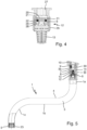
- the Fig. 1 to 5 The sanitary outlet fitting shown only with its relevant components for two different outlet pipe designs has an outlet pipe 1 which, in the design of the Fig. 1 to 4 a U-shaped pipe bend section 2 and in the design of Fig.5 bent twice at approximately 90° each.
- the pipe bend section 2 is concavely curved, ie it extends in the fluid flow direction initially with an upward and then downward directional component, each in combination with a horizontal extension component.
- the outlet fitting has a fluid channel 3 in the outlet pipe 1, which extends from a fluid inlet 30 in the outlet pipe 1 to a fluid outlet 5 from the outlet pipe 1.
- the fluid channel 3, ie the fluid-carrying channel of the outlet fitting in the outlet pipe 1 is separated from the entire interior of a pipe body 4 formed, the outside of which simultaneously forms the outside of the outlet pipe 1, ie the outlet pipe 1 in this case has no further, e.g. coaxially arranged pipe or hose body for fluid guidance.
- the fluid channel 3 is formed by a fluid-conducting, inner hose/pipe body running inside the outer pipe body 4.
- the fluid channel 3 runs in the design variant of the Fig. 1 to 4 in the area of the pipe bend section 2, as this is concavely curved, forming an upper reversal point Pu in the position of use.
- the reversal point Pu is, by definition, located at the highest point of the inner, lower curvature line of the curved, ie bent, section of the fluid channel 3, as in Fig.1 , ie the reversal point Pu is the highest point of the inner, lower curvature line of the pipe bend section 2 of the pipe body 4 forming the fluid channel 3 or the highest point of the inner, lower curvature line of the inner hose/pipe body.
- the altitude of the upper turning point Pu defines a Fig.1 height level H N shown in dashed lines, above which an air bubble or an air cushion can potentially form in a corresponding upper region 3a of the fluid channel 3 during operation of the fitting, if the amount of fluid flowing through the fluid channel 3 is not so large that the fluid fills the entire cross-section of the fluid channel 3, including in its upper region 3a.
- the height level H N represents the height up to which fluid can remain in the region upstream of the upper reversal point Pu in the fluid channel 3 when the fluid supply to the outlet pipe 1 or to the fluid channel 3 is shut off.
- the sanitary outlet fitting includes a quantity control element 6 arranged in an insert section 3b of the fluid channel 3, which automatically regulates the amount of fluid that can be released at the fluid outlet 5 of the fluid channel 3.
- the insert section 3b and thus the flow control element 6 is located in the area of the fluid inlet 30 into the outlet pipe 1 or downstream of it at another location in the fluid channel 3 upstream of the upper reversal point P u .
- the Fig.5 it is located in the area of the fluid inlet 30 into the outlet pipe 1 and thus in the inlet-side pipe section 1a of the outlet pipe 1.
- the flow control element 6 Without interaction by a user, the amount of fluid flowing out of the fluid outlet 5 of the fluid channel 3 can be kept constant even if fluid pressure fluctuations occur in the fluid supply.
- the insert section 3b of the fluid channel 3 is located in a straight pipe inlet section 7 of the outlet pipe 1.
- the insert section 3b, in which the flow control element 6 is arranged or inserted is located at another location upstream of the upper reversal point Pu, e.g. in an inlet-side region of the curved pipe bend section 2 or fluid channel section.
- the outlet pipe 1 has a fastening sleeve 8 on the inlet side, which has a fastening means 9 for fastening to a pipe support part 10 and an insert holder 11 in which an insert body 12, e.g. cylindrical, containing the flow control element 6 is accommodated.
- the insert body 12 is releasably screwed into a corresponding internal thread of the insert holder 11 with an external thread 26.
- the insert body 12 has a tool attachment contour 27, e.g. an internal hexagon contour, to which a corresponding tool can be attached as a screwing aid.
- the fastening means 9 can be, for example, a screw connection, as shown, or alternatively another conventional fastening means for preferably detachably securing the fastening sleeve 8 to the pipe support part 10.
- the pipe support part 10 is, for example, an associated pipe connection area of the outlet fitting or a fitting housing body, or alternatively a part of a base supporting the outlet pipe 1, on or on which the outlet fitting is located, such as a washbasin or bathtub or kitchen sink surface.
- the outlet fitting has a particle sieve 13, as in the example shown, which is arranged in the insert body 12 upstream of the flow control element 6. This keeps dirt and lime particles etc. away from the flow control element 6.
- the outlet pipe 1 comprises, as in the example shown, the pipe body 4 and a reinforcing sleeve 14 which is rigidly connected to the pipe body 4 on the inlet side on its inside, via which the pipe body 4 is held pivotably on the fastening sleeve 8, wherein the reinforcing sleeve 14 coaxially surrounds the fastening sleeve 8.
- the reinforcing sleeve 14 can be connected to the pipe body 4 in a non-detachable or alternatively detachable manner.
- the outlet pipe 1 is held pivotably on the fastening sleeve 8 by other conventional pivot bearing means.
- the reinforcing sleeve 14 is optional and can be omitted in corresponding embodiments.
- a pivot bearing is used to pivotally mount the tubular body 4 on the fastening sleeve 8, which comprises an annular recess 15 on the outer circumference of the fastening sleeve 8 and an arcuate pivot guide element 16 which is rotatably arranged in this recess 15 and to which the tubular body 4 together with the reinforcing sleeve 14 is connected by means of a screw 17.
- the pivot guide element 16 can move into and out of the reinforcing sleeve 14 via an annular recess 24 in a front end region of the reinforcing sleeve 14.
- the tubular body 4 together with the reinforcing sleeve 14 can be pulled axially off the fastening sleeve 8 after loosening the screw 17, after which the fastening sleeve 8 can be detached from the pipe support part 10.
- the outlet fitting has, as in the example shown, the Fig. 1 to 4 , optionally also in the example of Fig.5 , a swivel limiting sleeve 18 connected to the fastening sleeve 8 in a rotationally fixed manner and a stop cam 19 on the reinforcing sleeve 14 projecting radially inwards.
- the rotationally fixed connection can be realized in any suitable conventional manner, e.g. as in the example shown by the interaction of an inner gear ring 25 on the fastening sleeve 8 with a corresponding outer gear ring on the swivel limiting sleeve 18.
- the stop cam 19 interacts with the swivel limiting sleeve 18 to limit the swivel angle for the swivel movement of the outlet pipe 1, for which purpose the swivel limiting sleeve 18 has a corresponding, circular arc-shaped counter stop cam 18a in the example shown.
- the swivel limiting sleeve 18 has a corresponding, circular arc-shaped counter stop cam 18a in the example shown.
- the flow control element 6 comprises, as in the example shown, a perforated disc area 20 with one or more passage openings 21, of which in the sectional view of Fig.4 one can be seen and another is indicated by dashed lines, and a regulating body 22 which deforms depending on an existing fluid pressure and which adjusts a passage cross-section of the at least one passage opening 21 as a function of the fluid pressure, reducing it with increasing fluid pressure.
- the regulating body 22 is formed by a rubber-elastic O-ring which is located in an annular receptacle 28 of a cylindrical insert component 29 which has the perforated disk region 20 at its downstream end.
- the O-ring pressed against the disk region 20 deforms in the sense of greater flattening and thereby covers an additional part of the free passage cross-section of the respective passage opening 21.
- This reduction in the passage cross-section counteracts the increased fluid pressure in the sense of keeping the amount of fluid allowed through by the quantity control element 6 constant.
- the flattening of the O-ring decreases with decreasing fluid pressure, so that the O-ring exposes a larger passage cross-section of the respective passage opening 21, whereby in turn the amount of fluid passing through the flow control element 6 is kept constant despite decreasing fluid pressure.
- the outlet fitting has an aerator and/or jet regulator element 23 arranged at the fluid outlet 5 of the fluid channel 3, as in the example shown.
- This allows the characteristics of the fluid or water jet emerging from the fluid outlet 5 to be influenced in the desired manner.
- the quantity regulator element 6 and the aerator and/or jet regulator element 23 are suitably coordinated with one another in such a way that the aerator and/or jet regulator element 23, or alternatively another fluid flow-influencing element at the fluid outlet 5, does not prevent the fluid quantity regulated by the quantity regulator element 6 from emerging at the fluid outlet 5, i.e. the aerator and/or jet regulator element 23 or another fluid flow-influencing element arranged there does not generate any back pressure in the fluid channel 3.
- the invention provides an advantageous sanitary outlet fitting in which an undesirably long run-on of residual fluid after the fluid supply has been shut off due to a back pressure in the outlet pipe caused by an outlet-side fluid flow-influencing element or due to volume expansion of a compressed air bubble in the fluid channel of the outlet pipe can be avoided.
- the flow control element is arranged in the fluid channel in the inlet area of the outlet pipe and/or upstream of the upper turning point of the concavely curved pipe bend section or the corresponding curved fluid channel section, which is designed to automatically regulate the amount of fluid that can be released at the fluid outlet of the fluid channel.
- This determination can be made in particular in such a way that no fluid pressure builds up downstream of the flow control element and thus also in the bend area of a fluid channel that is concavely curved upwards, which could compress an air bubble located in the upper bend area of the fluid channel.
Landscapes
- Engineering & Computer Science (AREA)
- Health & Medical Sciences (AREA)
- Life Sciences & Earth Sciences (AREA)
- Hydrology & Water Resources (AREA)
- Public Health (AREA)
- Water Supply & Treatment (AREA)
- Chemical & Material Sciences (AREA)
- Chemical Kinetics & Catalysis (AREA)
- General Engineering & Computer Science (AREA)
- Mechanical Engineering (AREA)
- Pipe Accessories (AREA)
Description
- Die Erfindung bezieht sich auf eine sanitäre Auslaufarmatur mit einem Auslaufrohr und einem Fluidkanal im Auslaufrohr, der sich von einem Fluideintritt in das Auslaufrohr zu einem Fluidaustritt aus dem Auslaufrohr erstreckt.
- Der Fluidkanal kann je nach Ausführung der Auslaufarmatur beispielsweise vom gesamten Innenraum eines mit seiner Außenseite eine Außenseite des Auslaufrohrs bildenden Rohrkörpers oder vom Innenraum eines durch einen solchen äußeren Rohrkörper hindurchgeführten, fluidführenden Schlauchs oder inneren Rohrs gebildet sein. Der Fluidkanal endet in Fluidströmungsrichtung mit einem Fluidaustritt, an dem ein in der Auslaufarmatur geführtes und von ihr bereitzustellendes Fluid, typischerweise Wasser, zur Benutzung durch einen Nutzer aus der Auslaufarmatur austritt.
- Oftmals ist bei diesen Auslaufarmaturen am Fluidaustritt ein Partikelsieb, ein Luftsprudlerelement, ein Strahlreglerelement und/oder ein anderes, die Fluidströmung selbsttätig beeinflussendes Element angeordnet. In diesem Fall kann der Effekt auftreten, dass nach Abstellen der Fluidzufuhr noch unerwünscht lange Fluid aus dem Fluidaustritt nachtropft, wenn sich im Auslaufrohr durch das am Fluidaustritt angeordnete Element ein Staudruck aufgebaut hat.
- Bei einer bestimmten Art dieser Auslaufarmaturen besitzt das Auslaufrohr einen U-förmigen Rohrbogenabschnitt, der in Gebrauchslage mit konkaver Krümmung in Fluidströmungsrichtung zunächst mit nach oben und anschließend mit nach unten weisender Richtungskomponente verläuft. Mit Gebrauchslage ist hierbei wie üblich diejenige Lage gemeint, die das Auslaufrohr einnimmt, wenn sich die sanitäre Auslaufarmatur und damit auch deren Auslaufrohr in Gebrauch befindet, z.B. nach Montage an einem gewünschten Gebrauchsort. Entsprechend diesem Verlauf des Rohrbogenabschnitts verläuft auch der Fluidkanal im Auslaufrohr in Gebrauchslage im Bereich des Rohrbogenabschnitts in Fluidströmungsrichtung konkav gekrümmt, d.h. unter Bildung eines oberen Umkehrpunktes zunächst mit nach oben und anschließend mit nach unten weisender Richtungskomponente, wobei der Fluidkanal am oberen Umkehrpunkt von seiner Erstreckung mit nach oben weisender Richtungskomponente in seine anschließende Erstreckung mit nach unten weisender Richtungskomponente wechselt. Derartige Auslaufarmaturen werden beispielsweise als Wasserausläufe von Mischerarmaturen und Absperrarmaturen an Waschtischen, Badewannen und Küchenspülen verwendet. Auslaufarmaturen dieser Art mit durch einen äußeren Rohrkörper hindurchgeführtem Schlauch bzw. Innenrohr sind in den Offenlegungsschriften
DE 10 2012 212 303 A1 undUS 2010/0213398 A1 offenbart. Eine Auslaufarmatur dieses Typs, bei dem ein äußerer Rohrkörper gleichzeitig den Fluidkanal bildet, ist in den OffenlegungsschriftenUS 2007/0295418 A1 undDE 10 2007 040 495 A1 offenbart. - Bei einer in der Offenlegungsschrift
US 2003/0093857 A1 offenbarten sanitären Auslaufarmatur ist ein U-förmig konkav gekrümmtes Auslaufrohr eintrittsseitig mit einem Außenflansch versehen und mit einem axial vorstehenden Rohrendabschnitt in einen breiteren Abschnitt einer gestuft hülsenförmigen Rohraufnahme eingefügt und an letzterer durch Fixieren des Außenflanschs an einem korrespondierenden stirnseitigen Flansch der Rohraufnahme gehalten. An einem schmaleren Abschnitt der Rohraufnahme ist an einem gegenüberliegenden Stirnende ein Anschlussrohr gehalten. Im Übergang der beiden Abschnitte der Rohraufnahme ist innenseitig ein ringförmiger Sitz gebildet, auf dem ein strömungsregulierendes Element angeordnet und durch einen Schnappring gehalten ist, das dafür eingerichtet ist, eine laminare gleichmäßige Strömung im Auslaufrohr bereitzustellen. - Weitere herkömmliche sanitäre Auslaufarmaturen, in denen ein strömungsregulierendes Element insbesondere in Form eines Mengenreglerelements angeordnet ist, sind in der Gebrauchsmusterschrift
DE 84 35 378 U1 und den OffenlegungsschriftenWO 2009/067083 A1 ,JP H05-100749 A EP 0 469 391 A1 offenbart. - Bei heutigen Auslaufarmaturen besteht zunehmend der Wunsch, die Fluiddurchflussmenge möglichst gering zu halten, um beispielsweise Wasser zu sparen. Dadurch kann bei den Auslaufarmaturen mit konkav gekrümmtem Auslaufrohr speziell der Effekt auftreten, dass im Bereich des konkav gekrümmten Rohrbogenabschnitts des Fluidkanals eine Luftblase bzw. ein Luftpolster oberhalb des Niveaus des oberen Umkehrpunkts verbleibt und wegen der relativ niedrigen Durchflussrate nicht durch den Fluidfluss ausgespült wird. Dies kann, wenn sich am Fluidaustritt ein durchflussregelndes oder durchflussbegrenzendes oder durchflusshemmendes Element, wie z.B. ein Strahlformer, befindet, dazu führen, dass sich im aktiven Gebrauch der Armatur ein Innendruck im Fluidkanal aufbaut, der die im konkav gekrümmten Bogenbereich des Fluidkanals vorhandene Luftblase komprimiert. Bei einer anschließenden Absperrung der Fluidzufuhr an einer stromaufwärts des oberen Umkehrpunkts bzw. des Luftpolsters liegenden Absperrstelle, z.B. durch ein dort noch innerhalb der Armatur oder dieser vorgelagert angeordnetes, nutzerbetätigtes Absperrventil, baut sich der Fluiddruck im Fluidkanal ab, wodurch sich das komprimierte Luftpolster im Bogenbereich des Fluidkanals wieder ausdehnt. Diese Luftpolsterausdehnung kann dazu führen, dass unerwünscht lange Restfluid nachläuft, d.h. noch aus dem Fluidaustritt herausläuft bzw. nachtropft. Ein ähnliches unerwünschtes Nachtropfen kann aufgrund eines Staudrucks stromaufwärts eines am Fluidaustritt angeordneten, strömungsbeeinflussenden Elements auch bei den gattungsgemäßen Auslaufarmaturen auftreten, bei denen das Auslaufrohr keinen U-förmig nach oben gebogenen Rohrabschnitt aufweist.
- Der Erfindung liegt als technisches Problem die Bereitstellung einer sanitären Auslaufarmatur der eingangs genannten Art zugrunde, mit der sich das erwähnte, längere Nachlaufen bzw. Nachtropfen von Restfluid aus dem Fluidaustritt des Fluidkanals nach Absperrung der Fluidzufuhr vermeiden lässt.
- Die Erfindung löst dieses Problem durch die Bereitstellung einer sanitären Auslaufarmatur mit den Merkmalen des Anspruchs 1.
- Diese Auslaufarmatur beinhaltet ein Mengenreglerelement, das in einem hierfür vorgesehenen Einsatzabschnitt des Fluidkanals angeordnet ist und das die am Fluidaustritt des Fluidkanals abgebbare Fluidmenge selbsttätig regelnd festlegt. Der Einsatzabschnitt und damit das dort eingesetzte Mengenreglerelement befindet sich charakteristischerweise im Bereich des Fluideintritts und/oder, wenn das Auslaufrohr einen U-förmigen, in Gebrauchslage konkav gekrümmten Rohrbogenabschnitt aufweist und der Fluidkanal im Bereich des Rohrbogenabschnitts unter Bildung eines in Gebrauchslage oberen Umkehrpunktes verläuft, stromaufwärts des oberen Umkehrpunktes.
- Unter der selbsttätig regelnden Festlegung der am Fluidaustritt abgebbaren Fluidmenge durch das Mengenreglerelement ist zu verstehen, dass das Mengenreglerelement diejenige Komponente der Auslaufarmatur ist, welche die am Fluidaustritt von der Armatur abgegebene Fluidmenge bestimmt, wobei das Mengenreglerelement diese Fluidmenge selbsttätig regelt. Derartige Mengenreglerelemente sind dem Fachmann an sich bekannt, was daher hier keiner näheren Erläuterungen bedarf. Beispielsweise sind derartige Mengenreglerelemente in Ausführungen geläufig, bei denen ein gummielastischer Ring abhängig vom anstehenden Fluiddruck eine oder mehrere Durchlassöffnungen für das in der Armatur geführte Fluid mehr oder weniger absperrt, d.h. den für das Fluid effektiv zur Verfügung stehenden Durchflussquerschnitt abhängig vom anstehenden Fluiddruck variabel einstellt, insbesondere einen mit ansteigendem Fluiddruck geringer werdenden Durchflussquerschnitt. Mit anderen Worten hält das Mengenreglerelement die Fluiddurchflussmenge selbsttätig auch bei Druckschwankungen des zugeführten Fluids im Wesentlichen konstant.
- Da das Mengenreglerelement dafür eingerichtet bzw. daraufhin ausgelegt ist, dass es diejenige Komponente der Armatur ist, welche die am Fluidaustritt des Fluidkanals und damit der Armatur im aktiven Betrieb abgegebene Fluidmenge bestimmt, kann sich im aktiven Betrieb kein Staudruck des Fluids stromabwärts des Mengenreglerelements aufbauen, denn das Mengenreglerelement lässt gemäß dieser Auslegung jeweils nur diejenige Fluidmenge passieren, die am Fluidaustritt auch ohne erneuten Druckaufbau abgegeben werden kann, so dass sich das Fluid im Bereich zwischen dem Mengenreglerelement und dem Fluidaustritt nicht stauen kann. Als Folge hiervon braucht nach Abstellen der Fluidzufuhr kein Staudruck abgebaut werden, und kann es auch nicht zu einem Kompressionseffekt für eine Luftblase kommen, die sich eventuell oberhalb des Niveaus des oberen Umkehrpunkts in einem konkav gekrümmten Bereich des Fluidkanals gebildet hat, da sich dieser Bereich stromabwärts des Mengenreglerelements befindet.
- Demgemäß vermeidet die erfindungsgemäße Auslaufarmatur ein längeres Nachtropfen bzw. Nachlaufen von Restfluid nach Absperren der Fluidzufuhr aufgrund Volumenausdehnung eines zuvor komprimierten Luftpolsters im konkav gekrümmten Fluidkanalabschnitt oder aufgrund eines anderweitig verursachten Staudrucks von Fluid im Auslaufrohr. Es versteht sich, dass stromabwärts des Mengenreglerelements und insbesondere am Fluidaustritt bei Bedarf optional strömungsbeeinflussende Elemente herkömmlicher Art angeordnet sein können, z.B. ein Partikelsieb, ein Luftsprudlerelement und/oder ein Strahlregler, solange diese Elemente die am Fluidaustritt abgebbare Fluidmenge nicht weitergehend einschränken als durch das stromaufwärtige Mengenreglerelement vorgegeben.
- Weiter beinhaltet das Auslaufrohr eintrittsseitig eine Befestigungshülse, die ein Befestigungsmittel zur Befestigung an einem Rohrtragteil sowie eine Einsatzaufnahme aufweist, in welcher ein Einsatzkörper aufgenommen ist, der das Mengenreglerelement enthält. Dabei ist die Befestigungshülse im Inneren des Auslaufrohres aufgenommen und das Auslaufrohr durch ein Schwenklagerungsmittel schwenkbeweglich an der Befestigungshülse gehalten. Dies bietet unter anderem den Vorteil einer Doppelfunktionalität der Befestigungshülse einerseits zum Befestigen des Auslaufrohrs an einem Rohrtragteil und andererseits zum Aufnehmen des das Mengenreglerelement enthaltenden Einsatzkörpers. Bei dem Rohrtragteil kann es sich beispielsweise um eine angrenzende Befestigungsfläche der Auslaufarmatur selbst handeln, z.B. zum Anbringen des Auslaufrohrs an einem zugeordneten Rohranschlussbereich eines Gehäuses der Armatur, oder um einen zugeordneten Bereich einer nicht zur Armatur gehörigen Unterlage, wie einer Waschtischfläche, einer Badewannenfläche oder einer Küchenspülenfläche, an dem das Auslaufrohr in diesem Fall angebracht wird.
- In einer Weiterbildung der Erfindung befindet sich der Einsatzabschnitt des Fluidkanals, in dem das Mengenreglerelement angeordnet, insbesondere eingesetzt, ist, in einem geradlinig verlaufenden Rohreintrittsabschnitt des Auslaufrohrs. Der geradlinige Verlauf dieses eintrittsseitigen Abschnitts des Auslaufrohrs bietet in Kombination mit der Maßnahme, dort den Einsatzabschnitt des Fluidkanals zum Anordnen des Mengenreglerelements vorzusehen, für viele Anwendungen konstruktive und funktionelle Vorteile.
- In einer Weiterbildung der Erfindung beinhaltet die Auslaufarmatur ein Partikelsieb, das im Einsatzkörper stromaufwärts des Mengenreglerelements angeordnet ist. Das Partikelsieb kann auf diese Weise störende Schmutz- oder Kalkpartikel und dergleichen vom Mengenreglerelement fernhalten, und der zum Anordnen des Mengenreglerelements dienende Einsatzkörper nimmt zusätzlich das Partikelsieb auf, so dass zum Anordnen des Partikelsiebs kein zusätzliches Bauteil benötigt wird.
- In einer Weiterbildung der Erfindung umfasst das Auslaufrohr einen Rohrkörper und eine mit dem Rohrkörper eintrittsseitig an dessen Innenseite starr verbundene Verstärkungshülse, über die der Rohrkörper schwenkbeweglich an der Befestigungshülse gehalten ist, wobei die Verstärkungshülse die Befestigungshülse koaxial umgibt. Dies stellt eine konstruktiv vorteilhafte Ausführung für die Auslaufarmatur dar, da das Auslaufrohr im Gebrauch verschwenkbar ist.
- In einer Weiterbildung beinhaltet die Armatur eine drehfest mit der Befestigungshülse verbundene Schwenkbegrenzungshülse und einen an der Verstärkungshülse radial nach innen vorstehenden Anschlagnocken, der mit der Schwenkbegrenzungshülse zur Schwenkwinkelbegrenzung für die Schwenkbewegung des Auslaufrohrs zusammenwirkt. Dies stellt eine konstruktiv vorteilhafte Realisierung für eine in bestimmten Anwendungsfällen gewünschte, anschlagdefinierte Begrenzung des für das Verschwenken des Auslaufrohrs maximal möglichen Schwenkwinkels dar.
- In einer Weiterbildung der Erfindung umfasst das Mengenreglerelement einen perforierten Scheibenbereich mit mindestens einer Durchlassöffnung und einen sich abhängig von einem anstehenden Fluiddruck verformenden Regulierkörper, der einen Durchlassquerschnitt der mindestens einen Durchlassöffnung fluiddruckabhängig mit zunehmendem Fluiddruck verringernd einstellt. Dies stellt eine für den vorliegenden Anwendungsfall konstruktiv und funktionell vorteilhafte, mit relativ geringem Aufwand realisierbare Ausführung des Mengenreglerelements dar.
- In einer Weiterbildung der Erfindung beinhaltet die Auslaufarmatur ein am Fluidaustritt des Fluidkanals angeordnetes Luftsprudler- und/oder Strahlreglerelement. Das Luftsprudler- und/oder Strahlreglerelement kann von irgendeinem geeigneten herkömmlichen Aufbau sein und dient in an sich bekannter Weise zur Luftbeimischung und/oder Strahlregelung für einen am Fluidaustritt aus der Armatur austretenden Fluidstrahl.
- Vorteilhafte Ausführungsformen der Erfindung sind in den Zeichnungen dargestellt und werden nachfolgend beschrieben. Hierbei zeigen:
- Fig. 1
- eine Längsschnittansicht einer sanitären Auslaufarmatur mit ihren vorliegend interessierenden Komponenten,
- Fig. 2
- eine Detailansicht eines Bereichs II in
Fig. 1 bzw. 5, - Fig. 3
- eine Längsschnittansicht einer Befestigungshülse mit Befestigungsmittel und einer Einsatzaufnahme mit darin aufgenommenem, ein Mengenreglerelement enthaltendem Einsatzkörper,
- Fig. 4
- eine Längsschnittansicht des in
Fig. 3 verwendeten Einsatzkörpers mit dem Mengenreglerelement und mit einem Partikelsieb und - Fig. 5
- eine Längsschnittansicht entsprechend
Fig. 1 für eine Variante der Auslaufarmatur. - Die in den
Fig. 1 bis 5 nur mit ihren vorliegend relevanten Komponenten für zwei verschiedene Auslaufrohrgestaltungen gezeigte, sanitäre Auslaufarmatur weist ein Auslaufrohr 1 auf, das in der Ausführung derFig. 1 bis 4 einen U-förmigen Rohrbogenabschnitt 2 beinhaltet und in der Ausführung vonFig. 5 zweifach um je ca. 90° gebogen verläuft. - In der in
Fig. 1 gezeigten Gebrauchslage der Auslaufarmatur derFig. 1 bis 4 und damit auch in Gebrauchslage des Auslaufrohrs 1 und des Rohrbogenabschnitts 2 ist der Rohrbogenabschnitt 2 konkav gekrümmt, d.h. er erstreckt sich in Fluidströmungsrichtung zunächst mit nach oben weisender und anschließend mit nach unten weisender Richtungskomponente, jeweils in Kombination mit einer horizontalen Erstreckungskomponente. Auch inFig. 5 ist die dortige Ausführungsvariante in Gebrauchslage des Auslaufrohrs 1 gezeigt, wobei in diesem Fall das Auslaufrohr 1 in Gebrauchslage und in Fluidströmungsrichtung gesehen einen im Wesentlichen vertikal nach unten verlaufenden eintrittsseitigen Rohrabschnitt 1a, einen im Wesentlichen horizontal verlaufenden mittleren Rohrabschnitt 1b und einen im Wesentlichen vertikal nach unten verlaufenden austrittsseitigen Rohrabschnitt 1c aufweist. - Des Weiteren weist die Auslaufarmatur einen Fluidkanal 3 im Auslaufrohr 1 auf, der sich von einem Fluideintritt 30 in das Auslaufrohr 1 zu einem Fluidaustritt 5 aus dem Auslaufrohr 1 erstreckt. Im gezeigten Beispiel ist der Fluidkanal 3, d.h. der fluidführende Kanal der Auslaufarmatur im Auslaufrohr 1, vom gesamten Innenraum eines Rohrkörpers 4 gebildet, dessen Außenseite gleichzeitig die Außenseite des Auslaufrohrs 1 bildet, d.h. das Auslaufrohr 1 besitzt in diesem Fall keinen weiteren, z.B. koaxial angeordneten Rohr- oder Schlauchkörper zur Fluidführung. In alternativen Ausführungen ist der Fluidkanal 3 von einem im Inneren des äußeren Rohrkörpers 4 verlaufenden, fluidführenden, inneren Schlauch-/Rohrkörper gebildet.
- Der Fluidkanal 3 verläuft bei der Ausführungsvariante der
Fig. 1 bis 4 im Bereich des Rohrbogenabschnitts 2 wie dieser konkav gekrümmt unter Bildung eines in Gebrauchslage oberen Umkehrpunkts Pu Der Umkehrpunkt Pu befindet sich definitionsgemäß am höchsten Punkt der inneren, unteren Krümmungslinie des gekrümmt, d.h. gebogen, verlaufenden Abschnitts des Fluidkanals 3, wie inFig. 1 dargestellt, d.h. der Umkehrpunkt Pu ist der höchste Punkt der inneren, unteren Krümmungslinie des Rohrbogenabschnitts 2 des den Fluidkanal 3 bildenden Rohrkörpers 4 bzw. der höchste Punkt der inneren, unteren Krümmungslinie des inneren Schlauch-/Rohrkörpers. - Die Höhenlage des oberen Umkehrpunkts Pu definiert ein in
Fig. 1 gestrichelt wiedergegebenes Höhenniveau HN, über dem sich im Betrieb der Armatur potenziell in einem entsprechenden oberen Bereich 3a des Fluidkanals 3 eine Luftblase bzw. ein Luftpolster bilden kann, wenn die Menge an durch den Fluidkanal 3 hindurchfließendem Fluid nicht so groß ist, dass das Fluid den ganzen Querschnitt des Fluidkanals 3 auch in dessen oberem Bereich 3a ausfüllt. Das Höhenniveau HN stellt diejenige Höhe dar, bis zu der Fluid im Bereich stromaufwärts des oberen Umkehrpunkts Pu im Fluidkanal 3 stehen bleiben kann, wenn die Fluidzufuhr zum Auslaufrohr 1 bzw. zum Fluidkanal 3 abgestellt wird. Derjenige Fluidanteil, der beim Absperren der Fluidzufuhr zunächst über dem Höhenniveau HN oder in einem stromabwärtigen Abschnitt des Fluidkanals 3 bis zum Fluidaustritt 5 des Fluidkanals 3 vorliegt, strömt noch aus dem Fluidaustritt 5 aus. Des Weiteren beinhaltet die sanitäre Auslaufarmatur ein in einem Einsatzabschnitt 3b des Fluidkanals 3 angeordnetes Mengenreglerelement 6, das die am Fluidaustritt 5 des Fluidkanals 3 abgebbare Fluidmenge selbsttätig regelnd festlegt. Im Beispiel derFig. 1 bis 4 befindet sich der Einsatzabschnitt 3b und damit das Mengenreglerelement 6 im Bereich des Fluideintritts 30 in das Auslaufrohr 1 oder stromabwärts davon an anderer Stelle im Fluidkanal 3 stromaufwärts des oberen Umkehrpunkts Pu. Im Beispiel derFig. 5 befindet er sich im Bereich des Fluideintritts 30 in das Auslaufrohr 1 und damit im eintrittsseitigen Rohrabschnitt 1a des Auslaufrohrs 1. Durch das Mengenreglerelement 6 lässt sich ohne Interaktion durch einen Benutzer die am Fluidaustritt 5 des Fluidkanals 3 ausströmende Fluidmenge auch dann konstant halten, wenn in der Fluidzufuhr Fluiddruckschwankungen auftreten. - In entsprechenden Ausführungen befindet sich wie im gezeigten Beispiel der Einsatzabschnitt 3b des Fluidkanals 3 in einem geradlinig verlaufenden Rohreintrittsabschnitt 7 des Auslaufrohrs 1. In alternativen Ausführungen des Typs mit konkav gekrümmtem Auslaufrohr befindet sich der Einsatzabschnitt 3b, in welchem das Mengenreglerelement 6 angeordnet bzw. eingesetzt ist, an anderer Stelle stromaufwärts des oberen Umkehrpunkts Pu, z.B. in einem eintrittsseitigen Bereich des gekrümmten Rohrbogenabschnitts 2 bzw. Fluidkanalabschnitts.
- Weiter weist das Auslaufrohr 1 eintrittsseitig eine Befestigungshülse 8 auf, die ein Befestigungsmittel 9 zur Befestigung an einem Rohrtragteil 10 und eine Einsatzaufnahme 11 aufweist, in der ein das Mengenreglerelement 6 enthaltender, z.B. zylinderförmiger Einsatzkörper 12 aufgenommen ist. Im gezeigten Beispiel ist der Einsatzkörper 12 mit einem Außengewinde 26 lösbar in ein korrespondierendes Innengewinde der Einsatzaufnahme 11 eingeschraubt. Optional weist der Einsatzkörper 12 eine Werkzeugansatzkontur 27, z.B. eine Innensechskantkontur, auf, an der ein entsprechendes Werkzeug als Schraubhilfe angesetzt werden kann.
- Das Befestigungsmittel 9 kann beispielsweise eine Schraubverbindung, wie gezeigt, alternativ ein anderes herkömmliches Befestigungsmittel zur vorzugsweise lösbaren Festlegung der Befestigungshülse 8 am Rohrtragteil 10 sein. Das Rohrtragteil 10 ist beispielsweise ein zugehöriger Rohranschlussbereich der Auslaufarmatur bzw. eines Armaturengehäusekörpers, alternativ ein das Auslaufrohr 1 tragender Teil einer Unterlage, an oder auf der sich die Auslaufarmatur befindet, wie eine Waschtisch- oder Badewannen- oder Küchenspülenfläche.
- In entsprechenden Ausführungen besitzt die Auslaufarmatur wie im gezeigten Beispiel ein Partikelsieb 13, das im Einsatzkörper 12 stromaufwärts des Mengenreglerelements 6 angeordnet ist. Damit lassen sich Schmutz- und Kalkpartikel etc. vom Mengenreglerelement 6 fernhalten.
- In vorteilhaften Realisierungen umfasst das Auslaufrohr 1 wie beim gezeigten Beispiel den Rohrkörper 4 und eine mit dem Rohrkörper 4 eintrittsseitig an dessen Innenseite starr verbundene Verstärkungshülse 14, über die der Rohrkörper 4 schwenkbeweglich an der Befestigungshülse 8 gehalten ist, wobei die Verstärkungshülse 14 die Befestigungshülse 8 koaxial umgibt. Die Verstärkungshülse 14 kann unlösbar oder alternativ lösbar mit dem Rohrkörper 4 verbunden sein. In alternativen, nicht gezeigten Ausführungen ist das Auslaufrohr 1 durch andere herkömmliche Schwenklagerungsmittel schwenkbeweglich an der Befestigungshülse 8 gehalten. Die Verstärkungshülse 14 ist optional und kann in entsprechenden Ausführungen fehlen.
- Zur schwenkbeweglichen Halterung des Rohrkörpers 4 an der Befestigungshülse 8 dient im gezeigten Beispiel ein Schwenklager, das eine ringförmige Ausnehmung 15 am Außenumfang der Befestigungshülse 8 und ein in dieser Ausnehmung 15 drehbar angeordnetes, bogenförmiges Schwenkführungselement 16 umfasst, mit dem der Rohrkörper 4 samt Verstärkungshülse 14 mittels einer Schraube 17 verbunden ist. Das Schwenkführungselement 16 kann wie gezeigt über eine ringförmige Ausnehmung 24 in einem Stirnendbereich der Verstärkungshülse 14 in die Verstärkungshülse 14 hinein bzw. heraus gelangen. Dadurch kann zur Demontage der Armatur der Rohrkörper 4 samt Verstärkungshülse 14 nach Lösen der Schraube 17 von der Befestigungshülse 8 axial abgezogen werden, wonach die Befestigungshülse 8 vom Rohrtragteil 10 gelöst werden kann.
- In einer vorteilhaften Realisierung besitzt die Auslaufarmatur wie im gezeigten Beispiel der
Fig. 1 bis 4 , optional auch im Beispiel vonFig. 5 , eine drehfest mit der Befestigungshülse 8 verbundene Schwenkbegrenzungshülse 18 und einen an der Verstärkungshülse 14 radial nach innen vorstehenden Anschlagnocken 19. Die drehfeste Verbindung kann auf irgendeine geeignete herkömmliche Art realisiert sein, z.B. wie im gezeigten Beispiel durch Zusammenwirken eines inneren Zahnkranzes 25 an der Befestigungshülse 8 mit einem korrespondierenden äußeren Zahnkranz an der Schwenkbegrenzungshülse 18. Der Anschlagnocken 19 wirkt mit der Schwenkbegrenzungshülse 18 zur Schwenkwinkelbegrenzung für die Schwenkbewegung des Auslaufrohrs 1 zusammen, wozu im gezeigten Beispiel die Schwenkbegrenzungshülse 18 einen korrespondierenden, kreisbogenförmigen Gegenanschlagnocken 18a aufweist. Durch geeignete Wahl der Bogenlänge des Gegenanschlagnockens 18a und/oder des Anschlagnockens 19 lässt sich der maximal mögliche Schwenkwinkelbereich für das Auslaufrohr 1 in gewünschter Weise vorgeben. - In einer vorteilhaften Ausführung umfasst das Mengenreglerelement 6 wie im gezeigten Beispiel einen perforierten Scheibenbereich 20 mit einer oder mehreren Durchlassöffnungen 21, von denen in der Schnittansicht von
Fig. 4 eine zu erkennen ist und eine weitere gestrichelt angedeutet ist, und einen sich abhängig von einem anstehenden Fluiddruck verformenden Regulierkörper 22, der einen Durchlassquerschnitt der mindestens einen Durchlassöffnung 21 fluiddruckabhängig mit zunehmendem Fluiddruck verringernd einstellt. Im gezeigten Beispiel ist der Regulierkörper 22 von einem gummielastischen O-Ring gebildet, der sich in einer ringförmigen Aufnahme 28 eines zylindrischen Einsatzbauteils 29 befindet, das an seinem stromabwärtigen Stirnende den perforierten Scheibenbereich 20 aufweist. Wenn sich der vom anströmenden Fluid ausgeübte Fluiddruck erhöht, verformt sich der gegen den Scheibenbereich 20 angedrückte O-Ring im Sinn einer stärkeren Abplattung und deckt dadurch einen zusätzlichen Teil des freien Durchlassquerschnitts der jeweiligen Durchlassöffnung 21 ab. Diese Verringerung des Durchlassquerschnitts wirkt dem erhöhten Fluiddruck im Sinn einer Konstanthaltung der vom Mengenreglerelement 6 durchgelassenen Fluidmenge entgegen. Umgekehrt nimmt die Abplattung des O-Rings mit abnehmendem Fluiddruck ab, so dass der O-Ring einen größeren Durchlassquerschnitt der jeweiligen Durchlassöffnung 21 freigibt, wodurch wiederum trotz nachlassendem Fluiddruck die das Mengenreglerelement 6 passierende Fluidmenge konstant gehalten wird. - In entsprechenden Realisierungen weist die Auslaufarmatur ein am Fluidaustritt 5 des Fluidkanals 3 angeordnetes Luftsprudler- und/oder Strahlreglerelement 23 auf, wie im gezeigten Beispiel. Damit kann die Charakteristik des aus dem Fluidaustritt 5 austretenden Fluid- bzw. Wasserstrahls in gewünschter Weise beeinflusst werden. Dabei sind das Mengenreglerelement 6 und das Luftsprudler- und/oder Strahlreglerelement 23 geeignet derart aufeinander abgestimmt, dass das Luftsprudler- und/oder Strahlreglerelement 23, oder alternativ ein anderes fluidströmungsbeeinflussendes Element am Fluidaustritt 5, die vom Mengenreglerelement 6 eingeregelte Fluidmenge nicht am Austreten am Fluidaustritt 5 behindert, d.h. das Luftsprudler- und/oder Strahlreglerelement 23 oder ein anderes dort angeordnetes, fluidströmungsbeeinflussendes Element erzeugt keinen Staudruck im Fluidkanal 3.
- Insbesondere wird dadurch im Beispiel der
Fig. 1 bis 4 auch vermieden, dass ein sich eventuell im gebogenen Fluidkanalbereich 3a über dem Höhenniveau HN des oberen Umkehrpunkts Pu des Fluidkanals 3 befindliches Luftpolster durch einen solchen Staudruck im Fluidkanal 3 komprimiert wird, was dann wie oben erläutert zu dem unerwünschten längeren Nachlaufen bzw. Nachtropfen von Restfluid aus dem Fluidaustritt 5 heraus nach dem Abstellen der Fluidzufuhr führen könnte. - Wie die gezeigten und die weiteren oben erläuterten Ausführungsbeispiele deutlich machen, stellt die Erfindung eine vorteilhafte sanitäre Auslaufarmatur zur Verfügung, bei der ein unerwünscht langes Nachlaufen von Restfluid nach Abstellen der Fluidzufuhr aufgrund eines durch ein austrittsseitiges fluidströmungsbeeinflussendes Element verursachten Staudrucks im Auslaufrohr bzw. aufgrund Volumenausdehnung einer komprimierten Luftblase im Fluidkanal des Auslaufrohrs vermieden werden kann.
- Dazu ist im Fluidkanal das Mengenreglerelement im Eintrittsbereich des Auslaufrohrs und/oder stromaufwärts des oberen Umkehrpunkts des konkav gekrümmten Rohrbogenabschnitts bzw. des korrespondierenden gebogenen Fluidkanalabschnitts angeordnet, das dafür ausgelegt ist, die am Fluidaustritt des Fluidkanals abgebbare Fluidmenge selbsttätig regelnd festzulegen. Diese Festlegung lässt sich insbesondere so treffen, dass sich stromabwärts des Mengenreglerelements und damit auch im Bogenbereich eines konkav nach oben gekrümmt verlaufenden Fluidkanals kein Fluiddruck aufbaut, der eine im oberen Bogenbereich des Fluidkanals befindliche Luftblase komprimieren könnte.
Claims (7)
- Sanitäre Auslaufarmatur mit- einem Auslaufrohr (1),- einem Fluidkanal (3) im Auslaufrohr, der sich von einem Fluideintritt (30) in das Auslaufrohr (1) zu einem Fluidaustritt (5) aus dem Auslaufrohr (1) erstreckt,- einem in einem Einsatzabschnitt (3b) des Fluidkanals (3) angeordneten Mengenreglerelement (6), das die an dem Fluidaustritt (5) des Fluidkanals (3) abgebbare Fluidmenge selbsttätig regelnd festlegt,- wobei sich der Einsatzabschnitt (3b) im Bereich des Fluideintritts (30) befindet und/oder wobei das Auslaufrohr (1) einen U-förmigen, in Gebrauchslage konkav gekrümmten Rohrbogenabschnitt (2) aufweist, der Fluidkanal (3) im Bereich des Rohrbogenabschnitts (2) unter Bildung eines in Gebrauchslage oberen Umkehrpunktes (Pu) verläuft und sich der Einsatzabschnitt (3b) stromaufwärts des oberen Umkehrpunktes (Pu) befindet, und- einer Befestigungshülse (8) an einer Eintrittsseite des Auslaufrohrs (1), wobei die Befestigungshülse (8) im Inneren des Auslaufrohres (1) aufgenommen ist, das Auslaufrohr (1) durch ein Schwenklagerungsmittel schwenkbeweglich an der Befestigungshülse (8) gehalten ist und die Befestigungshülse (8) ein Befestigungsmittel (9) zur Befestigung an einem Rohrtragteil und eine Einsatzaufnahme (11) aufweist, in der ein das Mengenreglerelement (6) enthaltender Einsatzkörper (12) aufgenommen ist.
- Sanitäre Auslaufarmatur nach Anspruch 1, weiter dadurch gekennzeichnet, dass sich der Einsatzabschnitt (3b) des Fluidkanals (3) in einem geradlinig verlaufenden Rohreintrittsabschnitt (7) des Auslaufrohrs (1) befindet.
- Sanitäre Auslaufarmatur nach Anspruch 1 oder 2, weiter gekennzeichnet durch ein im Einsatzkörper (12) stromaufwärts des Mengenreglerelements (6) angeordnetes Partikelsieb (13).
- Sanitäre Auslaufarmatur nach einem der Ansprüche 1 bis 3, weiter dadurch gekennzeichnet, dass das Auslaufrohr (1) einen Rohrkörper (4) und eine mit dem Rohrkörper (4) eintrittsseitig an dessen Innenseite starr verbundene Verstärkungshülse (14) umfasst, über die der Rohrkörper (4) schwenkbeweglich an der Befestigungshülse (8) gehalten ist, wobei die Verstärkungshülse (14) die Befestigungshülse (8) koaxial umgibt.
- Sanitäre Auslaufarmatur nach einem der Ansprüche 1 bis 4, weiter gekennzeichnet durch eine drehfest mit der Befestigungshülse (8) verbundene Schwenkbegrenzungshülse (18) und einen an der Verstärkungshülse (14) radial nach innen vorstehenden Anschlagnocken (19), der mit der Schwenkbegrenzungshülse (18) zur Schwenkwinkelbegrenzung für die Schwenkbewegung des Auslaufrohrs (1) zusammenwirkt.
- Sanitäre Auslaufarmatur nach einem der Ansprüche 1 bis 5, weiter dadurch gekennzeichnet, dass das Mengenreglerelement (6) einen perforierten Scheibenbereich (20) mit mindestens einer Durchlassöffnung (21) und einen sich abhängig von einem anstehenden Fluiddruck verformenden Regulierkörper (22) umfasst, der einen Durchlassquerschnitt der mindestens einen Durchlassöffnung (21) fluiddruckabhängig mit zunehmendem Fluiddruck verringernd einstellt.
- Sanitäre Auslaufarmatur nach einem der Ansprüche 1 bis 6, weiter gekennzeichnet durch ein am Fluidaustritt des Fluidkanals (3) angeordnetes Luftsprudler- und/oder Strahlformerelement (23).
Applications Claiming Priority (1)
| Application Number | Priority Date | Filing Date | Title |
|---|---|---|---|
| DE102019210111.9A DE102019210111B4 (de) | 2019-07-09 | 2019-07-09 | Sanitäre Auslaufarmatur mit Auslaufrohr |
Publications (2)
| Publication Number | Publication Date |
|---|---|
| EP3763889A1 EP3763889A1 (de) | 2021-01-13 |
| EP3763889B1 true EP3763889B1 (de) | 2024-05-22 |
Family
ID=71522999
Family Applications (1)
| Application Number | Title | Priority Date | Filing Date |
|---|---|---|---|
| EP20184366.1A Active EP3763889B1 (de) | 2019-07-09 | 2020-07-07 | Sanitäre auslaufarmatur mit auslaufrohr |
Country Status (3)
| Country | Link |
|---|---|
| EP (1) | EP3763889B1 (de) |
| CN (1) | CN112212046B (de) |
| DE (1) | DE102019210111B4 (de) |
Family Cites Families (15)
| Publication number | Priority date | Publication date | Assignee | Title |
|---|---|---|---|---|
| DE8435378U1 (de) * | 1984-12-03 | 1985-03-28 | GVB SANIMED Hygiene- und Medizintechnik GmbH, 3070 Nienburg | Injektordosierkopf |
| DE4023988C2 (de) * | 1990-07-28 | 1997-02-13 | Ideal Standard | Sanitärarmatur |
| JP2517801B2 (ja) * | 1991-05-08 | 1996-07-24 | 株式会社ピコ・エイダ | 定量用バルブ |
| DE19527232A1 (de) * | 1995-07-26 | 1997-01-30 | Grohe Armaturen Friedrich | Auslaufarmatur |
| JP2002351549A (ja) * | 2001-05-25 | 2002-12-06 | Shodensha:Kk | 定流量器 |
| US7207075B2 (en) * | 2001-11-20 | 2007-04-24 | Speakman Company | Interchangeable gooseneck faucet |
| EP1870526B1 (de) * | 2006-06-21 | 2016-04-06 | Franke Water Systems AG | Sanitärarmatur |
| DE102007040495A1 (de) * | 2007-08-21 | 2009-02-26 | Hansgrohe Ag | Sanitärarmatur |
| WO2009067083A1 (en) * | 2007-11-21 | 2009-05-28 | Jvl Engineering Pte Ltd | Water flow regulating device |
| EP2224065B1 (de) * | 2009-02-25 | 2013-07-17 | Kwc Ag | Sanitärarmatur mit isoliertem Ausflussrohr |
| DE102012201230A1 (de) | 2012-01-27 | 2013-08-01 | Dufour Industries SA | Steigfellfixierungsvorrichtung |
| DE102012212303A1 (de) * | 2012-07-13 | 2014-01-16 | Hansgrohe Se | Sanitärarmatur |
| DE202013000860U1 (de) * | 2013-01-29 | 2014-05-05 | Neoperl Gmbh | Sanitäres Einbauteil und Komponente einer Sanitärarmatur |
| DE102013003925A1 (de) * | 2013-03-08 | 2014-09-11 | Neoperl Gmbh | Sanitäres Einbauteil, Einbauteil-Anordnung und Sanitärarmatur |
| DE102015219175B4 (de) * | 2015-10-05 | 2024-05-08 | Hansgrohe Se | Anschlussrohrstutzen für eine Sanitärarmatur |
-
2019
- 2019-07-09 DE DE102019210111.9A patent/DE102019210111B4/de active Active
-
2020
- 2020-07-07 EP EP20184366.1A patent/EP3763889B1/de active Active
- 2020-07-09 CN CN202010656826.9A patent/CN112212046B/zh active Active
Also Published As
| Publication number | Publication date |
|---|---|
| CN112212046B (zh) | 2022-08-30 |
| DE102019210111A1 (de) | 2021-01-14 |
| EP3763889A1 (de) | 2021-01-13 |
| DE102019210111B4 (de) | 2021-05-20 |
| CN112212046A (zh) | 2021-01-12 |
Similar Documents
| Publication | Publication Date | Title |
|---|---|---|
| EP2100201B1 (de) | Durchflussmengenregler | |
| EP2536886B1 (de) | Sanitäres einbauelement für wasserauslauf | |
| EP2100200B1 (de) | Durchflussmengenregler | |
| DE19603393A1 (de) | Durchflußmengenregler oder dergleichen Drossel | |
| EP1516237B1 (de) | Durchflussmengenregler | |
| DE69908635T2 (de) | Durchflussbegrenzer | |
| CH652782A5 (de) | Schwimmergesteuertes wasserzulaufventil. | |
| DE102005003404B3 (de) | Sanitäre Auslaufeinheit | |
| DE69720678T2 (de) | Wassersparendes ventil mit konstantem durchfluss und brausekopf ausgerüstet mit einem solchen ventil | |
| EP0469391B2 (de) | Sanitärarmatur | |
| EP2582890A1 (de) | Sanitäre einsetzeinheit sowie brausearmatur mit einer sanitären einsetzeinheit | |
| AT413401B (de) | Strahlregler mit belüftungseinrichtung | |
| EP2597213B1 (de) | Sanitäres Einbauteil | |
| DE69005267T2 (de) | Brauseeinheit. | |
| EP0444414B1 (de) | Sanitäre Armatur mit einer Sicherungseinrichtung zum verhindern des Zurückfliessens von Wasser | |
| DE10312854B4 (de) | Sanitäre Einsetzeinheit | |
| DE19806451A1 (de) | Durchflußmengenregler | |
| EP3318683A1 (de) | Fluidverteilerkörper und sanitärbrause | |
| DE102019210111B4 (de) | Sanitäre Auslaufarmatur mit Auslaufrohr | |
| EP2159337B1 (de) | Bodenablauf, insbesondere für bodengleiche Dusche | |
| EP1686218A1 (de) | Sanitärarmatur mit schwenkbarem Wasserauslass | |
| DE102015014309B4 (de) | Strahlregler | |
| EP2634317B1 (de) | Sanitärarmatur | |
| EP2233648A1 (de) | Trink- und Brauchwassersystem | |
| DE102006021801A1 (de) | Sanitäre Auslaufeinheit |
Legal Events
| Date | Code | Title | Description |
|---|---|---|---|
| PUAI | Public reference made under article 153(3) epc to a published international application that has entered the european phase |
Free format text: ORIGINAL CODE: 0009012 |
|
| STAA | Information on the status of an ep patent application or granted ep patent |
Free format text: STATUS: THE APPLICATION HAS BEEN PUBLISHED |
|
| AK | Designated contracting states |
Kind code of ref document: A1 Designated state(s): AL AT BE BG CH CY CZ DE DK EE ES FI FR GB GR HR HU IE IS IT LI LT LU LV MC MK MT NL NO PL PT RO RS SE SI SK SM TR |
|
| AX | Request for extension of the european patent |
Extension state: BA ME |
|
| STAA | Information on the status of an ep patent application or granted ep patent |
Free format text: STATUS: REQUEST FOR EXAMINATION WAS MADE |
|
| 17P | Request for examination filed |
Effective date: 20210713 |
|
| RBV | Designated contracting states (corrected) |
Designated state(s): AL AT BE BG CH CY CZ DE DK EE ES FI FR GB GR HR HU IE IS IT LI LT LU LV MC MK MT NL NO PL PT RO RS SE SI SK SM TR |
|
| STAA | Information on the status of an ep patent application or granted ep patent |
Free format text: STATUS: EXAMINATION IS IN PROGRESS |
|
| 17Q | First examination report despatched |
Effective date: 20221116 |
|
| GRAP | Despatch of communication of intention to grant a patent |
Free format text: ORIGINAL CODE: EPIDOSNIGR1 |
|
| STAA | Information on the status of an ep patent application or granted ep patent |
Free format text: STATUS: GRANT OF PATENT IS INTENDED |
|
| RIC1 | Information provided on ipc code assigned before grant |
Ipc: E03C 1/02 20060101ALN20231220BHEP Ipc: G05D 7/01 20060101ALI20231220BHEP Ipc: B05B 1/30 20060101ALI20231220BHEP Ipc: E03C 1/04 20060101AFI20231220BHEP |
|
| GRAJ | Information related to disapproval of communication of intention to grant by the applicant or resumption of examination proceedings by the epo deleted |
Free format text: ORIGINAL CODE: EPIDOSDIGR1 |
|
| STAA | Information on the status of an ep patent application or granted ep patent |
Free format text: STATUS: EXAMINATION IS IN PROGRESS |
|
| GRAP | Despatch of communication of intention to grant a patent |
Free format text: ORIGINAL CODE: EPIDOSNIGR1 |
|
| STAA | Information on the status of an ep patent application or granted ep patent |
Free format text: STATUS: GRANT OF PATENT IS INTENDED |
|
| INTG | Intention to grant announced |
Effective date: 20240122 |
|
| INTC | Intention to grant announced (deleted) | ||
| RIC1 | Information provided on ipc code assigned before grant |
Ipc: E03C 1/02 20060101ALN20240129BHEP Ipc: G05D 7/01 20060101ALI20240129BHEP Ipc: B05B 1/30 20060101ALI20240129BHEP Ipc: E03C 1/04 20060101AFI20240129BHEP |
|
| INTG | Intention to grant announced |
Effective date: 20240213 |
|
| GRAS | Grant fee paid |
Free format text: ORIGINAL CODE: EPIDOSNIGR3 |
|
| GRAA | (expected) grant |
Free format text: ORIGINAL CODE: 0009210 |
|
| STAA | Information on the status of an ep patent application or granted ep patent |
Free format text: STATUS: THE PATENT HAS BEEN GRANTED |
|
| AK | Designated contracting states |
Kind code of ref document: B1 Designated state(s): AL AT BE BG CH CY CZ DE DK EE ES FI FR GB GR HR HU IE IS IT LI LT LU LV MC MK MT NL NO PL PT RO RS SE SI SK SM TR |
|
| REG | Reference to a national code |
Ref country code: GB Ref legal event code: FG4D Free format text: NOT ENGLISH |
|
| REG | Reference to a national code |
Ref country code: CH Ref legal event code: EP |
|
| REG | Reference to a national code |
Ref country code: DE Ref legal event code: R096 Ref document number: 502020008043 Country of ref document: DE |
|
| REG | Reference to a national code |
Ref country code: IE Ref legal event code: FG4D Free format text: LANGUAGE OF EP DOCUMENT: GERMAN |
|
| REG | Reference to a national code |
Ref country code: LT Ref legal event code: MG9D |
|
| REG | Reference to a national code |
Ref country code: NL Ref legal event code: MP Effective date: 20240522 |
|
| PG25 | Lapsed in a contracting state [announced via postgrant information from national office to epo] |
Ref country code: IS Free format text: LAPSE BECAUSE OF FAILURE TO SUBMIT A TRANSLATION OF THE DESCRIPTION OR TO PAY THE FEE WITHIN THE PRESCRIBED TIME-LIMIT Effective date: 20240922 |
|
| PG25 | Lapsed in a contracting state [announced via postgrant information from national office to epo] |
Ref country code: BG Free format text: LAPSE BECAUSE OF FAILURE TO SUBMIT A TRANSLATION OF THE DESCRIPTION OR TO PAY THE FEE WITHIN THE PRESCRIBED TIME-LIMIT Effective date: 20240522 |
|
| PG25 | Lapsed in a contracting state [announced via postgrant information from national office to epo] |
Ref country code: FI Free format text: LAPSE BECAUSE OF FAILURE TO SUBMIT A TRANSLATION OF THE DESCRIPTION OR TO PAY THE FEE WITHIN THE PRESCRIBED TIME-LIMIT Effective date: 20240522 Ref country code: HR Free format text: LAPSE BECAUSE OF FAILURE TO SUBMIT A TRANSLATION OF THE DESCRIPTION OR TO PAY THE FEE WITHIN THE PRESCRIBED TIME-LIMIT Effective date: 20240522 |
|
| PG25 | Lapsed in a contracting state [announced via postgrant information from national office to epo] |
Ref country code: GR Free format text: LAPSE BECAUSE OF FAILURE TO SUBMIT A TRANSLATION OF THE DESCRIPTION OR TO PAY THE FEE WITHIN THE PRESCRIBED TIME-LIMIT Effective date: 20240823 |
|
| PG25 | Lapsed in a contracting state [announced via postgrant information from national office to epo] |
Ref country code: PT Free format text: LAPSE BECAUSE OF FAILURE TO SUBMIT A TRANSLATION OF THE DESCRIPTION OR TO PAY THE FEE WITHIN THE PRESCRIBED TIME-LIMIT Effective date: 20240923 |
|
| PG25 | Lapsed in a contracting state [announced via postgrant information from national office to epo] |
Ref country code: NL Free format text: LAPSE BECAUSE OF FAILURE TO SUBMIT A TRANSLATION OF THE DESCRIPTION OR TO PAY THE FEE WITHIN THE PRESCRIBED TIME-LIMIT Effective date: 20240522 |
|
| PG25 | Lapsed in a contracting state [announced via postgrant information from national office to epo] |
Ref country code: ES Free format text: LAPSE BECAUSE OF FAILURE TO SUBMIT A TRANSLATION OF THE DESCRIPTION OR TO PAY THE FEE WITHIN THE PRESCRIBED TIME-LIMIT Effective date: 20240522 |
|
| PG25 | Lapsed in a contracting state [announced via postgrant information from national office to epo] |
Ref country code: PL Free format text: LAPSE BECAUSE OF FAILURE TO SUBMIT A TRANSLATION OF THE DESCRIPTION OR TO PAY THE FEE WITHIN THE PRESCRIBED TIME-LIMIT Effective date: 20240522 |
|
| PG25 | Lapsed in a contracting state [announced via postgrant information from national office to epo] |
Ref country code: LV Free format text: LAPSE BECAUSE OF FAILURE TO SUBMIT A TRANSLATION OF THE DESCRIPTION OR TO PAY THE FEE WITHIN THE PRESCRIBED TIME-LIMIT Effective date: 20240522 |
|
| PG25 | Lapsed in a contracting state [announced via postgrant information from national office to epo] |
Ref country code: PT Free format text: LAPSE BECAUSE OF FAILURE TO SUBMIT A TRANSLATION OF THE DESCRIPTION OR TO PAY THE FEE WITHIN THE PRESCRIBED TIME-LIMIT Effective date: 20240923 Ref country code: PL Free format text: LAPSE BECAUSE OF FAILURE TO SUBMIT A TRANSLATION OF THE DESCRIPTION OR TO PAY THE FEE WITHIN THE PRESCRIBED TIME-LIMIT Effective date: 20240522 Ref country code: NO Free format text: LAPSE BECAUSE OF FAILURE TO SUBMIT A TRANSLATION OF THE DESCRIPTION OR TO PAY THE FEE WITHIN THE PRESCRIBED TIME-LIMIT Effective date: 20240822 Ref country code: NL Free format text: LAPSE BECAUSE OF FAILURE TO SUBMIT A TRANSLATION OF THE DESCRIPTION OR TO PAY THE FEE WITHIN THE PRESCRIBED TIME-LIMIT Effective date: 20240522 Ref country code: LV Free format text: LAPSE BECAUSE OF FAILURE TO SUBMIT A TRANSLATION OF THE DESCRIPTION OR TO PAY THE FEE WITHIN THE PRESCRIBED TIME-LIMIT Effective date: 20240522 Ref country code: IS Free format text: LAPSE BECAUSE OF FAILURE TO SUBMIT A TRANSLATION OF THE DESCRIPTION OR TO PAY THE FEE WITHIN THE PRESCRIBED TIME-LIMIT Effective date: 20240922 Ref country code: HR Free format text: LAPSE BECAUSE OF FAILURE TO SUBMIT A TRANSLATION OF THE DESCRIPTION OR TO PAY THE FEE WITHIN THE PRESCRIBED TIME-LIMIT Effective date: 20240522 Ref country code: GR Free format text: LAPSE BECAUSE OF FAILURE TO SUBMIT A TRANSLATION OF THE DESCRIPTION OR TO PAY THE FEE WITHIN THE PRESCRIBED TIME-LIMIT Effective date: 20240823 Ref country code: FI Free format text: LAPSE BECAUSE OF FAILURE TO SUBMIT A TRANSLATION OF THE DESCRIPTION OR TO PAY THE FEE WITHIN THE PRESCRIBED TIME-LIMIT Effective date: 20240522 Ref country code: ES Free format text: LAPSE BECAUSE OF FAILURE TO SUBMIT A TRANSLATION OF THE DESCRIPTION OR TO PAY THE FEE WITHIN THE PRESCRIBED TIME-LIMIT Effective date: 20240522 Ref country code: BG Free format text: LAPSE BECAUSE OF FAILURE TO SUBMIT A TRANSLATION OF THE DESCRIPTION OR TO PAY THE FEE WITHIN THE PRESCRIBED TIME-LIMIT Effective date: 20240522 Ref country code: RS Free format text: LAPSE BECAUSE OF FAILURE TO SUBMIT A TRANSLATION OF THE DESCRIPTION OR TO PAY THE FEE WITHIN THE PRESCRIBED TIME-LIMIT Effective date: 20240822 |
|
| PG25 | Lapsed in a contracting state [announced via postgrant information from national office to epo] |
Ref country code: DK Free format text: LAPSE BECAUSE OF FAILURE TO SUBMIT A TRANSLATION OF THE DESCRIPTION OR TO PAY THE FEE WITHIN THE PRESCRIBED TIME-LIMIT Effective date: 20240522 |
|
| PG25 | Lapsed in a contracting state [announced via postgrant information from national office to epo] |
Ref country code: EE Free format text: LAPSE BECAUSE OF FAILURE TO SUBMIT A TRANSLATION OF THE DESCRIPTION OR TO PAY THE FEE WITHIN THE PRESCRIBED TIME-LIMIT Effective date: 20240522 |
|
| PG25 | Lapsed in a contracting state [announced via postgrant information from national office to epo] |
Ref country code: CZ Free format text: LAPSE BECAUSE OF FAILURE TO SUBMIT A TRANSLATION OF THE DESCRIPTION OR TO PAY THE FEE WITHIN THE PRESCRIBED TIME-LIMIT Effective date: 20240522 |
|
| PG25 | Lapsed in a contracting state [announced via postgrant information from national office to epo] |
Ref country code: SK Free format text: LAPSE BECAUSE OF FAILURE TO SUBMIT A TRANSLATION OF THE DESCRIPTION OR TO PAY THE FEE WITHIN THE PRESCRIBED TIME-LIMIT Effective date: 20240522 Ref country code: RO Free format text: LAPSE BECAUSE OF FAILURE TO SUBMIT A TRANSLATION OF THE DESCRIPTION OR TO PAY THE FEE WITHIN THE PRESCRIBED TIME-LIMIT Effective date: 20240522 |
|
| PG25 | Lapsed in a contracting state [announced via postgrant information from national office to epo] |
Ref country code: SM Free format text: LAPSE BECAUSE OF FAILURE TO SUBMIT A TRANSLATION OF THE DESCRIPTION OR TO PAY THE FEE WITHIN THE PRESCRIBED TIME-LIMIT Effective date: 20240522 |
|
| PG25 | Lapsed in a contracting state [announced via postgrant information from national office to epo] |
Ref country code: SM Free format text: LAPSE BECAUSE OF FAILURE TO SUBMIT A TRANSLATION OF THE DESCRIPTION OR TO PAY THE FEE WITHIN THE PRESCRIBED TIME-LIMIT Effective date: 20240522 Ref country code: SK Free format text: LAPSE BECAUSE OF FAILURE TO SUBMIT A TRANSLATION OF THE DESCRIPTION OR TO PAY THE FEE WITHIN THE PRESCRIBED TIME-LIMIT Effective date: 20240522 Ref country code: RO Free format text: LAPSE BECAUSE OF FAILURE TO SUBMIT A TRANSLATION OF THE DESCRIPTION OR TO PAY THE FEE WITHIN THE PRESCRIBED TIME-LIMIT Effective date: 20240522 Ref country code: EE Free format text: LAPSE BECAUSE OF FAILURE TO SUBMIT A TRANSLATION OF THE DESCRIPTION OR TO PAY THE FEE WITHIN THE PRESCRIBED TIME-LIMIT Effective date: 20240522 Ref country code: DK Free format text: LAPSE BECAUSE OF FAILURE TO SUBMIT A TRANSLATION OF THE DESCRIPTION OR TO PAY THE FEE WITHIN THE PRESCRIBED TIME-LIMIT Effective date: 20240522 Ref country code: CZ Free format text: LAPSE BECAUSE OF FAILURE TO SUBMIT A TRANSLATION OF THE DESCRIPTION OR TO PAY THE FEE WITHIN THE PRESCRIBED TIME-LIMIT Effective date: 20240522 |
|
| REG | Reference to a national code |
Ref country code: DE Ref legal event code: R119 Ref document number: 502020008043 Country of ref document: DE |
|
| PG25 | Lapsed in a contracting state [announced via postgrant information from national office to epo] |
Ref country code: IT Free format text: LAPSE BECAUSE OF FAILURE TO SUBMIT A TRANSLATION OF THE DESCRIPTION OR TO PAY THE FEE WITHIN THE PRESCRIBED TIME-LIMIT Effective date: 20240522 Ref country code: MC Free format text: LAPSE BECAUSE OF FAILURE TO SUBMIT A TRANSLATION OF THE DESCRIPTION OR TO PAY THE FEE WITHIN THE PRESCRIBED TIME-LIMIT Effective date: 20240522 |
|
| REG | Reference to a national code |
Ref country code: CH Ref legal event code: PL |
|
| PG25 | Lapsed in a contracting state [announced via postgrant information from national office to epo] |
Ref country code: LU Free format text: LAPSE BECAUSE OF NON-PAYMENT OF DUE FEES Effective date: 20240707 |
|
| PLBE | No opposition filed within time limit |
Free format text: ORIGINAL CODE: 0009261 |
|
| STAA | Information on the status of an ep patent application or granted ep patent |
Free format text: STATUS: NO OPPOSITION FILED WITHIN TIME LIMIT |
|
| PG25 | Lapsed in a contracting state [announced via postgrant information from national office to epo] |
Ref country code: LU Free format text: LAPSE BECAUSE OF NON-PAYMENT OF DUE FEES Effective date: 20240707 |
|
| PG25 | Lapsed in a contracting state [announced via postgrant information from national office to epo] |
Ref country code: DE Free format text: LAPSE BECAUSE OF NON-PAYMENT OF DUE FEES Effective date: 20250201 |
|
| PG25 | Lapsed in a contracting state [announced via postgrant information from national office to epo] |
Ref country code: SI Free format text: LAPSE BECAUSE OF FAILURE TO SUBMIT A TRANSLATION OF THE DESCRIPTION OR TO PAY THE FEE WITHIN THE PRESCRIBED TIME-LIMIT Effective date: 20240522 Ref country code: CH Free format text: LAPSE BECAUSE OF NON-PAYMENT OF DUE FEES Effective date: 20240731 Ref country code: BE Free format text: LAPSE BECAUSE OF NON-PAYMENT OF DUE FEES Effective date: 20240731 |
|
| 26N | No opposition filed |
Effective date: 20250225 |
|
| REG | Reference to a national code |
Ref country code: BE Ref legal event code: MM Effective date: 20240731 |
|
| PG25 | Lapsed in a contracting state [announced via postgrant information from national office to epo] |
Ref country code: IE Free format text: LAPSE BECAUSE OF NON-PAYMENT OF DUE FEES Effective date: 20240707 |
|
| PG25 | Lapsed in a contracting state [announced via postgrant information from national office to epo] |
Ref country code: SE Free format text: LAPSE BECAUSE OF FAILURE TO SUBMIT A TRANSLATION OF THE DESCRIPTION OR TO PAY THE FEE WITHIN THE PRESCRIBED TIME-LIMIT Effective date: 20240522 |
|
| PGFP | Annual fee paid to national office [announced via postgrant information from national office to epo] |
Ref country code: GB Payment date: 20250722 Year of fee payment: 6 |
|
| PGFP | Annual fee paid to national office [announced via postgrant information from national office to epo] |
Ref country code: AT Payment date: 20251020 Year of fee payment: 5 Ref country code: FR Payment date: 20250725 Year of fee payment: 6 |
|
| PG25 | Lapsed in a contracting state [announced via postgrant information from national office to epo] |
Ref country code: CY Free format text: LAPSE BECAUSE OF FAILURE TO SUBMIT A TRANSLATION OF THE DESCRIPTION OR TO PAY THE FEE WITHIN THE PRESCRIBED TIME-LIMIT; INVALID AB INITIO Effective date: 20200707 |
|
| PG25 | Lapsed in a contracting state [announced via postgrant information from national office to epo] |
Ref country code: HU Free format text: LAPSE BECAUSE OF FAILURE TO SUBMIT A TRANSLATION OF THE DESCRIPTION OR TO PAY THE FEE WITHIN THE PRESCRIBED TIME-LIMIT; INVALID AB INITIO Effective date: 20200707 |