EP3763343B1 - Method and apparatus for improved ultrasonic bonding - Google Patents
Method and apparatus for improved ultrasonic bonding Download PDFInfo
- Publication number
- EP3763343B1 EP3763343B1 EP20183372.0A EP20183372A EP3763343B1 EP 3763343 B1 EP3763343 B1 EP 3763343B1 EP 20183372 A EP20183372 A EP 20183372A EP 3763343 B1 EP3763343 B1 EP 3763343B1
- Authority
- EP
- European Patent Office
- Prior art keywords
- anvil
- velocity
- web
- bonding
- control
- Prior art date
- Legal status (The legal status is an assumption and is not a legal conclusion. Google has not performed a legal analysis and makes no representation as to the accuracy of the status listed.)
- Active
Links
Images


Classifications
-
- A—HUMAN NECESSITIES
- A61—MEDICAL OR VETERINARY SCIENCE; HYGIENE
- A61F—FILTERS IMPLANTABLE INTO BLOOD VESSELS; PROSTHESES; DEVICES PROVIDING PATENCY TO, OR PREVENTING COLLAPSING OF, TUBULAR STRUCTURES OF THE BODY, e.g. STENTS; ORTHOPAEDIC, NURSING OR CONTRACEPTIVE DEVICES; FOMENTATION; TREATMENT OR PROTECTION OF EYES OR EARS; BANDAGES, DRESSINGS OR ABSORBENT PADS; FIRST-AID KITS
- A61F13/00—Bandages or dressings; Absorbent pads
- A61F13/15—Absorbent pads, e.g. sanitary towels, swabs or tampons for external or internal application to the body; Supporting or fastening means therefor; Tampon applicators
- A61F13/15577—Apparatus or processes for manufacturing
- A61F13/15707—Mechanical treatment, e.g. notching, twisting, compressing, shaping
- A61F13/15739—Sealing, e.g. involving cutting
-
- B—PERFORMING OPERATIONS; TRANSPORTING
- B29—WORKING OF PLASTICS; WORKING OF SUBSTANCES IN A PLASTIC STATE IN GENERAL
- B29C—SHAPING OR JOINING OF PLASTICS; SHAPING OF MATERIAL IN A PLASTIC STATE, NOT OTHERWISE PROVIDED FOR; AFTER-TREATMENT OF THE SHAPED PRODUCTS, e.g. REPAIRING
- B29C65/00—Joining or sealing of preformed parts, e.g. welding of plastics materials; Apparatus therefor
- B29C65/02—Joining or sealing of preformed parts, e.g. welding of plastics materials; Apparatus therefor by heating, with or without pressure
- B29C65/08—Joining or sealing of preformed parts, e.g. welding of plastics materials; Apparatus therefor by heating, with or without pressure using ultrasonic vibrations
- B29C65/083—Joining or sealing of preformed parts, e.g. welding of plastics materials; Apparatus therefor by heating, with or without pressure using ultrasonic vibrations using a rotary sonotrode or a rotary anvil
- B29C65/086—Joining or sealing of preformed parts, e.g. welding of plastics materials; Apparatus therefor by heating, with or without pressure using ultrasonic vibrations using a rotary sonotrode or a rotary anvil using a rotary anvil
-
- B—PERFORMING OPERATIONS; TRANSPORTING
- B29—WORKING OF PLASTICS; WORKING OF SUBSTANCES IN A PLASTIC STATE IN GENERAL
- B29C—SHAPING OR JOINING OF PLASTICS; SHAPING OF MATERIAL IN A PLASTIC STATE, NOT OTHERWISE PROVIDED FOR; AFTER-TREATMENT OF THE SHAPED PRODUCTS, e.g. REPAIRING
- B29C66/00—General aspects of processes or apparatus for joining preformed parts
- B29C66/01—General aspects dealing with the joint area or with the area to be joined
- B29C66/05—Particular design of joint configurations
- B29C66/10—Particular design of joint configurations particular design of the joint cross-sections
- B29C66/11—Joint cross-sections comprising a single joint-segment, i.e. one of the parts to be joined comprising a single joint-segment in the joint cross-section
- B29C66/112—Single lapped joints
- B29C66/1122—Single lap to lap joints, i.e. overlap joints
-
- B—PERFORMING OPERATIONS; TRANSPORTING
- B29—WORKING OF PLASTICS; WORKING OF SUBSTANCES IN A PLASTIC STATE IN GENERAL
- B29C—SHAPING OR JOINING OF PLASTICS; SHAPING OF MATERIAL IN A PLASTIC STATE, NOT OTHERWISE PROVIDED FOR; AFTER-TREATMENT OF THE SHAPED PRODUCTS, e.g. REPAIRING
- B29C66/00—General aspects of processes or apparatus for joining preformed parts
- B29C66/01—General aspects dealing with the joint area or with the area to be joined
- B29C66/05—Particular design of joint configurations
- B29C66/20—Particular design of joint configurations particular design of the joint lines, e.g. of the weld lines
- B29C66/21—Particular design of joint configurations particular design of the joint lines, e.g. of the weld lines said joint lines being formed by a single dot or dash or by several dots or dashes, i.e. spot joining or spot welding
-
- B—PERFORMING OPERATIONS; TRANSPORTING
- B29—WORKING OF PLASTICS; WORKING OF SUBSTANCES IN A PLASTIC STATE IN GENERAL
- B29C—SHAPING OR JOINING OF PLASTICS; SHAPING OF MATERIAL IN A PLASTIC STATE, NOT OTHERWISE PROVIDED FOR; AFTER-TREATMENT OF THE SHAPED PRODUCTS, e.g. REPAIRING
- B29C66/00—General aspects of processes or apparatus for joining preformed parts
- B29C66/01—General aspects dealing with the joint area or with the area to be joined
- B29C66/05—Particular design of joint configurations
- B29C66/20—Particular design of joint configurations particular design of the joint lines, e.g. of the weld lines
- B29C66/23—Particular design of joint configurations particular design of the joint lines, e.g. of the weld lines said joint lines being multiple and parallel or being in the form of tessellations
- B29C66/232—Particular design of joint configurations particular design of the joint lines, e.g. of the weld lines said joint lines being multiple and parallel or being in the form of tessellations said joint lines being multiple and parallel, i.e. the joint being formed by several parallel joint lines
-
- B—PERFORMING OPERATIONS; TRANSPORTING
- B29—WORKING OF PLASTICS; WORKING OF SUBSTANCES IN A PLASTIC STATE IN GENERAL
- B29C—SHAPING OR JOINING OF PLASTICS; SHAPING OF MATERIAL IN A PLASTIC STATE, NOT OTHERWISE PROVIDED FOR; AFTER-TREATMENT OF THE SHAPED PRODUCTS, e.g. REPAIRING
- B29C66/00—General aspects of processes or apparatus for joining preformed parts
- B29C66/40—General aspects of joining substantially flat articles, e.g. plates, sheets or web-like materials; Making flat seams in tubular or hollow articles; Joining single elements to substantially flat surfaces
- B29C66/41—Joining substantially flat articles ; Making flat seams in tubular or hollow articles
- B29C66/43—Joining a relatively small portion of the surface of said articles
- B29C66/431—Joining the articles to themselves
-
- B—PERFORMING OPERATIONS; TRANSPORTING
- B29—WORKING OF PLASTICS; WORKING OF SUBSTANCES IN A PLASTIC STATE IN GENERAL
- B29C—SHAPING OR JOINING OF PLASTICS; SHAPING OF MATERIAL IN A PLASTIC STATE, NOT OTHERWISE PROVIDED FOR; AFTER-TREATMENT OF THE SHAPED PRODUCTS, e.g. REPAIRING
- B29C66/00—General aspects of processes or apparatus for joining preformed parts
- B29C66/70—General aspects of processes or apparatus for joining preformed parts characterised by the composition, physical properties or the structure of the material of the parts to be joined; Joining with non-plastics material
- B29C66/73—General aspects of processes or apparatus for joining preformed parts characterised by the composition, physical properties or the structure of the material of the parts to be joined; Joining with non-plastics material characterised by the intensive physical properties of the material of the parts to be joined, by the optical properties of the material of the parts to be joined, by the extensive physical properties of the parts to be joined, by the state of the material of the parts to be joined or by the material of the parts to be joined being a thermoplastic or a thermoset
- B29C66/739—General aspects of processes or apparatus for joining preformed parts characterised by the composition, physical properties or the structure of the material of the parts to be joined; Joining with non-plastics material characterised by the intensive physical properties of the material of the parts to be joined, by the optical properties of the material of the parts to be joined, by the extensive physical properties of the parts to be joined, by the state of the material of the parts to be joined or by the material of the parts to be joined being a thermoplastic or a thermoset characterised by the material of the parts to be joined being a thermoplastic or a thermoset
- B29C66/7392—General aspects of processes or apparatus for joining preformed parts characterised by the composition, physical properties or the structure of the material of the parts to be joined; Joining with non-plastics material characterised by the intensive physical properties of the material of the parts to be joined, by the optical properties of the material of the parts to be joined, by the extensive physical properties of the parts to be joined, by the state of the material of the parts to be joined or by the material of the parts to be joined being a thermoplastic or a thermoset characterised by the material of the parts to be joined being a thermoplastic or a thermoset characterised by the material of at least one of the parts being a thermoplastic
- B29C66/73921—General aspects of processes or apparatus for joining preformed parts characterised by the composition, physical properties or the structure of the material of the parts to be joined; Joining with non-plastics material characterised by the intensive physical properties of the material of the parts to be joined, by the optical properties of the material of the parts to be joined, by the extensive physical properties of the parts to be joined, by the state of the material of the parts to be joined or by the material of the parts to be joined being a thermoplastic or a thermoset characterised by the material of the parts to be joined being a thermoplastic or a thermoset characterised by the material of at least one of the parts being a thermoplastic characterised by the materials of both parts being thermoplastics
-
- B—PERFORMING OPERATIONS; TRANSPORTING
- B29—WORKING OF PLASTICS; WORKING OF SUBSTANCES IN A PLASTIC STATE IN GENERAL
- B29C—SHAPING OR JOINING OF PLASTICS; SHAPING OF MATERIAL IN A PLASTIC STATE, NOT OTHERWISE PROVIDED FOR; AFTER-TREATMENT OF THE SHAPED PRODUCTS, e.g. REPAIRING
- B29C66/00—General aspects of processes or apparatus for joining preformed parts
- B29C66/80—General aspects of machine operations or constructions and parts thereof
- B29C66/81—General aspects of the pressing elements, i.e. the elements applying pressure on the parts to be joined in the area to be joined, e.g. the welding jaws or clamps
- B29C66/814—General aspects of the pressing elements, i.e. the elements applying pressure on the parts to be joined in the area to be joined, e.g. the welding jaws or clamps characterised by the design of the pressing elements, e.g. of the welding jaws or clamps
- B29C66/8141—General aspects of the pressing elements, i.e. the elements applying pressure on the parts to be joined in the area to be joined, e.g. the welding jaws or clamps characterised by the design of the pressing elements, e.g. of the welding jaws or clamps characterised by the surface geometry of the part of the pressing elements, e.g. welding jaws or clamps, coming into contact with the parts to be joined
- B29C66/81433—General aspects of the pressing elements, i.e. the elements applying pressure on the parts to be joined in the area to be joined, e.g. the welding jaws or clamps characterised by the design of the pressing elements, e.g. of the welding jaws or clamps characterised by the surface geometry of the part of the pressing elements, e.g. welding jaws or clamps, coming into contact with the parts to be joined being toothed, i.e. comprising several teeth or pins, or being patterned
- B29C66/81435—General aspects of the pressing elements, i.e. the elements applying pressure on the parts to be joined in the area to be joined, e.g. the welding jaws or clamps characterised by the design of the pressing elements, e.g. of the welding jaws or clamps characterised by the surface geometry of the part of the pressing elements, e.g. welding jaws or clamps, coming into contact with the parts to be joined being toothed, i.e. comprising several teeth or pins, or being patterned comprising several parallel ridges, e.g. for crimping
-
- B—PERFORMING OPERATIONS; TRANSPORTING
- B29—WORKING OF PLASTICS; WORKING OF SUBSTANCES IN A PLASTIC STATE IN GENERAL
- B29C—SHAPING OR JOINING OF PLASTICS; SHAPING OF MATERIAL IN A PLASTIC STATE, NOT OTHERWISE PROVIDED FOR; AFTER-TREATMENT OF THE SHAPED PRODUCTS, e.g. REPAIRING
- B29C66/00—General aspects of processes or apparatus for joining preformed parts
- B29C66/80—General aspects of machine operations or constructions and parts thereof
- B29C66/81—General aspects of the pressing elements, i.e. the elements applying pressure on the parts to be joined in the area to be joined, e.g. the welding jaws or clamps
- B29C66/814—General aspects of the pressing elements, i.e. the elements applying pressure on the parts to be joined in the area to be joined, e.g. the welding jaws or clamps characterised by the design of the pressing elements, e.g. of the welding jaws or clamps
- B29C66/8145—General aspects of the pressing elements, i.e. the elements applying pressure on the parts to be joined in the area to be joined, e.g. the welding jaws or clamps characterised by the design of the pressing elements, e.g. of the welding jaws or clamps characterised by the constructional aspects of the pressing elements, e.g. of the welding jaws or clamps
- B29C66/81463—General aspects of the pressing elements, i.e. the elements applying pressure on the parts to be joined in the area to be joined, e.g. the welding jaws or clamps characterised by the design of the pressing elements, e.g. of the welding jaws or clamps characterised by the constructional aspects of the pressing elements, e.g. of the welding jaws or clamps comprising a plurality of single pressing elements, e.g. a plurality of sonotrodes, or comprising a plurality of single counter-pressing elements, e.g. a plurality of anvils, said plurality of said single elements being suitable for making a single joint
- B29C66/81465—General aspects of the pressing elements, i.e. the elements applying pressure on the parts to be joined in the area to be joined, e.g. the welding jaws or clamps characterised by the design of the pressing elements, e.g. of the welding jaws or clamps characterised by the constructional aspects of the pressing elements, e.g. of the welding jaws or clamps comprising a plurality of single pressing elements, e.g. a plurality of sonotrodes, or comprising a plurality of single counter-pressing elements, e.g. a plurality of anvils, said plurality of said single elements being suitable for making a single joint one placed behind the other in a single row in the feed direction
-
- B—PERFORMING OPERATIONS; TRANSPORTING
- B29—WORKING OF PLASTICS; WORKING OF SUBSTANCES IN A PLASTIC STATE IN GENERAL
- B29C—SHAPING OR JOINING OF PLASTICS; SHAPING OF MATERIAL IN A PLASTIC STATE, NOT OTHERWISE PROVIDED FOR; AFTER-TREATMENT OF THE SHAPED PRODUCTS, e.g. REPAIRING
- B29C66/00—General aspects of processes or apparatus for joining preformed parts
- B29C66/80—General aspects of machine operations or constructions and parts thereof
- B29C66/81—General aspects of the pressing elements, i.e. the elements applying pressure on the parts to be joined in the area to be joined, e.g. the welding jaws or clamps
- B29C66/814—General aspects of the pressing elements, i.e. the elements applying pressure on the parts to be joined in the area to be joined, e.g. the welding jaws or clamps characterised by the design of the pressing elements, e.g. of the welding jaws or clamps
- B29C66/8145—General aspects of the pressing elements, i.e. the elements applying pressure on the parts to be joined in the area to be joined, e.g. the welding jaws or clamps characterised by the design of the pressing elements, e.g. of the welding jaws or clamps characterised by the constructional aspects of the pressing elements, e.g. of the welding jaws or clamps
- B29C66/81463—General aspects of the pressing elements, i.e. the elements applying pressure on the parts to be joined in the area to be joined, e.g. the welding jaws or clamps characterised by the design of the pressing elements, e.g. of the welding jaws or clamps characterised by the constructional aspects of the pressing elements, e.g. of the welding jaws or clamps comprising a plurality of single pressing elements, e.g. a plurality of sonotrodes, or comprising a plurality of single counter-pressing elements, e.g. a plurality of anvils, said plurality of said single elements being suitable for making a single joint
- B29C66/81469—General aspects of the pressing elements, i.e. the elements applying pressure on the parts to be joined in the area to be joined, e.g. the welding jaws or clamps characterised by the design of the pressing elements, e.g. of the welding jaws or clamps characterised by the constructional aspects of the pressing elements, e.g. of the welding jaws or clamps comprising a plurality of single pressing elements, e.g. a plurality of sonotrodes, or comprising a plurality of single counter-pressing elements, e.g. a plurality of anvils, said plurality of said single elements being suitable for making a single joint one placed next to the other in a single line transverse to the feed direction, e.g. shoulder to shoulder sonotrodes
-
- B—PERFORMING OPERATIONS; TRANSPORTING
- B29—WORKING OF PLASTICS; WORKING OF SUBSTANCES IN A PLASTIC STATE IN GENERAL
- B29C—SHAPING OR JOINING OF PLASTICS; SHAPING OF MATERIAL IN A PLASTIC STATE, NOT OTHERWISE PROVIDED FOR; AFTER-TREATMENT OF THE SHAPED PRODUCTS, e.g. REPAIRING
- B29C66/00—General aspects of processes or apparatus for joining preformed parts
- B29C66/80—General aspects of machine operations or constructions and parts thereof
- B29C66/81—General aspects of the pressing elements, i.e. the elements applying pressure on the parts to be joined in the area to be joined, e.g. the welding jaws or clamps
- B29C66/816—General aspects of the pressing elements, i.e. the elements applying pressure on the parts to be joined in the area to be joined, e.g. the welding jaws or clamps characterised by the mounting of the pressing elements, e.g. of the welding jaws or clamps
- B29C66/8167—Quick change joining tools or surfaces
-
- B—PERFORMING OPERATIONS; TRANSPORTING
- B29—WORKING OF PLASTICS; WORKING OF SUBSTANCES IN A PLASTIC STATE IN GENERAL
- B29C—SHAPING OR JOINING OF PLASTICS; SHAPING OF MATERIAL IN A PLASTIC STATE, NOT OTHERWISE PROVIDED FOR; AFTER-TREATMENT OF THE SHAPED PRODUCTS, e.g. REPAIRING
- B29C66/00—General aspects of processes or apparatus for joining preformed parts
- B29C66/80—General aspects of machine operations or constructions and parts thereof
- B29C66/83—General aspects of machine operations or constructions and parts thereof characterised by the movement of the joining or pressing tools
- B29C66/834—General aspects of machine operations or constructions and parts thereof characterised by the movement of the joining or pressing tools moving with the parts to be joined
- B29C66/8351—Jaws mounted on rollers, cylinders, drums, bands, belts or chains; Flying jaws
- B29C66/83511—Jaws mounted on rollers, cylinders, drums, bands, belts or chains; Flying jaws jaws mounted on rollers, cylinders or drums
-
- B—PERFORMING OPERATIONS; TRANSPORTING
- B29—WORKING OF PLASTICS; WORKING OF SUBSTANCES IN A PLASTIC STATE IN GENERAL
- B29C—SHAPING OR JOINING OF PLASTICS; SHAPING OF MATERIAL IN A PLASTIC STATE, NOT OTHERWISE PROVIDED FOR; AFTER-TREATMENT OF THE SHAPED PRODUCTS, e.g. REPAIRING
- B29C66/00—General aspects of processes or apparatus for joining preformed parts
- B29C66/80—General aspects of machine operations or constructions and parts thereof
- B29C66/84—Specific machine types or machines suitable for specific applications
- B29C66/841—Machines or tools adaptable for making articles of different dimensions or shapes or for making joints of different dimensions
- B29C66/8412—Machines or tools adaptable for making articles of different dimensions or shapes or for making joints of different dimensions of different length, width or height
- B29C66/84121—Machines or tools adaptable for making articles of different dimensions or shapes or for making joints of different dimensions of different length, width or height of different width
-
- B—PERFORMING OPERATIONS; TRANSPORTING
- B29—WORKING OF PLASTICS; WORKING OF SUBSTANCES IN A PLASTIC STATE IN GENERAL
- B29C—SHAPING OR JOINING OF PLASTICS; SHAPING OF MATERIAL IN A PLASTIC STATE, NOT OTHERWISE PROVIDED FOR; AFTER-TREATMENT OF THE SHAPED PRODUCTS, e.g. REPAIRING
- B29C66/00—General aspects of processes or apparatus for joining preformed parts
- B29C66/90—Measuring or controlling the joining process
- B29C66/93—Measuring or controlling the joining process by measuring or controlling the speed
- B29C66/934—Measuring or controlling the joining process by measuring or controlling the speed by controlling or regulating the speed
- B29C66/93441—Measuring or controlling the joining process by measuring or controlling the speed by controlling or regulating the speed the speed being non-constant over time
-
- B—PERFORMING OPERATIONS; TRANSPORTING
- B29—WORKING OF PLASTICS; WORKING OF SUBSTANCES IN A PLASTIC STATE IN GENERAL
- B29C—SHAPING OR JOINING OF PLASTICS; SHAPING OF MATERIAL IN A PLASTIC STATE, NOT OTHERWISE PROVIDED FOR; AFTER-TREATMENT OF THE SHAPED PRODUCTS, e.g. REPAIRING
- B29C66/00—General aspects of processes or apparatus for joining preformed parts
- B29C66/90—Measuring or controlling the joining process
- B29C66/93—Measuring or controlling the joining process by measuring or controlling the speed
- B29C66/939—Measuring or controlling the joining process by measuring or controlling the speed characterised by specific speed values or ranges
- B29C66/9392—Measuring or controlling the joining process by measuring or controlling the speed characterised by specific speed values or ranges in explicit relation to another variable, e.g. speed diagrams
-
- B—PERFORMING OPERATIONS; TRANSPORTING
- B29—WORKING OF PLASTICS; WORKING OF SUBSTANCES IN A PLASTIC STATE IN GENERAL
- B29C—SHAPING OR JOINING OF PLASTICS; SHAPING OF MATERIAL IN A PLASTIC STATE, NOT OTHERWISE PROVIDED FOR; AFTER-TREATMENT OF THE SHAPED PRODUCTS, e.g. REPAIRING
- B29C66/00—General aspects of processes or apparatus for joining preformed parts
- B29C66/90—Measuring or controlling the joining process
- B29C66/96—Measuring or controlling the joining process characterised by the method for implementing the controlling of the joining process
- B29C66/967—Measuring or controlling the joining process characterised by the method for implementing the controlling of the joining process involving special data inputs or special data outputs, e.g. for monitoring purposes
- B29C66/9672—Measuring or controlling the joining process characterised by the method for implementing the controlling of the joining process involving special data inputs or special data outputs, e.g. for monitoring purposes involving special data inputs, e.g. involving barcodes, RFID tags
-
- B—PERFORMING OPERATIONS; TRANSPORTING
- B29—WORKING OF PLASTICS; WORKING OF SUBSTANCES IN A PLASTIC STATE IN GENERAL
- B29C—SHAPING OR JOINING OF PLASTICS; SHAPING OF MATERIAL IN A PLASTIC STATE, NOT OTHERWISE PROVIDED FOR; AFTER-TREATMENT OF THE SHAPED PRODUCTS, e.g. REPAIRING
- B29C2793/00—Shaping techniques involving a cutting or machining operation
- B29C2793/009—Shaping techniques involving a cutting or machining operation after shaping
-
- B—PERFORMING OPERATIONS; TRANSPORTING
- B29—WORKING OF PLASTICS; WORKING OF SUBSTANCES IN A PLASTIC STATE IN GENERAL
- B29C—SHAPING OR JOINING OF PLASTICS; SHAPING OF MATERIAL IN A PLASTIC STATE, NOT OTHERWISE PROVIDED FOR; AFTER-TREATMENT OF THE SHAPED PRODUCTS, e.g. REPAIRING
- B29C66/00—General aspects of processes or apparatus for joining preformed parts
- B29C66/70—General aspects of processes or apparatus for joining preformed parts characterised by the composition, physical properties or the structure of the material of the parts to be joined; Joining with non-plastics material
- B29C66/71—General aspects of processes or apparatus for joining preformed parts characterised by the composition, physical properties or the structure of the material of the parts to be joined; Joining with non-plastics material characterised by the composition of the plastics material of the parts to be joined
- B29C66/712—General aspects of processes or apparatus for joining preformed parts characterised by the composition, physical properties or the structure of the material of the parts to be joined; Joining with non-plastics material characterised by the composition of the plastics material of the parts to be joined the composition of one of the parts to be joined being different from the composition of the other part
-
- B—PERFORMING OPERATIONS; TRANSPORTING
- B29—WORKING OF PLASTICS; WORKING OF SUBSTANCES IN A PLASTIC STATE IN GENERAL
- B29C—SHAPING OR JOINING OF PLASTICS; SHAPING OF MATERIAL IN A PLASTIC STATE, NOT OTHERWISE PROVIDED FOR; AFTER-TREATMENT OF THE SHAPED PRODUCTS, e.g. REPAIRING
- B29C66/00—General aspects of processes or apparatus for joining preformed parts
- B29C66/70—General aspects of processes or apparatus for joining preformed parts characterised by the composition, physical properties or the structure of the material of the parts to be joined; Joining with non-plastics material
- B29C66/72—General aspects of processes or apparatus for joining preformed parts characterised by the composition, physical properties or the structure of the material of the parts to be joined; Joining with non-plastics material characterised by the structure of the material of the parts to be joined
- B29C66/729—Textile or other fibrous material made from plastics
- B29C66/7294—Non woven mats, e.g. felt
-
- B—PERFORMING OPERATIONS; TRANSPORTING
- B29—WORKING OF PLASTICS; WORKING OF SUBSTANCES IN A PLASTIC STATE IN GENERAL
- B29C—SHAPING OR JOINING OF PLASTICS; SHAPING OF MATERIAL IN A PLASTIC STATE, NOT OTHERWISE PROVIDED FOR; AFTER-TREATMENT OF THE SHAPED PRODUCTS, e.g. REPAIRING
- B29C66/00—General aspects of processes or apparatus for joining preformed parts
- B29C66/80—General aspects of machine operations or constructions and parts thereof
- B29C66/81—General aspects of the pressing elements, i.e. the elements applying pressure on the parts to be joined in the area to be joined, e.g. the welding jaws or clamps
- B29C66/814—General aspects of the pressing elements, i.e. the elements applying pressure on the parts to be joined in the area to be joined, e.g. the welding jaws or clamps characterised by the design of the pressing elements, e.g. of the welding jaws or clamps
- B29C66/8145—General aspects of the pressing elements, i.e. the elements applying pressure on the parts to be joined in the area to be joined, e.g. the welding jaws or clamps characterised by the design of the pressing elements, e.g. of the welding jaws or clamps characterised by the constructional aspects of the pressing elements, e.g. of the welding jaws or clamps
- B29C66/81463—General aspects of the pressing elements, i.e. the elements applying pressure on the parts to be joined in the area to be joined, e.g. the welding jaws or clamps characterised by the design of the pressing elements, e.g. of the welding jaws or clamps characterised by the constructional aspects of the pressing elements, e.g. of the welding jaws or clamps comprising a plurality of single pressing elements, e.g. a plurality of sonotrodes, or comprising a plurality of single counter-pressing elements, e.g. a plurality of anvils, said plurality of said single elements being suitable for making a single joint
-
- B—PERFORMING OPERATIONS; TRANSPORTING
- B29—WORKING OF PLASTICS; WORKING OF SUBSTANCES IN A PLASTIC STATE IN GENERAL
- B29L—INDEXING SCHEME ASSOCIATED WITH SUBCLASS B29C, RELATING TO PARTICULAR ARTICLES
- B29L2031/00—Other particular articles
- B29L2031/48—Wearing apparel
- B29L2031/4871—Underwear
- B29L2031/4878—Diapers, napkins
Definitions
- the invention relates to controlling and positioning webs or web segments of a disposable diaper and bonding them, with an apparatus and method being provided for performing bonding on at least one continuously moving web using a bonding apparatus, where the speeds of the web and the bonding apparatus may be synchronized to effectuate stronger bonds in the web.
- Various types of automatic manufacturing equipment have been developed which produce the desired results with a variety of materials and configurations.
- the invention disclosed herein relates to a method for controlling pieces traveling on a production line, specifically a bonding system for bonding a plurality of webs together.
- a bonding system for bonding a plurality of webs together.
- the description provided relates to diaper manufacturing, the method is easily adaptable to other applications.
- the description provided relates to bonding portions of diapers, the method is easily adaptable to other products, other disposable products, other diaper types and other portions of diapers.
- the ultrasonic welding system includes an ultrasonic horn and an anvil roll separated by a gap therebetween through which the web materials are constrictively passed, with it being recognized that the welding system may be a rotary ultrasonic welding system or a blade ultrasonic welding system.
- the anvil roll includes one or more arrays of raised projections configured to bond the webs in a predetermined bond pattern, with the ultrasonic horn being capable of expressing ultrasonic energy at a bonding surface to ultrasonically bond the webs as the webs travel between the ultrasonic horn and the anvil roll.
- the rotary anvil and the ultrasonic horn cooperate with each other to ultrasonically bond the web layers to one another.
- the web layers are exposed to an ultrasonic emission from the horn that increases the vibration of the particles in the web layers.
- the ultrasonic emission or energy is concentrated at specific bond points where frictional heat fuses the web layers together without the need for consumable adhesives.
- the consistency and quality of the ultrasonic bonds is dependent on the consistency of the force exerted on the webs by the combination of the anvil roll and the bonding roll; the time during which the web is being pressed in the constrictive nip (i.e., dwell time) which is dependent on, among other things, the operating speed; and the types of materials being bonded.
- the consistency and quality of the bonds are also dependent on the frequency and amplitude of the vibrations of the ultrasonic horn.
- the dwell time is a primary factor that should be properly controlled in order to form bonds of sufficient quality. While typically the speed of the web is controlled in order to increase the dwell time when forming the bonds, it is recognized that controlling of the web speed alone may not be adequate to form bonds of desired quality.
- a system for bonding a web is defined in appended claim 1.
- a method for bonding a web is defined in claim 10.
- a bonding system 10 is disclosed according to an embodiment of the invention that is configured to bond a web of material 12 - with the web 12 formed from a first web layer 12A and a second web layer 12B (as described hereafter) or from a unitary web structure that is folded.
- the system 10 includes a first anvil 14A, a second anvil 14B, a first ultrasonic horn 16A, and a second ultrasonic horn 16B.
- the first and second anvils 14A, 14B are laterally spaced apart inline and in a machine direction 16 by a predetermined distance d1.
- the system 10 also includes carrying means 18 for carrying the webs 12 so that the webs 12 pass a first gap between the first anvil 14A and the first ultrasonic horn 16A and then a second gap between the second anvil 14B and the second ultrasonic horn 16B.
- the first and second ultrasonic horns 16A, 16B apply vibration energy to the web 12 simultaneously and function in cooperation with a respective anvil 14A, 14B to bond a respective portion of the web 12, as shown in FIG. 3 for example.
- System 10 further includes a velocity-changing device for increasing and decreasing the moving velocity of the web 12.
- velocity-changing device includes a first web festoon accumulator 20A having a first accumulator roller 22A, and a second web festoon accumulator 20B having a second accumulator roller 22B.
- the first web festoon accumulator 20A receives the webs 12 flowing from an upstream side and releases the webs toward the ultrasonic horns 16A, 16B while the second web festoon accumulator 20B receives the webs 12 from the ultrasonic horns 16A, 16B and moves the webs 12 toward a downstream side.
- the velocity-changing device further includes means for moving the first and second accumulator rollers 22A, 22B in a unison, linear manner to thereby change the velocity V1 of the web 12 received.
- first and second accumulator rollers 22A, 22B move in the direction of arrow A, the velocity V1 of the web 12 from the upstream side is moved to second, slower velocity V2, such that the dwell time of the web 12 during the bonding operation is adequate for proper bonding.
- the anvil rolls 14A, 14B are preferably synchronized such that the system 10 will produce two bonds simultaneously during the slower V2 velocity.
- the velocity-changing device may be a vertical accumulator series or horizontal accumulator series, either of which may include any number of roll assemblies to selectively control the velocity of the web 12.
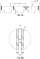
- the anvils 14A, 14B may each be provided with an anvil insert 24 having a predetermined profile.
- the anvil insert 24 illustrated in these views includes a pair of spaced apart seal surfaces 26 having a recess 28 therebetween and wherein the seal surfaces 26 are provided with a series of canted rectangular patterns or teeth 32 thereon.
- the canted orientation of the rectangular pattern 32 provides both trailing edge and leading-edge coverage in a cross-machine direction.
- the canted arrangement of the rectangles or teeth 32 creates a bond pattern that will evenly wear a corresponding ultrasonic horn 16A, 16B.
- the edges 34 of adjacent teeth 32 are parallel to one another and are angled relative to the machine direction at a predetermined angle 36 (see FIG. 5B ) that provides a following tooth 32 to fill in any gaps G (see FIG. 5C ) existing between any preceding tooth 32.
- the predetermined angle 36 may provide full coverage of the ultrasonic horn 16A, 16B to achieve the goal of even wear.
- the anvil insert 24 of these views may be used to simultaneously bond adjacent article end portions 38 with cross-machine direction bonds 40, as shown in FIGS. 6A and 6B , while reserving a boundary between the sealed end portions for a later severing operation.
- FIGS. 7, 8A, and 8B An alternative embodiment of an anvil insert A is illustrated in FIGS. 7, 8A, and 8B .
- the anvil insert 42 includes a seal surface 44 having a plurality of raised seal areas 46 arranged in a pattern that is canted from the machine direction at an angle 48.
- the pattern shown in FIGS. 8A and 8B may be applied to the entire surface of anvil 14A, 14B.
- FIG. 10 illustrates an alternative arrangement of anvils and ultrasonic horns.
- anvil pairs 14A1, 14A2 and 14B1, 14B2 are utilized rather that the single anvils 14A, 14B, illustrated in previous views.
- Ultrasonic horn pairs 16A1, 16A2 and 16B1, 16B2 correspond to and cooperate with the anvil pairs 14A1, 14A2 and 14B 1, 14B2.
- the predetermined distance d1 of the spacing of the first and second anvils 14A, 14B may be controlled to define the distance between the resulting bonds 40 on the web 12 ( FIGS. 6A and 6B ), with the resulting bonds 40 being located at what is to be an end portion 38 of an individual finished article ( FIGS. 6A and 6B ).
- the predetermined distance d1 may be changed to accommodate various sizes of the finished product, since the distance d1 corresponds to the length of the individual article. Accordingly, the length of the individual article may be changed by adjusting the position of the first or second ultrasonic horn 16A, 16B with respect to the other ultrasonic horn 16A, 16B.
- the system 10 is configured to change the distance between a selected anvil 14A, 14B and horn 16A, 16B and the adjacent anvil 14A, 14B and horn 16A, 16B (e.g., from d1 to d2) via operation of a device for linear reciprocation of a selected anvil 14A, 14B and ultrasonic horn 16A, 16B relative another anvil 14A, 14B and ultrasonic horn 16A, 16B and to move in the direction of arrow B, (see FIG. 2 ), with drive devices 50, such as electric motors, pneumatic actuators, or hydraulic actuators for example, and associated linear actuators 52 providing such linear reciprocation in the embodiment of FIGS. 1 and 2 .
- drive devices 50 such as electric motors, pneumatic actuators, or hydraulic actuators for example
- the selected anvil 14A, 14B and ultrasonic horn 16A, 16B combination is slidingly mounted to a base structure 54 to provide for linear translation thereof. Since the distance d1, d2 intervals of bonding positions may be changed by changing the position of the first or second ultrasonic horn 16A, 16B, the present system may easily produce individual articles of various sizes. It is to be understood that while the view of FIG. 2 illustrates movement of the second ultrasonic horn 16B, the position of the first ultrasonic horn 16A may also or alternatively be changeable, as required by a specific application.
- the distance d1, d2 between a selected anvil 14A, 14B and horn 16A, 16B and the adjacent anvil 14A, 14B and horn 16A, 16B may be controlled via a closed-loop control system 56.
- the control system 56 may operate one or more electric motors 50A, 50B for linearly translating a desired anvil and horn pair 14A, 14B, 16A, 16B along base structure 54, along with a vision system (e.g., camera) 58 that provides input to the control system 56 regarding positioning/spacing of the anvil and horn pairs 14A, 14B, 16A, 16B.
- a vision system e.g., camera
- the vision system 58 acquires images of bonding system 10 - and specifically of the positioning of anvils 14A, 14B and horns 16A, 16B on base structure 54.
- the vision system 58 provides these images as an input to control system 56, which may include a processor 60 therein that analyzes the images to determine therefrom a spacing between the anvil and horn pairs 14A, 14B, 16A, 16B.
- the processor 60 compares the spacing between the anvil and horn pairs 14A, 14B, 16A, 16B to a pre-determined desired spacing between the anvil and horn pairs (as set based on a size of the finished product and the spacing/location of bonds to be formed thereon).
- the spacing between the anvil and horn pairs 14A, 14B, 16A, 16B is the same as the pre-determined desired spacing, then the positioning of the anvil and horn pairs 14A, 14B, 16A, 16B is left unchanged. Conversely, if the spacing between the anvil and horn pairs 14A, 14B, 16A, 16B is different from the pre-determined desired spacing, then the positioning of one or more of the anvil and horn pairs 14A, 14B, 16A, 16B is changed so as to adjust the spacing therebetween.
- the control system 56 causes one or more of the electric motors 50A, 50B to operate its associated linear actuator 52A, 52B to cause linear translation or sliding of anvil and horn pair(s) 14A, 14B, 16A, 16B along base structure 54.
- continuous feedback may be acquired from vision system 58 until it is determined that spacing between the anvil and horn pairs 14A, 14B, 16A, 16B matches the pre-determined desired spacing thereof - at which time activation of the electric motors 50A, 50B is terminated.
- the above described closed-loop control system 56 provides for adjustment of the distance d1, d2 between the anvil and horn combinations 14A, 16A 14B, 16B at start-up of the system 10 and/or during operation of the system 10.
- vision system 58 may operate to acquire images of the positioning of anvil and horn pairs 14A, 14B, 16A, 16B that are subsequently utilized by an operator to manually alter positioning thereof. That is, vision system 58 provides images to processor 60, which analyzes the images to determine spacing between the anvil and horn pairs 14A, 14B, 16A, 16B and then provides the determined spacing as an output to an operator, such as a displayed numerical output.
- the operator may then control spacing between the anvil and horn pairs 14A, 14B, 16A, 16B by manually controlling one or more of electric motors 50A, 50B to operate its associated linear actuator 52A, 52B to cause linear translation or sliding of anvil and horn pair(s) 14A, 14B, 16A, 16B along base structure.
- the operator may alter the positioning of one or more of the anvil horn pairs 14A, 14B, 16A, 16B via use of +/- buttons included on control system 56.
- the positioning of one or more of the anvil horn pairs 14A, 14B, 16A, 16B may be incrementally adjusted until it is determined by vision system 58/ control system 56 that spacing between the anvil and horn pairs 14A, 14B, 16A, 16B matches the predetermined desired spacing thereof.
- an alternative embodiment of bonding system 10 additionally includes a third anvil 14C, provided with an anvil insert 24 having a predetermined profile as described above, and a third ultrasonic horn 16C.
- the anvils 14A, 14B, 14C are laterally spaced apart inline and in a machine direction 16.
- the ultrasonic horns 16A, 16B, 16C apply vibration energy to the web 12 simultaneously and in cooperation with a respective anvil 14A, 14B, 14C to bond a respective portion of the web 12 that is to be an end portion 38 of an individual finished article 12 ( FIGS. 6A and 6B ).
- the anvils 14A, 14B, 14C with the corresponding horns 16A, 16B, 16C are spaced apart a predetermined distance d3 that corresponds to the distance between bonds 40 on the finished article 12 (see FIGS. 6A and 6B ). Accordingly, the length of the individual article may be changed by adjusting the position of the first, second, or third ultrasonic horn 16A, 16B, 16C with respect to any other ultrasonic horn 16A, 16B, 16C.
- the bonding system 10 may include any combination of fixed and moveable ultrasonic horns 16A, 16B, 16C, such as, but not limited to: one fixed ultrasonic horn with two movable ultrasonic horns; two fixed ultrasonic horns and one movable ultrasonic horn; three fixed ultrasonic horns; and three movable ultrasonic horns, by way of non-limiting example.
- one or more selected anvils 14A, 14B, 14C and ultrasonic horns 16A, 16B, 16C may thus be linearly reciprocated relative to other anvils 14A, 14B, 14C and ultrasonic horns 16A, 16B, 16C, as indicated by arrow D, to thereby change the distance from d3 to d4 ( FIG. 12 ) between a selected anvil 14A, 14B, 14C and horn 16A, 16B, 16C and the adjacent anvil 14A, 14B, 14C and horn 16A, 16B, 16C.
- Such movement of the anvils 14A, 14B, 14C and ultrasonic horns 16A, 16B, 16C may be controlled via operation of electric motors 50 and associated linear actuators 52 by control system 56, in a similar manner as described above relative to FIGS. 1 and 2 .
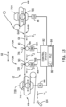
- a bonding system 62 is illustrated according to another embodiment where movement of the anvil (e.g., rotational speed/velocity thereof) is selectively controlled to be brought into phase with a speed of the web, in order to control the anvil dwell time against the web. While the system 62 (and technique for operation thereof) is described below relative to an ultrasonic bonding system and ultrasonic bonding technique that utilize an anvil and ultrasonic horn combination, it is contemplated that the system/technique described below may be extended to any other known thermal or pressure bonding system that utilizes an anvil for bonding on a moving web.
- a bonding system that forms pressure welds via interaction of a patterned anvil and a smooth roller (instead of an ultrasonic horn) and the use of active or passive thermal heating, is considered to be within the scope of the invention.
- the system 62 is described below with regard to controlling a bonding system that uses two bonding apparatuses (i.e., horn/anvil combinations), it is recognized that a system 62 could also be implemented having more than two bonding apparatuses or only a single bonding apparatus.
- a web of material 64 - formed from a first web layer 64A and a second web layer 64B (as described hereafter) or from a unitary web structure that is folded - is fed in the machine direction 66.
- the layers of web 64 are materials capable of fusing to one another upon application of an applied energy that causes one or both of the layers 64A, 64B to soften or melt and join together without the use of an intermediate layer of adhesive material such as glue.
- the facing pair of web layers 64A, 64B may be the same type of material or different materials according to alternative embodiments.
- first and second web layers 64A, 64B may include nonwoven materials, woven materials, films, foams, and/or composites or laminates of any of these material types.
- Bonding system 62 includes a velocity changing feeding assembly 68 (or more generally “velocity changing device”) that feeds the web 12 to one or more bonding apparatuses and controls a velocity thereof, with the one or more bonding apparatuses being, for example, two bonding apparatuses 70A, 70B shown in FIG. 13 - although it is recognized that only a single bonding apparatus may be included in the system 62.
- the velocity changing device 68 comprise operates to increase and decrease the moving velocity of the web 64 - with it being recognized that the velocity-changing device may comprise any of web festoon accumulators, a vertical accumulator series, or a horizontal accumulator series, for example, although web festoon accumulators are specifically illustrated in FIG. 13 .
- velocity changing device 68 includes a first web festoon accumulator 72A having a first accumulator roller 74A, and a second web festoon accumulator 72B having a second accumulator roller 74B.
- the first web festoon accumulator 72A receives the web 64 flowing from an upstream side and releases the webs toward the bonding apparatuses 70A, 70B while the second web festoon accumulator 72B receives the web 64 from the bonding apparatuses 70A, 70B and moves the web 64 toward a downstream side.
- the velocity-changing device 68 further includes means (e.g., linear actuator 88) for moving the first and second accumulator rollers 74A, 74B in a unison, linear manner to thereby change the velocity of the web 64 that is received from an initial velocity V1 (i.e., a "feed velocity").
- V1 initial velocity
- the spacing between first and second accumulator rollers 74A, 74B may be adjusted to change the velocity to a second, slower velocity V2 for performing bonding of the web 64 (i.e., a "bonding velocity"), such that the dwell time of the web 64 during the bonding operation is adequate for proper bonding.
- the spacing between first and second accumulator rollers 74A, 74B may also be adjusted to change the velocity to a velocity V3 once the web 64 is bonded, before being transported by the second web festoon accumulator 72B again at the first V1 velocity.
- the bonding apparatuses 70A, 70B of bonding system 62 may be any known ultrasonic welding systems in alternative embodiments, including, as non-limiting examples, a rotary ultrasonic welding system or a blade ultrasonic welding system.
- bonding apparatuses 70A, 70B each include a rotary anvil 76A, 76B and an ultrasonic fixed blade horn 78A, 78B, also known as a sonotrode, which cooperate with each other to bond (i.e., fuse) the first web layer 64A to the second web layer 64B.
- Alternative embodiments may include multiple fixed blade horns or one or more rotary horns.
- a motor (not shown) that drives the ultrasonic horn 78A, 78B and a vibration control unit (not shown) that ultrasonically energizes the horn 78A, 78B and causes the horn to vibrate are also included in bonding apparatus, as well as an anvil actuator 80A, 80B operatively coupled to each anvil 76A, 76B to drive the anvil 76A, 76B.
- the anvil actuators 80A, 80B may be configured as servo motors (and are thus hereafter referred to as "servo motors 80A, 80B"), but it is recognized that the anvil actuators 80A, 80B may be any suitable device that effects actuation of the anvils 76A, 76B.
- each bonding apparatus 70A, 70B are positioned in a spaced relationship relative to one another to facilitate ultrasonically bonding the first and second web layers 64A, 64B to one another.
- the web layers 64A, 64B are exposed to an ultrasonic emission from the horn 78A, 78B that increases the vibration of the particles in the web layers 64A, 64B.
- the ultrasonic emission or energy is concentrated at specific bond points where frictional heat fuses the web layers 64A, 64B together without the need for consumable adhesives.
- a control system 82 is included in bonding system 62 that functions to control operation of the bonding apparatuses 70A, 70B and the velocity changing device 68.
- the control system 82 may comprise a programmable logic controller 84 operably connected to the bonding apparatuses 70A, 70B and the velocity changing device 68 via wired or wireless connections that provide for the communication of signals (inputs, control signals, etc.) therebetween.
- the programmable logic controller 84 includes one or more processors 86 for processing data acquired during operation of bonding systems 70A, 70B and/or for generating command signals that control operation of bonding apparatuses 70A, 70B and the velocity changing device 68.
- control system 82 is in operable communication with velocity changing device 68 in order to selectively control a velocity of the web 64 as it is provided to the bonding apparatuses 70A, 70B from the velocity changing device 68.
- control system 82 is in operable communication with linear actuators 88 of the web festoon accumulators that position first and second accumulator rollers 74A, 74B, so as to selectively control operation of the linear actuators 88 and thereby control the velocity of the web 64.
- first and second accumulator rollers 74A, 74B may be moved to thereby change the velocity of the web 64 from an initial velocity V1 to a second, slower velocity V2 during bonding of the web 64 and to a velocity V3 once the web 64 is bonded, before being transported by the second web festoon accumulator 72B again at the first V1 velocity.
- the control system 82 is also in operable communication with bonding apparatuses 70A, 70B in order to selectively control the motors (not shown) that drive the ultrasonic horns 78A, 78B and the vibration control units (not shown) that ultrasonically energizes the horns 78A, 78B and causes the horns 78A, 78B to vibrate, as well as control servo motors 80A, 80B to drive the anvils 76A, 76B.
- the control system 82 transmits control signals to servo motors 80A, 80B to control a movement of the anvils 76A, 76B, such as by setting a rotational speed or velocity of the rotary anvils 76A, 76B in the embodiment of FIG. 13 .
- the velocity may be varied to thereby influence the dwell time of the anvils 76A, 76B (i.e., anvil insert 90, which may be configured as insert 24 shown in FIGS. 4A, 4B , 5A, 5B, 5C , for example) against the web 64.
- the revolution speed of the anvils 14A, 14B is varied such that, the revolution speed of the anvils 14A, 14B from the upstream side may be slowed to second, slower velocity, such that the dwell time of the web 64 during the bonding operation is adequate for proper bonding.
- the anvils 14A, 14B accelerate to an increased velocity to be rotated back to the first velocity, and in a downstream direction.
- control system 82 controls operation of the velocity changing device 68 and bonding apparatuses 70A, 70B such that the velocity/speed of the web 64 is phased with the velocity/speed of the anvils 76A, 76B. That is, control system 82 controls operation of the velocity changing device 68 and bonding apparatuses 70A, 70B such that increases in a velocity of the web 64 correspond to increases in a velocity of the anvils 76A, 76B, and likewise decreases in a velocity of the web 64 correspond to decreases in a velocity of the anvils 76A, 76B.
- the dwell time of the anvils 76A, 76B against the web 64 can be selectively controlled, such as the dwell time being maximized when desired.
- the controlling of the dwell time of the anvils 76A, 76B against the web 64 allows for bonds of a desired length (in the machine direction 66) to be formed on the web 64, with the length of the bonds being selectively controllable based on product type/size, web materials, and the strength of the bonds that is required. Referring back to FIGS. 6A and 6B , bonds 40 are shown therein in greater detail, with it being seen in the close-up view of FIG.
- the length 92 of each of the bonds 40 in the bond pattern may be selectively controlled based on the dwell time of the anvils 76A, 76B against the web 64, as determined at least in part by the velocity/speed of the web 64 and the velocity/speed of the anvils 76A, 76B. Additionally, by varying the length 92 of adjacent bonds 40, a spacing 94 between bonds 40 can also be selectively controlled. According to an embodiment, the length 92 of bonds 40 and/or spacing 94 between bonds 40 can be varied by as much as 25% by controlling the dwell time of the anvils 76A, 76B against the web 64.
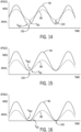
- FIGS. 14-16 illustrate velocity profiles of the web 64 and anvils 76A, 76B as controlled by control system 82, with the control system 82 controlling velocity changing device 68 and anvils 76A, 76B to synchronize the velocities of the web 64 and anvils 76A, 76B.
- the web velocity 96 and anvil (rotational) velocity 98 are controlled to have a sinusoidal profile, with the velocity of the web 64 and anvils 76A, 76B being brought to a bonding speed/velocity, indicated as web bonding velocity V W 2 and anvil bonding velocity V A 2, at a desired frequency.
- web velocity 96 and anvil velocity 98 profiles are depicted as sinusoidal in FIGS. 14-16 , either or both of the velocity profiles could have a triangular, sawtooth, or other non-sinusoidal profile, according to alternative embodiments.
- the web velocity 96 and anvil velocity 98 are synchronized with one another, but the velocity of the web 64 and the anvils 76A, 76B are not equal to each other during a bonding period 100 when bonds are formed on the web 64. That is, control system 82 controls velocity changing device 68 and servo motor 80A, 80B such that web 64 is translated at a bonding velocity Vw2 that is greater than an anvil bonding velocity V A 2 at which the anvils 76A, 76B rotate.
- the magnitude of the velocity mismatch between the web bonding velocity V W 2 and the anvil bonding velocity V A 2, indicated at 102, determines (in part) a length of the bonds formed on the web 64, as it impacts a dwell time of the web on the anvil, and this magnitude of the velocity mismatch 102 can be selectively controlled by an operator to thereby control the bond length.
- velocity profiles of the web 64 and anvils 76A, 76B are shown according an embodiment where the speeds/velocities of the web 64 and anvils 76A, 76B are synchronized during a bonding period 100 when bonds are formed on the web 64 such that they are made equal or substantially equal (e.g., +/- 5%) in magnitude during the bonding period 100. Stated another way, the velocity mismatch between the web velocity and the anvil velocity is brought to zero or substantially zero.
- Such synchronizing of the web velocity 96 and anvil velocity 98 at equal speeds enable the formation of "full" bonds on the web 64 having desirable bond strength.
- both the web velocity 96 and the anvil velocity 98 may be reduced to zero during a bonding period 100 when bonds are formed on the web 64 (i.e., "zero-speed bonding"), as shown in FIG. 16 .
- the term zero-speed bonding as used herein refers to an embodiment where the web velocity 96 and the anvil velocity 98 are reduced to zero (i.e., not moving) during bonding of the web 64 or are reduced essentially to zero during bonding of the web 64 - such as at a velocity of 0-200 m/min.
- the implementing of zero-speed bonding in bonding system 62 provides for the formation of straight bond lines on the web 64, which may be desirable from both a strength standpoint and an aesthetic standpoint.
- bonding system further comprises a vision system or systems 104 operatively coupled to control system 82 to provide feedback thereto regarding the bonds formed on web 64.
- the vision systems 104 may comprise high-speed cameras or other image capturing devices that are configured to acquire images of the bonds formed by bonding apparatuses 70A, 70B.
- a vision system 104 may be provided for each bonding apparatus 22 to acquire such bond images.
- the vision systems 104 provide the acquired image(s) to a processor 86 of control system 82, which analyzes the image(s) in order to determine a length of the bonds in the machine direction.
- the determined length of the bonds may be used for a number of different control purposes, including determining that the bonds being formed by bonding apparatuses 70A, 70B are of a desired length and/or when making an adjustment from an existing bond length to a new bond length and identifying when the bond length has been achieved.
- control system 82 operates as a closed-loop system utilizing the acquired image(s) as an input in order to selectively control operation of the servo motors 80A, 80B, for purposes of adjusting the rotational speed/velocity of the anvils 76A, 76B and thereby controlling a length of the bonds.
- the closed-loop control technique implemented by control system 82 allows for on-the-fly adjustments of bonding system 62 during operation thereof, whether it be to correct an identified error in the bonding and/or adjust the bond length to a desired value responsive to a changing of materials or a change of product size. Such adjustments can be made without having to change tooling in bonding system 62, but instead can be achieved via controlling of the anvil rotational speed/velocity in order to artificially change the bond length on web 64.
- FIG. 17 a flowchart illustrating a closed-loop control technique 110 implemented by control system 82 for controlling movement/speed of the web 64 and anvils 76A, 76B is provided, according to an embodiment of the invention. While the technique 110 is described below with regard to controlling a bonding system 62 that uses multiple bonding apparatuses 70A, 70B (i.e., horn/anvil combinations), it is recognized that the technique could also be used to control a system that utilizes only a single bonding apparatus. As shown in FIG. 17 , technique 110 begins at STEP 112 with an input being provided to control system 82 regarding a pre-determined bond length (in the machine direction) to be formed on web 64 for bonding together layers 64A, 64B of the web.
- a pre-determined bond length in the machine direction
- control system 82 Upon input of the predetermined bond length, control system 82 operates to generate and send command signals to velocity changing device 68 and bonding apparatuses 70A, 70B (i.e., to servo motors 80A, 80B) in order to cause web 64 and anvils 76A, 76B to move according to an initial velocity profile, as indicated at STEP 114.
- the web velocity 96 and anvil (rotational) velocity 98 may be controlled to have a sinusoidal profile, with the velocity of the web 64 and anvils 76A, 76B being phased with one another and having varying speeds/velocities during bonding and non-bonding periods.
- the web velocity 96 and anvil velocity 98 are in-phase with one another but unequal during a bonding period when bonds are formed on the web 64, while in another embodiment the web velocity 96 and anvil velocity 98 are synchronized with one another (i.e., equal) during the bonding period.
- control system 82 Upon bonding system 62 beginning to operate under initial settings implemented by control system 82, the technique continues at STEP 116 with vision systems 104 acquiring images of bonds formed by bonding apparatuses 70A, 70B and subsequently providing said images to the control system 82 as input/feedback.
- a processor 86 of control system 82 analyzes the images in order to determine a length of the bonds in the machine direction and, at STEP 118, determines whether the bond length matches the length set by the operator.
- control system 82 sending modified control signals to the servo motors 80A, 80B that drive anvils 76A, 76B, so as to vary the movement/rotational velocity thereof.
- the modified control signals cause an adjustment of the movement/rotational velocity of the anvils 76A, 76B, at least during a bonding period of the web 64, such that a velocity mismatch between the web 64 and the anvils 76A, 76B is also modified.
- the altering of the velocity mismatch causes a corresponding change in the length of the bonds formed on web 64.
- the technique 110 Upon completion of STEP 122, the technique 110 then loops back to STEPS 116 and 118 with the vision systems 104 acquiring and transmitting images of bonds to the control system 82 as input/feedback, and the control system 82 determining whether the bond length matches the length set by the operator.
- the revised inputs may be in the form of input provided to control system 82 via an operator input, for example, and may be based on a change in a size/type of product to be processed on bonding system 62, a change in web materials, and/or a change in the desired bond length/strength to be formed on web 64.
- the revised inputs are deemed to necessitate a change in the bond length formed by bonding apparatus(es).
- control system 82 send modified control signals to the servo motors 80A, 80B that drive anvils 76A, 76B (and optionally to velocity changing device 68) so as to vary the movement/rotational velocity thereof in accordance with the revised inputs.
- the modified control signals cause an adjustment of the movement/rotational velocity of the anvils 76A, 76B (and web 64), at least during a bonding period of the web 64, such that a velocity mismatch between the web 64 and the anvils 76A, 76B is also modified.
- the altering of the velocity mismatch causes a corresponding change in the length of the bonds formed on web 64.
- the technique then loops back to STEPS 116 and 118 with the vision systems 104 acquiring and transmitting images of bonds to the control system 82 as input/feedback, and the control system 82 determining whether the bond length matches the pre-determined length set by the operator.
- technique loops back to STEPS 116 and 118 with the vision systems 104 acquiring and transmitting images of the bonds to the control system 82 as input/feedback, and the control system 82 determining whether the bond length matches the bond length set by the operator. That is, the control system 82 monitors operation of the bonding system to confirm that the bonds being formed on web 64 continue to match the bonds desired in the initial input settings provided to the control system 82.
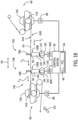
- a bonding system 136 is illustrated according to another embodiment that includes one or more cammed or "wobble" anvils that follow a predetermined cyclical velocity profile.
- the cammed anvils 138A, 138B may be used in bonding system 136 instead of rotary anvils 76A, 76B as depicted in FIG. 13 , with the cammed anvils 138A, 138B beneficially providing for a faster cycling time and/or enabling low speed operation of the bonding system 136 (i.e., low web speed and anvil movement/speed).
- Each cammed anvil 138A, 138B includes a cam wheel 140 having a cam track or surface 142 formed therein, a cam member 144 that translates within/around the cam track 142 when the cam wheel is rotated, and an anvil body 146 attached to the cam member 144 so as to translate therewith - with the anvil body 146 presenting a surface that interacts with horn 78A, 78B to enable the formation of ultrasonic bonds on web 64.
- the cam track 142 may comprise an irregular or oblong track in which the cam member 144 rides. As the cam member 144 rides along cam track 142, the anvil body 146 is caused to move therewith, with movement of the anvil body 146 comprising both vertical (up/down) movement and horizontal movement.
- the horizontal movement is in the machine direction when the anvil body 146 is proximate the horn 78A, 78B to form bonds on the web 64 via interaction of the anvil body and horn, as some horizontal movement of the anvil body 146 in the machine direction 66 is necessary when forming bonds with a web 64 moving at a web velocity in the machine direction.
- the anvil body 146 may exhibit only vertical movement, as horizontal movement/rotation of the anvil body 146 would not be necessary in such an embodiment.
- a servo motor 80A, 80B operably connected to the cammed anvil 138A, 138B causes wheel 140 to rotate, thereby causing the cam member 144 to ride in the cam track 142 and cause cyclical displacement of the anvil body 146 relative to the horn 78A, 78B at a desired frequency and speed.
- control system 82 controls operation of servo motors 80A, 80B to phase the movement/rotational velocity of cammed anvils 138A, 138B with the movement/velocity of the web 64.
- the velocity profiles of the web 64 and anvils 138A, 138B may be controlled by control system 82 to match any of the profiles shown in FIGS. 14-16 , for example, and may thus be controlled as phased movements/velocities, as synchronized movements/velocities, or according to a zero-speed bonding control.
- embodiments of the invention thus provide an apparatus and method for controlling the speed of both a continuous web and a bonding apparatus in order to effectuate stronger bonds in the web, including phasing and/or synchronization of these speeds at a desired bonding time.
- An anvil in each of one or more anvil/horn combinations is selectively driven by a servo motor such that the movement/velocity thereof is phased with the movement/velocity of the web that is being bonded.
- the dwell time of the anvil(s) against the web can be selectively controlled, such as the dwell time being maximized when desired.
- the controlling of the dwell time of the anvil(s) against the web allows for bonds of a desired length (in the machine direction) to be formed on the web, with the length of the bonds being selectively controllable based on product type/size, web materials, and the strength of the bonds that is required.
- Embodiments also beneficially provide a system for selectively controlling the distance between a selected anvil and horn and the adjacent anvil and horn.
- a vision system may acquire data on the distance between adjacent anvil-horn combinations, with the data used in a closed-loop control system where a control system causes a motor and associated linear actuator to selectively adjust a position of one or more anvil-horn combinations or the data being provided to an operator to enable the operator to actively control a motor and associated linear actuator to selectively adjust a position of one or more anvil-horn combinations.
- a system for bonding a web comprising at least a pair of web layers includes a velocity changing device for increasing and decreasing a velocity of the web in a machine direction, an anvil and a corresponding ultrasonic horn that interact to form ultrasonic bonds on the web, and an anvil actuator configured to control a movement of the anvil.
- a control system is also included in the bonding system for controlling operation of the anvil actuator the velocity changing device, with the control system programmed to decrease a moving velocity of the web from a feed velocity to a bonding velocity as the web passes between the anvil and the ultrasonic horn and control movement of the anvil to synchronize the movement of the anvil with the moving velocity of the web.
- a method for bonding a web having at least a pair of web layers includes moving a web in a machine direction via a feeding assembly, the feeding assembly configured to selectively control a velocity of the web.
- the method also includes feeding the web to one or more bonding apparatuses, each of the one or more bonding apparatuses comprising an anvil, an ultrasonic horn that interacts with the anvil to form ultrasonic bonds on the web, and an anvil actuator configured to control a velocity of the anvil.
- the method further includes controlling operation of the anvil actuator and the feeding assembly to synchronize the velocity of the web with a velocity of the anvil by decreasing the velocity of the web and the velocity of the anvil to a web bonding velocity and an anvil bonding velocity as the web passes between the anvil and the ultrasonic horn.
Landscapes
- Engineering & Computer Science (AREA)
- Mechanical Engineering (AREA)
- Health & Medical Sciences (AREA)
- Life Sciences & Earth Sciences (AREA)
- Epidemiology (AREA)
- Biomedical Technology (AREA)
- Heart & Thoracic Surgery (AREA)
- Vascular Medicine (AREA)
- Manufacturing & Machinery (AREA)
- Animal Behavior & Ethology (AREA)
- General Health & Medical Sciences (AREA)
- Public Health (AREA)
- Veterinary Medicine (AREA)
- Absorbent Articles And Supports Therefor (AREA)
- Lining Or Joining Of Plastics Or The Like (AREA)
- Die Bonding (AREA)
Applications Claiming Priority (1)
| Application Number | Priority Date | Filing Date | Title |
|---|---|---|---|
| US16/508,422 US11192310B2 (en) | 2019-07-11 | 2019-07-11 | Method and apparatus for improved ultrasonic bonding |
Publications (2)
| Publication Number | Publication Date |
|---|---|
| EP3763343A1 EP3763343A1 (en) | 2021-01-13 |
| EP3763343B1 true EP3763343B1 (en) | 2023-04-12 |
Family
ID=71409314
Family Applications (1)
| Application Number | Title | Priority Date | Filing Date |
|---|---|---|---|
| EP20183372.0A Active EP3763343B1 (en) | 2019-07-11 | 2020-07-01 | Method and apparatus for improved ultrasonic bonding |
Country Status (8)
| Country | Link |
|---|---|
| US (2) | US11192310B2 (da) |
| EP (1) | EP3763343B1 (da) |
| JP (1) | JP7715366B2 (da) |
| CA (1) | CA3085036A1 (da) |
| DK (1) | DK3763343T3 (da) |
| ES (1) | ES2946612T3 (da) |
| MX (1) | MX2020007440A (da) |
| PL (1) | PL3763343T3 (da) |
Families Citing this family (1)
| Publication number | Priority date | Publication date | Assignee | Title |
|---|---|---|---|---|
| WO2025114583A2 (en) * | 2023-11-30 | 2025-06-05 | Curt G Joa, Inc. | Systems and methods for manufacturing dry molded fiber components |
Citations (1)
| Publication number | Priority date | Publication date | Assignee | Title |
|---|---|---|---|---|
| EP1477293B1 (en) * | 2003-05-12 | 2015-08-19 | Illinois Tool Works Inc. | Ultrasonic apparatus with non-rotating horn and rotating anvil for welding plastic parts |
Family Cites Families (27)
| Publication number | Priority date | Publication date | Assignee | Title |
|---|---|---|---|---|
| US3993532A (en) | 1974-11-11 | 1976-11-23 | Consolidated Engravers Corporation | Ultrasonic sealing pattern roll |
| TW253870B (en) | 1994-07-11 | 1995-08-11 | Newell Operating Co | Cellular panel and method and apparatus for making the same |
| US6123792A (en) * | 1998-08-14 | 2000-09-26 | Kimberly-Clark Worldwide, Inc. | Methods and apparatus for intermittent rotary ultrasonic bonding system |
| US6585836B2 (en) | 2000-07-11 | 2003-07-01 | Sumitomo Wiring Systems, Ltd. | Flat cable and a manufacturing method thereof |
| US6454890B1 (en) | 2000-11-30 | 2002-09-24 | Kimberly-Clark Worldwide, Inc. | Method and apparatus for up to full width ultrasonic bonding |
| EP1344639A3 (en) | 2002-03-12 | 2004-04-28 | SCA Hygiene Products GmbH | Web embossing unit |
| US7082347B2 (en) * | 2002-08-07 | 2006-07-25 | Kimberly-Clark Worldwide, Inc. | Autosetpoint registration control system and method associated with a web converting manufacturing process |
| US7204899B2 (en) | 2003-04-30 | 2007-04-17 | Kimberly-Clark Worldwide, Inc. | Apparatus and method for mechanically bonding and cutting an article |
| JP4361562B2 (ja) | 2004-02-25 | 2009-11-11 | 株式会社瑞光 | ウエブの溶着システム |
| US7971526B2 (en) | 2006-04-17 | 2011-07-05 | Kimberly-Clark Worldwide, Inc. | Embossing or bonding device containing facetted impression elements |
| JP5508061B2 (ja) | 2009-03-02 | 2014-05-28 | ユニ・チャーム株式会社 | 接合装置及び吸収性物品の製造方法 |
| JP5475355B2 (ja) | 2009-07-31 | 2014-04-16 | ユニ・チャーム株式会社 | 超音波接合装置及び吸収性物品の製造装置 |
| JP5728214B2 (ja) | 2010-12-10 | 2015-06-03 | 花王株式会社 | 超音波接合装置、それを用いたウエブの接合方法及びそれを用いたパンツ型着用物品の製造方法 |
| JP5836032B2 (ja) * | 2011-09-22 | 2015-12-24 | ユニ・チャーム株式会社 | 吸収性物品に係る積層体の圧搾部の検査装置、及び検査方法 |
| JP5936408B2 (ja) | 2012-03-26 | 2016-06-22 | 株式会社リブドゥコーポレーション | ヒートシール装置 |
| JP5904587B2 (ja) | 2012-07-31 | 2016-04-13 | 大王製紙株式会社 | 超音波シール装置、超音波シール方法、及び超音波シールにおけるクリアランス調整方法 |
| JP5089821B1 (ja) * | 2012-07-31 | 2012-12-05 | 新興機械株式会社 | シール装置 |
| US9149980B2 (en) | 2012-08-02 | 2015-10-06 | Frito-Lay North America, Inc. | Ultrasonic sealing of packages |
| JP2014097097A (ja) * | 2012-11-13 | 2014-05-29 | Zuiko Corp | ウエブの溶着システムおよび溶着方法 |
| JP6155031B2 (ja) | 2013-01-30 | 2017-06-28 | ユニ・チャーム株式会社 | 吸収性物品に係るシート状部材の溶着装置、及び溶着方法 |
| JP5572239B1 (ja) | 2013-03-08 | 2014-08-13 | 花王株式会社 | 搬送経路の転換装置 |
| US9144624B2 (en) | 2013-07-19 | 2015-09-29 | The Procter & Gamble Company | Method for providing a localized dwell in an advancing web |
| WO2018012210A1 (ja) * | 2016-07-11 | 2018-01-18 | 株式会社瑞光 | 超音波溶着装置及び超音波溶着方法 |
| JP6279024B2 (ja) | 2016-07-27 | 2018-02-14 | ブランソン・ウルトラソニックス・コーポレーション | 超音波溶着用アンビル |
| ES2891856T3 (es) * | 2016-09-15 | 2022-01-31 | Joa Curt G Inc | Pegadora dual |
| US10561539B2 (en) * | 2016-09-15 | 2020-02-18 | Curt G. Joa, Inc. | Dual bonder |
| US20190060135A1 (en) * | 2017-08-30 | 2019-02-28 | The Procter & Gamble Company | Method and Apparatus for Manufacturing an Absorbent Article |
-
2019
- 2019-07-11 US US16/508,422 patent/US11192310B2/en active Active
-
2020
- 2020-06-30 CA CA3085036A patent/CA3085036A1/en active Pending
- 2020-07-01 DK DK20183372.0T patent/DK3763343T3/da active
- 2020-07-01 PL PL20183372.0T patent/PL3763343T3/pl unknown
- 2020-07-01 ES ES20183372T patent/ES2946612T3/es active Active
- 2020-07-01 EP EP20183372.0A patent/EP3763343B1/en active Active
- 2020-07-07 JP JP2020116839A patent/JP7715366B2/ja active Active
- 2020-07-13 MX MX2020007440A patent/MX2020007440A/es unknown
-
2021
- 2021-12-06 US US17/457,715 patent/US11813800B2/en active Active
Patent Citations (1)
| Publication number | Priority date | Publication date | Assignee | Title |
|---|---|---|---|---|
| EP1477293B1 (en) * | 2003-05-12 | 2015-08-19 | Illinois Tool Works Inc. | Ultrasonic apparatus with non-rotating horn and rotating anvil for welding plastic parts |
Also Published As
| Publication number | Publication date |
|---|---|
| EP3763343A1 (en) | 2021-01-13 |
| US20220088885A1 (en) | 2022-03-24 |
| JP2021014116A (ja) | 2021-02-12 |
| CA3085036A1 (en) | 2021-01-11 |
| MX2020007440A (es) | 2021-01-12 |
| US11192310B2 (en) | 2021-12-07 |
| US11813800B2 (en) | 2023-11-14 |
| ES2946612T3 (es) | 2023-07-21 |
| JP7715366B2 (ja) | 2025-07-30 |
| US20210008809A1 (en) | 2021-01-14 |
| PL3763343T3 (pl) | 2023-07-31 |
| DK3763343T3 (da) | 2023-05-30 |
Similar Documents
| Publication | Publication Date | Title |
|---|---|---|
| JP6871648B2 (ja) | デュアルボンダー | |
| EP3095589B1 (en) | A device for forming ultrasonic welds on web materials in continuous movement | |
| EP1609582B1 (en) | Seal device and seal method using the same | |
| CN103747767B (zh) | 超声密封设备和超声密封方法 | |
| CN111084693A (zh) | 一次性穿着物品的制造设备总成及其制造方法 | |
| US11000423B2 (en) | Dual bonder | |
| US9144624B2 (en) | Method for providing a localized dwell in an advancing web | |
| JP2021041161A (ja) | 捕捉機構付き湾曲弾性体 | |
| EP3763343B1 (en) | Method and apparatus for improved ultrasonic bonding | |
| US20140238210A1 (en) | Tissue perforating apparatus | |
| EP3870426B1 (en) | Dual bonder | |
| CN108430773A (zh) | 超声密封器 | |
| JP6568449B2 (ja) | シート融着体の製造方法及び製造装置 | |
| JP4093901B2 (ja) | 吸収性物品の製造方法及び製造装置 | |
| US11772332B2 (en) | Web welding system and welding method | |
| JP2004155586A (ja) | 配置装置 | |
| JP5155809B2 (ja) | 複合シートの製造方法 | |
| JP2019077063A (ja) | シート融着体の製造装置及び製造方法 | |
| WO2015195106A1 (en) | Tissue perforating apparatus |
Legal Events
| Date | Code | Title | Description |
|---|---|---|---|
| PUAI | Public reference made under article 153(3) epc to a published international application that has entered the european phase |
Free format text: ORIGINAL CODE: 0009012 |
|
| STAA | Information on the status of an ep patent application or granted ep patent |
Free format text: STATUS: THE APPLICATION HAS BEEN PUBLISHED |
|
| AK | Designated contracting states |
Kind code of ref document: A1 Designated state(s): AL AT BE BG CH CY CZ DE DK EE ES FI FR GB GR HR HU IE IS IT LI LT LU LV MC MK MT NL NO PL PT RO RS SE SI SK SM TR |
|
| AX | Request for extension of the european patent |
Extension state: BA ME |
|
| STAA | Information on the status of an ep patent application or granted ep patent |
Free format text: STATUS: REQUEST FOR EXAMINATION WAS MADE |
|
| 17P | Request for examination filed |
Effective date: 20210707 |
|
| RBV | Designated contracting states (corrected) |
Designated state(s): AL AT BE BG CH CY CZ DE DK EE ES FI FR GB GR HR HU IE IS IT LI LT LU LV MC MK MT NL NO PL PT RO RS SE SI SK SM TR |
|
| GRAP | Despatch of communication of intention to grant a patent |
Free format text: ORIGINAL CODE: EPIDOSNIGR1 |
|
| STAA | Information on the status of an ep patent application or granted ep patent |
Free format text: STATUS: GRANT OF PATENT IS INTENDED |
|
| INTG | Intention to grant announced |
Effective date: 20221024 |
|
| GRAS | Grant fee paid |
Free format text: ORIGINAL CODE: EPIDOSNIGR3 |
|
| GRAA | (expected) grant |
Free format text: ORIGINAL CODE: 0009210 |
|
| STAA | Information on the status of an ep patent application or granted ep patent |
Free format text: STATUS: THE PATENT HAS BEEN GRANTED |
|
| AK | Designated contracting states |
Kind code of ref document: B1 Designated state(s): AL AT BE BG CH CY CZ DE DK EE ES FI FR GB GR HR HU IE IS IT LI LT LU LV MC MK MT NL NO PL PT RO RS SE SI SK SM TR |
|
| REG | Reference to a national code |
Ref country code: GB Ref legal event code: FG4D |
|
| REG | Reference to a national code |
Ref country code: CH Ref legal event code: EP |
|
| REG | Reference to a national code |
Ref country code: DE Ref legal event code: R096 Ref document number: 602020009626 Country of ref document: DE |
|
| REG | Reference to a national code |
Ref country code: IE Ref legal event code: FG4D |
|
| REG | Reference to a national code |
Ref country code: AT Ref legal event code: REF Ref document number: 1559394 Country of ref document: AT Kind code of ref document: T Effective date: 20230515 |
|
| REG | Reference to a national code |
Ref country code: DK Ref legal event code: T3 Effective date: 20230522 |
|
| REG | Reference to a national code |
Ref country code: NL Ref legal event code: FP |
|
| P01 | Opt-out of the competence of the unified patent court (upc) registered |
Effective date: 20230528 |
|
| REG | Reference to a national code |
Ref country code: ES Ref legal event code: FG2A Ref document number: 2946612 Country of ref document: ES Kind code of ref document: T3 Effective date: 20230721 |
|
| REG | Reference to a national code |
Ref country code: SE Ref legal event code: TRGR |
|
| REG | Reference to a national code |
Ref country code: LT Ref legal event code: MG9D |
|
| REG | Reference to a national code |
Ref country code: AT Ref legal event code: MK05 Ref document number: 1559394 Country of ref document: AT Kind code of ref document: T Effective date: 20230412 |
|
| PG25 | Lapsed in a contracting state [announced via postgrant information from national office to epo] |
Ref country code: PT Free format text: LAPSE BECAUSE OF FAILURE TO SUBMIT A TRANSLATION OF THE DESCRIPTION OR TO PAY THE FEE WITHIN THE PRESCRIBED TIME-LIMIT Effective date: 20230814 Ref country code: NO Free format text: LAPSE BECAUSE OF FAILURE TO SUBMIT A TRANSLATION OF THE DESCRIPTION OR TO PAY THE FEE WITHIN THE PRESCRIBED TIME-LIMIT Effective date: 20230712 Ref country code: AT Free format text: LAPSE BECAUSE OF FAILURE TO SUBMIT A TRANSLATION OF THE DESCRIPTION OR TO PAY THE FEE WITHIN THE PRESCRIBED TIME-LIMIT Effective date: 20230412 |
|
| PG25 | Lapsed in a contracting state [announced via postgrant information from national office to epo] |
Ref country code: RS Free format text: LAPSE BECAUSE OF FAILURE TO SUBMIT A TRANSLATION OF THE DESCRIPTION OR TO PAY THE FEE WITHIN THE PRESCRIBED TIME-LIMIT Effective date: 20230412 Ref country code: LV Free format text: LAPSE BECAUSE OF FAILURE TO SUBMIT A TRANSLATION OF THE DESCRIPTION OR TO PAY THE FEE WITHIN THE PRESCRIBED TIME-LIMIT Effective date: 20230412 Ref country code: LT Free format text: LAPSE BECAUSE OF FAILURE TO SUBMIT A TRANSLATION OF THE DESCRIPTION OR TO PAY THE FEE WITHIN THE PRESCRIBED TIME-LIMIT Effective date: 20230412 Ref country code: IS Free format text: LAPSE BECAUSE OF FAILURE TO SUBMIT A TRANSLATION OF THE DESCRIPTION OR TO PAY THE FEE WITHIN THE PRESCRIBED TIME-LIMIT Effective date: 20230812 Ref country code: HR Free format text: LAPSE BECAUSE OF FAILURE TO SUBMIT A TRANSLATION OF THE DESCRIPTION OR TO PAY THE FEE WITHIN THE PRESCRIBED TIME-LIMIT Effective date: 20230412 Ref country code: GR Free format text: LAPSE BECAUSE OF FAILURE TO SUBMIT A TRANSLATION OF THE DESCRIPTION OR TO PAY THE FEE WITHIN THE PRESCRIBED TIME-LIMIT Effective date: 20230713 |
|
| PG25 | Lapsed in a contracting state [announced via postgrant information from national office to epo] |
Ref country code: FI Free format text: LAPSE BECAUSE OF FAILURE TO SUBMIT A TRANSLATION OF THE DESCRIPTION OR TO PAY THE FEE WITHIN THE PRESCRIBED TIME-LIMIT Effective date: 20230412 |
|
| REG | Reference to a national code |
Ref country code: DE Ref legal event code: R097 Ref document number: 602020009626 Country of ref document: DE |
|
| PG25 | Lapsed in a contracting state [announced via postgrant information from national office to epo] |
Ref country code: SK Free format text: LAPSE BECAUSE OF FAILURE TO SUBMIT A TRANSLATION OF THE DESCRIPTION OR TO PAY THE FEE WITHIN THE PRESCRIBED TIME-LIMIT Effective date: 20230412 |
|
| PG25 | Lapsed in a contracting state [announced via postgrant information from national office to epo] |
Ref country code: SM Free format text: LAPSE BECAUSE OF FAILURE TO SUBMIT A TRANSLATION OF THE DESCRIPTION OR TO PAY THE FEE WITHIN THE PRESCRIBED TIME-LIMIT Effective date: 20230412 Ref country code: SK Free format text: LAPSE BECAUSE OF FAILURE TO SUBMIT A TRANSLATION OF THE DESCRIPTION OR TO PAY THE FEE WITHIN THE PRESCRIBED TIME-LIMIT Effective date: 20230412 Ref country code: RO Free format text: LAPSE BECAUSE OF FAILURE TO SUBMIT A TRANSLATION OF THE DESCRIPTION OR TO PAY THE FEE WITHIN THE PRESCRIBED TIME-LIMIT Effective date: 20230412 Ref country code: EE Free format text: LAPSE BECAUSE OF FAILURE TO SUBMIT A TRANSLATION OF THE DESCRIPTION OR TO PAY THE FEE WITHIN THE PRESCRIBED TIME-LIMIT Effective date: 20230412 |
|
| PLBE | No opposition filed within time limit |
Free format text: ORIGINAL CODE: 0009261 |
|
| STAA | Information on the status of an ep patent application or granted ep patent |
Free format text: STATUS: NO OPPOSITION FILED WITHIN TIME LIMIT |
|
| PG25 | Lapsed in a contracting state [announced via postgrant information from national office to epo] |
Ref country code: MC Free format text: LAPSE BECAUSE OF FAILURE TO SUBMIT A TRANSLATION OF THE DESCRIPTION OR TO PAY THE FEE WITHIN THE PRESCRIBED TIME-LIMIT Effective date: 20230412 |
|
| PG25 | Lapsed in a contracting state [announced via postgrant information from national office to epo] |
Ref country code: MC Free format text: LAPSE BECAUSE OF FAILURE TO SUBMIT A TRANSLATION OF THE DESCRIPTION OR TO PAY THE FEE WITHIN THE PRESCRIBED TIME-LIMIT Effective date: 20230412 |
|
| REG | Reference to a national code |
Ref country code: CH Ref legal event code: PL |
|
| 26N | No opposition filed |
Effective date: 20240115 |
|
| PG25 | Lapsed in a contracting state [announced via postgrant information from national office to epo] |
Ref country code: LU Free format text: LAPSE BECAUSE OF NON-PAYMENT OF DUE FEES Effective date: 20230701 |
|
| PG25 | Lapsed in a contracting state [announced via postgrant information from national office to epo] |
Ref country code: LU Free format text: LAPSE BECAUSE OF NON-PAYMENT OF DUE FEES Effective date: 20230701 |
|
| REG | Reference to a national code |
Ref country code: IE Ref legal event code: MM4A |
|
| PG25 | Lapsed in a contracting state [announced via postgrant information from national office to epo] |
Ref country code: CH Free format text: LAPSE BECAUSE OF NON-PAYMENT OF DUE FEES Effective date: 20230731 |
|
| PG25 | Lapsed in a contracting state [announced via postgrant information from national office to epo] |
Ref country code: SI Free format text: LAPSE BECAUSE OF FAILURE TO SUBMIT A TRANSLATION OF THE DESCRIPTION OR TO PAY THE FEE WITHIN THE PRESCRIBED TIME-LIMIT Effective date: 20230412 |
|
| PG25 | Lapsed in a contracting state [announced via postgrant information from national office to epo] |
Ref country code: SI Free format text: LAPSE BECAUSE OF FAILURE TO SUBMIT A TRANSLATION OF THE DESCRIPTION OR TO PAY THE FEE WITHIN THE PRESCRIBED TIME-LIMIT Effective date: 20230412 |
|
| PG25 | Lapsed in a contracting state [announced via postgrant information from national office to epo] |
Ref country code: IE Free format text: LAPSE BECAUSE OF NON-PAYMENT OF DUE FEES Effective date: 20230701 |
|
| PG25 | Lapsed in a contracting state [announced via postgrant information from national office to epo] |
Ref country code: IE Free format text: LAPSE BECAUSE OF NON-PAYMENT OF DUE FEES Effective date: 20230701 |
|
| PG25 | Lapsed in a contracting state [announced via postgrant information from national office to epo] |
Ref country code: BG Free format text: LAPSE BECAUSE OF FAILURE TO SUBMIT A TRANSLATION OF THE DESCRIPTION OR TO PAY THE FEE WITHIN THE PRESCRIBED TIME-LIMIT Effective date: 20230412 |
|
| PG25 | Lapsed in a contracting state [announced via postgrant information from national office to epo] |
Ref country code: BG Free format text: LAPSE BECAUSE OF FAILURE TO SUBMIT A TRANSLATION OF THE DESCRIPTION OR TO PAY THE FEE WITHIN THE PRESCRIBED TIME-LIMIT Effective date: 20230412 |
|
| PGFP | Annual fee paid to national office [announced via postgrant information from national office to epo] |
Ref country code: PL Payment date: 20250620 Year of fee payment: 6 |
|
| PG25 | Lapsed in a contracting state [announced via postgrant information from national office to epo] |
Ref country code: CY Free format text: LAPSE BECAUSE OF FAILURE TO SUBMIT A TRANSLATION OF THE DESCRIPTION OR TO PAY THE FEE WITHIN THE PRESCRIBED TIME-LIMIT; INVALID AB INITIO Effective date: 20200701 |
|
| PGFP | Annual fee paid to national office [announced via postgrant information from national office to epo] |
Ref country code: CZ Payment date: 20250619 Year of fee payment: 6 |
|
| PG25 | Lapsed in a contracting state [announced via postgrant information from national office to epo] |
Ref country code: HU Free format text: LAPSE BECAUSE OF FAILURE TO SUBMIT A TRANSLATION OF THE DESCRIPTION OR TO PAY THE FEE WITHIN THE PRESCRIBED TIME-LIMIT; INVALID AB INITIO Effective date: 20200701 |
|
| PGFP | Annual fee paid to national office [announced via postgrant information from national office to epo] |
Ref country code: NL Payment date: 20250726 Year of fee payment: 6 |
|
| PGFP | Annual fee paid to national office [announced via postgrant information from national office to epo] |
Ref country code: ES Payment date: 20250801 Year of fee payment: 6 |
|
| PGFP | Annual fee paid to national office [announced via postgrant information from national office to epo] |
Ref country code: DK Payment date: 20250725 Year of fee payment: 6 Ref country code: DE Payment date: 20250729 Year of fee payment: 6 |
|
| PGFP | Annual fee paid to national office [announced via postgrant information from national office to epo] |
Ref country code: TR Payment date: 20250701 Year of fee payment: 6 Ref country code: IT Payment date: 20250721 Year of fee payment: 6 |
|
| PGFP | Annual fee paid to national office [announced via postgrant information from national office to epo] |
Ref country code: BE Payment date: 20250728 Year of fee payment: 6 Ref country code: GB Payment date: 20250728 Year of fee payment: 6 |
|
| PGFP | Annual fee paid to national office [announced via postgrant information from national office to epo] |
Ref country code: FR Payment date: 20250725 Year of fee payment: 6 |
|
| PGFP | Annual fee paid to national office [announced via postgrant information from national office to epo] |
Ref country code: SE Payment date: 20250727 Year of fee payment: 6 |