EP3760802B1 - Bauelement und schacht bestehend aus den bauelementen - Google Patents
Bauelement und schacht bestehend aus den bauelementen Download PDFInfo
- Publication number
- EP3760802B1 EP3760802B1 EP20180879.7A EP20180879A EP3760802B1 EP 3760802 B1 EP3760802 B1 EP 3760802B1 EP 20180879 A EP20180879 A EP 20180879A EP 3760802 B1 EP3760802 B1 EP 3760802B1
- Authority
- EP
- European Patent Office
- Prior art keywords
- connecting means
- component
- structural element
- structural elements
- another
- Prior art date
- Legal status (The legal status is an assumption and is not a legal conclusion. Google has not performed a legal analysis and makes no representation as to the accuracy of the status listed.)
- Active
Links
Images


Classifications
-
- E—FIXED CONSTRUCTIONS
- E03—WATER SUPPLY; SEWERAGE
- E03F—SEWERS; CESSPOOLS
- E03F1/00—Methods, systems, or installations for draining-off sewage or storm water
- E03F1/002—Methods, systems, or installations for draining-off sewage or storm water with disposal into the ground, e.g. via dry wells
- E03F1/005—Methods, systems, or installations for draining-off sewage or storm water with disposal into the ground, e.g. via dry wells via box-shaped elements
-
- E—FIXED CONSTRUCTIONS
- E02—HYDRAULIC ENGINEERING; FOUNDATIONS; SOIL SHIFTING
- E02D—FOUNDATIONS; EXCAVATIONS; EMBANKMENTS; UNDERGROUND OR UNDERWATER STRUCTURES
- E02D29/00—Independent underground or underwater structures; Retaining walls
- E02D29/02—Retaining or protecting walls
- E02D29/025—Retaining or protecting walls made up of similar modular elements stacked without mortar
-
- E—FIXED CONSTRUCTIONS
- E02—HYDRAULIC ENGINEERING; FOUNDATIONS; SOIL SHIFTING
- E02D—FOUNDATIONS; EXCAVATIONS; EMBANKMENTS; UNDERGROUND OR UNDERWATER STRUCTURES
- E02D29/00—Independent underground or underwater structures; Retaining walls
- E02D29/12—Manhole shafts; Other inspection or access chambers; Accessories therefor
- E02D29/121—Manhole shafts; Other inspection or access chambers; Accessories therefor characterised by the connection between shaft elements, e.g. of rings forming said shaft
-
- E—FIXED CONSTRUCTIONS
- E02—HYDRAULIC ENGINEERING; FOUNDATIONS; SOIL SHIFTING
- E02D—FOUNDATIONS; EXCAVATIONS; EMBANKMENTS; UNDERGROUND OR UNDERWATER STRUCTURES
- E02D29/00—Independent underground or underwater structures; Retaining walls
- E02D29/12—Manhole shafts; Other inspection or access chambers; Accessories therefor
- E02D29/124—Shaft entirely made of synthetic material
Definitions
- the present invention relates to a structural element and a shaft for a drainage ditch, formed from at least two shaft elements which are manufactured from a plurality of the structural elements.
- Infiltration trenches are used to collect, store, and discharge a fluid, particularly rainwater.
- a shaft is provided to provide access to such a trench, allowing inspections, maintenance, and cleaning of the trench.
- These shafts are complex to manufacture from polymer materials, either by welding them together from semi-finished products or by blow molding or rotational molding.
- the wall thicknesses of the shaft or shaft element are uneven with the blow molding and rotational molding processes. Therefore, either the stability of these shafts or shaft elements needs to be improved, or—to counteract this—a thicker wall must be created, which requires increased material usage.
- a component which can be used in a variety of ways to construct a water absorption device, wherein the component is flat, has several sides and connecting means to connect such components to one another.
- a water absorption device comprising a plurality of identical components, wherein the component has surfaces and sides, and wherein mutually adapted connecting means are designed to connect several such components to form an arrangement.
- a further water storage device comprising a concrete base plate laid on a lower part of a hole dug in the ground, a storage assembly provided on the base plate and housed in the hole, a square tubular concrete side wall provided around the storage assembly, and a side wall forming member configured to form the side wall into a square frame shape.
- the storage assembly includes a plurality of square, tabular partition plates, tubular spacers connected to the partition plates, and an outermost layer portion provided on the outermost side of the storage assembly.
- the sidewall forming member includes quadrangular tubular multi-stage inner molds formed from a plurality of first plate members, a plurality of vertical reinforcing bars inserted into the multi-stage partition plates, and a quadrangular tubular single-stage outer mold containing a plurality of second plate members through a plurality of separators.
- the structural element used to create a shaft element can be designed to be particularly stable. Appropriate precautions can also be taken to ensure that the structural elements are very firmly connected to each other to form the shaft element.
- the component is designed in such a way that the first connecting means on the third side and the second connecting means on the fourth side are designed congruently to one another in such a way that when a connection state is established between two adjacent identical components, by connecting the first connecting means on the third side of the first component to the second connecting means on the fourth side of the second component or by connecting the second connecting means on the fourth side of the first component to the first connecting means on the third side of the second component, the components are arranged at an angle of 90° or approximately 90° with respect to the orientation of the respective first side of the components.
- Such a shaft element can be assembled from four individual identical components, each connected to the other at an angle of 90° or approximately 90°.
- a very advantageous further development of the present invention can consist in that the component is designed in such a way that the third connecting means on the fifth side and the fourth connecting means on the sixth side are designed congruently to one another in such a way that when a connection state is established between two adjacent identical components, these are arranged in alignment or approximately in alignment with respect to the orientation of the respective first side of the components.
- shaft elements can be stacked in a simple manner by arranging them in alignment one above the other and establishing the connection state with the aid of the connecting means so that the individual shaft elements are firmly connected to one another, whereby a shaft is formed from at least two shaft elements.
- the first connecting means on the third side and the second connecting means on the fourth side each have two rear gripping sections.
- first and second connecting means By providing several rear gripping sections on the first and second connecting means, a particularly stable, secure and firm connection of two components arranged next to one another can be achieved and ensured.
- the component of the present invention can be designed in a particularly practical manner if it is provided that a projection projects approximately vertically from the second side, which projection is preferably formed at the end of the second side in the direction of the sixth side.
- Such a projection is particularly practical for sections of a shaft or shaft element that, when installed underground, are aligned either in or against the direction of gravity. This makes it particularly easy to close the shaft in or against the direction of gravity by arranging, attaching, or assigning covers, adapters, or similar devices to the projections or with the aid of the projections.
- the projection has at least in sections the contour of a circular ring, in particular the contour of a quarter-circular ring.
- an opening can be formed during the manufacture of a shaft element from four identical components, which is bordered by the projections.
- Such an opening in a shaft element can advantageously be used as access to the shaft or shaft element.
- the component is designed in such a way that it consists of or contains a polymer material, wherein the polymer material is selected from a thermoplastic, in particular from a polyolefin, such as polypropylene (PP), polyethylene (PE), polybutylene (PB), their copolymers and mixed compositions.
- a polymer material is selected from a thermoplastic, in particular from a polyolefin, such as polypropylene (PP), polyethylene (PE), polybutylene (PB), their copolymers and mixed compositions.
- Fiber-reinforced polymer materials and/or mineral-filled polymer materials can also be used advantageously.
- Long and short fibers are suitable. These can be selected from mineral fibers and synthetic reinforcing fibers. Examples include fibers from glass, polyamide, aramid, carbon, polyester, and others. Natural reinforcing fibers from plants, such as cotton, kapok, poplar down, bamboo, nettle, hemp, jute, linen, ramie, wood, sisal, coconut, and Manila hardboard, can also be used. Suitable mineral fillers include chalk, talc, mica, serpentine, vermiculite, muscovite, kaolinite, and others.
- the polymer materials described above are inert, resistant, durable, robust, relatively easy to process, impact-resistant, flexible and cost-effective.
- the further object of the present invention to provide a shaft for a trench, is achieved by the subject matter of claim 6.
- a shaft for a drainage ditch can be provided in a simple manner by connecting shaft elements which are formed from a plurality of components - as described above.
- such a shaft can be formed in a simple manner by two shaft elements as described above, if these are arranged in alignment one above the other and the connection state is established with the aid of the connecting means described above, so that the individual shaft elements are firmly connected to one another.
- the component of the present invention may be manufactured in a polymer molding process, such as an injection molding process or a rotational molding process or a rotational sintering process or a pressing process or a deep drawing process or an extrusion blow molding process or an additive manufacturing process, such as a 3D printing process, or a combination of the above-listed processes.
- a polymer molding process such as an injection molding process or a rotational molding process or a rotational sintering process or a pressing process or a deep drawing process or an extrusion blow molding process or an additive manufacturing process, such as a 3D printing process, or a combination of the above-listed processes.
- the molded part is formed with the aid of a molding tool for shaping the crosslinkable polymeric composition into the shaped crosslinkable composition, wherein the molding tool is an injection molding tool and/or a blow molding tool and/or a deep-drawing tool and/or a pressing tool.
- a molded part can be manufactured precisely according to customer specifications in a simple, cost-effective and serial manner.
- the molded part is produced in an additive manufacturing process, such as a 3D printing process.
- Such a process is suitable for producing a molded part according to the present invention in large quantities in a reproducible, dimensionally accurate and cost-effective manner.
- the molded part is manufactured wholly or partly using a generative manufacturing process, for example by a 3D printing process.
- a three-dimensional model that can be read by a data processing machine can be used to advantage for production.
- the invention also encompasses a method for generating a three-dimensional model readable by a data processing machine for use in a manufacturing process for a molded part.
- the method also encompasses the input of data representing a molded part into a data processing machine and the use of the data to represent a molded part as a three-dimensional model, wherein the three-dimensional model is suitable for use in the manufacture of a molded part.
- the method also encompasses a technique in which the input data from one or more 3D scanners, which operate either contact-based or contactless, with the latter applying energy to a molded part and receiving the reflected energy, is used to generate a virtual three-dimensional model of a molded part using computer-aided design software.
- the manufacturing process can comprise a generative powder bed process, in particular selective laser melting (SLM), selective laser sintering (SLS), selective heat sintering (SHS), selective electron beam melting (EBM / Electron Beam Additive Manufacturing - EBAM), or solidification of powder material using a binder (binder jetting).
- the manufacturing process can comprise a generative free-space process, in particular cladding, wax deposition modeling (WDM), contour crafting, metal powder deposition (MPA), plastic powder deposition, cold gas spraying, electron beam welding (EBW), or melt deposition processes such as fused deposition modeling (FDM) or fused filament fabrication (FFF).
- the manufacturing process may include a generative liquid material process, in particular stereolithography (SLA), digital light processing (DLP), multi-jet modeling (MJM), polyjet modeling, or liquid composite molding (LCM).
- SLA stereolithography
- DLP digital light processing
- MJM multi-jet modeling
- LCM liquid composite molding
- the manufacturing process may include other generative layer building processes, in particular Laminated Object Modelling (LOM), 3D screen printing or light-controlled electrophoretic deposition.
- LOM Laminated Object Modelling
- the present invention is widely used in the manufacture of shaft elements and shafts for infiltration trenches in order to provide access to an infiltration trench in order to inspect, maintain and clean it, but also to supply fluid to it or to drain fluid from it.
- Such shaft elements and shafts are easily and inexpensively accessible according to the present invention.
- Fig. 1 is shown in a schematic perspective view of a component 1 according to the present invention.
- the component 1 has a plate-shaped design.
- the component 1 which has approximately the shape of a cuboid, comprises six sides, a first side 2, a second side 3, a third side 4, a fourth side 5, a fifth side 6 and a sixth side 7, not shown here.
- the first side 2 and the second side 3 are opposite each other, flat and approximately parallel to each other.
- the third side 4 and the fourth side 5 are opposite each other and are aligned approximately parallel to each other.
- fifth side 6 and the sixth side 7, not shown here, are arranged opposite each other and aligned parallel to each other.
- Connecting means 8, 9 are provided on the third side 4 and on the fourth side 5.
- the connecting means 8, 9 are designed such that a first connecting means 8 is formed on the third side 4 and a second connecting means 9 is formed on the fourth side 5.
- Connecting means 10, 11 are formed on the fifth side 6 and the sixth side 7.
- a third connecting means 10 is provided on the fifth side 6 and a fourth connecting means 11 is provided on the sixth side 7.
- the first connecting means 8 on the third side 4 and the second connecting means 9 on the fourth side 5 are designed congruently to one another in order to establish a connection state between two adjacent identical components 1, 1', which will be shown later.
- the third connecting means 10 on the fifth side 6 and the fourth connecting means 11 on the sixth side 7 are designed congruently to one another in order to establish a connection state between two adjacent components 1, 1', which will be described in more detail later.
- a projection 14 protrudes vertically from the second side 3 of the component 1.
- the projection 14 of the component 1 has, in sections, the contour of a circular ring, in particular the contour of a quarter-circular ring.
- Fig. 2 is a schematic perspective view of the component 1 from Fig. 1 shown in a different view.
- the projection 14 of the component 1, which projects vertically from the second side 3, is arranged on the second side 3 at the end towards the sixth side 7.
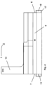
- Fig. 3 is a schematic side view of component 1 from the Fig. 1 and 2 shown.
- the first side 2 of the component 1 is provided with markings 15 to assist the installation personnel in creating openings in the first side 2.
- the markings 15 can, for example, be printed on the first side 2 or formed as recessed or raised sections in the injection molding process during the manufacture of the component 1.
- openings 16 are provided through the first side 2, for example to insert a saw or other cutting tool through there.
- the passages to be created in the first side 2 of the component 1 are required, for example, to connect pipes required for fluid transport.
- Connecting means 10, 11 are formed on the fifth side 6 and the sixth side 7.
- a third connecting means 10 is provided on the fifth side 6 and a fourth connecting means 11 is provided on the sixth side 7.
- the connecting means 10, 11 are each formed as alternately arranged projections and depressions on the fifth side 6 and sixth side 7.
- the projections and recesses forming the connecting means 10, 11 are dimensioned and positioned such that a projection can be inserted into a recess along each side 6, 7 in order to establish a connection state between two adjacent identical components 1, 1'.
- the second side 3 of the component 1 has locking openings 18 into which locking lugs 17, which are formed on the connecting means 10, 11 designed as projections, can snap into when a connection state is established between two adjacent identical components 1, 1', whereby a fixed connection state can be established.
- Fig. 4 is another schematic side view of component 1 from the Fig. 1 and 2 shown.
- the projection 14 of the component 1, which projects vertically from the second side 3, is arranged on the second side 3 at the end towards the sixth side 7.
- Fig. 5 is a schematic plan view of the component 1 from the Fig. 1 and 2
- the reference numerals in the Fig. 5 correspond to those of the previous figures.
- FIG. 5 a plan view of the first connecting means 8 on the third side 4 and the second connecting means 9 on the fourth side 5 is shown.
- the connecting means 8 and 9 are designed congruently to one another in order to establish a connection state between two adjacent identical components 1, 1'.
- Fig. 6 is a detail A from the Fig. 5 shown.
- a rear gripping section 13 is formed, which comprises a blunt nose and a recess in the form of such a blunt nose.
- a rear gripping section 12 is formed on the second connecting means 9 on the fourth side 5 of the component 1, which comprises an arrow-shaped tip and a recess in the form of such an arrow-shaped tip.
- Fig. 7 is a detail B from the Fig. 5 shown.
- first connecting means 8 on the third side 4 of the component 1 is shown in detail.
- a rear gripping section 12 is formed, which comprises an arrowed tip and a recess in the form of such an arrowed tip.
- a rear gripping section 13 is formed on the first connecting means 8 on the third side 4 of the component 1, which comprises a blunt nose and a recess in the form of such a blunt nose.
- the second connecting means 9 on the fourth side 5 of the component 1, which is in the Fig. 6 shown in detail, can be easily determined by rotating around the axis C according to Fig. 6 by 90 ° clockwise into the first connecting means 8 on the third side 4 of the component 1, which is in the Fig. 7 shown in detail.
- the C axis is oriented perpendicular to the plane of the drawing.
- Fig. 8 is a schematic plan view of a shaft element 102 made of four components 1, 1'.
- the shaft element 102 is made of four identical components, of which only the adjacent components 1, 1' will be discussed in more detail here, in that they are connected at their respective first connecting means 8 and second connecting means 9, in such a way that the second connecting means 9 of the first component 1 is connected to the first connecting means 8 of the adjacent, identical second component 1'.
- the first component 1 is then connected correspondingly with its first connecting means 8 to another component via its second connecting means 9, and so on.
- the second component 1' is further connected correspondingly with its second connecting means 9 to an adjacent component via its first connecting means 8. It goes without saying that the other components 1 for the shaft element 102, which are identical to one another, are connected in a similar manner.
- the inventive design of the component 1 results in a plan view of a square arrangement of four components 1, 1' connected to each other at an angle of 90° to the shaft element 102.
- the four projections 14 of the four Components 1 lie in one plane and define the opening 19 of the shaft element 102.
- Fig. 9 is a detail A from the Fig. 8 shown.
- connection of the first component 1 with the second component 1' is shown as an example in the detailed view of the Fig. 9 such that the second connecting means 9 of the first component 1 is inserted into the first connecting means 8 of the adjacent, identical second component 1' perpendicular to the plane of the drawing, or that the first connecting means 8 of the adjacent, identical second component 1' is inserted into the second connecting means 9 of the first component 1 perpendicular to the plane of the drawing.
- a projection 14 protrudes vertically from the second side 3 of each component 1, 1' of the shaft element 102. Since the projection 14 of the component 1 has the contour of a circular ring, in particular the contour of a quarter-circle ring, in some sections, the four projections 14 complement each other such that an opening 19 is formed in the shaft element 102, which opening is bordered by four projections 14.
Landscapes
- Engineering & Computer Science (AREA)
- Life Sciences & Earth Sciences (AREA)
- Civil Engineering (AREA)
- General Life Sciences & Earth Sciences (AREA)
- Mining & Mineral Resources (AREA)
- Paleontology (AREA)
- Environmental & Geological Engineering (AREA)
- General Engineering & Computer Science (AREA)
- Structural Engineering (AREA)
- Health & Medical Sciences (AREA)
- Hydrology & Water Resources (AREA)
- Public Health (AREA)
- Water Supply & Treatment (AREA)
Applications Claiming Priority (1)
| Application Number | Priority Date | Filing Date | Title |
|---|---|---|---|
| DE202019103687.7U DE202019103687U1 (de) | 2019-07-04 | 2019-07-04 | Bauelement und damit hergestelltes Schachtelement und Schacht |
Publications (3)
| Publication Number | Publication Date |
|---|---|
| EP3760802A1 EP3760802A1 (de) | 2021-01-06 |
| EP3760802C0 EP3760802C0 (de) | 2025-04-09 |
| EP3760802B1 true EP3760802B1 (de) | 2025-04-09 |
Family
ID=71111217
Family Applications (1)
| Application Number | Title | Priority Date | Filing Date |
|---|---|---|---|
| EP20180879.7A Active EP3760802B1 (de) | 2019-07-04 | 2020-06-18 | Bauelement und schacht bestehend aus den bauelementen |
Country Status (4)
| Country | Link |
|---|---|
| EP (1) | EP3760802B1 (pl) |
| DE (1) | DE202019103687U1 (pl) |
| HU (1) | HUE071529T2 (pl) |
| PL (1) | PL3760802T3 (pl) |
Families Citing this family (1)
| Publication number | Priority date | Publication date | Assignee | Title |
|---|---|---|---|---|
| BR202023011261Y1 (pt) * | 2023-06-07 | 2024-02-06 | Bruno Abramo Frederico | Disposição aplicada em caixa de passagem modular desmontável com encaixes por contrapressão |
Citations (1)
| Publication number | Priority date | Publication date | Assignee | Title |
|---|---|---|---|---|
| US20180313065A1 (en) * | 2015-10-29 | 2018-11-01 | Totetu Mfg. Co. Ltd. | Storage tank and method for constructing same |
Family Cites Families (10)
| Publication number | Priority date | Publication date | Assignee | Title |
|---|---|---|---|---|
| IT8400517U1 (it) * | 1984-02-10 | 1985-08-10 | Riccini S R L | Pozzetto componibile, realizzato in PVC o in altri materiali polimerici |
| DE10055327C1 (de) * | 2000-11-08 | 2002-01-24 | Sendenhorst Kunststoffroehren | Gitterplatte mit unterschiedlichen Strebenabständen |
| EP1607534A1 (en) * | 2004-06-18 | 2005-12-21 | Wavin B.V. | Infiltration block |
| DE202004018370U1 (de) * | 2004-11-26 | 2005-01-27 | Optigrün international AG | Kontrollschacht für ein Wasserleitsystem |
| US20070227094A1 (en) * | 2006-03-14 | 2007-10-04 | Larach Oscar | Modular raintank |
| US20100021236A1 (en) * | 2008-07-17 | 2010-01-28 | Kreikemeier John E | Water Retention/Detention Structure |
| DE102009004915A1 (de) * | 2009-01-16 | 2010-07-22 | Rehau Ag + Co. | Rigolensystem mit wenigstens einer Versickerbox |
| US8123436B2 (en) * | 2009-08-21 | 2012-02-28 | Oscar Larach | Underground infiltration tank module |
| US20130152499A1 (en) * | 2011-12-19 | 2013-06-20 | John E. Kriekemeier | Water retention/detention structure formed from identical panels |
| EP2940221A1 (de) * | 2014-05-02 | 2015-11-04 | Otto Graf GmbH Kunststofferzeugnisse | Kunststoff-Schacht |
-
2019
- 2019-07-04 DE DE202019103687.7U patent/DE202019103687U1/de active Active
-
2020
- 2020-06-18 HU HUE20180879A patent/HUE071529T2/hu unknown
- 2020-06-18 PL PL20180879.7T patent/PL3760802T3/pl unknown
- 2020-06-18 EP EP20180879.7A patent/EP3760802B1/de active Active
Patent Citations (1)
| Publication number | Priority date | Publication date | Assignee | Title |
|---|---|---|---|---|
| US20180313065A1 (en) * | 2015-10-29 | 2018-11-01 | Totetu Mfg. Co. Ltd. | Storage tank and method for constructing same |
Also Published As
| Publication number | Publication date |
|---|---|
| DE202019103687U1 (de) | 2020-10-06 |
| PL3760802T3 (pl) | 2025-07-28 |
| EP3760802A1 (de) | 2021-01-06 |
| EP3760802C0 (de) | 2025-04-09 |
| HUE071529T2 (hu) | 2025-09-28 |
Similar Documents
| Publication | Publication Date | Title |
|---|---|---|
| EP1917407A1 (de) | Lösbar aneinander zu befestigende, flächige bauteile, insbesondere bodenbelagsteile, sowie bauteil | |
| EP3555382B1 (de) | Rigolenhalbelement | |
| DE102009019492A1 (de) | Verriegelungssystem für Paneele | |
| EP3760802B1 (de) | Bauelement und schacht bestehend aus den bauelementen | |
| EP3760803B1 (de) | Schacht aus schachtelementen, die aus bauelementen hergestellt sind | |
| EP3555383B1 (de) | Rigolenhalbelement | |
| DE202017106688U1 (de) | Schachtbauteil oder Schacht | |
| DE102019007936A1 (de) | Bondingelement und bondingelement-herstellungsverfahren | |
| DE7636494U1 (de) | Kabelkasten | |
| EP3670755A1 (de) | Schalungsring für einen hybrid-ausgleichsring, hybrid-ausgleichsring und schachtbauwerk | |
| EP3832188B1 (de) | Anschlusssystem mit einem ansatzelement | |
| EP4272930A1 (de) | Schachtbauteil oder schacht | |
| DE202018100554U1 (de) | Adapterbauteil | |
| DE202017105796U1 (de) | Anschlussvorrichtung | |
| DE1805769A1 (de) | Baustein | |
| EP3441661B1 (de) | Anschlussvorrichtung | |
| DE202022107143U1 (de) | Bodengitteranordnung | |
| EP3441662B1 (de) | Anschlussstutzen | |
| DE102022111199A1 (de) | Schachtbauteil oder Schacht | |
| DE202022100633U1 (de) | Verbindungsstruktur | |
| DE102021130624A1 (de) | Abdichtungssystem | |
| DE202022107153U1 (de) | Rigolenanordnung | |
| EP3670754A1 (de) | Schalungsring für einen hybrid-auflagering, hybrid-auflagering und schachtbauwerk | |
| DE202018104583U1 (de) | Halteelement | |
| DE7736899U1 (de) | Zweiteilige Form zum Herstellen von Betonblöcken |
Legal Events
| Date | Code | Title | Description |
|---|---|---|---|
| PUAI | Public reference made under article 153(3) epc to a published international application that has entered the european phase |
Free format text: ORIGINAL CODE: 0009012 |
|
| STAA | Information on the status of an ep patent application or granted ep patent |
Free format text: STATUS: THE APPLICATION HAS BEEN PUBLISHED |
|
| AK | Designated contracting states |
Kind code of ref document: A1 Designated state(s): AL AT BE BG CH CY CZ DE DK EE ES FI FR GB GR HR HU IE IS IT LI LT LU LV MC MK MT NL NO PL PT RO RS SE SI SK SM TR |
|
| AX | Request for extension of the european patent |
Extension state: BA ME |
|
| STAA | Information on the status of an ep patent application or granted ep patent |
Free format text: STATUS: REQUEST FOR EXAMINATION WAS MADE |
|
| 17P | Request for examination filed |
Effective date: 20210702 |
|
| RBV | Designated contracting states (corrected) |
Designated state(s): AL AT BE BG CH CY CZ DE DK EE ES FI FR GB GR HR HU IE IS IT LI LT LU LV MC MK MT NL NO PL PT RO RS SE SI SK SM TR |
|
| RAP1 | Party data changed (applicant data changed or rights of an application transferred) |
Owner name: REHAU INDUSTRIES SE & CO. KG |
|
| RAP3 | Party data changed (applicant data changed or rights of an application transferred) |
Owner name: REHAU INDUSTRIES SE & CO. KG |
|
| STAA | Information on the status of an ep patent application or granted ep patent |
Free format text: STATUS: EXAMINATION IS IN PROGRESS |
|
| 17Q | First examination report despatched |
Effective date: 20221028 |
|
| GRAP | Despatch of communication of intention to grant a patent |
Free format text: ORIGINAL CODE: EPIDOSNIGR1 |
|
| STAA | Information on the status of an ep patent application or granted ep patent |
Free format text: STATUS: GRANT OF PATENT IS INTENDED |
|
| GRAS | Grant fee paid |
Free format text: ORIGINAL CODE: EPIDOSNIGR3 |
|
| GRAA | (expected) grant |
Free format text: ORIGINAL CODE: 0009210 |
|
| STAA | Information on the status of an ep patent application or granted ep patent |
Free format text: STATUS: THE PATENT HAS BEEN GRANTED |
|
| INTG | Intention to grant announced |
Effective date: 20250206 |
|
| AK | Designated contracting states |
Kind code of ref document: B1 Designated state(s): AL AT BE BG CH CY CZ DE DK EE ES FI FR GB GR HR HU IE IS IT LI LT LU LV MC MK MT NL NO PL PT RO RS SE SI SK SM TR |
|
| REG | Reference to a national code |
Ref country code: GB Ref legal event code: FG4D Free format text: NOT ENGLISH |
|
| REG | Reference to a national code |
Ref country code: CH Ref legal event code: EP |
|
| REG | Reference to a national code |
Ref country code: DE Ref legal event code: R096 Ref document number: 502020010781 Country of ref document: DE |
|
| REG | Reference to a national code |
Ref country code: IE Ref legal event code: FG4D Free format text: LANGUAGE OF EP DOCUMENT: GERMAN |
|
| U01 | Request for unitary effect filed |
Effective date: 20250507 |
|
| U07 | Unitary effect registered |
Designated state(s): AT BE BG DE DK EE FI FR IT LT LU LV MT NL PT RO SE SI Effective date: 20250513 |
|
| PGFP | Annual fee paid to national office [announced via postgrant information from national office to epo] |
Ref country code: GB Payment date: 20250605 Year of fee payment: 6 |
|
| PGFP | Annual fee paid to national office [announced via postgrant information from national office to epo] |
Ref country code: NO Payment date: 20250611 Year of fee payment: 6 |
|
| PGFP | Annual fee paid to national office [announced via postgrant information from national office to epo] |
Ref country code: HU Payment date: 20250605 Year of fee payment: 6 |
|
| U20 | Renewal fee for the european patent with unitary effect paid |
Year of fee payment: 6 Effective date: 20250614 |
|
| REG | Reference to a national code |
Ref country code: SK Ref legal event code: T3 Ref document number: E 46706 Country of ref document: SK |
|
| REG | Reference to a national code |
Ref country code: HU Ref legal event code: AG4A Ref document number: E071529 Country of ref document: HU |
|
| PG25 | Lapsed in a contracting state [announced via postgrant information from national office to epo] |
Ref country code: ES Free format text: LAPSE BECAUSE OF FAILURE TO SUBMIT A TRANSLATION OF THE DESCRIPTION OR TO PAY THE FEE WITHIN THE PRESCRIBED TIME-LIMIT Effective date: 20250409 |
|
| PG25 | Lapsed in a contracting state [announced via postgrant information from national office to epo] |
Ref country code: GR Free format text: LAPSE BECAUSE OF FAILURE TO SUBMIT A TRANSLATION OF THE DESCRIPTION OR TO PAY THE FEE WITHIN THE PRESCRIBED TIME-LIMIT Effective date: 20250710 |
|
| PGFP | Annual fee paid to national office [announced via postgrant information from national office to epo] |
Ref country code: PL Payment date: 20250617 Year of fee payment: 6 |
|
| PG25 | Lapsed in a contracting state [announced via postgrant information from national office to epo] |
Ref country code: HR Free format text: LAPSE BECAUSE OF FAILURE TO SUBMIT A TRANSLATION OF THE DESCRIPTION OR TO PAY THE FEE WITHIN THE PRESCRIBED TIME-LIMIT Effective date: 20250409 |
|
| PGFP | Annual fee paid to national office [announced via postgrant information from national office to epo] |
Ref country code: CH Payment date: 20250701 Year of fee payment: 6 |
|
| PG25 | Lapsed in a contracting state [announced via postgrant information from national office to epo] |
Ref country code: RS Free format text: LAPSE BECAUSE OF FAILURE TO SUBMIT A TRANSLATION OF THE DESCRIPTION OR TO PAY THE FEE WITHIN THE PRESCRIBED TIME-LIMIT Effective date: 20250709 |
|
| PGFP | Annual fee paid to national office [announced via postgrant information from national office to epo] |
Ref country code: CZ Payment date: 20250512 Year of fee payment: 6 |
|
| PGFP | Annual fee paid to national office [announced via postgrant information from national office to epo] |
Ref country code: SK Payment date: 20250512 Year of fee payment: 6 |
|
| PG25 | Lapsed in a contracting state [announced via postgrant information from national office to epo] |
Ref country code: IS Free format text: LAPSE BECAUSE OF FAILURE TO SUBMIT A TRANSLATION OF THE DESCRIPTION OR TO PAY THE FEE WITHIN THE PRESCRIBED TIME-LIMIT Effective date: 20250809 |
|
| PG25 | Lapsed in a contracting state [announced via postgrant information from national office to epo] |
Ref country code: SM Free format text: LAPSE BECAUSE OF FAILURE TO SUBMIT A TRANSLATION OF THE DESCRIPTION OR TO PAY THE FEE WITHIN THE PRESCRIBED TIME-LIMIT Effective date: 20250409 |
|
| PG25 | Lapsed in a contracting state [announced via postgrant information from national office to epo] |
Ref country code: MC Free format text: LAPSE BECAUSE OF FAILURE TO SUBMIT A TRANSLATION OF THE DESCRIPTION OR TO PAY THE FEE WITHIN THE PRESCRIBED TIME-LIMIT Effective date: 20250409 |
|
| PLBE | No opposition filed within time limit |
Free format text: ORIGINAL CODE: 0009261 |
|
| STAA | Information on the status of an ep patent application or granted ep patent |
Free format text: STATUS: NO OPPOSITION FILED WITHIN TIME LIMIT |