EP3758939B1 - Trockner - Google Patents
Trockner Download PDFInfo
- Publication number
- EP3758939B1 EP3758939B1 EP19709838.7A EP19709838A EP3758939B1 EP 3758939 B1 EP3758939 B1 EP 3758939B1 EP 19709838 A EP19709838 A EP 19709838A EP 3758939 B1 EP3758939 B1 EP 3758939B1
- Authority
- EP
- European Patent Office
- Prior art keywords
- printing
- openings
- nozzle body
- gas
- dryer
- Prior art date
- Legal status (The legal status is an assumption and is not a legal conclusion. Google has not performed a legal analysis and makes no representation as to the accuracy of the status listed.)
- Active
Links
Images



Classifications
-
- B—PERFORMING OPERATIONS; TRANSPORTING
- B41—PRINTING; LINING MACHINES; TYPEWRITERS; STAMPS
- B41F—PRINTING MACHINES OR PRESSES
- B41F23/00—Devices for treating the surfaces of sheets, webs, or other articles in connection with printing
- B41F23/04—Devices for treating the surfaces of sheets, webs, or other articles in connection with printing by heat drying, by cooling, by applying powders
- B41F23/0403—Drying webs
- B41F23/0423—Drying webs by convection
- B41F23/0426—Drying webs by convection using heated air
-
- B—PERFORMING OPERATIONS; TRANSPORTING
- B41—PRINTING; LINING MACHINES; TYPEWRITERS; STAMPS
- B41F—PRINTING MACHINES OR PRESSES
- B41F23/00—Devices for treating the surfaces of sheets, webs, or other articles in connection with printing
- B41F23/04—Devices for treating the surfaces of sheets, webs, or other articles in connection with printing by heat drying, by cooling, by applying powders
- B41F23/0403—Drying webs
- B41F23/0423—Drying webs by convection
- B41F23/043—Drying webs by convection using gas or fuel burners
-
- F—MECHANICAL ENGINEERING; LIGHTING; HEATING; WEAPONS; BLASTING
- F26—DRYING
- F26B—DRYING SOLID MATERIALS OR OBJECTS BY REMOVING LIQUID THEREFROM
- F26B13/00—Machines and apparatus for drying fabrics, fibres, yarns, or other materials in long lengths, with progressive movement
- F26B13/10—Arrangements for feeding, heating or supporting materials; Controlling movement, tension or position of materials
- F26B13/108—Arrangements for feeding, heating or supporting materials; Controlling movement, tension or position of materials using one or more blowing devices, e.g. nozzle bar, the effective area of which is adjustable to the width of the material
-
- F—MECHANICAL ENGINEERING; LIGHTING; HEATING; WEAPONS; BLASTING
- F26—DRYING
- F26B—DRYING SOLID MATERIALS OR OBJECTS BY REMOVING LIQUID THEREFROM
- F26B21/00—Arrangements for supplying or controlling air or other gases for drying solid materials or objects
- F26B21/20—Circulating air or gases in closed cycles, e.g. wholly within the drying enclosure
-
- F—MECHANICAL ENGINEERING; LIGHTING; HEATING; WEAPONS; BLASTING
- F26—DRYING
- F26B—DRYING SOLID MATERIALS OR OBJECTS BY REMOVING LIQUID THEREFROM
- F26B21/00—Arrangements for supplying or controlling air or other gases for drying solid materials or objects
- F26B21/50—Ducting arrangements from the source of air or other gases to the materials or objects being dried
-
- F—MECHANICAL ENGINEERING; LIGHTING; HEATING; WEAPONS; BLASTING
- F26—DRYING
- F26B—DRYING SOLID MATERIALS OR OBJECTS BY REMOVING LIQUID THEREFROM
- F26B21/00—Arrangements for supplying or controlling air or other gases for drying solid materials or objects
- F26B21/50—Ducting arrangements from the source of air or other gases to the materials or objects being dried
- F26B21/55—Outlets for directing or distributing the air or other gases
Definitions
- the invention relates to a dryer for gassing a running printing web in a rotary printing machine, with a nozzle body.
- Rotary printing machines are essentially printing machines in which printing webs or material webs on spools are unrolled and printed and then rolled up again.
- the printing machines are designed for different materials, such as paper or film.
- different inks are used, such as solvent, water or indicator inks.
- drying nozzles are used to dry the ink of the images printed on the printing web.
- a drying gas is introduced into a nozzle body whose nozzle slot is directed towards the printing web so that the printing web is gassed as evenly as possible with the drying gas across its entire width and is thus dried.
- a drying nozzle with a hollow nozzle body whereby the nozzle body has a nozzle slot extending transversely to the direction of travel of the printing material web.
- the nozzle body has an inner tube and an outer tube enclosing the inner tube, each of which has at least one outlet opening in its peripheral wall, and that the nozzle slot is formed by an overlap zone of the outlet openings of the inner tube and the outer tube and is adjustable by changing the angular position of the inner tube relative to the outer tube.
- the EP 0 103 876 A2 discloses a ventilation device for a printing machine, in particular for a rotary gravure printing machine, wherein the ventilation device has a ventilation hood in which several ventilation sections are provided. Suction holes are provided between the ventilation sections.
- the object of the invention is to provide a dryer which is able to operate with lower gas velocities/pressures and thus lower performances.
- a dryer for gassing a moving printing web in a rotary printing machine, with a nozzle body which has a plurality of openings for the exit of heated gas which extend only over a part of a width of the printing web and protrude from a nozzle base body of the nozzle body and are designed as nozzles, and the dryer has a plurality of openings for sucking in the cooled gas which are arranged at least partially between the openings for the exit of heated gas, wherein the nozzle body has a cavity through which the heated gas is supplied to the printing web and the openings for sucking in the cooled gas are provided outside the cavity, wherein a grid plate is arranged on the nozzle base body, in which the openings for sucking in the cooled gas are provided.
- Good results were achieved when at least one opening had a round, oval or a shape that approximated such a shape.
- the openings can all have the same or different shapes. Good results were achieved, for example, with openings that had an outlet opening in the range of 1 to 10 mm, preferably 2 to 5 mm.
- the dryer is designed such that the nozzle body has a cavity through which the heated gas is supplied to the printing web.
- a connection for supplying the heated gas can be provided on the nozzle body, through which the heated gas is supplied into the cavity.
- the at least one opening for the exit of heated gas protrudes from a peripheral surface of the nozzle body. This ensures that the heated gas is fed directly to the printing web.
- an opening for returning the cooled gas is provided outside the cavity. This makes it possible, for example, to draw off the cooled gas along the nozzle body and to the side.
- the nozzle body In order to achieve particularly good drying results, it can be advantageous for the nozzle body to be essentially at least the width of the printing web.
- the invention relates to a Rotary printing machine comprising a printing cylinder for printing on a moving printing web and the above-described dryer for gassing the printing web, so that a negative pressure is present at least substantially in the region between the outlet of the heated gas and the printing web.
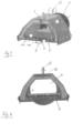
- Fig. 1 is a perspective view of a nozzle body 1 according to a preferred embodiment of the invention, the structure of which is shown below as an intermediate drying nozzle by way of example.
- the dryer consists of a so-called overpressure and a negative pressure area.
- the heated gas required for drying flows out of openings 2, which protrude from the nozzle body 5 and are designed as nozzles, here small "holes", hits the freshly printed material web or printing web and is sucked in again through other openings 3 provided. In this way, it can be avoided that the air-solvent mixture gets into the atmosphere.
- the openings are well in Fig. 2 , a detailed view.
- Fig. 1 shows the area from which the air flows out and is simultaneously sucked in again. From the zoom view of Fig. 2 the structure of the drying nozzle becomes visible.
- a type of sheet metal 4 is provided on the nozzle body, which is designed here as a grid sheet, which is fastened to the milled base body 5, for example, by means of rivets.
- This base body 5 is in turn fastened in a main frame, for example by means of screws.
- Fig. 7 shows a nozzle body in a view of the outlet nozzles.
- the nozzles are the openings 2, which have a substantially round shape and are all essentially the same.
- the openings are arranged transversely in the direction of travel of the printing web in a kind of line, while they are arranged offset at an angle in the direction of travel of the printing web.
- the angle can be in a range of 2 to 30°, preferably 5 to 15°.
- FIG. 3 an exemplary structure of a nozzle body 1 is shown in a perspective view.
- Fig. 4 shows a cross section of this nozzle body.
- the air which is either already heated or is still being heated, enters the cavity 7 of the nozzle body or overpressure area through a nozzle 6.
- the air leaves this through the small outlet openings 2 (arrow 8), hits the material of the tape to be printed on, turns around (arrow 10) and passes through the recesses in the milled base body (arrows 9 and 10) to the side ends 11.
- the medium flows "above” the overpressure area or past the overpressure area in the direction of the suction opening 12.
- stud bolts 13 Above this suction opening there are preferably so-called stud bolts 13 to which the air suction is connected.
- the air suction consists of differently screwed nozzles depending on the width of the nozzle.
- a flexible, solvent-resistant and heat-resistant hose is connected to this nozzle, which transports the solvent-laden air to a collecting pipe.
- Fig. 5 is detailed view of the nozzle body 1 after Fig. 1 shown here is the inlet or nozzle for the heated or to be heated air or gas.
- Fig. 6 shows a dryer according to another preferred embodiment in an installed state.
- the entire drying unit is arranged here, for example, between a crossbeam 14 and a central cylinder 15 in a rotary printing machine.
- Two dryers can be seen, although more dryers can also be arranged.
- the nozzle body 1 is attached to a printing unit by means of a holder 16.
- a collecting pipe 17, into which the exhaust air is discharged, is located on sheet metal holders 18, which are suspended in the cross-member 14, according to the embodiment shown.
- a dryer according to the present invention it is now also possible, thanks to its modular design, to install and remove it from the printing unit for cleaning purposes without dismantling other components. With appropriate connections, the modular design also allows individual components to be installed without tools.
Landscapes
- Engineering & Computer Science (AREA)
- Mechanical Engineering (AREA)
- General Engineering & Computer Science (AREA)
- Textile Engineering (AREA)
- Drying Of Solid Materials (AREA)
- Supply, Installation And Extraction Of Printed Sheets Or Plates (AREA)
Description
- Die Erfindung betrifft einen Trockner zum Begasen einer laufenden Bedruckbahn in einer Rotationsdruckmaschine, mit einem Düsenkörper.
- Rotationsdruckmaschinen sind im wesentlichen Druckmaschinen, bei denen sich auf Spulen befindende Bedruckbahnen bzw. Materialbahnen abgerollt und bedruckt und danach wieder aufgerollt werden. Die Druckmaschinen sind für unterschiedliche Materialien, wie z.B. Papier oder Folie konzipiert. Des Weiteren kommen unterschiedliche Farben, wie Lösemittel-, Wasser oder Indikator- Farben zum Einsatz.
- In Rotationsdruckmaschinen werden Trocknungsdüsen dazu eingesetzt, die Druckfarbe der auf die Bedruckbahn aufgedruckten Bilder zu trocknen. Dazu wird ein Trocknungsgas in einen Düsenkörper eingeleitet, dessen Düsenschlitz auf die Bedruckbahn gerichtet ist, so dass die Bedruckbahn auf ganzer Breite möglichst gleichmäßig mit dem Trocknungsgas begast und dadurch getrocknet wird.
- Weiterhin ist es bekannt, einen Blech-Korpus, der in zwei Kammern aufgeteilt ist, zu als Trockner zu verwenden. Die eine Kammer (Zuluft-Kammer) leitet, das erwärmte Gas zu der trocknenden Materialbahn, die andere Kammer (AbluftKammer) führt die mit Lösemittel oder Wasser angereicherte Luft von der Materialbahn. In der Zuluft-Kammer befindet sich eine so genannte Düsenlanze, die zur Reinigung aus der Kammer entnommen werden kann. Diese Lanze besteht aus einem 5 mm breiten Schlitz, aus dem das Gas zur Materialbahn strömt. Damit eine bessere Luftführung erreicht wird, sind zusätzlich zur keilförmigen Form kleine Leitbleche eingebarbeitet.
- Aus der
DE 20 2016 102 780 ist beispielsweise eine Trocknungsdüse mit einem hohlen Düsenkörper bekannt, wobei der Düsenkörper einen sich quer zur Laufrichtung der Bedruckstoffbahn erstreckenden Düsenschlitz aufweist. Damit sich die Trocknungsdüse einfach an unterschiedliche Einsatzfälle anpassen lässt, weist der Düsenkörper ein Innenrohr und ein das Innenrohr umschließendes Außenrohr auf, die jeweils in ihrer Umfangswand mindestens eine Austrittsöffnung aufweisen, und dass der Düsenschlitz durch eine Überlappungszone der Austrittsöffnungen des Innenrohres und des Außenrohres gebildet wird und durch Ändern der Winkelstellung des Innenrohres relativ zum Außenrohr verstellbar ist. - Aus der
EP 3 112 156 A1 ist es eine Anordnung mehrerer sich über die gesamte Breite der Bedruckbahn erstreckende Düsen hintereinander bekannt. Diese Anordnung ist sehr gross und eignet sich daher nur für den Einsatz als Nachtrocknungsanordnung. - Bei den aus dem Stand der Technik bekannten Trocknern hat es sich weiterhin als nachteilig erwiesen, dass durch die Ungleichmäßigkeit der Luftströmung zu einem ungleichmäßigen Trocknungsergebnis führt. Das bedeutet, bezogen auf die Breite der Materialbahn, die Farbe einen unterschiedlichen "Trocknungs- Stand" aufweist. Hinzu kommt, dass die Materialbahn bei rechnerisch benötigter Trocknungs-Leistung auf dem Zylinder hin und her wandert, wodurch beim Druckprozess Passa- Schwankungen / Register- Schwankungen entstehen, welches die Druckqualität maßgeblich mindert. Die Folge ist, dass die benötigte Trocknungsleistung nicht eingestellt werden dann und dadurch nicht die tatsächlich mögliche Leistung der Trocknung nicht erreicht wird.
- Die
EP 0 103 876 A2 offenbart eine Belüftungsvorrichtung für eine Druckmaschine, insbesondere für eine Tiefdruckrotationsmaschine, wobei die Belüftungsvorrichtung eine Belüftungshaube aufweist, in der mehrere Belüftungsabschnitte vorgesehen sind. Zwischen den Belüftungsabschnitten sind Absaugbohrungen vorgesehen. - Aufgabe der Erfindung ist es, einen Trockner bereitzustellen, der in der Lage ist mit geringeren Gasgeschwindigkeiten /-drücken und damit geringeren Leistungen zu arbeiten.
- Diese Aufgabe wird erfindungsgemäß durch einen Trockner gemäß Anspruch 1 gelöst, nämlich einen Trockner zum Begasen einer sich bewegenden Bedruckbahn in einer Rotationsdruckmaschine, mit einem Düsenkörper, der mehrere sich nur über einen Teil einer Breite der Bedruckbahn erstreckende und von einem Düsengrundkörper des Düsenkörpers hervorstehende und als Düsen ausgebildete Öffnungen zum Austritt von erwärmtem Gas aufweist und der Trockner mehrere zumindest teilweise zwischen den Öffnungen zum Austritt von erwärmtem Gas angeordnete Öffnungen zum Ansaugen des abgekühlten Gases aufweist, wobei der Düsenkörper einen Hohlraum aufweist, durch den das erwärmte Gas der Bedruckbahn zugeführt wird und die Öffnungen zum Ansaugen des abgekühlten Gases ausserhalb des Hohlraums vorgesehen sind, wobei auf dem Düsengrundkörper ein Gitterblech angeordnet ist, in dem die Öffnungen zum Ansaugen des abgekühlten Gases vorgesehen sind.
- Mit einem Trockner nach der vorliegenden Erfindung konnten nun in einfacher Art und Weise bessere Trocknereigenschaften erzielt werden, die im Wesentlichen unabhängig sind von dem zu bedruckenden Material.
- So kann vorteilhafterweise bei relativ geringem Platzaufwand über die gesamte Bedruckbahn eine gleichmäßige Luftströmung erreicht werden, was zu einem gleichmäßigen Trocknungsergebnis führt. Durch die homogene Luftführung treten deutlich geringere Verwirbelungen auf, die die Materialbahn nicht beeinflussen. Durch diese Eigenschaft erhöht der Trockner die Druckqualität enorm. Im Vergleich zum herkömmlichen Trocknern ist es nun darüber hinaus möglich diesen ohne Demontage von weiteren Komponenten zu Reinigungszwecken ein- und auszubauen. Durch den modularen Aufbau lassen sich einzelne Komponenten entnehmen und dies unter Umständen sogar werkzeuglos.
- Vorteilhafte Weiterbildungen der vorliegenden Erfindung sind Gegenstand der abhängigen Ansprüche.
- Als besonders vorteilhaft hat es sich erwiesen, wenn die Öffnungen zum Austritt von erwärmten Gas zumindest teilweise versetzt angeordnet sind. Dadurch wird es möglich, dass jeder Bereich der Bedruckbahn auch getrocknet wird.
- Gute Ergebnisse konnten erzielt werden, wenn die zumindest eine Öffnung eine runde, ovale, oder eine an eine solche Form angenäherte Form aufweist. Dabei können die Öffnungen alle die gleiche oder unterschiedliche Formen aufweisen. Gute Ergebnisse wurden beispielsweise mit Öffnungen erzielt, die eine Austrittsöffnung im Bereich von 1 bis 10 mm, vorzugsweise 2 bis 5 mm aufweisen.
- Gemäss einer bevorzugten Ausführungsform der Erfindung ist der Trockner derart ausgestaltet, dass der Düsenkörper einen Hohlraum aufweist, durch den das erwärmte Gas der Bedruckbahn zugeführt wird. Derart kann beispielsweise ein Anschluss zum Zuführen des erwärmten Gases an dem Düsenkörper vorgesehen sein, durch den das erwärmte Gas in den Hohlraum zugeführt wird.
- Es hat sich als vorteilhaft erwiesen, wenn die zumindest eine Öffnung zum Austritt von erwärmtem Gas einer Umfangsfläche des Düsenkörpers hervorsteht. Derart kann sichergestellt werden, dass das erwärmte Gas direkt der Bedruckbahn zugeführt wird.
- Gemäss einer weiteren vorteilhaften Ausgestaltung der Erfindung ist die eine Öffnung zum Rückführen des abgekühlten Gases ausserhalb des Hohlraums vorgesehen. So ist es beispielsweise möglich, das abgekühlte Gas am Düsenkörper entlang und seitlich abzuziehen.
- Hierbei kann es vorteilhaft sein, dass zum Rückführen des abgekühlten Gases eine Absaugung vorgesehen ist.
- Gute Ergebnisse wurden erzielt, wenn als Gas Umgebungsluft verwendet wird. Um besonders gute Trockenergebnisse zu erreichen kann es vorteilhaft sein, dass der Düsenkörper im Wesentlichen zumindest die Breite der Bedruckbahn aufweist.
- Gemäss einem weiteren Aspekt betrifft die Erfindung eine Rotationsdruckmaschine umfassend einen Druckzylinder zum Bedrucken einer sich bewegenden Bedruckbahn und den oben beschriebenen Trockner zum Begasen der Bedruckbahn, so dass zumindest im Wesentlichen im Bereich zwischen dem Austritt des erwärmten Gases und der Bedruckbahn ein Unterdruck vorliegt.
- Im Folgenden werden Ausführungsbeispiele der Erfindung anhand der Zeichnung näher erläutert.
- Es zeigen:
- Fig. 1
- eine perspektivische Ansicht eines Düsenkörpers nach einer bevorzugten Ausführungsform der Erfindung;
- Fig. 2
- eine Detailansicht des Düsenkörpers gemäss einer bevorzugten Ausführungsform der Erfindung;
- Fig. 3
- eine perspektivische Schnittansicht des Düsenkörpers gemäss einer bevorzugten Ausführungsform der Erfindung;
- Fig. 4
- einen Querschnitt des Düsenkörpers nach
Fig. 3 ; - Fig. 5
- eine Detailansicht des Düsenkörpers nach
Fig. 1 ; und - Fig. 6
- einen Trockner nach einer weiteren bevorzugten Ausführungsform in einem eingebauten Zustand.
- Fig. 7
- Komplett montierter Düsenkörper in Draufsicht
- In
Fig. 1 ist eine perspektivische Ansicht eines Düsenkörpers 1 nach einer bevorzugten Ausführungsform der Erfindung dargestellt, wobei nachfolgend beispielhaft der Aufbau dieser als eine Zwischentrocknungsdüse dargestellt ist. Der Trockner besteht dabei gemäss der gezeigten Ausführungsform aus einem sogenannten Überdruck- und einem Unterdruckbereich. - Das zur Trocknung benötigte, erwärmte Gas, beispielsweise Luft, strömt aus Öffnungen 2, die dem Düsengrundkörper 5 hervorstehende und als Düsen ausgebildet sind, hier kleinen "Löchern" aus, trifft auf die frisch bedruckte Materialbahn bzw. Bedruckbahn und wird durch vorgesehene andere Öffnungen 3 wieder angesaugt. Derart kann es vermieden werden, dass Luft-LösemittelGemisch in die Atmosphäre gelangt. Die Öffnungen sind gut in
Fig. 2 , einer Detailansicht, zu erkennen.Fig. 1 zeigt den Bereich, aus dem die Luft ausströmt und gleichzeitig wieder eingesaugt wird. Aus der Zoom-Ansicht vonFig. 2 wird der Aufbau der Trocknungsdüse sichtbar. - Bei der dargestellten Ausführung ist auf dem Düsenkörper eine Art Blech 4 vorgesehen, das hier als Gitterblech ausgebildet ist, das beispielsweise mittels Nieten auf dem beispielsweise gefrästen Grundkörper 5 befestigt ist. Dieser Grundkörper 5 wird wiederum in einem Hauptrahmen beispielsweise mittels Schrauben befestigt.
- Im Bereich zwischen Trockner und Gegendruckzylinder liegt gemäss der dargestellten bevorzugten Ausführungsform ein gleichmäßig, permanenter Unterdruck vor, der einerseits verhindert, dass lösemittelbeladene Luft in die Umgebung strömt, andererseits wird die lösemittelbeladene Luft aus dem gesamten Druckwerk eingesaugt und abgeführt.
-
Fig. 7 zeigt einen Düsenkörper in einer Ansicht auf die Auslassdüsen. Hierbei sind die Düsen die Öffnungen 2, die eine im wesentlichen runde Form haben und alle im Wesentlichen gleich ausgebildet sind. Die Öffnungen sind dabei quer in Fortbewegungsrichtung der Bedruckbahn in einer Art Linie angeordnet, während sie in Fortbewegungsrichtung der Bedruckbahn mit einem Winkel versetzt angeordnet sind. Der Winkel kann dabei in einem Bereich von 2 bis 30°, vorzugsweise 5 bis 15° liegen. - In
Figur 3 ist ein beispielhafter Aufbau eines Düsenkörpers 1 in einer perspektivischen Ansicht dargestellt.Fig. 4 zeigt einen Querschnitt dieses Düsenkörpers. - Die Luft, die entweder schon erwärmt ist oder noch erwärmt wird gelangt durch einen Stutzen 6 in den Hohlraum 7 des Düsenkörpers, bzw. Überdruckbereich. Die Luft verlässt diesen durch die kleinen Austrittsöffnungen 2 (Pfeil 8), prallt gegen das Material des zu bedruckenden Bandes, kehrt um (Pfeil 10) und gelangt durch die Aussparungen im gefrästen Grundkörper (Pfeil 9 und10) zu den seitlichen Enden 11. Dort angekommen, strömt das Medium "oberhalb" des Überdruckbereichs oder am Überdruckbereich vorbei in Richtung Absaugöffnung 12. Oberhalb dieser Absaugöffnung befinden sich vorzugsweise sogenannte Stehbolzen 13 an denen die Luftabsaugung angeschlossen wird. Die Luftabsaugung besteht, je nach Breite der Düse, aus unterschiedlich angeschraubten Stutzen. An diesen Stutzen wird ein flexibler, lösemittelbeständiger und hitzebeständiger Schlauch angeschlossen, der die lösemittelbeladene Luft zu einem Sammelrohr transportiert.
- In
Fig. 5 ist Detailansicht des Düsenkörpers 1 nachFig. 1 dargestellt, hier ist der Einlass bzw. Stutzen für die erwärmte oder zu erwärmende Luft bzw. Gas dargestellt. -
Fig. 6 zeigt einen Trockner nach einer weiteren bevorzugten Ausführungsform in einem eingebauten Zustand. - Es ist zu erkennen, dass sich die gesamte Trocknungseinheit hier beispielsweise zwischen einer Quertraverse 14 und einem Zentralzylinder 15 in einer Rotationsdruckmaschine angeordnet ist. In
Fig. 6 sind dazu zwei Trockner zu sehen, wobei auch mehr Trockner angeordnet werden können. Der Düsenkörper 1 ist mittels Halter 16 in einem Druckwerk befestigt. Ein Sammelrohr 17, in das die Abluft abgeleitet wird, befindet sich gemäss der gezeigten Ausführungsform auf Blechhaltern 18, die in der Quertraverse 14 eingehängt werden. Durch die Verwendung von flexiblen Schläuchen zur Verbindung des Düsenkörpers 1 mit dem Sammelrohr 17 ist es beispielsweise möglich, den Düsenkörper etwas in Richtung Quertraverse bewegen/ziehen zu können, um Materialreste, die sich am Blech verhakt haben zu entnehmen. - Wie aus der
Fig. 6 gut ersichtlich ist, ist es mit einem Trockner nach der vorliegenden Erfindung nun darüber hinaus möglich, durch den modularen Aufbau, diesen ohne Demontage von weiteren Komponenten zu Reinigungszwecken aus dem Druckwerk ein- und auszubauen. Bei entsprechenden Anbindungen lassen sich durch den modularen Aufbau einzelne Komponenten auch werkzeuglos montieren.
Claims (5)
- Trockner zum Begasen einer sich bewegenden Bedruckbahn in einer Rotationsdruckmaschine, mit einem Düsenkörper (1), wobei der Düsenkörper (1) mehrere sich nur über einen Teil einer Breite der Bedruckbahn erstreckende und von einem Düsengrundkörper (5) des Düsenkörpers (1) hervorstehende und als Düsen ausgebildete Öffnungen (2) zum Austritt von erwärmtem Gas aufweist und der Trockner mehrere zumindest teilweise zwischen den Öffnungen (2) zum Austritt von erwärmtem Gas angeordnete Öffnungen (3) zum Ansaugen des abgekühlten Gases aufweist, wobei der Düsenkörper einen Hohlraum (7) aufweist, durch den das erwärmte Gas der Bedruckbahn zugeführt wird und die Öffnungen (3) zum Ansaugen des abgekühlten Gases ausserhalb des Hohlraums (7) vorgesehen sind, dadurch gekennzeichnet, dass auf dem Düsengrundkörper (5) ein Gitterblech (4) angeordnet ist, in dem die Öffnungen (3) zum Ansaugen des abgekühlten Gases vorgesehen sind.
- Trockner nach Anspruch 1, dadurch gekennzeichnet, dass die Öffnungen (2) zum Austritt von erwärmtem Gas zumindest teilweise versetzt angeordnet sind.
- Trockner nach einem der vorhergehenden Ansprüche, dadurch gekennzeichnet, dass zumindest eine Öffnung (2) eine runde, ovale, oder an eine solche Form angenäherte Form aufweist.
- Trockner nach einem der vorhergehenden Ansprüche, dadurch gekennzeichnet, dass zum Rückführen des abgekühlten Gases eine Absaugung vorgesehen ist.
- Rotationsdruckmaschine umfassend einen Druckzylinder zum Bedrucken einer sich bewegenden Bedruckbahn und einen Trockner zum Begasen der Bedruckbahn, nach einem der vorhergehenden Ansprüche, so dass zumindest im Wesentlichen im Bereich zwischen dem Austritt des erwärmten Gases und der Bedruckbahn ein Unterdruck vorliegt.
Applications Claiming Priority (2)
| Application Number | Priority Date | Filing Date | Title |
|---|---|---|---|
| EP18020082 | 2018-02-27 | ||
| PCT/EP2019/025053 WO2019166129A1 (de) | 2018-02-27 | 2019-02-26 | Trockner |
Publications (2)
| Publication Number | Publication Date |
|---|---|
| EP3758939A1 EP3758939A1 (de) | 2021-01-06 |
| EP3758939B1 true EP3758939B1 (de) | 2025-01-08 |
Family
ID=61622294
Family Applications (1)
| Application Number | Title | Priority Date | Filing Date |
|---|---|---|---|
| EP19709838.7A Active EP3758939B1 (de) | 2018-02-27 | 2019-02-26 | Trockner |
Country Status (5)
| Country | Link |
|---|---|
| US (1) | US11559980B2 (de) |
| EP (1) | EP3758939B1 (de) |
| CN (1) | CN112041168B (de) |
| ES (1) | ES3004342T3 (de) |
| WO (1) | WO2019166129A1 (de) |
Families Citing this family (2)
| Publication number | Priority date | Publication date | Assignee | Title |
|---|---|---|---|---|
| EP3932672B1 (de) * | 2020-07-01 | 2024-05-15 | Bobst Bielefeld GmbH | Druckmaschine mit einem trockner |
| EP4467346B1 (de) * | 2023-05-24 | 2025-12-03 | Canon Kabushiki Kaisha | Trocknungsvorrichtung |
Family Cites Families (15)
| Publication number | Priority date | Publication date | Assignee | Title |
|---|---|---|---|---|
| US3494048A (en) | 1968-01-22 | 1970-02-10 | Fmc Corp | Web edge baffle in jet drying hood |
| IT1153853B (it) * | 1982-09-22 | 1987-01-21 | Cerutti Spa Off Mec | Dispositivo di ventilazione per macchine da stampa, in particolare per macchine rotative a rotocalco |
| US6293196B1 (en) | 1993-10-06 | 2001-09-25 | Howard W. DeMoore | High velocity, hot air dryer and extractor |
| DE19915923C2 (de) * | 1999-04-09 | 2001-10-04 | Babcock Textilmasch | Umlufttrockner |
| CN2363255Y (zh) | 1999-02-11 | 2000-02-09 | 梁德才 | 节能高效干燥装置 |
| DE10125771C1 (de) * | 2001-05-26 | 2002-11-21 | Eisenmann Kg Maschbau | Trockner |
| US9068775B2 (en) * | 2009-02-09 | 2015-06-30 | Heat Technologies, Inc. | Ultrasonic drying system and method |
| ES2426113T3 (es) | 2009-07-24 | 2013-10-21 | Bobst Italia S.P.A. | Equipo de secado con tratamiento de aire falso para máquinas de impresión |
| DE102009059822B4 (de) * | 2009-12-21 | 2015-12-10 | Grenzebach Bsh Gmbh | Verfahren und Vorrichtung zum Trocknen von Gipsplatten |
| CN101830104B (zh) | 2010-05-28 | 2012-01-25 | 张雨晨 | 一种用于多色印刷印间烘炉的带有热风循环的排风系统 |
| DE102011110842A1 (de) | 2011-08-23 | 2013-02-28 | Outotec Oyj | Vorrichtung und Verfahren zur thermischen Behandlung von stückigem oder agglomeriertem Material |
| EP3112156B1 (de) | 2015-06-30 | 2018-05-02 | Maklaus S.r.l. | Flexodruckmaschine mit erhöhter funktionalität, insbesondere zum bedrucken von feinem und streckbarem material |
| CN105398205B (zh) | 2015-12-23 | 2017-12-12 | 青岛莱伊迪光电科技有限公司 | 一种led uv印刷固化装置 |
| CN105398206B (zh) | 2015-12-29 | 2018-01-19 | 重庆科欣塑料有限公司 | 一种烘干设备 |
| DE202016102780U1 (de) | 2016-05-25 | 2017-10-05 | Bobst Bielefeld Gmbh | Trocknungsdüse |
-
2019
- 2019-02-26 ES ES19709838T patent/ES3004342T3/es active Active
- 2019-02-26 CN CN201980028761.9A patent/CN112041168B/zh active Active
- 2019-02-26 WO PCT/EP2019/025053 patent/WO2019166129A1/de not_active Ceased
- 2019-02-26 EP EP19709838.7A patent/EP3758939B1/de active Active
- 2019-02-26 US US16/976,051 patent/US11559980B2/en active Active
Also Published As
| Publication number | Publication date |
|---|---|
| CN112041168A (zh) | 2020-12-04 |
| US11559980B2 (en) | 2023-01-24 |
| EP3758939A1 (de) | 2021-01-06 |
| US20210001620A1 (en) | 2021-01-07 |
| CN112041168B (zh) | 2022-04-12 |
| WO2019166129A1 (de) | 2019-09-06 |
| ES3004342T3 (en) | 2025-03-12 |
Similar Documents
| Publication | Publication Date | Title |
|---|---|---|
| DE3411029C2 (de) | ||
| EP1862305B1 (de) | Rollenrotationsdruckmaschine | |
| EP3720716B1 (de) | Verfahren zum trocknen eines substrats, trocknermodul zur durchführung des verfahrens sowie trocknersystem | |
| CH654252A5 (de) | Vorrichtung zum fuehren eines bogens auf dem druckzylinder einer druckmaschine. | |
| DE2300289A1 (de) | Vorrichtung zum auftragen fluessiger oder pastoeser medien, insbesondere fuer siebdruckmaschinen | |
| DE1252703B (de) | Vorrichtung zum Bestaeuben bewegter Druckbogen | |
| DE202016102780U1 (de) | Trocknungsdüse | |
| DE2550721C3 (de) | Übergabetrommel an einer Druckmaschine | |
| WO2019166129A1 (de) | Trockner | |
| AT413274B (de) | Bogenleiteinrichtung in einer rotationsdruckmaschine | |
| DE102006002357A1 (de) | Vorrichtung zum Tragen oder Leiten eines Bedruckstoffbogens | |
| EP1502740B1 (de) | Einrichtung zur Farbwerksabsaugung | |
| DE102014115866A1 (de) | Einrichtung zur Farbwerksbelüftung | |
| EP0103876A2 (de) | Belüftungsvorrichtung für eine Druckmaschine, besonders für eine Tiefdruckrotationsmaschine | |
| DE10141755A1 (de) | Trocknungssystem zur Strahlungstrocknung | |
| DE10225753B4 (de) | Trocknereinrichtung | |
| DE102014221460B4 (de) | Vorrichtung zum Trocknen von Bogen | |
| DE102013205783B4 (de) | Vorrichtung zum Aufbringen von Puder auf Druckbögen | |
| DE883289C (de) | Trocknen des Druckes, insbesondere von Tiefdruckfarbe | |
| EP1551634A1 (de) | Trockner für eine materialbahn | |
| DE102019127868A1 (de) | Druckmaschine mit einer Blaseinrichtung vor einem Druckspalt | |
| DE102015014715A1 (de) | Vorrichtung und Verfahren zur Bepuderung von Druckbogen | |
| DE102013215163A1 (de) | Trockner zum Trocknen einer Materialbahn | |
| DE3344424A1 (de) | Verfahren und vorrichtung zur fuehrung von blechdruckmaschinen oder blechlackiermaschinen durchlaufenden blechtafeln od. dergleichen | |
| CH221949A (de) | Vorrichtung zum Trocknen von mit Farbe bedruckten Papier- oder Stoffbahnen oder Bogen. |
Legal Events
| Date | Code | Title | Description |
|---|---|---|---|
| STAA | Information on the status of an ep patent application or granted ep patent |
Free format text: STATUS: UNKNOWN |
|
| STAA | Information on the status of an ep patent application or granted ep patent |
Free format text: STATUS: THE INTERNATIONAL PUBLICATION HAS BEEN MADE |
|
| PUAI | Public reference made under article 153(3) epc to a published international application that has entered the european phase |
Free format text: ORIGINAL CODE: 0009012 |
|
| STAA | Information on the status of an ep patent application or granted ep patent |
Free format text: STATUS: REQUEST FOR EXAMINATION WAS MADE |
|
| 17P | Request for examination filed |
Effective date: 20200825 |
|
| AK | Designated contracting states |
Kind code of ref document: A1 Designated state(s): AL AT BE BG CH CY CZ DE DK EE ES FI FR GB GR HR HU IE IS IT LI LT LU LV MC MK MT NL NO PL PT RO RS SE SI SK SM TR |
|
| AX | Request for extension of the european patent |
Extension state: BA ME |
|
| DAV | Request for validation of the european patent (deleted) | ||
| DAX | Request for extension of the european patent (deleted) | ||
| STAA | Information on the status of an ep patent application or granted ep patent |
Free format text: STATUS: EXAMINATION IS IN PROGRESS |
|
| 17Q | First examination report despatched |
Effective date: 20230216 |
|
| GRAP | Despatch of communication of intention to grant a patent |
Free format text: ORIGINAL CODE: EPIDOSNIGR1 |
|
| STAA | Information on the status of an ep patent application or granted ep patent |
Free format text: STATUS: GRANT OF PATENT IS INTENDED |
|
| INTG | Intention to grant announced |
Effective date: 20240912 |
|
| GRAS | Grant fee paid |
Free format text: ORIGINAL CODE: EPIDOSNIGR3 |
|
| GRAA | (expected) grant |
Free format text: ORIGINAL CODE: 0009210 |
|
| STAA | Information on the status of an ep patent application or granted ep patent |
Free format text: STATUS: THE PATENT HAS BEEN GRANTED |
|
| AK | Designated contracting states |
Kind code of ref document: B1 Designated state(s): AL AT BE BG CH CY CZ DE DK EE ES FI FR GB GR HR HU IE IS IT LI LT LU LV MC MK MT NL NO PL PT RO RS SE SI SK SM TR |
|
| REG | Reference to a national code |
Ref country code: GB Ref legal event code: FG4D Free format text: NOT ENGLISH |
|
| REG | Reference to a national code |
Ref country code: CH Ref legal event code: EP |
|
| REG | Reference to a national code |
Ref country code: DE Ref legal event code: R096 Ref document number: 502019012768 Country of ref document: DE |
|
| REG | Reference to a national code |
Ref country code: IE Ref legal event code: FG4D Free format text: LANGUAGE OF EP DOCUMENT: GERMAN |
|
| REG | Reference to a national code |
Ref country code: ES Ref legal event code: FG2A Ref document number: 3004342 Country of ref document: ES Kind code of ref document: T3 Effective date: 20250312 |
|
| REG | Reference to a national code |
Ref country code: LT Ref legal event code: MG9D |
|
| REG | Reference to a national code |
Ref country code: NL Ref legal event code: MP Effective date: 20250108 |
|
| PG25 | Lapsed in a contracting state [announced via postgrant information from national office to epo] |
Ref country code: NL Free format text: LAPSE BECAUSE OF FAILURE TO SUBMIT A TRANSLATION OF THE DESCRIPTION OR TO PAY THE FEE WITHIN THE PRESCRIBED TIME-LIMIT Effective date: 20250108 |
|
| PG25 | Lapsed in a contracting state [announced via postgrant information from national office to epo] |
Ref country code: RS Free format text: LAPSE BECAUSE OF FAILURE TO SUBMIT A TRANSLATION OF THE DESCRIPTION OR TO PAY THE FEE WITHIN THE PRESCRIBED TIME-LIMIT Effective date: 20250408 |
|
| PG25 | Lapsed in a contracting state [announced via postgrant information from national office to epo] |
Ref country code: FI Free format text: LAPSE BECAUSE OF FAILURE TO SUBMIT A TRANSLATION OF THE DESCRIPTION OR TO PAY THE FEE WITHIN THE PRESCRIBED TIME-LIMIT Effective date: 20250108 |
|
| PG25 | Lapsed in a contracting state [announced via postgrant information from national office to epo] |
Ref country code: PL Free format text: LAPSE BECAUSE OF FAILURE TO SUBMIT A TRANSLATION OF THE DESCRIPTION OR TO PAY THE FEE WITHIN THE PRESCRIBED TIME-LIMIT Effective date: 20250108 |
|
| PG25 | Lapsed in a contracting state [announced via postgrant information from national office to epo] |
Ref country code: NO Free format text: LAPSE BECAUSE OF FAILURE TO SUBMIT A TRANSLATION OF THE DESCRIPTION OR TO PAY THE FEE WITHIN THE PRESCRIBED TIME-LIMIT Effective date: 20250408 Ref country code: IS Free format text: LAPSE BECAUSE OF FAILURE TO SUBMIT A TRANSLATION OF THE DESCRIPTION OR TO PAY THE FEE WITHIN THE PRESCRIBED TIME-LIMIT Effective date: 20250508 |
|
| PG25 | Lapsed in a contracting state [announced via postgrant information from national office to epo] |
Ref country code: HR Free format text: LAPSE BECAUSE OF FAILURE TO SUBMIT A TRANSLATION OF THE DESCRIPTION OR TO PAY THE FEE WITHIN THE PRESCRIBED TIME-LIMIT Effective date: 20250108 |
|
| PG25 | Lapsed in a contracting state [announced via postgrant information from national office to epo] |
Ref country code: LV Free format text: LAPSE BECAUSE OF FAILURE TO SUBMIT A TRANSLATION OF THE DESCRIPTION OR TO PAY THE FEE WITHIN THE PRESCRIBED TIME-LIMIT Effective date: 20250108 Ref country code: PT Free format text: LAPSE BECAUSE OF FAILURE TO SUBMIT A TRANSLATION OF THE DESCRIPTION OR TO PAY THE FEE WITHIN THE PRESCRIBED TIME-LIMIT Effective date: 20250508 |
|
| PG25 | Lapsed in a contracting state [announced via postgrant information from national office to epo] |
Ref country code: GR Free format text: LAPSE BECAUSE OF FAILURE TO SUBMIT A TRANSLATION OF THE DESCRIPTION OR TO PAY THE FEE WITHIN THE PRESCRIBED TIME-LIMIT Effective date: 20250409 Ref country code: BG Free format text: LAPSE BECAUSE OF FAILURE TO SUBMIT A TRANSLATION OF THE DESCRIPTION OR TO PAY THE FEE WITHIN THE PRESCRIBED TIME-LIMIT Effective date: 20250108 |
|
| PG25 | Lapsed in a contracting state [announced via postgrant information from national office to epo] |
Ref country code: SE Free format text: LAPSE BECAUSE OF FAILURE TO SUBMIT A TRANSLATION OF THE DESCRIPTION OR TO PAY THE FEE WITHIN THE PRESCRIBED TIME-LIMIT Effective date: 20250108 |
|
| REG | Reference to a national code |
Ref country code: CH Ref legal event code: PL |
|
| PG25 | Lapsed in a contracting state [announced via postgrant information from national office to epo] |
Ref country code: SM Free format text: LAPSE BECAUSE OF FAILURE TO SUBMIT A TRANSLATION OF THE DESCRIPTION OR TO PAY THE FEE WITHIN THE PRESCRIBED TIME-LIMIT Effective date: 20250108 |
|
| REG | Reference to a national code |
Ref country code: DE Ref legal event code: R097 Ref document number: 502019012768 Country of ref document: DE |
|
| PG25 | Lapsed in a contracting state [announced via postgrant information from national office to epo] |
Ref country code: DK Free format text: LAPSE BECAUSE OF FAILURE TO SUBMIT A TRANSLATION OF THE DESCRIPTION OR TO PAY THE FEE WITHIN THE PRESCRIBED TIME-LIMIT Effective date: 20250108 |
|
| PG25 | Lapsed in a contracting state [announced via postgrant information from national office to epo] |
Ref country code: MC Free format text: LAPSE BECAUSE OF FAILURE TO SUBMIT A TRANSLATION OF THE DESCRIPTION OR TO PAY THE FEE WITHIN THE PRESCRIBED TIME-LIMIT Effective date: 20250108 |
|
| PG25 | Lapsed in a contracting state [announced via postgrant information from national office to epo] |
Ref country code: LU Free format text: LAPSE BECAUSE OF NON-PAYMENT OF DUE FEES Effective date: 20250226 |
|
| PG25 | Lapsed in a contracting state [announced via postgrant information from national office to epo] |
Ref country code: CH Free format text: LAPSE BECAUSE OF NON-PAYMENT OF DUE FEES Effective date: 20250228 |
|
| PG25 | Lapsed in a contracting state [announced via postgrant information from national office to epo] |
Ref country code: EE Free format text: LAPSE BECAUSE OF FAILURE TO SUBMIT A TRANSLATION OF THE DESCRIPTION OR TO PAY THE FEE WITHIN THE PRESCRIBED TIME-LIMIT Effective date: 20250108 |
|
| PG25 | Lapsed in a contracting state [announced via postgrant information from national office to epo] |
Ref country code: RO Free format text: LAPSE BECAUSE OF FAILURE TO SUBMIT A TRANSLATION OF THE DESCRIPTION OR TO PAY THE FEE WITHIN THE PRESCRIBED TIME-LIMIT Effective date: 20250108 |
|
| PG25 | Lapsed in a contracting state [announced via postgrant information from national office to epo] |
Ref country code: SK Free format text: LAPSE BECAUSE OF FAILURE TO SUBMIT A TRANSLATION OF THE DESCRIPTION OR TO PAY THE FEE WITHIN THE PRESCRIBED TIME-LIMIT Effective date: 20250108 |
|
| PLBE | No opposition filed within time limit |
Free format text: ORIGINAL CODE: 0009261 |
|
| STAA | Information on the status of an ep patent application or granted ep patent |
Free format text: STATUS: NO OPPOSITION FILED WITHIN TIME LIMIT |
|
| REG | Reference to a national code |
Ref country code: BE Ref legal event code: MM Effective date: 20250228 |
|
| 26N | No opposition filed |
Effective date: 20251009 |
|
| GBPC | Gb: european patent ceased through non-payment of renewal fee |
Effective date: 20250408 |
|
| PG25 | Lapsed in a contracting state [announced via postgrant information from national office to epo] |
Ref country code: GB Free format text: LAPSE BECAUSE OF NON-PAYMENT OF DUE FEES Effective date: 20250408 |
|
| PG25 | Lapsed in a contracting state [announced via postgrant information from national office to epo] |
Ref country code: IT Free format text: LAPSE BECAUSE OF NON-PAYMENT OF DUE FEES Effective date: 20250226 |
|
| PG25 | Lapsed in a contracting state [announced via postgrant information from national office to epo] |
Ref country code: BE Free format text: LAPSE BECAUSE OF NON-PAYMENT OF DUE FEES Effective date: 20250228 |
|
| PG25 | Lapsed in a contracting state [announced via postgrant information from national office to epo] |
Ref country code: IE Free format text: LAPSE BECAUSE OF NON-PAYMENT OF DUE FEES Effective date: 20250226 |
|
| PGFP | Annual fee paid to national office [announced via postgrant information from national office to epo] |
Ref country code: DE Payment date: 20260218 Year of fee payment: 8 |
|
| PG25 | Lapsed in a contracting state [announced via postgrant information from national office to epo] |
Ref country code: AT Free format text: LAPSE BECAUSE OF NON-PAYMENT OF DUE FEES Effective date: 20250226 |
|
| REG | Reference to a national code |
Ref country code: AT Ref legal event code: MM01 Ref document number: 1758085 Country of ref document: AT Kind code of ref document: T Effective date: 20250226 |
|
| PGFP | Annual fee paid to national office [announced via postgrant information from national office to epo] |
Ref country code: FR Payment date: 20260218 Year of fee payment: 8 |
|
| PGFP | Annual fee paid to national office [announced via postgrant information from national office to epo] |
Ref country code: CZ Payment date: 20260218 Year of fee payment: 8 |
|
| PG25 | Lapsed in a contracting state [announced via postgrant information from national office to epo] |
Ref country code: CY Free format text: LAPSE BECAUSE OF FAILURE TO SUBMIT A TRANSLATION OF THE DESCRIPTION OR TO PAY THE FEE WITHIN THE PRESCRIBED TIME-LIMIT Effective date: 20250108 |
|
| PG25 | Lapsed in a contracting state [announced via postgrant information from national office to epo] |
Ref country code: LT Free format text: LAPSE BECAUSE OF FAILURE TO SUBMIT A TRANSLATION OF THE DESCRIPTION OR TO PAY THE FEE WITHIN THE PRESCRIBED TIME-LIMIT Effective date: 20250108 |
|
| PG25 | Lapsed in a contracting state [announced via postgrant information from national office to epo] |
Ref country code: TR Free format text: LAPSE BECAUSE OF FAILURE TO SUBMIT A TRANSLATION OF THE DESCRIPTION OR TO PAY THE FEE WITHIN THE PRESCRIBED TIME-LIMIT Effective date: 20250108 |
|
| PGFP | Annual fee paid to national office [announced via postgrant information from national office to epo] |
Ref country code: ES Payment date: 20260409 Year of fee payment: 8 |