EP3758129B1 - Batteriezelle mit elektrolytionenkonzentrationsmesseinheit und verfahren zur messung der elektrolytkonzentration unter verwendung davon - Google Patents
Batteriezelle mit elektrolytionenkonzentrationsmesseinheit und verfahren zur messung der elektrolytkonzentration unter verwendung davon Download PDFInfo
- Publication number
- EP3758129B1 EP3758129B1 EP19879823.3A EP19879823A EP3758129B1 EP 3758129 B1 EP3758129 B1 EP 3758129B1 EP 19879823 A EP19879823 A EP 19879823A EP 3758129 B1 EP3758129 B1 EP 3758129B1
- Authority
- EP
- European Patent Office
- Prior art keywords
- electrode plate
- battery cell
- electrolyte
- measuring unit
- electrode
- Prior art date
- Legal status (The legal status is an assumption and is not a legal conclusion. Google has not performed a legal analysis and makes no representation as to the accuracy of the status listed.)
- Active
Links
Images


Classifications
-
- H—ELECTRICITY
- H01—ELECTRIC ELEMENTS
- H01M—PROCESSES OR MEANS, e.g. BATTERIES, FOR THE DIRECT CONVERSION OF CHEMICAL ENERGY INTO ELECTRICAL ENERGY
- H01M10/00—Secondary cells; Manufacture thereof
- H01M10/42—Methods or arrangements for servicing or maintenance of secondary cells or secondary half-cells
- H01M10/48—Accumulators combined with arrangements for measuring, testing or indicating the condition of cells, e.g. the level or density of the electrolyte
- H01M10/484—Accumulators combined with arrangements for measuring, testing or indicating the condition of cells, e.g. the level or density of the electrolyte for measuring electrolyte level, electrolyte density or electrolyte conductivity
-
- G—PHYSICS
- G01—MEASURING; TESTING
- G01R—MEASURING ELECTRIC VARIABLES; MEASURING MAGNETIC VARIABLES
- G01R31/00—Arrangements for testing electric properties; Arrangements for locating electric faults; Arrangements for electrical testing characterised by what is being tested not provided for elsewhere
- G01R31/36—Arrangements for testing, measuring or monitoring the electrical condition of accumulators or electric batteries, e.g. capacity or state of charge [SoC]
- G01R31/374—Arrangements for testing, measuring or monitoring the electrical condition of accumulators or electric batteries, e.g. capacity or state of charge [SoC] with means for correcting the measurement for temperature or ageing
-
- G—PHYSICS
- G01—MEASURING; TESTING
- G01R—MEASURING ELECTRIC VARIABLES; MEASURING MAGNETIC VARIABLES
- G01R31/00—Arrangements for testing electric properties; Arrangements for locating electric faults; Arrangements for electrical testing characterised by what is being tested not provided for elsewhere
- G01R31/36—Arrangements for testing, measuring or monitoring the electrical condition of accumulators or electric batteries, e.g. capacity or state of charge [SoC]
- G01R31/389—Measuring internal impedance, internal conductance or related variables
-
- H—ELECTRICITY
- H01—ELECTRIC ELEMENTS
- H01M—PROCESSES OR MEANS, e.g. BATTERIES, FOR THE DIRECT CONVERSION OF CHEMICAL ENERGY INTO ELECTRICAL ENERGY
- H01M10/00—Secondary cells; Manufacture thereof
- H01M10/05—Accumulators with non-aqueous electrolyte
- H01M10/052—Li-accumulators
-
- H—ELECTRICITY
- H01—ELECTRIC ELEMENTS
- H01M—PROCESSES OR MEANS, e.g. BATTERIES, FOR THE DIRECT CONVERSION OF CHEMICAL ENERGY INTO ELECTRICAL ENERGY
- H01M10/00—Secondary cells; Manufacture thereof
- H01M10/05—Accumulators with non-aqueous electrolyte
- H01M10/058—Construction or manufacture
- H01M10/0585—Construction or manufacture of accumulators having only flat construction elements, i.e. flat positive electrodes, flat negative electrodes and flat separators
-
- H—ELECTRICITY
- H01—ELECTRIC ELEMENTS
- H01M—PROCESSES OR MEANS, e.g. BATTERIES, FOR THE DIRECT CONVERSION OF CHEMICAL ENERGY INTO ELECTRICAL ENERGY
- H01M10/00—Secondary cells; Manufacture thereof
- H01M10/42—Methods or arrangements for servicing or maintenance of secondary cells or secondary half-cells
- H01M10/48—Accumulators combined with arrangements for measuring, testing or indicating the condition of cells, e.g. the level or density of the electrolyte
-
- H—ELECTRICITY
- H01—ELECTRIC ELEMENTS
- H01M—PROCESSES OR MEANS, e.g. BATTERIES, FOR THE DIRECT CONVERSION OF CHEMICAL ENERGY INTO ELECTRICAL ENERGY
- H01M50/00—Constructional details or processes of manufacture of the non-active parts of electrochemical cells other than fuel cells, e.g. hybrid cells
- H01M50/40—Separators; Membranes; Diaphragms; Spacing elements inside cells
- H01M50/409—Separators, membranes or diaphragms characterised by the material
-
- H—ELECTRICITY
- H01—ELECTRIC ELEMENTS
- H01M—PROCESSES OR MEANS, e.g. BATTERIES, FOR THE DIRECT CONVERSION OF CHEMICAL ENERGY INTO ELECTRICAL ENERGY
- H01M50/00—Constructional details or processes of manufacture of the non-active parts of electrochemical cells other than fuel cells, e.g. hybrid cells
- H01M50/50—Current conducting connections for cells or batteries
- H01M50/569—Constructional details of current conducting connections for detecting conditions inside cells or batteries, e.g. details of voltage sensing terminals
-
- G—PHYSICS
- G01—MEASURING; TESTING
- G01N—INVESTIGATING OR ANALYSING MATERIALS BY DETERMINING THEIR CHEMICAL OR PHYSICAL PROPERTIES
- G01N27/00—Investigating or analysing materials by the use of electric, electrochemical, or magnetic means
- G01N27/02—Investigating or analysing materials by the use of electric, electrochemical, or magnetic means by investigating impedance
- G01N27/04—Investigating or analysing materials by the use of electric, electrochemical, or magnetic means by investigating impedance by investigating resistance
- G01N27/06—Investigating or analysing materials by the use of electric, electrochemical, or magnetic means by investigating impedance by investigating resistance of a liquid
- G01N27/07—Construction of measuring vessels; Electrodes therefor
-
- G—PHYSICS
- G01—MEASURING; TESTING
- G01N—INVESTIGATING OR ANALYSING MATERIALS BY DETERMINING THEIR CHEMICAL OR PHYSICAL PROPERTIES
- G01N27/00—Investigating or analysing materials by the use of electric, electrochemical, or magnetic means
- G01N27/26—Investigating or analysing materials by the use of electric, electrochemical, or magnetic means by investigating electrochemical variables; by using electrolysis or electrophoresis
- G01N27/403—Cells and electrode assemblies
- G01N27/413—Concentration cells using liquid electrolytes measuring currents or voltages in voltaic cells
-
- H—ELECTRICITY
- H01—ELECTRIC ELEMENTS
- H01M—PROCESSES OR MEANS, e.g. BATTERIES, FOR THE DIRECT CONVERSION OF CHEMICAL ENERGY INTO ELECTRICAL ENERGY
- H01M10/00—Secondary cells; Manufacture thereof
- H01M10/05—Accumulators with non-aqueous electrolyte
- H01M10/052—Li-accumulators
- H01M10/0525—Rocking-chair batteries, i.e. batteries with lithium insertion or intercalation in both electrodes; Lithium-ion batteries
-
- Y—GENERAL TAGGING OF NEW TECHNOLOGICAL DEVELOPMENTS; GENERAL TAGGING OF CROSS-SECTIONAL TECHNOLOGIES SPANNING OVER SEVERAL SECTIONS OF THE IPC; TECHNICAL SUBJECTS COVERED BY FORMER USPC CROSS-REFERENCE ART COLLECTIONS [XRACs] AND DIGESTS
- Y02—TECHNOLOGIES OR APPLICATIONS FOR MITIGATION OR ADAPTATION AGAINST CLIMATE CHANGE
- Y02E—REDUCTION OF GREENHOUSE GAS [GHG] EMISSIONS, RELATED TO ENERGY GENERATION, TRANSMISSION OR DISTRIBUTION
- Y02E60/00—Enabling technologies; Technologies with a potential or indirect contribution to GHG emissions mitigation
- Y02E60/10—Energy storage using batteries
-
- Y—GENERAL TAGGING OF NEW TECHNOLOGICAL DEVELOPMENTS; GENERAL TAGGING OF CROSS-SECTIONAL TECHNOLOGIES SPANNING OVER SEVERAL SECTIONS OF THE IPC; TECHNICAL SUBJECTS COVERED BY FORMER USPC CROSS-REFERENCE ART COLLECTIONS [XRACs] AND DIGESTS
- Y02—TECHNOLOGIES OR APPLICATIONS FOR MITIGATION OR ADAPTATION AGAINST CLIMATE CHANGE
- Y02P—CLIMATE CHANGE MITIGATION TECHNOLOGIES IN THE PRODUCTION OR PROCESSING OF GOODS
- Y02P70/00—Climate change mitigation technologies in the production process for final industrial or consumer products
- Y02P70/50—Manufacturing or production processes characterised by the final manufactured product
Definitions
- the present invention relates to a battery cell including an electrolyte ion concentration measuring unit and a method for measuring electrolyte concentration using the same.
- lithium secondary batteries such as lithium ion batteries and lithium ion polymer batteries having high energy density, discharge voltage, and output stability.
- a positive electrode and a negative electrode are formed by applying an electrode mixture containing an electrode active material to a surface of a current collector, then a separate is interposed therebetween to thereby make an electrode assembly, which is then mounted in a cylindrical or rectangular metal can or inside a pouch-type case of an aluminum laminate sheet, and a liquid electrolyte is injected or impregnated into the electrode assembly or a solid electrolyte to prepare a secondary battery.
- the liquid electrolyte in which the solvent is a liquid in the electrolyte (hereinafter referred to as an "electrolyte") is also commonly referred to as an electrolyte.
- a nonaqueous electrolyte is generally used as the electrolyte for the lithium secondary battery and is composed of an organic solvent and a salt of an organic or inorganic compound such as LiClO 4 , LiBF 4 , LiPF 6 , LiAsF 6 , LiCF 3 SO 3 , LiN(CF 3 SO 2 ) 3 , etc.
- the electrolyte for the lithium secondary battery serves to transport lithium ions as a medium for transferring ions of the battery. Therefore, in order to obtain excellent battery performance, it is important to select an electrochemically stable electrolyte having high ion conductivity between both electrodes.
- the ion conductivity may be expressed as a sum of cations and anions. Since only lithium cations contribute to the ion conductivity by performing the electrochemical reaction in the lithium secondary battery, the fraction of the cations among all the ions, that is, the cation yield is important. On the other hand, the cation yield generally depends on the concentration of salt, temperature, radius of ions and charge amount in the electrolyte, and is known to be greatly affected by the concentration and temperature of the salt.
- the electrolyte ion concentration (hereinafter referred to as “electrolyte concentration”) of the lithium secondary battery may decrease as the battery deteriorates due to repeated charge/discharge cycles and/or side reactions of the battery. Accordingly, when the ion conductivity is lowered, the lithium ions entering and leaving the two electrodes are not properly transported during charging and discharging, and thus the capacity of the electrode active material cannot be sufficiently realized.
- the electrolyte concentration change value becomes an electrochemical indicator that can measure the overall performance of the secondary battery.
- Korean Laid-Open Patent Publication No. 10-2010-0098453 discloses a lithium ion secondary battery capable of measuring the concentration of lithium ions in an electrolyte at a predetermined site, an assembled battery using the lithium ion secondary battery, a vehicle having the assembled battery and a battery-mounting device, a battery system which can acquire concentration correlation physical quantity in a lithium ion secondary battery, and a method of detecting deterioration of the lithium ion secondary battery.
- the patent document discloses a method of measuring an electrolyte concentration by interposing a first electrode body portion and a second electrode body portion in a state spaced apart between a separator and an electrode, respectively, as an embodiment.
- This is a method of reducing the size of a conventional conductive metal bar measuring device and manufacturing it in the form of a thin film, and inserting it into a space between the separator and the electrode to thereby measure the concentration of the electrolyte therebetween.
- This method has an advantage over the conventional method in which it was difficult to directly measure the electrolyte concentration between the electrode and the separator.
- the measuring method of the patent document is to proceed by inserting the two measuring devices in different positions, respectively. When the inserted measuring devices are in contact with each other to thereby generate a short circuit, not only it is impossible to measure, but it can also cause fever and fire.
- each of the measuring devices should be inserted to be spaced apart by a predetermined interval or more, and there is a constraint that the spaced state should be maintained.
- the manufacturing method is difficult, and thus there is a limitation in the insertion position and the size of the measuring device.
- even if inserted into the battery cell of the measuring device in this way if the position of the measuring device is changed by an external impact, there is still a risk of heat generation and ignition due to a short circuit, as described above, and thus it may cause a problem of low stability.
- US 2015/276884 A1 and US 2010/285349 A1 disclose a device for measuring the concentration of electrolyte in a battery cell.
- the present invention provides a battery cell including a measuring unit for measuring the electrolyte concentration in measuring the electrolyte concentration of the lithium secondary battery, and a method of measuring the electrolyte concentration using the same.
- the object of the present invention is to provide a battery cell for measuring secondary battery electrolyte concentration, which is capable of directly measuring electrolyte concentration and performing real-time measurement while using a secondary battery, and is easily manufactured and has a high stability, and a method for measuring electrolyte concentration using the same.
- the battery cell includes a measuring unit in which a first electrode plate, an insulating film and a second electrode plate are sequentially stacked.
- the measuring unit is inserted between a separator and an electrode of the battery cell to thereby measure the electrolyte concentration of the battery cell.
- wires drawn to an outside of the battery cell are connected to the first electrode plate and the second electrode plate, respectively, and the wires are drawn out the external side of the battery cell to thereby be connected to the resistance measuring device outside the battery cell.
- one or more through-holes are formed on the first electrode plate and the second electrode plate.
- the measuring unit of the present invention is used to measure the concentration after impregnating the electrolyte in the insulating film interposed between the first electrode plate and the second electrode plate, and when the through-hole is formed on the first electrode plate and the second electrode plate, the electrolyte may be quickly permeated into the measuring unit through the through-hole and be absorbed in the insulating film.
- the shapes and/or sizes of through-holes formed on the first electrode plate and the second electrode plate may be set to be the same.
- respective through-holes formed on the first electrode plate and the second electrode plate may be positioned to correspond to each other, and the insulating film impregnation speed of the measuring unit may be more improved.
- a horizontal cross-sectional area of each through-hole may correspond to 0.1 to 45%, more preferably 1 to 10% of a horizontal cross-sectional area of the first electrode plate or the second electrode plate before the through-hole is formed.
- the porosity of the first electrode plate and the second electrode plate may be 30 to 45%, more preferably 34 to 42%.
- the thickness of the measuring unit may be 25 to 35 ⁇ m, more preferably 28 to 30 ⁇ m.
- the first electrode plate or the second electrode plate when the measuring unit is inserted into the battery cell, the first electrode plate or the second electrode plate may be in contact with the electrode of the battery cell, depending on the inserted portion.
- the insulating film may be further included on the outer surface of the first electrode plate or the second electrode.
- the first electrode plate and the second electrode plate may be made of one metal selected from the group consisting of aluminum, copper, and nickel or an alloy of two or more kinds thereof, and more preferably be made of aluminum or copper.
- the insulating film interposed in the measuring unit may be a porous film of a polyolefin-based polymer material, and the same material as that of the separator of the battery cell may be used.
- the present invention provides a method of measuring electrolyte concentration of a secondary battery by using a battery cell including a measuring unit as defined in the appended set of claims..
- a method of measuring electrolyte concentration of a secondary battery according to an embodiment of the present invention includes:
- the electrolyte ion concentration in the step s5 may be calculated by measuring a resistance value between the first electrode plate and the second electrode plate after applying current to the wire and then using a temperature of the electrolyte which is measured by using a separate temperature sensor.
- one or more through-holes are formed on the first electrode plate and the second electrode plate in order to improve the electrolyte impregnation speed.
- a horizontal cross-sectional area of each through-hole may correspond to 0.1 to 45%, more preferably 1 to 10% of a horizontal cross-sectional area of the first electrode plate or the second electrode plate before the through-hole is formed.
- the porosity of the first electrode plate and the second electrode plate may be 30 to 45%, more preferably 34 to 42%.
- the thickness of the measuring unit may be 25 to 35 ⁇ m, more preferably 28 to 30 ⁇ m.
- the battery cell according to the present invention includes a measuring unit in which the first electrode plate, the insulating film and the second electrode plate are sequentially stacked.
- the measuring unit is inserted between the separator and the electrode of the battery cell, so it is possible to directly measure the concentration of the electrolyte between the separator and the electrode, and the manufacturing is simple and stability is high.
- the electrolyte concentration can be measured in real time even during the use of the battery, and it is possible to measure the electrolyte concentration of the separator more accurately and quickly than in the prior art.
- the present invention provides a battery cell for measuring the ion concentration of the electrolyte and a measuring method using the same.
- the conventional method of measuring electrolyte concentration using two conductive metal rods has problems that accuracy is low, and electrolyte concentration cannot be measured in real time while using secondary batteries.
- Korean Patent Laid-Open Publication No. 10-2010-0098453 discloses a technology of manufacturing a conventional measuring device, which is in the form of a rod, in the form of a small thin film and inserting it between an electrode and a separator.
- the manufacturing of the measuring device is difficult and limited, and it does not solve the problem that heat and ignition may occur when a short circuit occurs due to an external shock.
- the present invention further improves the conventional secondary battery electrolyte concentration measurement method, and since the distance between the first electrode plate and the second electrode plate of the measuring unit is very small, the magnitude of the resistance value is very small, thereby minimizing the effect of resistance, which is one of the electrolyte concentration measurement variables.
- the change in electrolyte concentration can be measured more precisely and in real time, compared to Korean Patent Publication No. 10-2010-0098453 . That is, the size of the resistance value is small and the sensitivity according to the change of the electrolyte concentration is increased, so that the resolution of the measurement is further increased, thereby enabling accurate concentration change measurement.
- each electrode plate is attached to the separator to measure the electrolyte concentration, and an additional insulating film is attached thereon to prevent the short circuit. Therefore, the method requires a complicated and difficult additional process that is different from the conventional battery cell manufacturing process, and is not suitable for mass production, and thus the industrial availability is not high.
- the measuring unit according to the present invention can be easily manufactured using a conventional electrode lamination device, and insertion is also very simple.
- a stacking process is to be temporarily stopped at the desired position during the stacking process of the battery cell, and then the measuring unit is placed in the battery cell and the stacking process is resumed.
- the measuring unit of the present invention minimizes the interference of the outside by minimizing the size of the measuring unit by stacking the electrode plates at the time of measurement, and furthermore, it has a minimal effect on the external, that is, the electrode of the battery.
- the electrode of the battery since two electrode plates are separated and inserted separately, the area occupied by foreign matters between the separators increases, which may cause an increase in resistance during charge and discharge.
- the measuring unit of the present invention can be easily inserted during the battery cell stacking process after manufacturing and testing in advance as described above, processability is excellent and calibration through pre-test is also possible. That is, the measuring unit according to the present invention is not only easy to manufacture in a simple process, but also easy to install because it is only inserted between the separator and the electrode in a typical battery cell manufacturing process, and precise measurement is possible even without a demanding additional process.
- the present invention provides a battery cell in which the electrode and the separator are sequentially stacked and is characterized in that, by including a measuring unit for measuring the concentration of the electrolyte therein, the electrolyte concentration between the electrode and the separator can be accurately measured.
- the measuring unit is inserted between the electrode and the separator, and the wire drawn out of the battery cell and the completed secondary battery is connected to the measuring unit, thereby allowing the electrolyte concentration to be measured in real time even during use of the battery.
- the electrode assembly includes an electrode laminate in which two electrodes having opposite polarities are alternately stacked by interposing a separator therebetween.
- the electrode may be a negative electrode or a positive electrode, and the separator may be interposed between the positive electrode and the negative electrode to thereby electrically insulate them.
- the positive electrode may include, for example, a positive electrode current collector made of aluminum (Al) and a positive electrode active material layer formed by coating a positive electrode active material on one or both surfaces of the positive electrode current collector.
- the negative electrode may include a current collector made of copper and a negative electrode active material layer formed by coating a negative electrode active material on one surface of the current collector.
- Carbonaceous material such as petroleum coke, activated carbon, graphite, non-graphitized carbon, graphite carbon; metal complex oxide of LixFe 2 O 3 (0 ⁇ x ⁇ 1), Li x WO 2 (0 ⁇ x ⁇ 1), Sn x Me 1-x Me' y O z (Me: Mn, Fe, Pb, Ge; Me': Al, B, P, Si, group 1, 2, and 3 elements of the periodic table, halogen; 0 ⁇ x ⁇ 1; 1 ⁇ y ⁇ 3; 1 ⁇ z ⁇ 8); lithium metal; lithium alloy; silicon-based alloy; tin alloy; oxide such as SnO, SnO 2 , PbO, PbO 2 , Pb 2 O 3 , Pb 3 O 4 , Sb 2 O 3 , Sb 2 O 4 , Sb 2 O 5 , GeO, GeO 2 , Bi 2 O 3 , Bi 2 O 4 , Bi 2 O 5 ; conductive polymer such as polyacetylene; Li-Co-Ni-based material,
- the electrode tab of the negative electrode tab or positive electrode tab may be formed for the negative electrode and the positive electrode, respectively.
- the electrode tab may be formed integrally with the negative electrode current collector and/or the positive electrode current collector, for example, and corresponds to a non-coated region where the electrode active material is not coated. That is, the electrode tab T may be formed by punching a region corresponding to a region where the electrode active material is not coated on the surface of the current collector to be formed into an appropriate shape.
- the separator serves as an ion conductive barrier for passing ions while blocking electrical contact between the negative electrode and the positive electrode.
- the separator may include a porous polymer substrate having a plurality of micropores.
- the separator may have a porous coating layer including a plurality of inorganic particles and a polymer binder resin on the surface of the porous polymer substrate.
- the porous coating layer is a layer in which inorganic particles are bonded by point bonding and/or surface bonding through a binder resin, and the coating layer has a porous structure due to the interstitial volume between the inorganic particles.
- the porous polymer substrate may be made of at least one of polymer resins such as polyolefin, polyethylene terephthalate, polybutylene terephthalate, polyacetal, polyamide, polycarbonate, polyimide, polyetheretherketone, polyethersulfone, polyphenylene oxide, polyphenylene sulfide, and polyethylene naphthalene, but is not particularly limited thereto.
- any of a sheet-like film, in which a polymer resin is melted and formed into a film, and a nonwoven fabric, in which filaments obtained by melting and spinning a polymer resin are integrated may be used as the porous polymer substrate.
- it is a porous polymer substrate prepared in the form of a sheet by melting/molding the polymer resin.
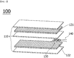
- the battery cell 100 may include a measuring unit 130 for measuring the electrolyte concentration between the positive electrode 121 and the separator, or between the negative electrode 122 and the separator 110.
- the measuring unit 130 is characterized in that the wire 140 drawn out of the battery cell 100 is connected.
- the measuring unit 130 has an insulating film 133 interposed between the first electrode plate 131 and the second electrode plate 132, and they are sequentially stacked.
- a wire 140 connected to the measuring unit includes a wire 141 connected to the first electrode plate 131 and a wire 142 connected to the second electrode plate 132, respectively, and the wire 140 is drawn out of the battery cell as shown in FIG. 1 .
- the measuring unit is inserted between the electrode and the separator 110 of the battery cell 100 to measure the concentration of the electrolyte between the separator and the electrode.
- the measuring unit is illustrated as being inserted between the negative electrode 122 and the separator 110, but may be inserted between the positive electrode 121 and the separator 110.
- the measuring unit does not necessarily need to be inserted between the electrode and the separator of the battery cell, and may be inserted at another position that can be inserted according to the size, shape, and structure of the battery cell.
- the insulating layer 133 of the measuring unit is interposed between the first electrode plate 131 and the second electrode plate 132 to absorb the electrolyte between the positive electrode 121 or the negative electrode 122 of the battery cell and the separator 110, and when a current is applied to the wire 140 connected to the first electrode plate 131 and the second plate 132, the resistance value may be measured to calculate the concentration of the electrolyte.
- the wires are drawn out after assembling the secondary battery, and it is possible to measure the real-time electrolyte concentration at any time even while using the battery.
- the insulating film 133 may be made of a porous film made of a polyolefin-based polymer material so that the first electrode plate 131 and the second electrode plate 132 may be electrically insulated, and the electrolyte may be easily absorbed and lithium ions may be moved smoothly. Further, the used material may be the same material used for the separator. In addition, when a short circuit is expected according to the insertion part of the measuring unit, it is also possible to attach an additional insulating film 134 to the outer surface of the electrode plate that needs to be electrically insulating as shown in FIGS. 3 and 4 .
- the first electrode plate and/or the second electrode plate have a through-hole having a columnar shape, as shown in one embodiment of FIGS. 2 to 4 .
- the through-holes formed in the first electrode plate and the second electrode plate are positioned so that their shape and position correspond to each other in a direction perpendicular to the electrode plate, the electrolyte on the outside of the measuring unit is more easily penetrated inside through the through hole. As a result, the electrolyte is quickly absorbed into the insulating film, whereby the concentration change of the electrolyte can be measured more quickly in real time.
- each of the through-holes preferably occupies 0.1% or more relative to the horizontal cross-sectional area of the first electrode plate and/or the second electrode plate before forming the through-hole.
- one or more through-holes are formed in the electrode plate, and the porosity of the electrode plate is determined according to the size and number of the through-holes.
- the porosity of the electrode plate is a value obtained by dividing the sum of the volumes of all the through-holes formed by the volume of the electrode plate before forming the through-holes, and the porosity of the electrode plate is preferably adjusted to a range similar to that of the insulating film absorbing the electrolyte.
- the porosity of the electrode plate is preferably adjusted to have a porosity of 30 to 45%, and more preferably adjusted to have a porosity of 34 to 42%.
- the through-hole in the form of a column having a constant diameter.
- the porosity of the electrode plate may be calculated as a value obtained by dividing the horizontal cross-sectional area of the through-hole by the horizontal cross-section of the electrode plate.
- the horizontal cross-sectional area of the through-hole does not exceed 45% of the electrode plate area. Even if it exceeds 45%, it is difficult to expect further improvement of electrolyte permeability, and if the through-hole is formed too large, the rigidity of the electrode plate may be deteriorated, which may cause a defect such as distortion during preparing a measuring unit or during inserting the battery cell.
- the penetration rate is more excellent when a plurality of through-holes are formed than when one through-hole is formed. Therefore, it is preferable to form two or more through-holes, and when considering the efficiency of the process and the excellent penetration rate, it is most preferable to form a plurality of through-holes having a horizontal cross-sectional area of 1 to 10% of the electrode plate area so that the porosity of the electrode plate becomes 30 to 45%.
- the porosity of the first electrode plate and/or the second electrode plate is preferably set to be 30 to 45%, more preferably 34 to 42% by one or more through-holes formed in the first electrode plate and/or the second electrode plate, excellent electrolyte penetration rate can be expected.
- the porosity exceeds 45%, it is difficult to obtain uniform quality during the manufacturing process, and the difficulty of manufacturing can increase rapidly by generation of defects, etc., which is not desirable in terms of securing the efficiency of the process, and in such a case, it is difficult to expect significant improvement in penetration rate.
- the porosity is less than 30%, the electrolyte penetration rate is lowered, which is not preferable.
- the thickness of the measuring unit of the present invention may be preferably 25 to 35 ⁇ m, more preferably 28 to 30 ⁇ m.
- the thickness of the measurement unit is preferably as thin as possible because it does not change the shape of the battery cell even after insertion.
- the mechanical strength of the measuring unit may be lowered, such that the measuring unit may be broken due to external impact or the laminated structure may be distorted during manufacturing.
- the measuring unit of the present invention when the measuring unit of the present invention is inserted between the electrode and the separator, one outer surface of the first electrode plate or the second electrode plate comes in contact with the electrode.
- the insulating layer 134 may be further provided on an outer surface of the electrode plate which is in contact with the electrode, thereby adding insulation.
- the first electrode plate and the second electrode plate may be made of one metal selected from the group consisting of aluminum, copper, and nickel or an alloy of two or more kinds thereof, and more preferably be made of aluminum or copper.
- the method for measuring the electrolyte concentration using the battery cell including the measuring unit of the present invention includes the following steps:
- the concentration of the electrolyte is usually proportional to the magnitude of the electrical conductivity and inversely proportional to the resistance value.
- electrical conductivity is greatly affected by temperature. Based on these characteristics, a unique temperature curve according to the electrical conductivity and concentration characteristics appears depending on the type of electrolyte.
- the electrolyte measurement principle of the present invention uses the above-described electrolyte concentration characteristic, and in step s5, the resistance value between the first electrode plate and the second electrode plate can be measured by applying a current to the wire, from which the approximate concentration of the electrolyte can be calculated. After measuring the temperatures of the electrolyte, and then the measured temperatures can be amended to an inherent temperature curve according to the type of electrolyte, to thereby obtain a precise electrolyte concentration measurement results.
- a temperature sensor may be separately installed for measuring the electrolyte temperature.
- the porosity of the electrode plate is determined by the sum of the horizontal cross-sectional areas of the through holes with respect to the horizontal cross-sectional area of the electrode plate.
- the horizontal cross-sectional area of each individual through hole is preferably in the range of 0.1 to 45% relative to the total area of the electrode plate prior to through hole formation.
- the measuring unit of the present invention is a stack of the first electrode plate, the insulating film, and the second electrode plate in sequence, and may further include an insulating film on the outer surface of the electrode plate in contact with the electrode of the battery cell.
- the total thickness of the measuring unit may be preferably 25 to 35 ⁇ m, more preferably 28 to 30 ⁇ m.
- a metal foil to be used as the first electrode plate and the second electrode plate is cut. Since the first electrode plate and the second electrode plate correspond to the size of the measuring unit, first, the type and the insertion site of the battery cell into which the measuring unit is to be inserted may be determined, and then may be appropriately adjusted and cut to an appropriate size for easy insertion.
- copper may be used as the metal foil material, but other metals such as aluminum and nickel may be used.
- the through hole can be adjusted in size in consideration of electrolyte penetration rate and stability of the electrode plate, and the shape of the through hole may be preferably in the form of a square column, but if the diameter is uniform, it may be manufactured in another column shape such as a cylinder or a triangular column.
- the insulating film used in the measuring unit may be manufactured by cutting the porous polymer material into sizes corresponding to the first electrode plate and the second electrode plate, and the same material as that used for the separator of the battery cell may also be used.
- the binder is applied to both surfaces of the insulating film to a thickness of 3 to 5 ⁇ m so that each of the first electrode plate and the second electrode plate can be attached to the insulating film.
- the thickness of the binder is too thin outside the above range, the stability of the measuring unit may be lowered. If the binder is too thick, the thickness of the whole measuring unit may be thickened. As such, when the binder is inserted into a battery cell the shape of the battery cell may be deformed.
- the first electrode plate and the second electrode plate are positioned on one surface and the other surface of the insulating film, respectively. At this time, when the through-holes formed in the first electrode plate and the second electrode plate are positioned to correspond to each other in the vertical direction perpendicular to the electrode plate, the electrolyte penetration rate is improved, so that the concentration changes in real time can be measured more quickly.
- a pressing step is performed.
- the laminate is torn or distorted due to pressure, it is preferable to carry out the pressing process after wrapping the laminate with a film that protects the surface of the laminate, preferably a PET film.
- the pressurizing process of applying pressure to the laminate is the same as the lamination process of conventional battery manufacturing.
- the film surrounding the surface of the pressed laminate is separated to prepare a measuring unit according to the present invention.
- an insulating film may be additionally attached to the outer side of the electrode plate to prevent the short circuit.
- Wires made of copper and/or other conductive materials are connected to the first and second electrode plates, respectively.
- the wire is inserted into the battery cell while being connected to the measuring unit, and depending on the insertion site, the wire may cause a short circuit in the battery cell. Therefore, when it is necessary to give insulation to the wire, it can be coated with an insulating material.
- the wire is drawn out and connected to a measuring device for measuring the resistance of the electrolyte.
- Production of the battery cell may be performed in the same manner as a conventional manufacturing process.
- the measuring unit according to the present invention when the measuring unit according to the present invention is inserted into the battery cell, it is preferable that the battery cell is made during the stacking step of the battery cell manufacturing process.
- the stacking process can be temporarily suspended, the measuring unit can be placed at a desired position, and then the insertion can be simply performed by resuming the stacking process to cover the measuring unit.
- the measuring unit is positioned between the separator and the electrode of the battery cell, and then the wire is drawn out to the outside. After drawing the wire to the outside, it is possible to seal by attaching the polymer film on the area opened by the insertion of the measuring unit and applying heat to the area, thereby maintaining a sealed state so that outside air does not flow into the inside.
- binders which are not described in detail herein, reference may be made to elements commonly used in the battery field, particularly in the lithium secondary battery field.
- a first electrode plate and a second electrode plate having a square shape of 30 mm in width and 30 mm in length were prepared. Both the first electrode plate and the second electrode plate were used by cutting a foil of copper material having a thickness of 6 ⁇ m.
- each of the individual through holes is a square shape of 6 mm in width and 6 mm in length, and each of the through holes is spaced apart from each other by 4 mm in the horizontal and vertical directions.
- the insulating film has a square shape of 35 mm in width and 35 mm in length, and a porous polyethylene material having a porosity of 41% was used.
- the thickness of the insulating film was 9 ⁇ m, and a binder was coated on both surfaces of the insulating film to form a binder layer having a thickness of 4 ⁇ m, respectively.
- a laminate was formed by adjusting the positions such that the through-holes formed in the first electrode plate and the second electrode plate correspond to each other in a direction perpendicular to the electrode plate while the insulating film is laminated so as to be interposed between the first electrode plate and the second electrode plate.
- the thickness of the prepared measuring unit was 29 ⁇ m, and the porosity of each electrode plate was 36% (horizontal cross section area of the through hole (6mm ⁇ 6mm) ⁇ 9 / horizontal cross section area of the electrode plate (30mm ⁇ 30mm)).
- the measuring unit was manufactured in the same manner as in Example 1 except that nine equal through holes are generated in the first and second electrode plates so that the horizontal cross-section of each individual through hole becomes a square shape of 2 mm in width and 2 mm in length, and each through hole is spaced 8 mm apart in the transverse and longitudinal directions.
- the thickness of the prepared measuring unit was 29 ⁇ m, and the porosity of the electrode plate was 4%.
- the measuring unit was manufactured in the same manner as in Example 1 except that a single through hole was created at the center of the first electrode plate and the second electrode plate so that the horizontal cross-section of each individual through hole became a square shape having a width of 18 mm and a length of 18 mm.
- the thickness of the prepared measuring unit was 29 ⁇ m, and the porosity of each electrode plate was 36%.
- a measuring unit was manufactured in the same manner as in Example 1, except that neither the first electrode plate nor the second electrode plate formed a through hole.
- the thickness of the prepared measuring unit was 29 ⁇ m, and the porosity of each electrode plate was 0%.
- Example 1 The difference of the measuring unit manufactured by each said Example and the comparative example is shown in Table 1 below. [Table 1] Division Whether through-hole is formed Through hole size No. of through holes Porosity Example 1 O width, length 6mm 9 36% Example 2 O width, length 2mm 9 4% Example 3 O width, length 18mm 1 36% Comparative Example 1 X - 0 0%
- the measuring unit according to the above Examples and Comparative Examples is prepared and sufficiently dried at room temperature, and then resistance measurement was started by connecting a resistance measuring device to the wire connected to the measuring unit.
- the measuring unit was impregnated in an electrolyte having an ion concentration of 0.5 M which is prepared by dissolving LiPF 6 in a co-solvent which is generated by mixing ethyl carbonate (EC) with ethyl methyl carbonate (EMC) in a 1 : 1 ratio for each of the measuring devices.
- electrolyte having an ion concentration of 0.5 M which is prepared by dissolving LiPF 6 in a co-solvent which is generated by mixing ethyl carbonate (EC) with ethyl methyl carbonate (EMC) in a 1 : 1 ratio for each of the measuring devices.
- the maximum penetration distance is a value obtained by dividing the minimum length of the portion of the insulating film covered by the electrode plate in half. For example, in Example 1, since the through holes are 4 mm apart from each other, the minimum length of the insulating film covered by the electrode plate is 4 mm, and the maximum penetration distance divided by 1/2 is 2 mm. In general, the electrolyte penetration rate is better when the maximum penetration distance is shorter.
- Example 1 the penetration time was the best result of 0.8 seconds.
- Example 2 even though there are nine through-holes as in Example 1, the penetration time was 3.4 seconds, which is significantly slower than in Example 1 even in view of the difference in the maximum penetration distance.
- the porosity is only 4%, which seems to be because the movement of the electrolyte is inhibited.
- Example 3 having the same porosity as Example 1, the penetration time was 7.1 seconds, which is slower than that of Example 2. As such, it can be seen that even when having the same porosity, the more the through-holes having a uniform pattern, the better the penetration rate.
- the penetration time can be further improved depending on the porosity and the method of forming the through holes.
- the porosity is preferably in the range of 30 to 45%, more preferably 34 to 42% similar to the range of the insulating film of the porous material, the penetration rate will be excellent.
- the horizontal cross-sectional area of each individual through hole is preferably 0.1% or more relative to the area of the electrode plate.
- a significant increase of the penetration effect is not expected when it exceeds 45% of the electrode plate area. Rather, as the rigidity of the measuring unit is lowered, there is a possibility that a defect may occur during manufacturing. Therefore, it is desirable to be within 45%.
- Example 2 in the case of Example 1 in which nine through-holes having a through-hole horizontal cross-sectional area of 4% of the electrode plate area are formed, it can be seen that the penetration rate is excellent.
- Example 1 As shown in Table 3, in the case of Example 1, it takes only 0.9 seconds to reflect the change in the electrolyte concentration in the measured value, from which it can be seen that the real-time electrolyte concentration can be measured substantially.
Landscapes
- Chemical & Material Sciences (AREA)
- Chemical Kinetics & Catalysis (AREA)
- Electrochemistry (AREA)
- General Chemical & Material Sciences (AREA)
- Engineering & Computer Science (AREA)
- Manufacturing & Machinery (AREA)
- Physics & Mathematics (AREA)
- General Physics & Mathematics (AREA)
- Secondary Cells (AREA)
Claims (13)
- Batteriezelle (100), umfassend eine Messeinheit, in welcher eine erste Elektrodenplatte (131), eine isolierende Folie (133) und eine zweite Elektrodenplatte (132) sequentiell gestapelt sind,wobei die Messeinheit (130) zwischen einem Separator (110) und einer Elektrode (121, 122) der Batteriezelle (100) eingesetzt ist, undwobei elektrische Drähte (141, 142), welche zu einer Außenseite der Batteriezelle (100) gezogen sind, mit der ersten Elektrodenplatte (131) bzw. der zweiten Elektrodenplatte (132) verbunden sind,dadurch gekennzeichnet, dass ein oder mehrere Durchgangslöcher an der ersten Elektrodenplatte und der zweiten Elektrodenplatte gebildet sind.
- Batteriezelle nach Anspruch 1, wobei die Durchgangslöcher, welche an der ersten Elektrodenplatte (131) und der zweiten Elektrodenplatte (132) gebildet sind, eine gleiche Form aufweisen.
- Batteriezelle nach Anspruch 1, wobei eine horizontale Querschnittsfläche jedes Durchgangslochs 0,1 bis 45 % einer horizontalen Querschnittsfläche der ersten Elektrodenplatte (131) oder der zweiten Elektrodenplatte (132) entspricht.
- Batteriezelle nach Anspruch 1, wobei eine Porosität der ersten Elektrodenplatte (131) und der zweiten Elektrodenplatte (132) 30 bis 45 % beträgt.
- Batteriezelle nach Anspruch 1, wobei eine Dicke der Messeinheit (130) 25 bis 35 µm beträgt.
- Batteriezelle nach Anspruch 1, wobei die isolierende Folie (134) ferner an der äußeren Fläche der ersten Elektrodenplatte (131) oder der zweiten Elektrodenplatte (132) in Kontakt mit der Elektrode (121, 122) umfasst ist.
- Batteriezelle nach Anspruch 1, wobei die erste Elektrodenplatte (131) und die zweite Elektrodenplatte (132) ein Metall oder eine Legierung aus zwei oder mehr Metallen ist, welche aus der Gruppe ausgewählt sind, bestehend aus Aluminium, Kupfer und Nickel.
- Batteriezelle nach Anspruch 1, wobei die isolierende Folie (133) aus einem gleichen Material wie dem des Separators (110) der Batteriezelle (100) hergestellt ist.
- Verfahren eines Messens einer Elektrolytkonzentration einer Sekundärbatterie, wobei das Verfahren umfasst:Herstellen einer Messeinheit, in welcher eine erste Elektrodenplatte (131), eine isolierende Folie (133) und eine zweite Elektrodenplatte (132) sequentiell gestapelt sind (s1);Verbinden elektrischer Drähte (141, 142) mit einem Ende der ersten Elektrodenplatte (131) und der zweiten Elektrodenplatte (132) (s2);Einsetzen der Messeinheit (130) in einen Raum zwischen der Elektrode (121, 122) der Batteriezelle (100) und dem Separator (110) (s3); undHerausziehen der elektrischen Drähte (141, 142) zu der Außenseite der Batteriezelle (s4);Berechnen einer Konzentration von Elektrolytionen, welche in der isolierenden Folie (133) enthalten sind, indem eine Messvorrichtung mit dem elektrischen Draht verbunden wird (s5),wobei ein oder mehrere Durchgangslöcher an der ersten Elektrodenplatte und der zweiten Elektrodenplatte aus Schritt s1 gebildet sind.
- Verfahren nach Anspruch 9, wobei die Elektrolytionenkonzentration in dem Schritt s5 unter Verwendung eines Widerstandswerts zwischen der ersten Elektrodenplatte (131) und der zweiten Elektrodenplatte (132) und einer Temperatur des Elektrolyten berechnet wird.
- Verfahren nach Anspruch 9, wobei eine horizontale Querschnittsfläche jedes Durchgangslochs 0,1 bis 45 % einer horizontalen Querschnittsfläche der ersten Elektrodenplatte (131) oder der zweiten Elektrodenplatte (132) entspricht.
- Verfahren nach Anspruch 9, wobei eine Porosität der ersten Elektrodenplatte (131) und der zweiten Elektrodenplatte (132) 30 bis 45 % beträgt.
- Verfahren nach Anspruch 9, wobei eine Dicke der Messeinheit (130) 25 bis 35 µm beträgt.
Applications Claiming Priority (2)
| Application Number | Priority Date | Filing Date | Title |
|---|---|---|---|
| KR1020180131467A KR102460808B1 (ko) | 2018-10-31 | 2018-10-31 | 전해액 이온 농도 측정부를 포함하는 전지셀 및 이를 이용한 전해액 농도 측정 방법 |
| PCT/KR2019/013836 WO2020091283A1 (ko) | 2018-10-31 | 2019-10-21 | 전해액 이온 농도 측정부를 포함하는 전지셀 및 이를 이용한 전해액 농도 측정 방법 |
Publications (3)
| Publication Number | Publication Date |
|---|---|
| EP3758129A1 EP3758129A1 (de) | 2020-12-30 |
| EP3758129A4 EP3758129A4 (de) | 2021-07-28 |
| EP3758129B1 true EP3758129B1 (de) | 2022-11-30 |
Family
ID=70464152
Family Applications (1)
| Application Number | Title | Priority Date | Filing Date |
|---|---|---|---|
| EP19879823.3A Active EP3758129B1 (de) | 2018-10-31 | 2019-10-21 | Batteriezelle mit elektrolytionenkonzentrationsmesseinheit und verfahren zur messung der elektrolytkonzentration unter verwendung davon |
Country Status (5)
| Country | Link |
|---|---|
| US (2) | US11881570B2 (de) |
| EP (1) | EP3758129B1 (de) |
| KR (1) | KR102460808B1 (de) |
| CN (1) | CN112005427B (de) |
| WO (1) | WO2020091283A1 (de) |
Families Citing this family (3)
| Publication number | Priority date | Publication date | Assignee | Title |
|---|---|---|---|---|
| KR102266657B1 (ko) | 2021-02-04 | 2021-06-18 | 주식회사 에이올코리아 | 방역천 제조방법, 방역천 제조방법으로 제조된 방역천, 방역천으로 제조되는 방역수단 |
| CN113013495B (zh) * | 2021-02-22 | 2025-07-04 | 福建星云电子股份有限公司 | 一种用于化成分容设备的电芯精度校准工装 |
| JP7351319B2 (ja) * | 2021-03-02 | 2023-09-27 | トヨタ自動車株式会社 | 演算装置および全固体電池システム |
Family Cites Families (16)
| Publication number | Priority date | Publication date | Assignee | Title |
|---|---|---|---|---|
| US3673551A (en) * | 1969-11-28 | 1972-06-27 | Molex Products Co | Integrated circuit terminal and method |
| JP4157317B2 (ja) | 2002-04-10 | 2008-10-01 | 株式会社日立製作所 | 状態検知装置及びこれを用いた各種装置 |
| KR200288338Y1 (ko) | 2002-06-01 | 2002-09-11 | 새한에너테크 주식회사 | 이온전도도 측정용 셀 |
| WO2009093684A1 (ja) * | 2008-01-24 | 2009-07-30 | Toyota Jidosha Kabushiki Kaisha | リチウムイオン二次電池、組電池、車両、電池搭載機器、電池システム、および、リチウムイオン二次電池の劣化検知方法 |
| JP2010170874A (ja) | 2009-01-23 | 2010-08-05 | Toyota Motor Corp | 組電池システム及び組電池の劣化検知方法 |
| JP5353339B2 (ja) | 2009-03-17 | 2013-11-27 | トヨタ自動車株式会社 | 電池システム、及び、ハイブリッド自動車 |
| US20130295424A1 (en) * | 2012-05-04 | 2013-11-07 | Dialog Semiconductor Gmbh | Electrolyte-Based Battery Cell, Method and System for Determining the State of Charge of Electrolyte-Based Batteries |
| CN103046084B (zh) * | 2012-12-20 | 2015-09-16 | 北京九能京通新能源科技有限公司 | 电解还原系统及电解还原方法 |
| CN104577236A (zh) * | 2013-10-24 | 2015-04-29 | 华为技术有限公司 | 一种植入传感器的蓄电池 |
| JP2015187949A (ja) | 2014-03-27 | 2015-10-29 | 株式会社日立製作所 | リチウムイオン二次電池 |
| JP2015191878A (ja) * | 2014-03-31 | 2015-11-02 | 株式会社日立製作所 | リチウムイオン二次電池システムおよびリチウムイオン二次電池の状態診断方法 |
| JP2016031894A (ja) | 2014-07-30 | 2016-03-07 | トヨタ自動車株式会社 | 二次電池システム |
| KR102036590B1 (ko) | 2015-09-17 | 2019-10-25 | 주식회사 엘지화학 | 접힘 방식으로 형태 변형이 가능한 구조의 이차전지용 전극 및 이를 포함하는 이차전지 |
| KR102041329B1 (ko) * | 2015-12-04 | 2019-11-06 | 주식회사 엘지화학 | 이차전지용 분리막의 성능 평가 방법과, 이를 위한 평가 장치 |
| JP6689512B2 (ja) * | 2016-03-30 | 2020-04-28 | エルジー・ケム・リミテッド | リチウム二次電池の製造方法 |
| US10090067B1 (en) | 2017-05-30 | 2018-10-02 | Seagate Technology Llc | Data storage device with rewritable in-place memory |
-
2018
- 2018-10-31 KR KR1020180131467A patent/KR102460808B1/ko active Active
-
2019
- 2019-10-21 WO PCT/KR2019/013836 patent/WO2020091283A1/ko not_active Ceased
- 2019-10-21 CN CN201980023044.7A patent/CN112005427B/zh active Active
- 2019-10-21 EP EP19879823.3A patent/EP3758129B1/de active Active
- 2019-10-21 US US17/044,362 patent/US11881570B2/en active Active
-
2023
- 2023-12-05 US US18/529,843 patent/US12243992B2/en active Active
Also Published As
| Publication number | Publication date |
|---|---|
| CN112005427B (zh) | 2024-06-18 |
| CN112005427A (zh) | 2020-11-27 |
| US12243992B2 (en) | 2025-03-04 |
| US11881570B2 (en) | 2024-01-23 |
| EP3758129A1 (de) | 2020-12-30 |
| KR102460808B1 (ko) | 2022-10-31 |
| WO2020091283A1 (ko) | 2020-05-07 |
| KR20200048878A (ko) | 2020-05-08 |
| EP3758129A4 (de) | 2021-07-28 |
| US20210043987A1 (en) | 2021-02-11 |
| US20240106018A1 (en) | 2024-03-28 |
Similar Documents
| Publication | Publication Date | Title |
|---|---|---|
| US12243992B2 (en) | Battery cell including electrolyte ion concentration measurement unit and method for measuring electrolyte concentration using same | |
| KR101847550B1 (ko) | 비수 전해액 이차 전지 및 당해 전지의 제조 방법 | |
| US8148010B2 (en) | Bipolar battery and battery assembly | |
| KR101806416B1 (ko) | 기준 전극(reference electrode)을 포함하는 리튬 이온 이차 전지 | |
| EP4033635B1 (de) | Vorrichtung zum aufladen/entladen einer batteriezelle | |
| KR102734360B1 (ko) | 내부 단락 유도를 위한 전기화학소자 및 이를 이용한 안전성 평가방법 | |
| CN112514129B (zh) | 锂二次电池 | |
| JP2011216408A (ja) | リチウム二次電池及びその製造方法 | |
| KR102656799B1 (ko) | 전지의 내부단락 유도장치, 이를 포함하는 전지 및 전지의 내부단락을 통한 안전성 평가방법 | |
| KR101520153B1 (ko) | 이차 전지용 파우치 셀 및 이의 제조방법 | |
| CN112335088A (zh) | 锂离子二次电池及其制造方法 | |
| KR101330357B1 (ko) | 전극, 전지 및 전극의 제조 방법 | |
| KR100509435B1 (ko) | 리튬이차전지 및 그 제조방법 | |
| JP2022166599A (ja) | 積層型固体電池ユニット及びその製造方法 | |
| JP2022528542A (ja) | 短絡誘導部材を含む電気化学素子及びそれを用いた安全性評価方法 | |
| KR20180032763A (ko) | 전극과 분리막이 부분 결착된 전극조립체 | |
| KR20140072794A (ko) | 비수전해질 이차 전지 팩 | |
| KR101656082B1 (ko) | 전극의 구성이 상이한 단위셀들을 포함하고 있는 전지셀 | |
| JP2023509610A (ja) | 金属とポリマー膜とを含む複合電極、製造方法、及び該複合電極を有するバッテリー | |
| JP2005347018A (ja) | バイポーラ電池の製造方法 | |
| US20250038361A1 (en) | Electrochemical energy storage element | |
| JP7681561B2 (ja) | 非水電解液二次電池 | |
| KR20140006722A (ko) | 이차전지의 제조방법 및 이에 따른 이차전지, 전기화학소자 | |
| KR200312088Y1 (ko) | 리튬이차전지 및 그 제조방법 | |
| KR20250151700A (ko) | 이차 전지용 음극, 전극 조립체 및 이를 포함하는 이차 전지 팩 |
Legal Events
| Date | Code | Title | Description |
|---|---|---|---|
| STAA | Information on the status of an ep patent application or granted ep patent |
Free format text: STATUS: THE INTERNATIONAL PUBLICATION HAS BEEN MADE |
|
| PUAI | Public reference made under article 153(3) epc to a published international application that has entered the european phase |
Free format text: ORIGINAL CODE: 0009012 |
|
| STAA | Information on the status of an ep patent application or granted ep patent |
Free format text: STATUS: REQUEST FOR EXAMINATION WAS MADE |
|
| 17P | Request for examination filed |
Effective date: 20200921 |
|
| AK | Designated contracting states |
Kind code of ref document: A1 Designated state(s): AL AT BE BG CH CY CZ DE DK EE ES FI FR GB GR HR HU IE IS IT LI LT LU LV MC MK MT NL NO PL PT RO RS SE SI SK SM TR |
|
| AX | Request for extension of the european patent |
Extension state: BA ME |
|
| A4 | Supplementary search report drawn up and despatched |
Effective date: 20210628 |
|
| RIC1 | Information provided on ipc code assigned before grant |
Ipc: G01N 27/413 20060101ALI20210622BHEP Ipc: H01M 10/48 20060101AFI20210622BHEP Ipc: H01M 10/0585 20100101ALI20210622BHEP Ipc: G01R 31/389 20190101ALI20210622BHEP Ipc: G01R 31/36 20200101ALI20210622BHEP Ipc: H01M 10/052 20100101ALI20210622BHEP Ipc: G01N 27/07 20060101ALI20210622BHEP Ipc: G01N 27/416 20060101ALI20210622BHEP Ipc: G01R 27/22 20060101ALI20210622BHEP Ipc: G01R 31/392 20190101ALI20210622BHEP Ipc: H01M 10/0525 20100101ALN20210622BHEP |
|
| RAP1 | Party data changed (applicant data changed or rights of an application transferred) |
Owner name: LG ENERGY SOLUTION LTD. |
|
| DAV | Request for validation of the european patent (deleted) | ||
| DAX | Request for extension of the european patent (deleted) | ||
| RAP3 | Party data changed (applicant data changed or rights of an application transferred) |
Owner name: LG ENERGY SOLUTION, LTD. |
|
| GRAP | Despatch of communication of intention to grant a patent |
Free format text: ORIGINAL CODE: EPIDOSNIGR1 |
|
| STAA | Information on the status of an ep patent application or granted ep patent |
Free format text: STATUS: GRANT OF PATENT IS INTENDED |
|
| RIC1 | Information provided on ipc code assigned before grant |
Ipc: H01M 10/0525 20100101ALN20220810BHEP Ipc: H01M 50/569 20210101ALI20220810BHEP Ipc: G01R 31/392 20190101ALI20220810BHEP Ipc: G01R 27/22 20060101ALI20220810BHEP Ipc: G01N 27/416 20060101ALI20220810BHEP Ipc: G01N 27/413 20060101ALI20220810BHEP Ipc: G01N 27/07 20060101ALI20220810BHEP Ipc: H01M 10/052 20100101ALI20220810BHEP Ipc: G01R 31/36 20200101ALI20220810BHEP Ipc: G01R 31/389 20190101ALI20220810BHEP Ipc: H01M 10/0585 20100101ALI20220810BHEP Ipc: H01M 10/48 20060101AFI20220810BHEP |
|
| INTG | Intention to grant announced |
Effective date: 20220913 |
|
| GRAS | Grant fee paid |
Free format text: ORIGINAL CODE: EPIDOSNIGR3 |
|
| GRAA | (expected) grant |
Free format text: ORIGINAL CODE: 0009210 |
|
| STAA | Information on the status of an ep patent application or granted ep patent |
Free format text: STATUS: THE PATENT HAS BEEN GRANTED |
|
| AK | Designated contracting states |
Kind code of ref document: B1 Designated state(s): AL AT BE BG CH CY CZ DE DK EE ES FI FR GB GR HR HU IE IS IT LI LT LU LV MC MK MT NL NO PL PT RO RS SE SI SK SM TR |
|
| REG | Reference to a national code |
Ref country code: CH Ref legal event code: EP Ref country code: GB Ref legal event code: FG4D |
|
| REG | Reference to a national code |
Ref country code: AT Ref legal event code: REF Ref document number: 1535375 Country of ref document: AT Kind code of ref document: T Effective date: 20221215 |
|
| REG | Reference to a national code |
Ref country code: IE Ref legal event code: FG4D |
|
| REG | Reference to a national code |
Ref country code: DE Ref legal event code: R096 Ref document number: 602019022732 Country of ref document: DE |
|
| REG | Reference to a national code |
Ref country code: LT Ref legal event code: MG9D |
|
| REG | Reference to a national code |
Ref country code: NL Ref legal event code: MP Effective date: 20221130 |
|
| PG25 | Lapsed in a contracting state [announced via postgrant information from national office to epo] |
Ref country code: SE Free format text: LAPSE BECAUSE OF FAILURE TO SUBMIT A TRANSLATION OF THE DESCRIPTION OR TO PAY THE FEE WITHIN THE PRESCRIBED TIME-LIMIT Effective date: 20221130 Ref country code: PT Free format text: LAPSE BECAUSE OF FAILURE TO SUBMIT A TRANSLATION OF THE DESCRIPTION OR TO PAY THE FEE WITHIN THE PRESCRIBED TIME-LIMIT Effective date: 20230331 Ref country code: NO Free format text: LAPSE BECAUSE OF FAILURE TO SUBMIT A TRANSLATION OF THE DESCRIPTION OR TO PAY THE FEE WITHIN THE PRESCRIBED TIME-LIMIT Effective date: 20230228 Ref country code: LT Free format text: LAPSE BECAUSE OF FAILURE TO SUBMIT A TRANSLATION OF THE DESCRIPTION OR TO PAY THE FEE WITHIN THE PRESCRIBED TIME-LIMIT Effective date: 20221130 Ref country code: FI Free format text: LAPSE BECAUSE OF FAILURE TO SUBMIT A TRANSLATION OF THE DESCRIPTION OR TO PAY THE FEE WITHIN THE PRESCRIBED TIME-LIMIT Effective date: 20221130 Ref country code: ES Free format text: LAPSE BECAUSE OF FAILURE TO SUBMIT A TRANSLATION OF THE DESCRIPTION OR TO PAY THE FEE WITHIN THE PRESCRIBED TIME-LIMIT Effective date: 20221130 |
|
| REG | Reference to a national code |
Ref country code: AT Ref legal event code: MK05 Ref document number: 1535375 Country of ref document: AT Kind code of ref document: T Effective date: 20221130 |
|
| PG25 | Lapsed in a contracting state [announced via postgrant information from national office to epo] |
Ref country code: RS Free format text: LAPSE BECAUSE OF FAILURE TO SUBMIT A TRANSLATION OF THE DESCRIPTION OR TO PAY THE FEE WITHIN THE PRESCRIBED TIME-LIMIT Effective date: 20221130 Ref country code: PL Free format text: LAPSE BECAUSE OF FAILURE TO SUBMIT A TRANSLATION OF THE DESCRIPTION OR TO PAY THE FEE WITHIN THE PRESCRIBED TIME-LIMIT Effective date: 20221130 Ref country code: LV Free format text: LAPSE BECAUSE OF FAILURE TO SUBMIT A TRANSLATION OF THE DESCRIPTION OR TO PAY THE FEE WITHIN THE PRESCRIBED TIME-LIMIT Effective date: 20221130 Ref country code: IS Free format text: LAPSE BECAUSE OF FAILURE TO SUBMIT A TRANSLATION OF THE DESCRIPTION OR TO PAY THE FEE WITHIN THE PRESCRIBED TIME-LIMIT Effective date: 20230330 Ref country code: HR Free format text: LAPSE BECAUSE OF FAILURE TO SUBMIT A TRANSLATION OF THE DESCRIPTION OR TO PAY THE FEE WITHIN THE PRESCRIBED TIME-LIMIT Effective date: 20221130 Ref country code: GR Free format text: LAPSE BECAUSE OF FAILURE TO SUBMIT A TRANSLATION OF THE DESCRIPTION OR TO PAY THE FEE WITHIN THE PRESCRIBED TIME-LIMIT Effective date: 20230301 |
|
| P01 | Opt-out of the competence of the unified patent court (upc) registered |
Effective date: 20230512 |
|
| PG25 | Lapsed in a contracting state [announced via postgrant information from national office to epo] |
Ref country code: NL Free format text: LAPSE BECAUSE OF FAILURE TO SUBMIT A TRANSLATION OF THE DESCRIPTION OR TO PAY THE FEE WITHIN THE PRESCRIBED TIME-LIMIT Effective date: 20221130 |
|
| PG25 | Lapsed in a contracting state [announced via postgrant information from national office to epo] |
Ref country code: SM Free format text: LAPSE BECAUSE OF FAILURE TO SUBMIT A TRANSLATION OF THE DESCRIPTION OR TO PAY THE FEE WITHIN THE PRESCRIBED TIME-LIMIT Effective date: 20221130 Ref country code: RO Free format text: LAPSE BECAUSE OF FAILURE TO SUBMIT A TRANSLATION OF THE DESCRIPTION OR TO PAY THE FEE WITHIN THE PRESCRIBED TIME-LIMIT Effective date: 20221130 Ref country code: EE Free format text: LAPSE BECAUSE OF FAILURE TO SUBMIT A TRANSLATION OF THE DESCRIPTION OR TO PAY THE FEE WITHIN THE PRESCRIBED TIME-LIMIT Effective date: 20221130 Ref country code: DK Free format text: LAPSE BECAUSE OF FAILURE TO SUBMIT A TRANSLATION OF THE DESCRIPTION OR TO PAY THE FEE WITHIN THE PRESCRIBED TIME-LIMIT Effective date: 20221130 Ref country code: CZ Free format text: LAPSE BECAUSE OF FAILURE TO SUBMIT A TRANSLATION OF THE DESCRIPTION OR TO PAY THE FEE WITHIN THE PRESCRIBED TIME-LIMIT Effective date: 20221130 Ref country code: AT Free format text: LAPSE BECAUSE OF FAILURE TO SUBMIT A TRANSLATION OF THE DESCRIPTION OR TO PAY THE FEE WITHIN THE PRESCRIBED TIME-LIMIT Effective date: 20221130 |
|
| PG25 | Lapsed in a contracting state [announced via postgrant information from national office to epo] |
Ref country code: SK Free format text: LAPSE BECAUSE OF FAILURE TO SUBMIT A TRANSLATION OF THE DESCRIPTION OR TO PAY THE FEE WITHIN THE PRESCRIBED TIME-LIMIT Effective date: 20221130 Ref country code: AL Free format text: LAPSE BECAUSE OF FAILURE TO SUBMIT A TRANSLATION OF THE DESCRIPTION OR TO PAY THE FEE WITHIN THE PRESCRIBED TIME-LIMIT Effective date: 20221130 |
|
| REG | Reference to a national code |
Ref country code: DE Ref legal event code: R097 Ref document number: 602019022732 Country of ref document: DE |
|
| PLBE | No opposition filed within time limit |
Free format text: ORIGINAL CODE: 0009261 |
|
| STAA | Information on the status of an ep patent application or granted ep patent |
Free format text: STATUS: NO OPPOSITION FILED WITHIN TIME LIMIT |
|
| 26N | No opposition filed |
Effective date: 20230831 |
|
| PG25 | Lapsed in a contracting state [announced via postgrant information from national office to epo] |
Ref country code: SI Free format text: LAPSE BECAUSE OF FAILURE TO SUBMIT A TRANSLATION OF THE DESCRIPTION OR TO PAY THE FEE WITHIN THE PRESCRIBED TIME-LIMIT Effective date: 20221130 |
|
| PG25 | Lapsed in a contracting state [announced via postgrant information from national office to epo] |
Ref country code: IT Free format text: LAPSE BECAUSE OF FAILURE TO SUBMIT A TRANSLATION OF THE DESCRIPTION OR TO PAY THE FEE WITHIN THE PRESCRIBED TIME-LIMIT Effective date: 20221130 Ref country code: MC Free format text: LAPSE BECAUSE OF FAILURE TO SUBMIT A TRANSLATION OF THE DESCRIPTION OR TO PAY THE FEE WITHIN THE PRESCRIBED TIME-LIMIT Effective date: 20221130 |
|
| REG | Reference to a national code |
Ref country code: CH Ref legal event code: PL |
|
| REG | Reference to a national code |
Ref country code: BE Ref legal event code: MM Effective date: 20231031 |
|
| PG25 | Lapsed in a contracting state [announced via postgrant information from national office to epo] |
Ref country code: LU Free format text: LAPSE BECAUSE OF NON-PAYMENT OF DUE FEES Effective date: 20231021 |
|
| PG25 | Lapsed in a contracting state [announced via postgrant information from national office to epo] |
Ref country code: LU Free format text: LAPSE BECAUSE OF NON-PAYMENT OF DUE FEES Effective date: 20231021 |
|
| PG25 | Lapsed in a contracting state [announced via postgrant information from national office to epo] |
Ref country code: CH Free format text: LAPSE BECAUSE OF NON-PAYMENT OF DUE FEES Effective date: 20231031 |
|
| PG25 | Lapsed in a contracting state [announced via postgrant information from national office to epo] |
Ref country code: CH Free format text: LAPSE BECAUSE OF NON-PAYMENT OF DUE FEES Effective date: 20231031 |
|
| PG25 | Lapsed in a contracting state [announced via postgrant information from national office to epo] |
Ref country code: BE Free format text: LAPSE BECAUSE OF NON-PAYMENT OF DUE FEES Effective date: 20231031 |
|
| PG25 | Lapsed in a contracting state [announced via postgrant information from national office to epo] |
Ref country code: IE Free format text: LAPSE BECAUSE OF NON-PAYMENT OF DUE FEES Effective date: 20231021 |
|
| PG25 | Lapsed in a contracting state [announced via postgrant information from national office to epo] |
Ref country code: IE Free format text: LAPSE BECAUSE OF NON-PAYMENT OF DUE FEES Effective date: 20231021 |
|
| PG25 | Lapsed in a contracting state [announced via postgrant information from national office to epo] |
Ref country code: BG Free format text: LAPSE BECAUSE OF FAILURE TO SUBMIT A TRANSLATION OF THE DESCRIPTION OR TO PAY THE FEE WITHIN THE PRESCRIBED TIME-LIMIT Effective date: 20221130 |
|
| PG25 | Lapsed in a contracting state [announced via postgrant information from national office to epo] |
Ref country code: BG Free format text: LAPSE BECAUSE OF FAILURE TO SUBMIT A TRANSLATION OF THE DESCRIPTION OR TO PAY THE FEE WITHIN THE PRESCRIBED TIME-LIMIT Effective date: 20221130 |
|
| PG25 | Lapsed in a contracting state [announced via postgrant information from national office to epo] |
Ref country code: CY Free format text: LAPSE BECAUSE OF FAILURE TO SUBMIT A TRANSLATION OF THE DESCRIPTION OR TO PAY THE FEE WITHIN THE PRESCRIBED TIME-LIMIT; INVALID AB INITIO Effective date: 20191021 |
|
| PG25 | Lapsed in a contracting state [announced via postgrant information from national office to epo] |
Ref country code: HU Free format text: LAPSE BECAUSE OF FAILURE TO SUBMIT A TRANSLATION OF THE DESCRIPTION OR TO PAY THE FEE WITHIN THE PRESCRIBED TIME-LIMIT; INVALID AB INITIO Effective date: 20191021 |
|
| PGFP | Annual fee paid to national office [announced via postgrant information from national office to epo] |
Ref country code: GB Payment date: 20250922 Year of fee payment: 7 |
|
| PGFP | Annual fee paid to national office [announced via postgrant information from national office to epo] |
Ref country code: FR Payment date: 20250925 Year of fee payment: 7 |
|
| PG25 | Lapsed in a contracting state [announced via postgrant information from national office to epo] |
Ref country code: TR Free format text: LAPSE BECAUSE OF FAILURE TO SUBMIT A TRANSLATION OF THE DESCRIPTION OR TO PAY THE FEE WITHIN THE PRESCRIBED TIME-LIMIT Effective date: 20221130 |
|
| PGFP | Annual fee paid to national office [announced via postgrant information from national office to epo] |
Ref country code: DE Payment date: 20250922 Year of fee payment: 7 |