EP3757405B1 - Zierklammer mit vierpunkthalterung - Google Patents
Zierklammer mit vierpunkthalterung Download PDFInfo
- Publication number
- EP3757405B1 EP3757405B1 EP20178522.7A EP20178522A EP3757405B1 EP 3757405 B1 EP3757405 B1 EP 3757405B1 EP 20178522 A EP20178522 A EP 20178522A EP 3757405 B1 EP3757405 B1 EP 3757405B1
- Authority
- EP
- European Patent Office
- Prior art keywords
- grommet
- pin
- fastener
- lead
- prong
- Prior art date
- Legal status (The legal status is an assumption and is not a legal conclusion. Google has not performed a legal analysis and makes no representation as to the accuracy of the status listed.)
- Active
Links
Images


Classifications
-
- F—MECHANICAL ENGINEERING; LIGHTING; HEATING; WEAPONS; BLASTING
- F16—ENGINEERING ELEMENTS AND UNITS; GENERAL MEASURES FOR PRODUCING AND MAINTAINING EFFECTIVE FUNCTIONING OF MACHINES OR INSTALLATIONS; THERMAL INSULATION IN GENERAL
- F16B—DEVICES FOR FASTENING OR SECURING CONSTRUCTIONAL ELEMENTS OR MACHINE PARTS TOGETHER, e.g. NAILS, BOLTS, CIRCLIPS, CLAMPS, CLIPS OR WEDGES; JOINTS OR JOINTING
- F16B21/00—Means for preventing relative axial movement of a pin, spigot, shaft or the like and a member surrounding it; Stud-and-socket releasable fastenings
- F16B21/09—Releasable fastening devices with a stud engaging a keyhole slot
-
- F—MECHANICAL ENGINEERING; LIGHTING; HEATING; WEAPONS; BLASTING
- F16—ENGINEERING ELEMENTS AND UNITS; GENERAL MEASURES FOR PRODUCING AND MAINTAINING EFFECTIVE FUNCTIONING OF MACHINES OR INSTALLATIONS; THERMAL INSULATION IN GENERAL
- F16B—DEVICES FOR FASTENING OR SECURING CONSTRUCTIONAL ELEMENTS OR MACHINE PARTS TOGETHER, e.g. NAILS, BOLTS, CIRCLIPS, CLAMPS, CLIPS OR WEDGES; JOINTS OR JOINTING
- F16B13/00—Dowels or other devices fastened in walls or the like by inserting them in holes made therein for that purpose
- F16B13/04—Dowels or other devices fastened in walls or the like by inserting them in holes made therein for that purpose with parts gripping in the hole or behind the reverse side of the wall after inserting from the front
- F16B13/08—Dowels or other devices fastened in walls or the like by inserting them in holes made therein for that purpose with parts gripping in the hole or behind the reverse side of the wall after inserting from the front with separate or non-separate gripping parts moved into their final position in relation to the body of the device without further manual operation
- F16B13/0891—Dowels or other devices fastened in walls or the like by inserting them in holes made therein for that purpose with parts gripping in the hole or behind the reverse side of the wall after inserting from the front with separate or non-separate gripping parts moved into their final position in relation to the body of the device without further manual operation with a locking element, e.g. wedge, key or ball moving along an inclined surface of the dowel body
-
- F—MECHANICAL ENGINEERING; LIGHTING; HEATING; WEAPONS; BLASTING
- F16—ENGINEERING ELEMENTS AND UNITS; GENERAL MEASURES FOR PRODUCING AND MAINTAINING EFFECTIVE FUNCTIONING OF MACHINES OR INSTALLATIONS; THERMAL INSULATION IN GENERAL
- F16B—DEVICES FOR FASTENING OR SECURING CONSTRUCTIONAL ELEMENTS OR MACHINE PARTS TOGETHER, e.g. NAILS, BOLTS, CIRCLIPS, CLAMPS, CLIPS OR WEDGES; JOINTS OR JOINTING
- F16B21/00—Means for preventing relative axial movement of a pin, spigot, shaft or the like and a member surrounding it; Stud-and-socket releasable fastenings
- F16B21/06—Releasable fastening devices with snap-action
- F16B21/07—Releasable fastening devices with snap-action in which the socket has a resilient part
- F16B21/073—Releasable fastening devices with snap-action in which the socket has a resilient part the socket having a resilient part on its inside
- F16B21/075—Releasable fastening devices with snap-action in which the socket has a resilient part the socket having a resilient part on its inside the socket having resilient parts on its inside and outside
-
- F—MECHANICAL ENGINEERING; LIGHTING; HEATING; WEAPONS; BLASTING
- F16—ENGINEERING ELEMENTS AND UNITS; GENERAL MEASURES FOR PRODUCING AND MAINTAINING EFFECTIVE FUNCTIONING OF MACHINES OR INSTALLATIONS; THERMAL INSULATION IN GENERAL
- F16B—DEVICES FOR FASTENING OR SECURING CONSTRUCTIONAL ELEMENTS OR MACHINE PARTS TOGETHER, e.g. NAILS, BOLTS, CIRCLIPS, CLAMPS, CLIPS OR WEDGES; JOINTS OR JOINTING
- F16B5/00—Joining sheets or plates, e.g. panels, to one another or to strips or bars parallel to them
- F16B5/06—Joining sheets or plates, e.g. panels, to one another or to strips or bars parallel to them by means of clamps or clips
- F16B5/0607—Joining sheets or plates, e.g. panels, to one another or to strips or bars parallel to them by means of clamps or clips joining sheets or plates to each other
- F16B5/0621—Joining sheets or plates, e.g. panels, to one another or to strips or bars parallel to them by means of clamps or clips joining sheets or plates to each other in parallel relationship
- F16B5/0664—Joining sheets or plates, e.g. panels, to one another or to strips or bars parallel to them by means of clamps or clips joining sheets or plates to each other in parallel relationship at least one of the sheets or plates having integrally formed or integrally connected snap-in-features
-
- F—MECHANICAL ENGINEERING; LIGHTING; HEATING; WEAPONS; BLASTING
- F16—ENGINEERING ELEMENTS AND UNITS; GENERAL MEASURES FOR PRODUCING AND MAINTAINING EFFECTIVE FUNCTIONING OF MACHINES OR INSTALLATIONS; THERMAL INSULATION IN GENERAL
- F16B—DEVICES FOR FASTENING OR SECURING CONSTRUCTIONAL ELEMENTS OR MACHINE PARTS TOGETHER, e.g. NAILS, BOLTS, CIRCLIPS, CLAMPS, CLIPS OR WEDGES; JOINTS OR JOINTING
- F16B21/00—Means for preventing relative axial movement of a pin, spigot, shaft or the like and a member surrounding it; Stud-and-socket releasable fastenings
- F16B21/06—Releasable fastening devices with snap-action
- F16B21/07—Releasable fastening devices with snap-action in which the socket has a resilient part
- F16B21/073—Releasable fastening devices with snap-action in which the socket has a resilient part the socket having a resilient part on its inside
-
- B—PERFORMING OPERATIONS; TRANSPORTING
- B60—VEHICLES IN GENERAL
- B60R—VEHICLES, VEHICLE FITTINGS, OR VEHICLE PARTS, NOT OTHERWISE PROVIDED FOR
- B60R13/00—Elements for body-finishing, identifying, or decorating; Arrangements or adaptations for advertising purposes
- B60R13/02—Internal Trim mouldings ; Internal Ledges; Wall liners for passenger compartments; Roof liners
- B60R13/0206—Arrangements of fasteners and clips specially adapted for attaching inner vehicle liners or mouldings
-
- F—MECHANICAL ENGINEERING; LIGHTING; HEATING; WEAPONS; BLASTING
- F16—ENGINEERING ELEMENTS AND UNITS; GENERAL MEASURES FOR PRODUCING AND MAINTAINING EFFECTIVE FUNCTIONING OF MACHINES OR INSTALLATIONS; THERMAL INSULATION IN GENERAL
- F16B—DEVICES FOR FASTENING OR SECURING CONSTRUCTIONAL ELEMENTS OR MACHINE PARTS TOGETHER, e.g. NAILS, BOLTS, CIRCLIPS, CLAMPS, CLIPS OR WEDGES; JOINTS OR JOINTING
- F16B21/00—Means for preventing relative axial movement of a pin, spigot, shaft or the like and a member surrounding it; Stud-and-socket releasable fastenings
- F16B21/06—Releasable fastening devices with snap-action
- F16B21/065—Releasable fastening devices with snap-action with an additional locking element
-
- F—MECHANICAL ENGINEERING; LIGHTING; HEATING; WEAPONS; BLASTING
- F16—ENGINEERING ELEMENTS AND UNITS; GENERAL MEASURES FOR PRODUCING AND MAINTAINING EFFECTIVE FUNCTIONING OF MACHINES OR INSTALLATIONS; THERMAL INSULATION IN GENERAL
- F16B—DEVICES FOR FASTENING OR SECURING CONSTRUCTIONAL ELEMENTS OR MACHINE PARTS TOGETHER, e.g. NAILS, BOLTS, CIRCLIPS, CLAMPS, CLIPS OR WEDGES; JOINTS OR JOINTING
- F16B21/00—Means for preventing relative axial movement of a pin, spigot, shaft or the like and a member surrounding it; Stud-and-socket releasable fastenings
- F16B21/10—Means for preventing relative axial movement of a pin, spigot, shaft or the like and a member surrounding it; Stud-and-socket releasable fastenings by separate parts
- F16B21/12—Means for preventing relative axial movement of a pin, spigot, shaft or the like and a member surrounding it; Stud-and-socket releasable fastenings by separate parts with locking-pins or split-pins thrust into holes
- F16B21/125—Means for preventing relative axial movement of a pin, spigot, shaft or the like and a member surrounding it; Stud-and-socket releasable fastenings by separate parts with locking-pins or split-pins thrust into holes radially resilient or with a snap-action member, e.g. elastic tooth, pawl with spring, resilient coil or wire
-
- F—MECHANICAL ENGINEERING; LIGHTING; HEATING; WEAPONS; BLASTING
- F16—ENGINEERING ELEMENTS AND UNITS; GENERAL MEASURES FOR PRODUCING AND MAINTAINING EFFECTIVE FUNCTIONING OF MACHINES OR INSTALLATIONS; THERMAL INSULATION IN GENERAL
- F16B—DEVICES FOR FASTENING OR SECURING CONSTRUCTIONAL ELEMENTS OR MACHINE PARTS TOGETHER, e.g. NAILS, BOLTS, CIRCLIPS, CLAMPS, CLIPS OR WEDGES; JOINTS OR JOINTING
- F16B5/00—Joining sheets or plates, e.g. panels, to one another or to strips or bars parallel to them
- F16B5/06—Joining sheets or plates, e.g. panels, to one another or to strips or bars parallel to them by means of clamps or clips
- F16B5/0607—Joining sheets or plates, e.g. panels, to one another or to strips or bars parallel to them by means of clamps or clips joining sheets or plates to each other
- F16B5/0621—Joining sheets or plates, e.g. panels, to one another or to strips or bars parallel to them by means of clamps or clips joining sheets or plates to each other in parallel relationship
- F16B5/0657—Joining sheets or plates, e.g. panels, to one another or to strips or bars parallel to them by means of clamps or clips joining sheets or plates to each other in parallel relationship at least one of the plates providing a raised structure, e.g. of the doghouse type, for connection with the clamps or clips of the other plate
Definitions
- Embodiments of the present disclosure generally relate to fasteners, and, more particularly, to a trim clip with four point retention.
- fasteners have been developed to secure panels to one another.
- vehicles include interior panels attached to body panels via a fastener inserted through respective slots in the panels. These fasteners permit the panels to be assembled together quickly.
- Certain known fasteners use a grommet with two retention points and a corresponding pin.
- the grommet attaches to a body panel and the pin is inserted through an interior panel and received by the grommet (e.g., to attach an interior portion to a vehicle door).
- the known grommets have little retention redundancy and are often difficult to install in the body panels.
- the known pins are often difficult to install in the grommets and are difficult to remove from the grommets during service (e.g., to service a power window assembly).
- a fastener is known from US 2013/0257025 A1 .
- a fastener according to claim 1 is provided.
- an example fastener in one aspect, includes a grommet and a pin.
- the grommet has a bottom set of lead in features.
- the pin is configured to removably snapably engage the grommet.
- the pin has a lead in feature.
- an example fastener in another aspect, includes a grommet and a pin.
- the grommet has a rounded bottom plate.
- the pin has a rounded stem configured to removably engage the grommet.
- an example fastener in another aspect, includes a grommet and a pin.
- the grommet includes a top plate, a bottom plate, a plurality of tapered prongs, and a plurality of retention fingers.
- the bottom plate is connected to the top plate and has a bottom set of lead in features.
- the plurality of tapered prongs is resiliently pivotably connected to the bottom plate and extends toward the top plate.
- the plurality of retention fingers is resiliently pivotably connected to the top plate and extends toward the bottom plate.
- the pin is configured to removably snapably engage the plurality of retention fingers.
- Embodiments of the present disclosure provide a fastener that firmly secures into a first panel, is simple to install, and permits relatively easy separation of a second panel from the first panel.
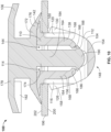
- FIGS. 1 , 2 , 3 , 8 , 9 , and 10 A first example fastener 100 according to an embodiment of the present disclosure is depicted in FIGS. 1 , 2 , 3 , 8 , 9 , and 10 .
- the fastener 100 includes a grommet 104 and a pin 106.
- the grommet 104 includes a top plate 110 and a bottom plate 112.
- the top plate 110 defines an opening 114.
- the grommet 104 further includes a first connector 116, a second connector 118, a third connector 120, and a fourth connector 122.
- the grommet 104 also has a first prong 126, a second prong 128, and a third prong 130.
- the grommet 104 also includes a fourth prong 132.
- the grommet 104 additionally includes a first retention finger 136, a second retention finger 138, and a flange 142.
- the top plate 110 is opposite the bottom plate 112.
- the first connector 116, the second connector 118, the third connector 120, and the fourth connector 122 connect the top plate 110 to the bottom plate 112.
- the first connector 116 and the second connector 118 are opposite the third connector 120 and the fourth connector 122.
- the first prong 126, the second prong 128, the third prong 130, and the fourth prong 132 are resiliently pivotably connected to and extend from the bottom plate 112 toward the top plate 110.
- the first prong 126 and the second prong 128 are opposite the third prong 130 and the fourth prong 132.
- the first prong 126, the second prong 128, the third prong 130, and the fourth prong 132 are outboard of the first connector 116, the second connector 118, the third connector 120, and the fourth connector 122.
- the first connector 116, the second connector 118, the third connector 120, and the fourth connector 122 are between the first prong 126, the second prong 128, the third prong 130, and the fourth prong 132.
- the first retention finger 136 and the second retention finger 138 are resiliently pivotably connected to and extend from the top plate 110 toward the bottom plate 112.
- the first retention finger 136 is opposite the second retention finger 138.
- the first retention finger 136 is inboard of the first connector 116 and the second connector 118.
- the second retention finger 138 is inboard of the third connector 120 and the fourth connector 122.
- the first retention finger 136 is between the first connector 116 and the second connector 118.
- the second retention finger 138 is between the third connector 120 and the fourth connector 122.
- the flange 142 is connected to and extends outwardly from the top plate 110.
- the flange 142 is generally perpendicular to the first connector 116, the second connector 118, the third connector 120, the fourth connector 122, the first retention finger 136, and the second retention finger 138.
- the flange 142 is generally parallel to the top plate 110 and the bottom plate 112.
- the top plate 110 has a top set of lead in features 144.
- the top set of lead in features 144 may include any type of lead in feature (e.g., chamfers, radii, ramps, etc.).
- the top set of lead in features 144 surround and at least partially define the opening 114.
- the bottom plate 112 includes a bottom set of lead in features 148.
- the bottom set of lead in features may include any type of lead in feature.
- the bottom set of lead in features 148 includes a first chamfer 150, a second chamfer 152, and a transverse radius 154.
- the transverse radius 154 is between the first chamfer 150 and the second chamfer 152.
- the bottom plate 112 is rounded via the bottom set of lead in features 148.
- each of the first prong 126, the second prong 128, the third prong 130, and the fourth prong 132 have a ramp 158 and a top end 160.
- the ramp 158 progressively widens in width from the bottom plate 112 to the top end 160.
- the ramp 158 is tapered to be narrower nearer the bottom plate 112 than the top end 160.
- each of the first retention finger 136 and the second retention finger 138 include a resilient portion 164 and a catch 166.
- the resilient portion 164 is resiliently pivotably connected to and extends generally perpendicularly from the top plate 110.
- the resilient portion 164 is generally parallel with the first connector 116, the second connector 118, the third connector 120, and the fourth connector 122.
- the catch 166 extends diagonally inboardly from the resilient portion 164. In some embodiments, the catch 166 is rounded.
- the catch 166 defines an external shoulder 168.
- the pin 106 includes a plate 172, an insert 174, a flange 176, and a connector portion 178.
- the pin 106 also includes a seal (not shown).
- the insert 174 is connected to and extends generally perpendicularly from the plate 172.
- the flange 176 is resiliently connected to and extends diagonally outwardly from the plate 172.
- the flange 176 surrounds the plate 172.
- the seal engages and surrounds the flange 176.
- the seal is formed of an elastomer.
- the connector portion 178 is connected to and extends generally perpendicularly from the plate 172.
- the plate 172 is between the connector portion 178 and the insert 174.
- the connector portion 178 includes a laterally extending retention barb 182.
- the insert 174 includes a stem 184, a first barb 186, and a second barb 188.
- the stem 184 also includes a lead in feature 190. More specifically, the stem 184 terminates in the lead in feature 190.
- the lead in feature 190 may be any type of lead in feature. In the example of FIG. 6 , the lead in feature 190 is a radius. Thus, in some embodiments, the stem 184 is rounded via the lead in feature 190.
- the stem 184 is connected to and extends from the plate 172.
- the first barb 186 and the second barb 188 extend outwardly from the stem 184.
- the lead in feature 190 is between and transitionally connected to the first barb 186 and the second barb 188. In some embodiments, the first barb 186 and the second barb 188 are rounded. With reference to FIG. 10 , the first barb 186 and the second barb 188 are shaped to matingly engage with the catches 166.
- the pin 106 is inserted into the grommet 104.
- the top set of lead in features 144 and the lead in feature 190 work together to guide the stem 184 into and through the opening 114.
- the first barb 186 and the second barb 188 encounter the catches 166.
- the first retention finger 136 and the second retention finger 138 resiliently pivot outwardly.
- the pin 106 is snapably engaged with the grommet 104. Further, when the pin 106 is assembled into the grommet 104, the plate 172 engages the top plate 110. Additionally, the flange 176 of the pin 106 engages the flange 142 of the grommet 104. The flange 176 of the pin 106 and the flange 142 of the grommet are shaped to matingly engage one another.
- the assembled fastener 100 is introduced into a slot 194 defined in a panel 196, as indicated by arrow 198.
- the grommet 104 may be introduced into the slot 194 without the pin 106 being assembled into the grommet 104.
- the bottom set of lead in features 148 guide the grommet 104 into the slot 194.
- the ramps 158 guide the fastener 100 into the slot 194.
- the fastener 100 As the fastener 100 is further inserted into the panel 196, the first prong 126, the second prong 128, the third prong 130, and the fourth prong 132 (shown in FIG. 3 ) resiliently pivot inwardly.
- the first prong 126, the second prong 128, the third prong 130, and the fourth prong 132 when the first prong 126, the second prong 128, the third prong 130, and the fourth prong 132 are pushed through the slot 194, the first prong 126, the second prong 128, the third prong 130, and the fourth prong 132 resiliently pivot outwardly.
- the fastener 100 is snapably engaged with the panel 196.
- the top ends 160 engage a bottom surface 200 of the panel 196.
- the flange 176 engages a top surface 202 of the panel 196.
- the flange 176 urges the pin 106 away from the top surface 202 to pull the first barb 186 and the second barb 188 tightly against the catches 166 and the top ends 160 against the bottom surface 200.
- the flange 176 provides a depth guard to prevent the pin 106 from being pushed completely through the panel 196.
- the pin 106 may be extracted from the grommet 104, as indicated by arrow 204.
- the first barb 186 and the second barb 188 encounter the catches 166.
- top ends 160 engage the bottom surface 200.
- the first barb 186 and the second barb 188 push against the catches 166 to respectively pivot the first retention finger 136 and the second retention finger 138 outwardly. It should be appreciated that the engagement of the top ends 160 against the bottom surface 200 provides a reaction force to the first barb 186 and the second barb 188 pushing against the catches 166.
- the pin 106 When the first barb 186 and the second barb 188 are pulled past the catches 166, the pin 106 is freed from the grommet 104 and the first retention finger 136 and the second retention finger 138 resiliently pivot inwardly. In other words, the pin 106 is removably snapably engaged with the grommet 104. It should be understood that the pin 106 may be reintroduced to snapably engage with the grommet 104 when the grommet 104 is seated in the panel 196. It should also be understood that the grommet 104 may be freed from the panel 196 by squeezing the first prong 126, the second prong 128, the third prong 130, and the fourth prong 132 inwardly from the bottom surface 200.
- the grommet 104 may be freed from the panel 196 by introducing a tool (e.g., pliers, a pick, an Allen wrench, etc.) through the opening 114 to pull the first prong 126, the second prong 128, the third prong 130, and the fourth prong 132 (shown in FIG. 3 ) inwardly.
- a tool e.g., pliers, a pick, an Allen wrench, etc.
- panel may refer to any component that may be attached or assembled to another component. Any of the panels described herein may be made of any suitable material, for example, a metal or plastic material.
- Embodiments of the present disclosure provide a fastener, and, more particularly, a grommet that securely and removably receives a pin and firmly seat into a panel.
- the pin includes a barbed stem and resilient flange.
- the grommet includes four prongs, two retention fingers, and has multiple sets of lead in features to guide the grommet into the panel and guide the pin into the grommet.
- the above example fastener 100 snapably fits into a panel with four points of contact via the grommet 104 and the pin 106 is removable from the grommet 104.
- the fastener 100 seats more securely into the panel than existing pin-and-grommet type fasteners.
- the pin 106 is more easily repeatedly removable from the grommet 104 than existing pin-and-grommet type fasteners.
- the fastener 100 may be reused, fewer fasteners may be damaged during installation and disassembly for service, work stoppages along assembly lines utilizing the fastener 100 may be reduced, and time and energy expended associated with the work stoppage may be reduced.
- the above-disclosed fastener 100 conserves resources and energy as compared to existing fasteners.
Landscapes
- Engineering & Computer Science (AREA)
- General Engineering & Computer Science (AREA)
- Mechanical Engineering (AREA)
- Insertion Pins And Rivets (AREA)
Claims (11)
- Befestigungselement (100), aufweisend:eine Durchführung (104) mit einer oberen Platte (110), zumindest einem Haltefinger (136, 138), der federnd schwenkbar mit der oberen Platte (110) verbunden ist, einer unteren Platte (112), die einen unteren Satz von Einführungsmerkmalen (148) beinhaltet, einer Öffnung (114), die sich durch die obere Platte (110) in Richtung der unteren Platte (112) erstreckt, und vier Zinken (126, 128, 130, 132), wobei jede Zinke (126, 128, 130, 132) federnd schwenkbar mit der unteren Platte (112) verbunden ist; undeinen Stift (106), der so konfiguriert ist, dass er mit der Durchführung (104) lösbar schnappbar in Eingriff kommt, wobei der Stift (106) ein Einführungsmerkmal (190) hat, das so konfiguriert ist, dass es den Stift (106) in die Öffnung (114) der Durchführung (104) führt, und einen oder zwei Widerhaken (186, 188), die, wenn der Stift (106) in die Öffnung (114) der Durchführung (104) eingeführt ist, den zumindest einen Haltefinger (136, 138) veranlasst, sich nach außen zu bewegen, bis eine Klinke (166) des zumindest einen Haltefingers (136, 138) mit einem Widerhaken (186, 188) des einen oder der beiden Widerhaken des Stiftes (106) schnappbar in Eingriff kommt.
- Befestigungselement (100) nach Anspruch 1, wobei zumindest eine der Zinken (126, 128, 130, 132) eine Rampe (158) und ein oberes Ende (160) beinhaltet.
- Befestigungselement (100) nach Anspruch 1, wobei die Durchführung (104) einen oberen Satz von
Einführungsmerkmalen (144) beinhaltet, der so konfiguriert ist, dass er den Stift (106) in die Durchführung (104) führt, wobei der obere Satz von Einführungsmerkmalen (144) optional zumindest eine Abschrägung beinhaltet. - Befestigungselement (100) nach Anspruch 1, wobei das Einführungsmerkmal (190) des Stifts (106) ein Radius ist.
- Befestigungselement (100) nach Anspruch 1, wobei sich die Klinke (166) nach innen erstreckt.
- Befestigungselement (100) nach Anspruch 1, wobei:die Durchführung (104) einen ersten Flansch (142) beinhaltet, undder Stift (106) einen zweiten Flansch (176) beinhaltet, wobei optional der zweite Flansch (176) so konfiguriert ist, dass er mit dem ersten Flansch (142) zusammenpassend im Eingriff ist.
- Befestigungselement (100) nach Anspruch 1, wobei der Stift (106) eine Platte (172) und einen Flansch (176) beinhaltet, der federnd schwenkbar mit der Platte (172) verbunden ist.
- Befestigungselement (100) nach Anspruch 1, wobei:die untere Platte (112) über den unteren Satz von Einführungsmerkmalen (148) abgerundet ist; undder Stift (106) einen Schaft (184) hat, der über das Einführungsmerkmal (190) abgerundet und so konfiguriert ist, dass er mit der Durchführung (104) lösbar in Eingriff kommt.
- Befestigungselement (100) nach Anspruch 8, wobei:der Widerhaken (186, 188) sich von dem Schaft (184) erstreckt, undder Widerhaken (186, 188) mit dem Haltefinger (136, 138) lösbar schnappbar in Eingriff kommt, oder wobei die Durchführung (104) eine Vielzahl von konischen Zinken (126, 128, 130, 132) hat.
- Befestigungselement (100) nach Anspruch 1,
wobei die untere Platte (112) mit der oberen Platte (110) verbunden ist,jede Zinke (126, 128, 130, 132) verjüngt ist und sich in Richtung der oberen Platte (110) erstreckt, undjeder Haltefinger (136, 138) sich in Richtung der unteren Platte (112) erstreckt. - Befestigungselement (100) nach Anspruch 9, wobei die obere Platte (110) einen oberen Satz von Einführungsmerkmalen (144) hat.
Applications Claiming Priority (2)
| Application Number | Priority Date | Filing Date | Title |
|---|---|---|---|
| US201962865391P | 2019-06-24 | 2019-06-24 | |
| US15/931,954 US11585365B2 (en) | 2019-06-24 | 2020-05-14 | Trim clip with four point retention |
Publications (2)
| Publication Number | Publication Date |
|---|---|
| EP3757405A1 EP3757405A1 (de) | 2020-12-30 |
| EP3757405B1 true EP3757405B1 (de) | 2024-08-07 |
Family
ID=71111199
Family Applications (1)
| Application Number | Title | Priority Date | Filing Date |
|---|---|---|---|
| EP20178522.7A Active EP3757405B1 (de) | 2019-06-24 | 2020-06-05 | Zierklammer mit vierpunkthalterung |
Country Status (5)
| Country | Link |
|---|---|
| US (1) | US11585365B2 (de) |
| EP (1) | EP3757405B1 (de) |
| KR (1) | KR102857798B1 (de) |
| CN (1) | CN112128191B (de) |
| BR (1) | BR102020012816A2 (de) |
Families Citing this family (6)
| Publication number | Priority date | Publication date | Assignee | Title |
|---|---|---|---|---|
| JP7230222B2 (ja) * | 2019-09-13 | 2023-02-28 | 株式会社パイオラックス | 留め具 |
| EP3907410B1 (de) * | 2020-05-07 | 2024-09-18 | Illinois Tool Works Inc. | Federklammer |
| DE102021111776A1 (de) * | 2020-05-11 | 2021-11-11 | Illinois Tool Works Inc. | Blindmontage-befestigungssystem |
| US20220001936A1 (en) * | 2020-07-06 | 2022-01-06 | Ford Global Technologies, Llc | Retention assemblies for automotive vehicles |
| US11815124B2 (en) * | 2021-03-05 | 2023-11-14 | Illinois Tool Works Inc. | Fastener assembly |
| WO2023219770A1 (en) * | 2022-05-13 | 2023-11-16 | Newfrey Llc | Serviceable stud and grommet assembly with low installation effort and high extraction force |
Citations (1)
| Publication number | Priority date | Publication date | Assignee | Title |
|---|---|---|---|---|
| US20130257025A1 (en) * | 2012-03-30 | 2013-10-03 | Toyota Jidosha Kabushiki Kaisha | Fixing clip and curtain airbag fixing apparatus |
Family Cites Families (45)
| Publication number | Priority date | Publication date | Assignee | Title |
|---|---|---|---|---|
| DE2626220C2 (de) | 1976-06-11 | 1984-05-03 | Itw-Ateco Gmbh, 2000 Norderstedt | Verbindung von Werkstücken |
| JPS5886912U (ja) | 1981-12-08 | 1983-06-13 | 株式会社ニフコ | パネルの留め具 |
| US5193961A (en) * | 1992-02-12 | 1993-03-16 | Illinois Tool Works Inc. | Pin and grommet |
| JPH0651518U (ja) | 1992-12-15 | 1994-07-15 | 株式会社ニフコ | 雌 具 |
| JP3491266B2 (ja) | 1994-06-28 | 2004-01-26 | 株式会社パイオラックス | 止め具 |
| US5533237A (en) | 1994-09-12 | 1996-07-09 | Emhart, Inc. | Grommet fastener assembly for automobiles |
| US5542158A (en) * | 1994-09-12 | 1996-08-06 | Emhart Inc. | Grommet fastener assembly for automobiles |
| US5704749A (en) * | 1996-07-19 | 1998-01-06 | Lockheed Martin Corporation | Panel aligning fastening system |
| US6279207B1 (en) * | 1999-02-01 | 2001-08-28 | Wtpa, Incorporated | Fasteners with increased holding power |
| US8627552B2 (en) * | 2001-06-25 | 2014-01-14 | Termax Corporation | Multicontact adaptive fastener clip |
| US20150321622A1 (en) * | 2002-06-07 | 2015-11-12 | Termax Corporation | Fastener Clip Over a Carrier |
| US6691380B2 (en) * | 2001-07-31 | 2004-02-17 | Eustathios Vassiliou Revocable Trust | Fasteners of increased holding power |
| JP2003072599A (ja) | 2001-09-05 | 2003-03-12 | Piolax Inc | 防水型クリップ |
| US6796006B2 (en) | 2002-04-25 | 2004-09-28 | Illinois Tool Works Inc. | Rib clip |
| JP2005527752A (ja) * | 2002-05-28 | 2005-09-15 | ニューフレイ リミテッド ライアビリティ カンパニー | 弾性クリップ式ファスナ及びその製造方法 |
| US10336265B2 (en) * | 2015-10-21 | 2019-07-02 | Termax Llc | Fastener clip over a carrier secured with hooks |
| US7204000B2 (en) * | 2003-10-13 | 2007-04-17 | Newfrey Llc | Fastener for fixed rib applications |
| US20060005363A1 (en) * | 2004-07-06 | 2006-01-12 | Reiter Howard J | Grommet snap fastening device |
| US9533718B2 (en) * | 2005-02-09 | 2017-01-03 | Termax Corporation | Continously adaptive fastener clip |
| JP2006336821A (ja) * | 2005-06-06 | 2006-12-14 | Nippon Pop Rivets & Fasteners Ltd | 高固定強度の固定具 |
| KR100970986B1 (ko) | 2005-06-08 | 2010-07-20 | 한국 티알더블류 자동차부품산업 주식회사 | 플라스틱 파스너 |
| US7401388B2 (en) | 2005-09-06 | 2008-07-22 | Illinois Tool Works Inc. | Rib clip |
| US7954206B2 (en) * | 2007-04-19 | 2011-06-07 | Illinois Tool Works Inc. | Pin and grommet fastener assembly |
| JP4704446B2 (ja) * | 2008-01-24 | 2011-06-15 | 株式会社ニフコ | クリップ |
| JP4540726B2 (ja) * | 2008-07-04 | 2010-09-08 | 大和化成工業株式会社 | 二部材組付け構造 |
| EP2175146A3 (de) * | 2008-10-10 | 2012-01-25 | Newfrey LLC | Befestigungselement und Befestigungsanordnung |
| BRPI1008677A2 (pt) * | 2009-03-06 | 2016-03-08 | Illinois Tool Works | aperfeiçoamentos em prendedores para fixação de acessórios em painéis de veículos. |
| US8683662B2 (en) | 2009-03-13 | 2014-04-01 | Illinois Tool Works Inc. | Piercing rib clip |
| ITTO20090321A1 (it) | 2009-04-23 | 2010-10-24 | Illinois Tool Works | Dispositivo di ritegno a scatto per un perno, in particolare per collegare elementi di carrozzeria di veicoli |
| DE202009011986U1 (de) * | 2009-08-28 | 2009-12-10 | Illinois Tool Works Inc., Glenview | Vorrichtung zur Verbindung zweier Bauteile |
| EP2714375A1 (de) * | 2011-06-02 | 2014-04-09 | A. Raymond et Cie | Durch dreidimensionales drucken hergestellte befestigungselemente |
| JP5771126B2 (ja) * | 2011-11-11 | 2015-08-26 | 株式会社ニフコ | クリップ |
| WO2013184590A1 (en) * | 2012-06-05 | 2013-12-12 | Illinois Tool Works Inc. | Adaptable mating fastener assembly |
| JP5653400B2 (ja) * | 2012-09-28 | 2015-01-14 | ポップリベット・ファスナー株式会社 | クリップ |
| USD759476S1 (en) * | 2013-06-18 | 2016-06-21 | Daiwa Kasei Kogyo Kabushiki Kaisha | Clip |
| WO2014205056A1 (en) * | 2013-06-20 | 2014-12-24 | Illinois Tool Works Inc. | Push-in fastener |
| DE202015101103U1 (de) | 2015-03-06 | 2016-06-09 | Böllhoff Verbindungstechnik GmbH | Steckkupplung aus Kupplungselement und Kugelzapfen |
| US9914408B2 (en) * | 2015-10-21 | 2018-03-13 | Termax Llc | Fastener clip over a carrier secured with barbs |
| US9835190B2 (en) * | 2016-04-05 | 2017-12-05 | GM Global Technology Operations LLC | Stud clip insert for panel hole |
| BR112019008348A2 (pt) | 2016-10-26 | 2019-10-01 | Illinois Tool Works | conjuntos de fecho herméticos a fluido |
| WO2019040301A1 (en) | 2017-08-22 | 2019-02-28 | Illinois Tool Works Inc. | MUTUAL LOCKING CLAMPS |
| CN210371479U (zh) | 2018-09-24 | 2020-04-21 | 特迈驰有限责任公司 | 紧固件夹组件 |
| CN111550479B (zh) | 2019-02-12 | 2024-04-26 | 特迈驰有限责任公司 | 带有稳定肩袢的紧固夹 |
| EP3779215A1 (de) | 2019-08-16 | 2021-02-17 | Termax LLC | Pfeilspitzenförmiger befestigungsclip mit widerhaken |
| EP3779216B1 (de) | 2019-08-16 | 2025-01-01 | Termax LLC | Umgossene metall-kunststoff-klammer |
-
2020
- 2020-05-14 US US15/931,954 patent/US11585365B2/en active Active
- 2020-06-05 EP EP20178522.7A patent/EP3757405B1/de active Active
- 2020-06-23 KR KR1020200076451A patent/KR102857798B1/ko active Active
- 2020-06-23 BR BR102020012816-7A patent/BR102020012816A2/pt unknown
- 2020-06-23 CN CN202010579757.6A patent/CN112128191B/zh active Active
Patent Citations (1)
| Publication number | Priority date | Publication date | Assignee | Title |
|---|---|---|---|---|
| US20130257025A1 (en) * | 2012-03-30 | 2013-10-03 | Toyota Jidosha Kabushiki Kaisha | Fixing clip and curtain airbag fixing apparatus |
Also Published As
| Publication number | Publication date |
|---|---|
| US11585365B2 (en) | 2023-02-21 |
| EP3757405A1 (de) | 2020-12-30 |
| CN112128191A (zh) | 2020-12-25 |
| BR102020012816A2 (pt) | 2021-04-06 |
| US20200400180A1 (en) | 2020-12-24 |
| KR102857798B1 (ko) | 2025-09-09 |
| CN112128191B (zh) | 2024-11-01 |
| KR20210000279A (ko) | 2021-01-04 |
Similar Documents
| Publication | Publication Date | Title |
|---|---|---|
| EP3757405B1 (de) | Zierklammer mit vierpunkthalterung | |
| US10202084B2 (en) | System for fastening a door module to a car door | |
| US6796006B2 (en) | Rib clip | |
| CN101312859B (zh) | 一种紧固件及其使用方法 | |
| US7017239B2 (en) | Component connection system | |
| US5441417A (en) | Electrical grounding stud | |
| US4874276A (en) | Fastener | |
| US20080066266A1 (en) | Fastener assembly | |
| US9590401B2 (en) | Cable retainer device and method for retaining cable in an aircraft | |
| US9866003B2 (en) | Self-indexing nut plate | |
| US7204000B2 (en) | Fastener for fixed rib applications | |
| EP0794353A1 (de) | Seilklemme | |
| EP2381553A2 (de) | Klammer | |
| CN107645995A (zh) | 可重复使用的紧固夹具组件 | |
| US11519441B2 (en) | Tree fastener removal assemblies and methods therefor | |
| EP3246580B1 (de) | Verriegelungshalterungssystem für automobilanordnung | |
| US11255365B2 (en) | Fastener assembly | |
| US20160123053A1 (en) | Baggage door | |
| US10090654B1 (en) | Junction box assembly with eyelet terminal cover retention system and removable eyelet terminal cover | |
| US11882906B2 (en) | Dual engagement fastener | |
| CN111664153A (zh) | 铆钉型紧固件 | |
| EP3786467A1 (de) | Ergonomische schachtelförmge mutternsicherung | |
| DE10210383B4 (de) | Befestigungsfeder | |
| US11772577B2 (en) | Serviceable shoe-clip fastener for vehicle trim attachment | |
| JP2008008361A (ja) | クランプ |
Legal Events
| Date | Code | Title | Description |
|---|---|---|---|
| PUAI | Public reference made under article 153(3) epc to a published international application that has entered the european phase |
Free format text: ORIGINAL CODE: 0009012 |
|
| STAA | Information on the status of an ep patent application or granted ep patent |
Free format text: STATUS: THE APPLICATION HAS BEEN PUBLISHED |
|
| AK | Designated contracting states |
Kind code of ref document: A1 Designated state(s): AL AT BE BG CH CY CZ DE DK EE ES FI FR GB GR HR HU IE IS IT LI LT LU LV MC MK MT NL NO PL PT RO RS SE SI SK SM TR |
|
| AX | Request for extension of the european patent |
Extension state: BA ME |
|
| STAA | Information on the status of an ep patent application or granted ep patent |
Free format text: STATUS: REQUEST FOR EXAMINATION WAS MADE |
|
| 17P | Request for examination filed |
Effective date: 20210625 |
|
| RBV | Designated contracting states (corrected) |
Designated state(s): AL AT BE BG CH CY CZ DE DK EE ES FI FR GB GR HR HU IE IS IT LI LT LU LV MC MK MT NL NO PL PT RO RS SE SI SK SM TR |
|
| STAA | Information on the status of an ep patent application or granted ep patent |
Free format text: STATUS: EXAMINATION IS IN PROGRESS |
|
| 17Q | First examination report despatched |
Effective date: 20221207 |
|
| GRAP | Despatch of communication of intention to grant a patent |
Free format text: ORIGINAL CODE: EPIDOSNIGR1 |
|
| STAA | Information on the status of an ep patent application or granted ep patent |
Free format text: STATUS: GRANT OF PATENT IS INTENDED |
|
| INTG | Intention to grant announced |
Effective date: 20240319 |
|
| RIN1 | Information on inventor provided before grant (corrected) |
Inventor name: STELTZ, JEFFREY J. |
|
| P01 | Opt-out of the competence of the unified patent court (upc) registered |
Effective date: 20240416 |
|
| GRAS | Grant fee paid |
Free format text: ORIGINAL CODE: EPIDOSNIGR3 |
|
| GRAA | (expected) grant |
Free format text: ORIGINAL CODE: 0009210 |
|
| STAA | Information on the status of an ep patent application or granted ep patent |
Free format text: STATUS: THE PATENT HAS BEEN GRANTED |
|
| AK | Designated contracting states |
Kind code of ref document: B1 Designated state(s): AL AT BE BG CH CY CZ DE DK EE ES FI FR GB GR HR HU IE IS IT LI LT LU LV MC MK MT NL NO PL PT RO RS SE SI SK SM TR |
|
| REG | Reference to a national code |
Ref country code: GB Ref legal event code: FG4D |
|
| REG | Reference to a national code |
Ref country code: CH Ref legal event code: EP |
|
| REG | Reference to a national code |
Ref country code: IE Ref legal event code: FG4D |
|
| REG | Reference to a national code |
Ref country code: DE Ref legal event code: R096 Ref document number: 602020035175 Country of ref document: DE |
|
| REG | Reference to a national code |
Ref country code: LT Ref legal event code: MG9D |
|
| REG | Reference to a national code |
Ref country code: NL Ref legal event code: MP Effective date: 20240807 |
|
| PG25 | Lapsed in a contracting state [announced via postgrant information from national office to epo] |
Ref country code: NO Free format text: LAPSE BECAUSE OF FAILURE TO SUBMIT A TRANSLATION OF THE DESCRIPTION OR TO PAY THE FEE WITHIN THE PRESCRIBED TIME-LIMIT Effective date: 20241107 |
|
| REG | Reference to a national code |
Ref country code: AT Ref legal event code: MK05 Ref document number: 1711226 Country of ref document: AT Kind code of ref document: T Effective date: 20240807 |
|
| PG25 | Lapsed in a contracting state [announced via postgrant information from national office to epo] |
Ref country code: NL Free format text: LAPSE BECAUSE OF FAILURE TO SUBMIT A TRANSLATION OF THE DESCRIPTION OR TO PAY THE FEE WITHIN THE PRESCRIBED TIME-LIMIT Effective date: 20240807 Ref country code: FI Free format text: LAPSE BECAUSE OF FAILURE TO SUBMIT A TRANSLATION OF THE DESCRIPTION OR TO PAY THE FEE WITHIN THE PRESCRIBED TIME-LIMIT Effective date: 20240807 Ref country code: PT Free format text: LAPSE BECAUSE OF FAILURE TO SUBMIT A TRANSLATION OF THE DESCRIPTION OR TO PAY THE FEE WITHIN THE PRESCRIBED TIME-LIMIT Effective date: 20241209 Ref country code: GR Free format text: LAPSE BECAUSE OF FAILURE TO SUBMIT A TRANSLATION OF THE DESCRIPTION OR TO PAY THE FEE WITHIN THE PRESCRIBED TIME-LIMIT Effective date: 20241108 Ref country code: PL Free format text: LAPSE BECAUSE OF FAILURE TO SUBMIT A TRANSLATION OF THE DESCRIPTION OR TO PAY THE FEE WITHIN THE PRESCRIBED TIME-LIMIT Effective date: 20240807 |
|
| PG25 | Lapsed in a contracting state [announced via postgrant information from national office to epo] |
Ref country code: BG Free format text: LAPSE BECAUSE OF FAILURE TO SUBMIT A TRANSLATION OF THE DESCRIPTION OR TO PAY THE FEE WITHIN THE PRESCRIBED TIME-LIMIT Effective date: 20240807 |
|
| PG25 | Lapsed in a contracting state [announced via postgrant information from national office to epo] |
Ref country code: LV Free format text: LAPSE BECAUSE OF FAILURE TO SUBMIT A TRANSLATION OF THE DESCRIPTION OR TO PAY THE FEE WITHIN THE PRESCRIBED TIME-LIMIT Effective date: 20240807 |
|
| PG25 | Lapsed in a contracting state [announced via postgrant information from national office to epo] |
Ref country code: AT Free format text: LAPSE BECAUSE OF FAILURE TO SUBMIT A TRANSLATION OF THE DESCRIPTION OR TO PAY THE FEE WITHIN THE PRESCRIBED TIME-LIMIT Effective date: 20240807 Ref country code: IS Free format text: LAPSE BECAUSE OF FAILURE TO SUBMIT A TRANSLATION OF THE DESCRIPTION OR TO PAY THE FEE WITHIN THE PRESCRIBED TIME-LIMIT Effective date: 20241207 |
|
| PG25 | Lapsed in a contracting state [announced via postgrant information from national office to epo] |
Ref country code: HR Free format text: LAPSE BECAUSE OF FAILURE TO SUBMIT A TRANSLATION OF THE DESCRIPTION OR TO PAY THE FEE WITHIN THE PRESCRIBED TIME-LIMIT Effective date: 20240807 |
|
| PG25 | Lapsed in a contracting state [announced via postgrant information from national office to epo] |
Ref country code: ES Free format text: LAPSE BECAUSE OF FAILURE TO SUBMIT A TRANSLATION OF THE DESCRIPTION OR TO PAY THE FEE WITHIN THE PRESCRIBED TIME-LIMIT Effective date: 20240807 Ref country code: RS Free format text: LAPSE BECAUSE OF FAILURE TO SUBMIT A TRANSLATION OF THE DESCRIPTION OR TO PAY THE FEE WITHIN THE PRESCRIBED TIME-LIMIT Effective date: 20241107 |
|
| PG25 | Lapsed in a contracting state [announced via postgrant information from national office to epo] |
Ref country code: RS Free format text: LAPSE BECAUSE OF FAILURE TO SUBMIT A TRANSLATION OF THE DESCRIPTION OR TO PAY THE FEE WITHIN THE PRESCRIBED TIME-LIMIT Effective date: 20241107 Ref country code: PT Free format text: LAPSE BECAUSE OF FAILURE TO SUBMIT A TRANSLATION OF THE DESCRIPTION OR TO PAY THE FEE WITHIN THE PRESCRIBED TIME-LIMIT Effective date: 20241209 Ref country code: PL Free format text: LAPSE BECAUSE OF FAILURE TO SUBMIT A TRANSLATION OF THE DESCRIPTION OR TO PAY THE FEE WITHIN THE PRESCRIBED TIME-LIMIT Effective date: 20240807 Ref country code: NO Free format text: LAPSE BECAUSE OF FAILURE TO SUBMIT A TRANSLATION OF THE DESCRIPTION OR TO PAY THE FEE WITHIN THE PRESCRIBED TIME-LIMIT Effective date: 20241107 Ref country code: NL Free format text: LAPSE BECAUSE OF FAILURE TO SUBMIT A TRANSLATION OF THE DESCRIPTION OR TO PAY THE FEE WITHIN THE PRESCRIBED TIME-LIMIT Effective date: 20240807 Ref country code: LV Free format text: LAPSE BECAUSE OF FAILURE TO SUBMIT A TRANSLATION OF THE DESCRIPTION OR TO PAY THE FEE WITHIN THE PRESCRIBED TIME-LIMIT Effective date: 20240807 Ref country code: IS Free format text: LAPSE BECAUSE OF FAILURE TO SUBMIT A TRANSLATION OF THE DESCRIPTION OR TO PAY THE FEE WITHIN THE PRESCRIBED TIME-LIMIT Effective date: 20241207 Ref country code: HR Free format text: LAPSE BECAUSE OF FAILURE TO SUBMIT A TRANSLATION OF THE DESCRIPTION OR TO PAY THE FEE WITHIN THE PRESCRIBED TIME-LIMIT Effective date: 20240807 Ref country code: GR Free format text: LAPSE BECAUSE OF FAILURE TO SUBMIT A TRANSLATION OF THE DESCRIPTION OR TO PAY THE FEE WITHIN THE PRESCRIBED TIME-LIMIT Effective date: 20241108 Ref country code: FI Free format text: LAPSE BECAUSE OF FAILURE TO SUBMIT A TRANSLATION OF THE DESCRIPTION OR TO PAY THE FEE WITHIN THE PRESCRIBED TIME-LIMIT Effective date: 20240807 Ref country code: ES Free format text: LAPSE BECAUSE OF FAILURE TO SUBMIT A TRANSLATION OF THE DESCRIPTION OR TO PAY THE FEE WITHIN THE PRESCRIBED TIME-LIMIT Effective date: 20240807 Ref country code: BG Free format text: LAPSE BECAUSE OF FAILURE TO SUBMIT A TRANSLATION OF THE DESCRIPTION OR TO PAY THE FEE WITHIN THE PRESCRIBED TIME-LIMIT Effective date: 20240807 Ref country code: AT Free format text: LAPSE BECAUSE OF FAILURE TO SUBMIT A TRANSLATION OF THE DESCRIPTION OR TO PAY THE FEE WITHIN THE PRESCRIBED TIME-LIMIT Effective date: 20240807 |
|
| PG25 | Lapsed in a contracting state [announced via postgrant information from national office to epo] |
Ref country code: DK Free format text: LAPSE BECAUSE OF FAILURE TO SUBMIT A TRANSLATION OF THE DESCRIPTION OR TO PAY THE FEE WITHIN THE PRESCRIBED TIME-LIMIT Effective date: 20240807 Ref country code: SM Free format text: LAPSE BECAUSE OF FAILURE TO SUBMIT A TRANSLATION OF THE DESCRIPTION OR TO PAY THE FEE WITHIN THE PRESCRIBED TIME-LIMIT Effective date: 20240807 |
|
| PG25 | Lapsed in a contracting state [announced via postgrant information from national office to epo] |
Ref country code: EE Free format text: LAPSE BECAUSE OF FAILURE TO SUBMIT A TRANSLATION OF THE DESCRIPTION OR TO PAY THE FEE WITHIN THE PRESCRIBED TIME-LIMIT Effective date: 20240807 |
|
| PG25 | Lapsed in a contracting state [announced via postgrant information from national office to epo] |
Ref country code: CZ Free format text: LAPSE BECAUSE OF FAILURE TO SUBMIT A TRANSLATION OF THE DESCRIPTION OR TO PAY THE FEE WITHIN THE PRESCRIBED TIME-LIMIT Effective date: 20240807 |
|
| PG25 | Lapsed in a contracting state [announced via postgrant information from national office to epo] |
Ref country code: SK Free format text: LAPSE BECAUSE OF FAILURE TO SUBMIT A TRANSLATION OF THE DESCRIPTION OR TO PAY THE FEE WITHIN THE PRESCRIBED TIME-LIMIT Effective date: 20240807 |
|
| REG | Reference to a national code |
Ref country code: DE Ref legal event code: R097 Ref document number: 602020035175 Country of ref document: DE |
|
| PLBE | No opposition filed within time limit |
Free format text: ORIGINAL CODE: 0009261 |
|
| STAA | Information on the status of an ep patent application or granted ep patent |
Free format text: STATUS: NO OPPOSITION FILED WITHIN TIME LIMIT |
|
| PGFP | Annual fee paid to national office [announced via postgrant information from national office to epo] |
Ref country code: DE Payment date: 20250627 Year of fee payment: 6 |
|
| 26N | No opposition filed |
Effective date: 20250508 |
|
| PGFP | Annual fee paid to national office [announced via postgrant information from national office to epo] |
Ref country code: FR Payment date: 20250625 Year of fee payment: 6 |
|
| PG25 | Lapsed in a contracting state [announced via postgrant information from national office to epo] |
Ref country code: SE Free format text: LAPSE BECAUSE OF FAILURE TO SUBMIT A TRANSLATION OF THE DESCRIPTION OR TO PAY THE FEE WITHIN THE PRESCRIBED TIME-LIMIT Effective date: 20240807 |
|
| REG | Reference to a national code |
Ref country code: CH Ref legal event code: H13 Free format text: ST27 STATUS EVENT CODE: U-0-0-H10-H13 (AS PROVIDED BY THE NATIONAL OFFICE) Effective date: 20260127 |
|
| PG25 | Lapsed in a contracting state [announced via postgrant information from national office to epo] |
Ref country code: MC Free format text: LAPSE BECAUSE OF FAILURE TO SUBMIT A TRANSLATION OF THE DESCRIPTION OR TO PAY THE FEE WITHIN THE PRESCRIBED TIME-LIMIT Effective date: 20240807 |