EP3779216B1 - Umgossene metall-kunststoff-klammer - Google Patents
Umgossene metall-kunststoff-klammer Download PDFInfo
- Publication number
- EP3779216B1 EP3779216B1 EP20190453.9A EP20190453A EP3779216B1 EP 3779216 B1 EP3779216 B1 EP 3779216B1 EP 20190453 A EP20190453 A EP 20190453A EP 3779216 B1 EP3779216 B1 EP 3779216B1
- Authority
- EP
- European Patent Office
- Prior art keywords
- piece
- blade
- fastener
- clip
- fastener clip
- Prior art date
- Legal status (The legal status is an assumption and is not a legal conclusion. Google has not performed a legal analysis and makes no representation as to the accuracy of the status listed.)
- Active
Links
Images


Classifications
-
- F—MECHANICAL ENGINEERING; LIGHTING; HEATING; WEAPONS; BLASTING
- F16—ENGINEERING ELEMENTS AND UNITS; GENERAL MEASURES FOR PRODUCING AND MAINTAINING EFFECTIVE FUNCTIONING OF MACHINES OR INSTALLATIONS; THERMAL INSULATION IN GENERAL
- F16B—DEVICES FOR FASTENING OR SECURING CONSTRUCTIONAL ELEMENTS OR MACHINE PARTS TOGETHER, e.g. NAILS, BOLTS, CIRCLIPS, CLAMPS, CLIPS OR WEDGES; JOINTS OR JOINTING
- F16B21/00—Means for preventing relative axial movement of a pin, spigot, shaft or the like and a member surrounding it; Stud-and-socket releasable fastenings
- F16B21/06—Releasable fastening devices with snap-action
- F16B21/08—Releasable fastening devices with snap-action in which the stud, pin, or spigot has a resilient part
-
- F—MECHANICAL ENGINEERING; LIGHTING; HEATING; WEAPONS; BLASTING
- F16—ENGINEERING ELEMENTS AND UNITS; GENERAL MEASURES FOR PRODUCING AND MAINTAINING EFFECTIVE FUNCTIONING OF MACHINES OR INSTALLATIONS; THERMAL INSULATION IN GENERAL
- F16B—DEVICES FOR FASTENING OR SECURING CONSTRUCTIONAL ELEMENTS OR MACHINE PARTS TOGETHER, e.g. NAILS, BOLTS, CIRCLIPS, CLAMPS, CLIPS OR WEDGES; JOINTS OR JOINTING
- F16B21/00—Means for preventing relative axial movement of a pin, spigot, shaft or the like and a member surrounding it; Stud-and-socket releasable fastenings
- F16B21/06—Releasable fastening devices with snap-action
- F16B21/07—Releasable fastening devices with snap-action in which the socket has a resilient part
- F16B21/073—Releasable fastening devices with snap-action in which the socket has a resilient part the socket having a resilient part on its inside
- F16B21/075—Releasable fastening devices with snap-action in which the socket has a resilient part the socket having a resilient part on its inside the socket having resilient parts on its inside and outside
-
- B—PERFORMING OPERATIONS; TRANSPORTING
- B60—VEHICLES IN GENERAL
- B60R—VEHICLES, VEHICLE FITTINGS, OR VEHICLE PARTS, NOT OTHERWISE PROVIDED FOR
- B60R13/00—Elements for body-finishing, identifying, or decorating; Arrangements or adaptations for advertising purposes
- B60R13/02—Internal Trim mouldings ; Internal Ledges; Wall liners for passenger compartments; Roof liners
-
- B—PERFORMING OPERATIONS; TRANSPORTING
- B60—VEHICLES IN GENERAL
- B60R—VEHICLES, VEHICLE FITTINGS, OR VEHICLE PARTS, NOT OTHERWISE PROVIDED FOR
- B60R13/00—Elements for body-finishing, identifying, or decorating; Arrangements or adaptations for advertising purposes
- B60R13/04—External Ornamental or guard strips; Ornamental inscriptive devices thereon
-
- F—MECHANICAL ENGINEERING; LIGHTING; HEATING; WEAPONS; BLASTING
- F16—ENGINEERING ELEMENTS AND UNITS; GENERAL MEASURES FOR PRODUCING AND MAINTAINING EFFECTIVE FUNCTIONING OF MACHINES OR INSTALLATIONS; THERMAL INSULATION IN GENERAL
- F16B—DEVICES FOR FASTENING OR SECURING CONSTRUCTIONAL ELEMENTS OR MACHINE PARTS TOGETHER, e.g. NAILS, BOLTS, CIRCLIPS, CLAMPS, CLIPS OR WEDGES; JOINTS OR JOINTING
- F16B21/00—Means for preventing relative axial movement of a pin, spigot, shaft or the like and a member surrounding it; Stud-and-socket releasable fastenings
- F16B21/06—Releasable fastening devices with snap-action
- F16B21/08—Releasable fastening devices with snap-action in which the stud, pin, or spigot has a resilient part
- F16B21/086—Releasable fastening devices with snap-action in which the stud, pin, or spigot has a resilient part the shank of the stud, pin or spigot having elevations, ribs, fins or prongs intended for deformation or tilting predominantly in a direction perpendicular to the direction of insertion
-
- F—MECHANICAL ENGINEERING; LIGHTING; HEATING; WEAPONS; BLASTING
- F16—ENGINEERING ELEMENTS AND UNITS; GENERAL MEASURES FOR PRODUCING AND MAINTAINING EFFECTIVE FUNCTIONING OF MACHINES OR INSTALLATIONS; THERMAL INSULATION IN GENERAL
- F16B—DEVICES FOR FASTENING OR SECURING CONSTRUCTIONAL ELEMENTS OR MACHINE PARTS TOGETHER, e.g. NAILS, BOLTS, CIRCLIPS, CLAMPS, CLIPS OR WEDGES; JOINTS OR JOINTING
- F16B5/00—Joining sheets or plates, e.g. panels, to one another or to strips or bars parallel to them
- F16B5/06—Joining sheets or plates, e.g. panels, to one another or to strips or bars parallel to them by means of clamps or clips
- F16B5/0607—Joining sheets or plates, e.g. panels, to one another or to strips or bars parallel to them by means of clamps or clips joining sheets or plates to each other
- F16B5/0621—Joining sheets or plates, e.g. panels, to one another or to strips or bars parallel to them by means of clamps or clips joining sheets or plates to each other in parallel relationship
- F16B5/065—Joining sheets or plates, e.g. panels, to one another or to strips or bars parallel to them by means of clamps or clips joining sheets or plates to each other in parallel relationship the plates being one on top of the other and distanced from each other, e.g. by using protrusions to keep contact and distance
-
- F—MECHANICAL ENGINEERING; LIGHTING; HEATING; WEAPONS; BLASTING
- F16—ENGINEERING ELEMENTS AND UNITS; GENERAL MEASURES FOR PRODUCING AND MAINTAINING EFFECTIVE FUNCTIONING OF MACHINES OR INSTALLATIONS; THERMAL INSULATION IN GENERAL
- F16B—DEVICES FOR FASTENING OR SECURING CONSTRUCTIONAL ELEMENTS OR MACHINE PARTS TOGETHER, e.g. NAILS, BOLTS, CIRCLIPS, CLAMPS, CLIPS OR WEDGES; JOINTS OR JOINTING
- F16B5/00—Joining sheets or plates, e.g. panels, to one another or to strips or bars parallel to them
- F16B5/06—Joining sheets or plates, e.g. panels, to one another or to strips or bars parallel to them by means of clamps or clips
- F16B5/0607—Joining sheets or plates, e.g. panels, to one another or to strips or bars parallel to them by means of clamps or clips joining sheets or plates to each other
- F16B5/0621—Joining sheets or plates, e.g. panels, to one another or to strips or bars parallel to them by means of clamps or clips joining sheets or plates to each other in parallel relationship
- F16B5/0657—Joining sheets or plates, e.g. panels, to one another or to strips or bars parallel to them by means of clamps or clips joining sheets or plates to each other in parallel relationship at least one of the plates providing a raised structure, e.g. of the doghouse type, for connection with the clamps or clips of the other plate
Definitions
- the invention relates generally to devices for fastening objects, and more particularly to a fastener clip assembly for insertion into an engagement structure, such as a vehicle chassis, a hollow substrate, a wall, a plate, or any suitable surface.
- an engagement structure such as a vehicle chassis, a hollow substrate, a wall, a plate, or any suitable surface.
- Fastener clips are known, for example, from US 2015/321622 A1 and US 2002/001502 A1 . Further, a number of devices and fasteners are currently available for fastening panels, such as body panels and automobile interior trim piece panels, to the chassis of a vehicle.
- a body panel refers to, for example, any interior or exterior body panel on a vehicle, a plastic interior trim piece, door panel, headliner or any interior trim piece. Additionally, the panel may be any suitable exterior body panel, such as a fender, bumper, quarter panel or door panel.
- the chassis of the vehicle may include any substrate, plate, body panel, structural framework, chassis component or subcomponent, wall or any suitable object.
- Fastener clips such as two-piece fasteners (multi-piece) are known for attaching body panels to an automobile chassis. Two-piece fasteners are used so that if the panels are removed after original installation, such as to service the components in the door, they may be pulled apart so that one portion remains attached to the sheet metal while the other remains attached to the trim panel. The two pieces may also be reattached after separation.
- two-piece fasteners require manufacturing of multiple pieces and labor-intensive assembly of the two pieces and thus are relatively expensive.
- One-piece fasteners are typically less expensive than two or multi piece fasteners.
- One-piece fasteners have a base to attach to a body panel and a blade attached to the base and wings attached at least to the top of the blade at a tip of the fastener for fastening to a frame slot.
- the forces on the wings are unequal since the wing closest to the slot edge will experience higher wing compression while the other wing will have insufficient springing force to engage the slot.
- the clip is forced into the slot, such high forces on one wing may cause the wing to break off thus rendering the fastener incapable of fastening the body panel to the frame.
- the broken, damaged or weakened wing can cause detachment of the body panel or contribute to rattles.
- the wings of conventional fasteners have a sharp, unsmooth groove to engage the edge of the frame slot.
- the sharp edges of the frame slot cut into the softer plastic and cut the groove.
- the slots are typically formed in the frame of the vehicle, such as in an inner roof or door sheet metal structure, by punching the sheet metal. As the punch enters the sheet metal, the outer part of the sheet metal is pushed toward the inside and a metal puncture or ridge is formed on the inside of the sheet metal. The resulting slot edge on the outer part of the slot is relatively smooth; however, the inner part of the slot edge is sharp and rough.
- Conventional fasteners typically do not adequately secure the panel to the vehicle chassis having variations in slot size and location or sheet metal with different curvature or thicknesses throughout.
- Conventional single piece fasteners do not self-align themselves when the fastener and the body panel are misaligned and are prone to wing breakage such that the fastener cannot be re-attached.
- conventional fasteners are not suitable when subjected to a variety of environmental conditions, such as in the presence of vibration at various levels of amplitude and frequency. For example, conventional fasteners of this type typically do not prevent or minimize the amount of buzzing, rattling or any other type of noise that may cause attention to the occupants of the vehicle or otherwise weaken the attachment.
- Conventional fasteners do not adequately accommodate various levels of production tolerances, such as various dimensions amongst, for example, the body panels as well as the vehicle chassis.
- conventional fastener devices typically do not self-align nor adequately fasten to a range of sheet metal thicknesses and do not minimize or eliminate buzzing and rattling and do not sufficiently accommodate variations in production tolerances.
- wear, squeaks, rattles, buzzing, corrosion and loss of elasticity and loss of sealing may result, especially after years of vehicle operation and exposure to vibration, heat, humidity, and other environmental conditions.
- Figure 1 is a perspective view of a fastener clip assembly, in accordance with some embodiments.
- fastener clip 100 is configured to fasten together top surface 300 and bottom surface 400.
- Blade 210 which extends from surface 400, is configured to receive and be secured to fastener clip 100.
- blade 210 may be molded onto surface 400. In other embodiments, blade 210 may be attached to surface 400 using various other means.
- fastener clip 100 may be configured to be inserted through slot 250 of top surface 300 and to secure itself to the top surface 300.
- the fastener clip assembly is configured to fasten together top surface 300 and bottom surface 400 based at least upon the fastener clip being secured to slot 250 of surface 300 and to blade 210 of surface 400.
- surface 400 may be part of a panel and surface 300 may be part of the chassis/frame of an automobile. Accordingly, the fastener clip assembly may be configured to fasten together a panel to the chassis/frame of an automobile.
- Figure 2 is a perspective view of two pieces of a fastener clip, in accordance with some embodiments.
- Figure 3 is another perspective view of two pieces of a fastener clip, in accordance with some embodiments.
- Figure 4 is yet another perspective view of two pieces of a fastener clip, in accordance with some embodiments.
- Figure 5 is yet another perspective view of two pieces of a fastener clip, in accordance with some embodiments.
- fastener clip 100 may be made of at least two different materials.
- the first material may be one with high elasticity/springiness (such as metal, for example) to allow the clip to spring between at least two positions to facilitate insertion and engagement.
- the second material may be a softer material (such as plastic, for example) to allow the clip to form better and/or safer contact with the surfaces with which the clip is to engage. Such softer material may prevent, for example, early wear of either the clip or the surfaces engaged by the clip.
- fastener clip 100 may be made with a combination of metal and an injection moldable plastic.
- the metal portion may be made first, using sheet metal made of steel and a stamping process, for example. The plastic may be then injected around the metal. In some embodiments, the plastic may be injected both to the inside and to the outside of the metal clip as will be described further elsewhere.
- fastener clip 100 comprises first piece 101 and a second piece 102 that are combined to form the fastener clip 100.
- first piece 101 may be made of an elastic/springy material such as metal
- second piece 102 may be made of a softer material such as plastic.
- first piece 101 includes a pair of legs 60 joined at a head portion 70.
- the pair of legs 60 form a clip opening 80 at an opposite end of the head portion 70 to allow entry of a blade 210 to which clip 100 is configured to attach.
- each of legs 60 terminate at the end opposite to head portion 70 to feet 200.
- first piece 101 may also include, on each leg 60, windows 90 and 92 that may be configured to permit the molded material of piece 102 to flow between the inside and the outside of piece 101. In some embodiments, molding the material of second piece 102 between the inside and the outside of first piece 102 significantly strengthens the coupling between first piece 101 and second piece 102. Additionally, first piece 101 may include protrusions, such as protrusion 94, to further enhance the coupling between first piece 101 and second piece 102.
- first piece 101 may also include a pair of barbs on each of the legs 60 (four barbs, in one embodiment).
- barbs 65 are each attached to the sides of the legs 60. Based at least on barbs 65 being sharp at their ends and of greater hardness than the material of blade 210, the barbs are configured to dig into and attach the first piece 101 to the blade 210 upon inserting the fastener clip 100 over the blade 210.
- the blade 210 upon inserting fastener clip 100 over blade 210, the blade 210 is configured to bend barbs 65 apart, and the barbs 65 are configured to spring back against the blade 210. During insertion, blade 210 slides upwards towards barbs 65, which are also pushed apart by blade 210. Upon inserting the clip 100 over blade 210, barbs 65 are configured to dig into the material of blade 210 to further increase the removal effort required to separate the clip from the blade. Furthermore, barbs 65 provide additional support for the coupling between the fastener clip 100 and the blade 210.
- second piece 102 includes a pair of legs 62 joined at a head portion 72.
- the pair of legs 62 form a clip opening 82 at an opposite end of the head portion 72 to allow entry of a blade 210 to which clip 100 is configured to attach.
- each of legs 62 terminate at the end opposite to head portion 72 to feet 202.
- second piece 102 may be injection molded around first piece 101. In some embodiments, portions of second piece 102 may be molded to the outside of the first piece 101 while other portions of second piece 102 may be molded to the inside of the first piece 101.
- the second piece 102 may be molded as one continuous piece and may be weaved inside and outside of first piece 101 through windows 90 and 92, for example.
- legs 62 and feet 202 may be to the outside of first piece 101 while head portion 72 and inner pieces 96 may be to the inside of first piece 101.
- weaving the second piece in such a manner significantly enhances the coupling between the first and second pieces.
- the head portion 72 being on the inside of head portion 70 is configured to engage blade 210 tightly to enhance the coupling between the clip 100 and blade 210.
- each leg 62 may include a sloping portion such that, while engaging slot 250, legs 63 are configured to spring in and then spring back when clip 100 engages the slot 250.
- each leg 62 may include at least one depressed portion 600. The depressed portion 600 is formed and is configured to engage a portion of the slot 250 of surface 300.
- slot 250 may have any shape such as a circle, a square, a rectangle, a pentagon, a hexagon, a polygon, an n-sided polygon where n is a whole number, an ellipse, an oval, etc.
- the depressed portion 600 may include, for example, an abrupt edge, a gradual angled edge, such as a curve, a single angled edge, a discrete multiangled edge or a pointed edge.
- the depressed portion 600 may be formed on the depressed part of each leg 60 so as to engage the slot 250 to increase an extraction force for the fastener clip 20 from the slot 250.
- the depressed portion 600 may be sized to suitably engage slot 250 of the surface 300 in order to obtain the desired level of extraction force.
- the depressed portion 600 may be a depression formed on legs 62.
- the size and shape of the depressed portion 600 may be formed in any suitable manner in order to permit relatively easy insertion of the fastener clip 100 into the slot 250 while increasing the extraction force.
- Figure 6 is a perspective view of a blade configured to receive a fastener clip, in accordance with some embodiments.
- blade 210 is configured to receive and attach to fastener clip 100.
- Blade 210 may be either attached to or be part of surface 400.
- surface 400 is made of plastic, for example, the structure of blade 210 may be molded as part of surface/structure 400.
- surface/structure 400 may be an automobile panel that is to be attached to the automobile chassis.
- guiding structures 750 positioned on either side of blade 210, are configured to guide fastener clip 100 over blade 210 as the fastener clip is being inserted over the blade.
- guiding structures 750 are configured to provide additional stability to the coupling between blade 210 and fastener clip 100 after installation.
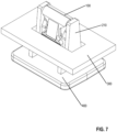
- Figure 7 is a perspective view of a fastener clip attached to a chassis, in accordance with some embodiments.
- the fastener clip assembly is configured to join together two surfaces such as surfaces 300 and 400.
- Fastener clip 100 is configured to fit over and attach to blade 210 that is attached to surface 400, and in addition fastener clip 100 is configured to removably attach to the slot in surface 200.
- the fastener clip system may be used to fasten together a body panel to the chassis of an automobile.
Landscapes
- Engineering & Computer Science (AREA)
- General Engineering & Computer Science (AREA)
- Mechanical Engineering (AREA)
- Connection Of Plates (AREA)
- Insertion Pins And Rivets (AREA)
Claims (10)
- Befestigungsklammer (100), umfassend:ein erstes Stück (101), welches aus einem ersten Material hergestellt ist, wobei das erste Material elastisch ist, wobei das erste Stück (101) umfasst:ein Paar Beine (60), welche an einem Kopfabschnitt (70) verbunden sind, wobei die Beine (60) an einem gegenüberliegenden Ende des Kopfabschnitts (70) eine Klammeröffnung (80) bilden;ein oder mehrere Paare Widerhaken (65), welche an das Paar Beine (60) gekoppelt sind,
wobei die Widerhaken (65) dazu konfiguriert sind, sich in eine Klinge (210) einzugraben, wobei die Klinge (210) dazu konfiguriert ist, mit einer Platte gekoppelt zu werden, wobei die Befestigungsklammer (100) dazu konfiguriert ist, über der Klinge (210) befestigt zu werden, zumindest darauf basierend, dass die Widerhaken (65) dazu konfiguriert sind, sich in die Klinge (210) einzugraben, wenn die Befestigungsklammer (100) über die Klinge (210) geschoben wird;ein zweites Stück (102), welches aus einem zweiten Material hergestellt ist, welches mit dem ersten Stück (101) gekoppelt ist, wobei das zweite Material weicher als das erste Material ist, wobei das zweite Material Innenabschnitte an der Innenseite des ersten Stücks (101) und Außenabschnitte an der Außenseite des ersten Stücks (101) umfasst, wobei die Außenabschnitte des Stücks so konfiguriert sind, dass sie in einen Schlitz (250) in einem Chassis eingreifen und die Befestigungsklammer (100) an dem Chassis befestigen. - Befestigungsklammer (100) nach Anspruch 1, wobei das zweite Stück (102) weiter einen Kopfabschnitt (72) des zweiten Stückes an der Innenseite des Kopfabschnitts (70) umfasst.
- Befestigungsklammer (100) nach Anspruch 1 oder 2, wobei das erste Stück (101) weiter ein Paar Füße (200) umfasst, welche entsprechend mit dem Paar Beine (60) an den dem Kopfabschnitt (70) gegenüberliegenden Enden des Paars Beine (60) gekoppelt sind.
- Befestigungsklammer (100) nach einem der Ansprüche 1 bis 3, wobei die Befestigungsklammer (100) dazu konfiguriert ist, das Chassis an die Platte zu koppeln, und zwar zumindest basierend darauf, dass die Befestigungsklammer (100) dazu konfiguriert ist, an der Klinge (210) und an dem Schlitz (250) in dem Chassis befestigt zu werden.
- Befestigungsklammer (100) nach einem der Ansprüche 1 bis 4, wobei das zweite Stück (102) so konfiguriert ist, dass es über eine Oberseite der Klinge (210) passt.
- Befestigungsanordnungssystem, umfassend:ein Chassis, welches einen Schlitz (250) umfasst;eine Platte, welche eine Klinge (210) umfasst;eine Befestigungsklammer (100), umfassend:ein erstes Stück (102), welches aus einem ersten Material hergestellt ist, wobei das erste Material elastisch ist, wobei das erste Stück (102) umfasst:ein Paar Beine (60), welche an einem Kopfabschnitt (70) verbunden sind, wobei die Beine (60) an einem gegenüberliegenden Ende des Kopfabschnitts (70) eine Klammeröffnung (80) bilden;ein oder mehrere Paare Widerhaken (65), welche an das Paar Beine (60) gekoppelt sind,wobei die Widerhaken (65) dazu konfiguriert sind, sich in die Klinge (210) einzugraben,
wobei die Klinge (210) dazu konfiguriert ist, mit einer Platte gekoppelt zu werden, wobei die Befestigungsklammer (100) dazu konfiguriert ist, über der Klinge (210) befestigt zu werden, zumindest darauf basierend, dass die Widerhaken (65) dazu konfiguriert sind, sich in die Klinge (210) einzugraben, wenn die Befestigungsklammer (100) über die Klinge (210) geschoben wird;ein zweites Stück (102), welches aus einem zweiten Material hergestellt ist, welches mit dem ersten Stück (101) gekoppelt ist, wobei das zweite Material weicher als das erste Material ist, wobei das zweite Material Innenabschnitte an der Innenseite des ersten Stücks (101) und Außenabschnitte an der Außenseite des ersten Stücks (101) umfasst, wobei die Außenabschnitte des Stücks so konfiguriert sind, dass sie in den Schlitz (250) in dem Chassis eingreifen und die Befestigungsklammer (100) an dem Chassis befestigen. - Befestigungsanordnungssystem nach Anspruch 6, wobei das zweite Stück (102) weiter einen Kopfabschnitt (72) des zweiten Stückes an der Innenseite des Kopfabschnitts (70) umfasst.
- Befestigungsanordnungssystem nach Anspruch 6 oder 7, wobei das erste Stück (101) weiter ein Paar Füße (200) umfasst, welche entsprechend mit dem Paar Beine (60) an den dem Kopfabschnitt (70) gegenüberliegenden Enden des Paars Beine (60) gekoppelt sind.
- Befestigungsanordnungssystem nach einem der Ansprüche 6 bis 8, wobei die Befestigungsklammer (100) dazu konfiguriert ist, das Chassis an die Platte zu koppeln, und zwar zumindest basierend darauf, dass die Befestigungsklammer (100) dazu konfiguriert ist, an der Klinge (210) und an dem Schlitz (250) in dem Chassis befestigt zu werden.
- Befestigungsanordnungssystem nach einem der Ansprüche 6 bis 9, wobei das zweite Stück (102) so konfiguriert ist, dass es über eine Oberseite der Klinge (210) passt.
Applications Claiming Priority (3)
| Application Number | Priority Date | Filing Date | Title |
|---|---|---|---|
| US201962888433P | 2019-08-16 | 2019-08-16 | |
| US201962891419P | 2019-08-25 | 2019-08-25 | |
| US16/925,246 US11440487B2 (en) | 2012-05-21 | 2020-07-09 | Overmolded metal-plastic clip |
Publications (2)
| Publication Number | Publication Date |
|---|---|
| EP3779216A1 EP3779216A1 (de) | 2021-02-17 |
| EP3779216B1 true EP3779216B1 (de) | 2025-01-01 |
Family
ID=72087874
Family Applications (1)
| Application Number | Title | Priority Date | Filing Date |
|---|---|---|---|
| EP20190453.9A Active EP3779216B1 (de) | 2019-08-16 | 2020-08-11 | Umgossene metall-kunststoff-klammer |
Country Status (3)
| Country | Link |
|---|---|
| EP (1) | EP3779216B1 (de) |
| CN (2) | CN213541007U (de) |
| ES (1) | ES3004573T3 (de) |
Families Citing this family (5)
| Publication number | Priority date | Publication date | Assignee | Title |
|---|---|---|---|---|
| US11585365B2 (en) | 2019-06-24 | 2023-02-21 | Illinois Tool Works Inc. | Trim clip with four point retention |
| EP3779216B1 (de) * | 2019-08-16 | 2025-01-01 | Termax LLC | Umgossene metall-kunststoff-klammer |
| EP4303078A1 (de) * | 2022-07-08 | 2024-01-10 | Thule Sweden AB | Lastträger und verfahren zum befestigen eines elements an einem lastträger |
| US20240101047A1 (en) * | 2022-09-26 | 2024-03-28 | Termax Company | Fastener Clip Assembly for Molding and Engaging Blades |
| ES3050124T3 (en) * | 2022-10-27 | 2025-12-19 | Termax Company | Fastener clip |
Family Cites Families (10)
| Publication number | Priority date | Publication date | Assignee | Title |
|---|---|---|---|---|
| US5542158A (en) * | 1994-09-12 | 1996-08-06 | Emhart Inc. | Grommet fastener assembly for automobiles |
| US6527471B2 (en) * | 2000-01-19 | 2003-03-04 | Termax Corporation | Sealing spring fastener with closed cavity |
| US6381811B2 (en) * | 2000-04-26 | 2002-05-07 | Termax Corporation | Sealing spring fastener with hermetically closed cavity |
| US20150321622A1 (en) * | 2002-06-07 | 2015-11-12 | Termax Corporation | Fastener Clip Over a Carrier |
| US10634176B2 (en) * | 2002-06-07 | 2020-04-28 | Termax Llc | Sealed fastener clip with one-step assembly |
| KR200463220Y1 (ko) * | 2012-02-17 | 2012-10-25 | 서영파일테크 주식회사 | 자동차용 클립 |
| CN106369032B (zh) * | 2015-07-23 | 2019-04-16 | 特迈驰公司 | 载体上的紧固件夹具 |
| BR112019008348A2 (pt) * | 2016-10-26 | 2019-10-01 | Illinois Tool Works | conjuntos de fecho herméticos a fluido |
| JP6409044B2 (ja) * | 2016-12-28 | 2018-10-17 | 株式会社ニフコ | 部材取付構造及び取付クリップ |
| EP3779216B1 (de) * | 2019-08-16 | 2025-01-01 | Termax LLC | Umgossene metall-kunststoff-klammer |
-
2020
- 2020-08-11 EP EP20190453.9A patent/EP3779216B1/de active Active
- 2020-08-11 ES ES20190453T patent/ES3004573T3/es active Active
- 2020-08-14 CN CN202021704111.8U patent/CN213541007U/zh active Active
- 2020-08-14 CN CN202010817022.2A patent/CN112392818B/zh active Active
Also Published As
| Publication number | Publication date |
|---|---|
| ES3004573T3 (en) | 2025-03-12 |
| CN112392818A (zh) | 2021-02-23 |
| CN112392818B (zh) | 2025-06-24 |
| CN213541007U (zh) | 2021-06-25 |
| EP3779216A1 (de) | 2021-02-17 |
Similar Documents
| Publication | Publication Date | Title |
|---|---|---|
| EP3779216B1 (de) | Umgossene metall-kunststoff-klammer | |
| US11440487B2 (en) | Overmolded metal-plastic clip | |
| US10006479B2 (en) | Fastener clip assembly with funnel guide | |
| US11577666B2 (en) | Arrowhead fastener clip with barbs | |
| US10634176B2 (en) | Sealed fastener clip with one-step assembly | |
| EP3696428B1 (de) | Befestigungsklammer mit stabilisierenden schulterlaschen | |
| CN106979201B (zh) | 具有漏斗引导件的紧固件夹具组件 | |
| EP3779215A1 (de) | Pfeilspitzenförmiger befestigungsclip mit widerhaken | |
| US11440486B2 (en) | Fastener clip with stabilizing shoulder tabs | |
| CN205533647U (zh) | 紧固件夹具系统和紧固件组件 | |
| EP3730808B1 (de) | Befestigungsklammer mit druckmutter | |
| US11773887B2 (en) | Fastener clip assembly with expandable cap | |
| US20240035501A1 (en) | Fastener Clip | |
| CN116044872B (zh) | 紧固件夹组件和紧固件夹系统 | |
| EP4386221B1 (de) | Befestigungsklammeranordnung mit mehreren gewinden zur aufnahme einer schraube | |
| EP4361455B1 (de) | Befestigungsklammer | |
| US20260022724A1 (en) | Detachable Fastener Clip | |
| CN117948323A (zh) | 紧固夹 |
Legal Events
| Date | Code | Title | Description |
|---|---|---|---|
| PUAI | Public reference made under article 153(3) epc to a published international application that has entered the european phase |
Free format text: ORIGINAL CODE: 0009012 |
|
| STAA | Information on the status of an ep patent application or granted ep patent |
Free format text: STATUS: THE APPLICATION HAS BEEN PUBLISHED |
|
| AK | Designated contracting states |
Kind code of ref document: A1 Designated state(s): AL AT BE BG CH CY CZ DE DK EE ES FI FR GB GR HR HU IE IS IT LI LT LU LV MC MK MT NL NO PL PT RO RS SE SI SK SM TR |
|
| AX | Request for extension of the european patent |
Extension state: BA ME |
|
| STAA | Information on the status of an ep patent application or granted ep patent |
Free format text: STATUS: REQUEST FOR EXAMINATION WAS MADE |
|
| 17P | Request for examination filed |
Effective date: 20210817 |
|
| RBV | Designated contracting states (corrected) |
Designated state(s): AL AT BE BG CH CY CZ DE DK EE ES FI FR GB GR HR HU IE IS IT LI LT LU LV MC MK MT NL NO PL PT RO RS SE SI SK SM TR |
|
| GRAP | Despatch of communication of intention to grant a patent |
Free format text: ORIGINAL CODE: EPIDOSNIGR1 |
|
| STAA | Information on the status of an ep patent application or granted ep patent |
Free format text: STATUS: GRANT OF PATENT IS INTENDED |
|
| RIC1 | Information provided on ipc code assigned before grant |
Ipc: F16B 5/06 20060101ALI20240221BHEP Ipc: F16B 21/07 20060101AFI20240221BHEP |
|
| INTG | Intention to grant announced |
Effective date: 20240312 |
|
| GRAS | Grant fee paid |
Free format text: ORIGINAL CODE: EPIDOSNIGR3 |
|
| GRAA | (expected) grant |
Free format text: ORIGINAL CODE: 0009210 |
|
| STAA | Information on the status of an ep patent application or granted ep patent |
Free format text: STATUS: THE PATENT HAS BEEN GRANTED |
|
| AK | Designated contracting states |
Kind code of ref document: B1 Designated state(s): AL AT BE BG CH CY CZ DE DK EE ES FI FR GB GR HR HU IE IS IT LI LT LU LV MC MK MT NL NO PL PT RO RS SE SI SK SM TR |
|
| REG | Reference to a national code |
Ref country code: GB Ref legal event code: FG4D |
|
| REG | Reference to a national code |
Ref country code: DE Ref legal event code: R096 Ref document number: 602020043945 Country of ref document: DE |
|
| REG | Reference to a national code |
Ref country code: CH Ref legal event code: EP |
|
| REG | Reference to a national code |
Ref country code: IE Ref legal event code: FG4D |
|
| RAP4 | Party data changed (patent owner data changed or rights of a patent transferred) |
Owner name: TERMAX COMPANY |
|
| REG | Reference to a national code |
Ref country code: ES Ref legal event code: FG2A Ref document number: 3004573 Country of ref document: ES Kind code of ref document: T3 Effective date: 20250312 |
|
| REG | Reference to a national code |
Ref country code: LT Ref legal event code: MG9D |
|
| REG | Reference to a national code |
Ref country code: DE Ref legal event code: R081 Ref document number: 602020043945 Country of ref document: DE Owner name: TERMAX COMPANY (N.D.GES.D.STAATES DELAWARE), L, US Free format text: FORMER OWNER: TERMAX LLC, LAKE ZURICH, IL, US |
|
| REG | Reference to a national code |
Ref country code: NL Ref legal event code: MP Effective date: 20250101 |
|
| REG | Reference to a national code |
Ref country code: AT Ref legal event code: MK05 Ref document number: 1756525 Country of ref document: AT Kind code of ref document: T Effective date: 20250101 |
|
| PG25 | Lapsed in a contracting state [announced via postgrant information from national office to epo] |
Ref country code: NL Free format text: LAPSE BECAUSE OF FAILURE TO SUBMIT A TRANSLATION OF THE DESCRIPTION OR TO PAY THE FEE WITHIN THE PRESCRIBED TIME-LIMIT Effective date: 20250101 |
|
| PG25 | Lapsed in a contracting state [announced via postgrant information from national office to epo] |
Ref country code: FI Free format text: LAPSE BECAUSE OF FAILURE TO SUBMIT A TRANSLATION OF THE DESCRIPTION OR TO PAY THE FEE WITHIN THE PRESCRIBED TIME-LIMIT Effective date: 20250101 |
|
| PG25 | Lapsed in a contracting state [announced via postgrant information from national office to epo] |
Ref country code: PL Free format text: LAPSE BECAUSE OF FAILURE TO SUBMIT A TRANSLATION OF THE DESCRIPTION OR TO PAY THE FEE WITHIN THE PRESCRIBED TIME-LIMIT Effective date: 20250101 |
|
| PG25 | Lapsed in a contracting state [announced via postgrant information from national office to epo] |
Ref country code: IS Free format text: LAPSE BECAUSE OF FAILURE TO SUBMIT A TRANSLATION OF THE DESCRIPTION OR TO PAY THE FEE WITHIN THE PRESCRIBED TIME-LIMIT Effective date: 20250501 Ref country code: NO Free format text: LAPSE BECAUSE OF FAILURE TO SUBMIT A TRANSLATION OF THE DESCRIPTION OR TO PAY THE FEE WITHIN THE PRESCRIBED TIME-LIMIT Effective date: 20250401 |
|
| PG25 | Lapsed in a contracting state [announced via postgrant information from national office to epo] |
Ref country code: HR Free format text: LAPSE BECAUSE OF FAILURE TO SUBMIT A TRANSLATION OF THE DESCRIPTION OR TO PAY THE FEE WITHIN THE PRESCRIBED TIME-LIMIT Effective date: 20250101 |
|
| PG25 | Lapsed in a contracting state [announced via postgrant information from national office to epo] |
Ref country code: LV Free format text: LAPSE BECAUSE OF FAILURE TO SUBMIT A TRANSLATION OF THE DESCRIPTION OR TO PAY THE FEE WITHIN THE PRESCRIBED TIME-LIMIT Effective date: 20250101 Ref country code: PT Free format text: LAPSE BECAUSE OF FAILURE TO SUBMIT A TRANSLATION OF THE DESCRIPTION OR TO PAY THE FEE WITHIN THE PRESCRIBED TIME-LIMIT Effective date: 20250502 |
|
| PG25 | Lapsed in a contracting state [announced via postgrant information from national office to epo] |
Ref country code: GR Free format text: LAPSE BECAUSE OF FAILURE TO SUBMIT A TRANSLATION OF THE DESCRIPTION OR TO PAY THE FEE WITHIN THE PRESCRIBED TIME-LIMIT Effective date: 20250402 Ref country code: BG Free format text: LAPSE BECAUSE OF FAILURE TO SUBMIT A TRANSLATION OF THE DESCRIPTION OR TO PAY THE FEE WITHIN THE PRESCRIBED TIME-LIMIT Effective date: 20250101 |
|
| PG25 | Lapsed in a contracting state [announced via postgrant information from national office to epo] |
Ref country code: AT Free format text: LAPSE BECAUSE OF FAILURE TO SUBMIT A TRANSLATION OF THE DESCRIPTION OR TO PAY THE FEE WITHIN THE PRESCRIBED TIME-LIMIT Effective date: 20250101 |
|
| PG25 | Lapsed in a contracting state [announced via postgrant information from national office to epo] |
Ref country code: CZ Free format text: LAPSE BECAUSE OF FAILURE TO SUBMIT A TRANSLATION OF THE DESCRIPTION OR TO PAY THE FEE WITHIN THE PRESCRIBED TIME-LIMIT Effective date: 20250101 |
|
| PG25 | Lapsed in a contracting state [announced via postgrant information from national office to epo] |
Ref country code: SE Free format text: LAPSE BECAUSE OF FAILURE TO SUBMIT A TRANSLATION OF THE DESCRIPTION OR TO PAY THE FEE WITHIN THE PRESCRIBED TIME-LIMIT Effective date: 20250101 |
|
| REG | Reference to a national code |
Ref country code: DE Ref legal event code: R097 Ref document number: 602020043945 Country of ref document: DE |
|
| PG25 | Lapsed in a contracting state [announced via postgrant information from national office to epo] |
Ref country code: SM Free format text: LAPSE BECAUSE OF FAILURE TO SUBMIT A TRANSLATION OF THE DESCRIPTION OR TO PAY THE FEE WITHIN THE PRESCRIBED TIME-LIMIT Effective date: 20250101 |
|
| PGFP | Annual fee paid to national office [announced via postgrant information from national office to epo] |
Ref country code: ES Payment date: 20250916 Year of fee payment: 6 |
|
| PG25 | Lapsed in a contracting state [announced via postgrant information from national office to epo] |
Ref country code: DK Free format text: LAPSE BECAUSE OF FAILURE TO SUBMIT A TRANSLATION OF THE DESCRIPTION OR TO PAY THE FEE WITHIN THE PRESCRIBED TIME-LIMIT Effective date: 20250101 |
|
| PGFP | Annual fee paid to national office [announced via postgrant information from national office to epo] |
Ref country code: DE Payment date: 20250829 Year of fee payment: 6 |
|
| PGFP | Annual fee paid to national office [announced via postgrant information from national office to epo] |
Ref country code: IT Payment date: 20250829 Year of fee payment: 6 |
|
| PGFP | Annual fee paid to national office [announced via postgrant information from national office to epo] |
Ref country code: GB Payment date: 20250829 Year of fee payment: 6 |
|
| PGFP | Annual fee paid to national office [announced via postgrant information from national office to epo] |
Ref country code: FR Payment date: 20250829 Year of fee payment: 6 |
|
| PG25 | Lapsed in a contracting state [announced via postgrant information from national office to epo] |
Ref country code: EE Free format text: LAPSE BECAUSE OF FAILURE TO SUBMIT A TRANSLATION OF THE DESCRIPTION OR TO PAY THE FEE WITHIN THE PRESCRIBED TIME-LIMIT Effective date: 20250101 |
|
| PG25 | Lapsed in a contracting state [announced via postgrant information from national office to epo] |
Ref country code: RO Free format text: LAPSE BECAUSE OF FAILURE TO SUBMIT A TRANSLATION OF THE DESCRIPTION OR TO PAY THE FEE WITHIN THE PRESCRIBED TIME-LIMIT Effective date: 20250101 |
|
| PG25 | Lapsed in a contracting state [announced via postgrant information from national office to epo] |
Ref country code: SK Free format text: LAPSE BECAUSE OF FAILURE TO SUBMIT A TRANSLATION OF THE DESCRIPTION OR TO PAY THE FEE WITHIN THE PRESCRIBED TIME-LIMIT Effective date: 20250101 |
|
| PLBE | No opposition filed within time limit |
Free format text: ORIGINAL CODE: 0009261 |
|
| STAA | Information on the status of an ep patent application or granted ep patent |
Free format text: STATUS: NO OPPOSITION FILED WITHIN TIME LIMIT |
|
| 26N | No opposition filed |
Effective date: 20251002 |