EP3757303A1 - Sanitärinstallationssystem - Google Patents
Sanitärinstallationssystem Download PDFInfo
- Publication number
- EP3757303A1 EP3757303A1 EP19182572.8A EP19182572A EP3757303A1 EP 3757303 A1 EP3757303 A1 EP 3757303A1 EP 19182572 A EP19182572 A EP 19182572A EP 3757303 A1 EP3757303 A1 EP 3757303A1
- Authority
- EP
- European Patent Office
- Prior art keywords
- sound absorption
- absorption element
- installation system
- mounting structure
- sanitary installation
- Prior art date
- Legal status (The legal status is an assumption and is not a legal conclusion. Google has not performed a legal analysis and makes no representation as to the accuracy of the status listed.)
- Granted
Links
Images


Classifications
-
- E—FIXED CONSTRUCTIONS
- E04—BUILDING
- E04B—GENERAL BUILDING CONSTRUCTIONS; WALLS, e.g. PARTITIONS; ROOFS; FLOORS; CEILINGS; INSULATION OR OTHER PROTECTION OF BUILDINGS
- E04B1/00—Constructions in general; Structures which are not restricted either to walls, e.g. partitions, or floors or ceilings or roofs
- E04B1/62—Insulation or other protection; Elements or use of specified material therefor
- E04B1/74—Heat, sound or noise insulation, absorption, or reflection; Other building methods affording favourable thermal or acoustical conditions, e.g. accumulating of heat within walls
- E04B1/82—Heat, sound or noise insulation, absorption, or reflection; Other building methods affording favourable thermal or acoustical conditions, e.g. accumulating of heat within walls specifically with respect to sound only
-
- E—FIXED CONSTRUCTIONS
- E03—WATER SUPPLY; SEWERAGE
- E03C—DOMESTIC PLUMBING INSTALLATIONS FOR FRESH WATER OR WASTE WATER; SINKS
- E03C1/00—Domestic plumbing installations for fresh water or waste water; Sinks
- E03C1/12—Plumbing installations for waste water; Basins or fountains connected thereto; Sinks
- E03C1/32—Holders or supports for basins
-
- E—FIXED CONSTRUCTIONS
- E03—WATER SUPPLY; SEWERAGE
- E03C—DOMESTIC PLUMBING INSTALLATIONS FOR FRESH WATER OR WASTE WATER; SINKS
- E03C1/00—Domestic plumbing installations for fresh water or waste water; Sinks
- E03C1/12—Plumbing installations for waste water; Basins or fountains connected thereto; Sinks
- E03C1/32—Holders or supports for basins
- E03C1/322—Holders or supports for basins connected to the wall only
-
- E—FIXED CONSTRUCTIONS
- E03—WATER SUPPLY; SEWERAGE
- E03D—WATER-CLOSETS OR URINALS WITH FLUSHING DEVICES; FLUSHING VALVES THEREFOR
- E03D11/00—Other component parts of water-closets, e.g. noise-reducing means in the flushing system, flushing pipes mounted in the bowl, seals for the bowl outlet, devices preventing overflow of the bowl contents; devices forming a water seal in the bowl after flushing, devices eliminating obstructions in the bowl outlet or preventing backflow of water and excrements from the waterpipe
-
- E—FIXED CONSTRUCTIONS
- E03—WATER SUPPLY; SEWERAGE
- E03D—WATER-CLOSETS OR URINALS WITH FLUSHING DEVICES; FLUSHING VALVES THEREFOR
- E03D11/00—Other component parts of water-closets, e.g. noise-reducing means in the flushing system, flushing pipes mounted in the bowl, seals for the bowl outlet, devices preventing overflow of the bowl contents; devices forming a water seal in the bowl after flushing, devices eliminating obstructions in the bowl outlet or preventing backflow of water and excrements from the waterpipe
- E03D11/13—Parts or details of bowls; Special adaptations of pipe joints or couplings for use with bowls, e.g. provisions in bowl construction preventing backflow of waste-water from the bowl in the flushing pipe or cistern, provisions for a secondary flushing, for noise-reducing
- E03D11/14—Means for connecting the bowl to the wall, e.g. to a wall outlet
- E03D11/143—Mounting frames for toilets and urinals
-
- E—FIXED CONSTRUCTIONS
- E04—BUILDING
- E04B—GENERAL BUILDING CONSTRUCTIONS; WALLS, e.g. PARTITIONS; ROOFS; FLOORS; CEILINGS; INSULATION OR OTHER PROTECTION OF BUILDINGS
- E04B1/00—Constructions in general; Structures which are not restricted either to walls, e.g. partitions, or floors or ceilings or roofs
- E04B1/62—Insulation or other protection; Elements or use of specified material therefor
- E04B1/74—Heat, sound or noise insulation, absorption, or reflection; Other building methods affording favourable thermal or acoustical conditions, e.g. accumulating of heat within walls
- E04B1/82—Heat, sound or noise insulation, absorption, or reflection; Other building methods affording favourable thermal or acoustical conditions, e.g. accumulating of heat within walls specifically with respect to sound only
- E04B1/84—Sound-absorbing elements
-
- F—MECHANICAL ENGINEERING; LIGHTING; HEATING; WEAPONS; BLASTING
- F16—ENGINEERING ELEMENTS AND UNITS; GENERAL MEASURES FOR PRODUCING AND MAINTAINING EFFECTIVE FUNCTIONING OF MACHINES OR INSTALLATIONS; THERMAL INSULATION IN GENERAL
- F16B—DEVICES FOR FASTENING OR SECURING CONSTRUCTIONAL ELEMENTS OR MACHINE PARTS TOGETHER, e.g. NAILS, BOLTS, CIRCLIPS, CLAMPS, CLIPS OR WEDGES; JOINTS OR JOINTING
- F16B45/00—Hooks; Eyes
-
- F—MECHANICAL ENGINEERING; LIGHTING; HEATING; WEAPONS; BLASTING
- F16—ENGINEERING ELEMENTS AND UNITS; GENERAL MEASURES FOR PRODUCING AND MAINTAINING EFFECTIVE FUNCTIONING OF MACHINES OR INSTALLATIONS; THERMAL INSULATION IN GENERAL
- F16B—DEVICES FOR FASTENING OR SECURING CONSTRUCTIONAL ELEMENTS OR MACHINE PARTS TOGETHER, e.g. NAILS, BOLTS, CIRCLIPS, CLAMPS, CLIPS OR WEDGES; JOINTS OR JOINTING
- F16B7/00—Connections of rods or tubes, e.g. of non-circular section, mutually, including resilient connections
- F16B7/22—Connections of rods or tubes, e.g. of non-circular section, mutually, including resilient connections using hooks or like elements
-
- F—MECHANICAL ENGINEERING; LIGHTING; HEATING; WEAPONS; BLASTING
- F16—ENGINEERING ELEMENTS AND UNITS; GENERAL MEASURES FOR PRODUCING AND MAINTAINING EFFECTIVE FUNCTIONING OF MACHINES OR INSTALLATIONS; THERMAL INSULATION IN GENERAL
- F16L—PIPES; JOINTS OR FITTINGS FOR PIPES; SUPPORTS FOR PIPES, CABLES OR PROTECTIVE TUBING; MEANS FOR THERMAL INSULATION IN GENERAL
- F16L55/00—Devices or appurtenances for use in, or in connection with, pipes or pipe systems
- F16L55/02—Energy absorbers; Noise absorbers
- F16L55/033—Noise absorbers
- F16L55/0336—Noise absorbers by means of sound-absorbing materials
-
- E—FIXED CONSTRUCTIONS
- E03—WATER SUPPLY; SEWERAGE
- E03C—DOMESTIC PLUMBING INSTALLATIONS FOR FRESH WATER OR WASTE WATER; SINKS
- E03C1/00—Domestic plumbing installations for fresh water or waste water; Sinks
- E03C1/02—Plumbing installations for fresh water
- E03C1/021—Devices for positioning or connecting of water supply lines
-
- E—FIXED CONSTRUCTIONS
- E03—WATER SUPPLY; SEWERAGE
- E03C—DOMESTIC PLUMBING INSTALLATIONS FOR FRESH WATER OR WASTE WATER; SINKS
- E03C2201/00—Details, devices or methods not otherwise provided for
- E03C2201/60—Reducing noise in plumbing systems
-
- E—FIXED CONSTRUCTIONS
- E04—BUILDING
- E04B—GENERAL BUILDING CONSTRUCTIONS; WALLS, e.g. PARTITIONS; ROOFS; FLOORS; CEILINGS; INSULATION OR OTHER PROTECTION OF BUILDINGS
- E04B1/00—Constructions in general; Structures which are not restricted either to walls, e.g. partitions, or floors or ceilings or roofs
- E04B1/62—Insulation or other protection; Elements or use of specified material therefor
- E04B1/74—Heat, sound or noise insulation, absorption, or reflection; Other building methods affording favourable thermal or acoustical conditions, e.g. accumulating of heat within walls
- E04B1/82—Heat, sound or noise insulation, absorption, or reflection; Other building methods affording favourable thermal or acoustical conditions, e.g. accumulating of heat within walls specifically with respect to sound only
- E04B2001/8263—Mounting of acoustical elements on supporting structure, e.g. framework or wall surface
-
- E—FIXED CONSTRUCTIONS
- E04—BUILDING
- E04B—GENERAL BUILDING CONSTRUCTIONS; WALLS, e.g. PARTITIONS; ROOFS; FLOORS; CEILINGS; INSULATION OR OTHER PROTECTION OF BUILDINGS
- E04B1/00—Constructions in general; Structures which are not restricted either to walls, e.g. partitions, or floors or ceilings or roofs
- E04B1/62—Insulation or other protection; Elements or use of specified material therefor
- E04B1/74—Heat, sound or noise insulation, absorption, or reflection; Other building methods affording favourable thermal or acoustical conditions, e.g. accumulating of heat within walls
- E04B1/82—Heat, sound or noise insulation, absorption, or reflection; Other building methods affording favourable thermal or acoustical conditions, e.g. accumulating of heat within walls specifically with respect to sound only
- E04B1/84—Sound-absorbing elements
- E04B2001/8457—Solid slabs or blocks
Definitions
- the present invention relates to a sanitary installation system with a sound absorption element according to the preamble of claim 1.
- sanitary installation systems have become known from the prior art.
- Such sanitary installation systems typically comprise a mounting structure which is permanently connected to the building.
- the sanitary articles such as a toilet bowl, a washstand, etc., are then attached to or placed on the assembly structure, and the fresh water pipes and the waste water pipes are also routed through the assembly structure.
- the mounting structure is covered by a pre-wall, whereby a cavity is provided.
- this void has been filled with mineral wool or flake material. Filling the cavity reduces the reverberation of noises caused by the water supply or drainage to the sanitary items or of noises caused by falling toilet lids, but increases the assembly time significantly. In addition, there are technical disadvantages, for example if too much mineral wool or flake material is pressed into the cavity.
- the invention is based on an object of specifying a sanitary installation system which overcomes the disadvantages of the prior art.
- the sanitary installation system should be easy and reproducible to assemble.
- a sanitary installation system comprises a mounting structure that can be firmly connected to a building, at least one cladding element covering the mounting structure, and at least one water-conducting sanitary element.
- the mounting structure and the at least one cladding element define a cavity.
- At least one of the water-bearing sanitary elements is arranged in the cavity.
- at least one sound absorption element is arranged in the cavity. The at least one sound absorption element is fastened to the mounting structure with at least one fastening element.
- the sound absorption element By fastening the sound absorption element with the at least one fastening element to the mounting structure, a determined fastening can be created.
- the installer is accordingly given an assembly aid, which has the advantage of simple assembly.
- the sound absorption elements can be installed reproducibly in larger systems, which has the advantage of definable sound insulation.
- connection elements is understood to mean elements which are typically used in structures of this type. Cisterns are exemplary. Water pipes, sewers, etc. called.
- water-bearing sanitary elements lying in the cavity In addition to the water-bearing sanitary element lying in the cavity, further water-bearing sanitary elements lying outside the cavity can be arranged.
- An example of a water-bearing sanitary element located in the cavity is a downpipe.
- Water-bearing sanitary elements that are outside the cavity in front of the cladding element are, for example, toilet bowls, urinals, bidet, washstands, showers, etc. with associated sanitary elements, such as cisterns, water pipes, sewage pipes, etc.
- the sound absorption element with the at least one fastening element is freely suspended from an upper end of the sound absorption element and in particular suspended freely from the mounting structure in the cavity.
- freely suspended is understood to mean that the sound absorption element is suspended at at least one point and has no further contact with the mounting structure.
- the free-hanging suspension enables simple assembly and improved sound insulation.
- the sound absorption element is preferably suspended or fastened at at least one point or exclusively at precisely one point.
- the fastening point is preferably arranged at the upper end of the sound absorption element.
- the sound absorption element could be connected to the mounting structure not only at the top, but also at the bottom, when viewed in the installation position.
- the sound absorption element is preferably attached to a strut of the mounting structure that runs horizontally and hangs downward in the vertical direction.
- the strut can be designed in various ways.
- the strut is a load-bearing traverse of the assembly structure.
- a load-bearing traverse is understood to mean a profile rod to which a sanitary element can be attached.
- the strut is part of a bearing element which can be snapped into a profile groove of a cross member of the mounting structure.
- the sound absorption element is firmly connected to the mounting structure with the at least one fastening element.
- the sound absorption element is mechanically firmly connected to the mounting structure.
- the fastening element can be, for example, a cable tie, a clip, a Velcro fastener, an adhesive tape or a magnet firmly fastened to the sound absorber element.
- the sound absorption element according to the second embodiment is attached to at least one strut running horizontally and / or to at least one strut of the mounting structure running vertically.
- the sound absorption element is particularly preferably arranged between two struts running in the same direction and is connected to the two struts via fastening elements.
- the sound absorption element is preferably designed as a determined or solid or dimensionally stable body. Such a design has the advantage that the installer is provided with a sound absorption element with a defined design, which makes handling of the sound absorption element easier.
- the sound absorption element particularly preferably has a front surface, a rear surface and at least one side surface, the rear surface running parallel to and spaced apart from the front surface, and the rear surface and the front surface being connected to one another via the side surface.
- the sound absorption element is particularly preferably designed as a cuboid.
- the sound absorption element can also be designed as a cylinder.
- the sound absorption element In the installed position, the sound absorption element preferably has a substantially greater extent in the vertical direction than in the horizontal direction. This has the advantage that the space that is usually available can be used well.
- the extent in the vertical direction is particularly preferably greater by a factor of 5 to 20 than the extent in the horizontal direction.
- the sound absorption element preferably has a length of 80 to 120 centimeters, a width of 10 to 20 centimeters and a thickness of 2 to 10 centimeters, in particular 3 to 8 centimeters.
- the sound absorption element is preferably located in the cavity in such a way that it extends only over a partial area of the height and that it is at a distance from the floor of the building.
- the sound absorption elements are preferably essentially evenly distributed in the cavity. This allows good sound insulation to be achieved.
- the projection of the sound absorption element in a projection plane of the front side of the mounting structure preferably takes up between 15% and 45% of the total projection area of the front side.
- the projection plane is a plane which is seen at right angles to the surface normal on the front of the cladding element.
- the sound absorption element preferably only partially or not completely fills the cavity.
- the sound absorption element particularly preferably fills the cavity up to a maximum of 50 percent by volume.
- the sound absorption element preferably has a length-related flow resistance of greater than 5 kPa * s / m2.
- KPa * s / m2 is the unit of measurement kilo-Pascal (pressure) times second (time) divided by square meters (area).
- the sound absorption element is preferably made from polyethylene terephthalate, in particular from recycled polyethylene terephthalate. They are preferably sound absorption elements which consist of fibers and are built up in multiple layers, one on top of the other.
- Chemical fibers made from synthetic polymers e.g. polyester nonwoven), vegetable fibers (e.g. cotton nonwoven), chemically inorganic fibers (e.g. glass fiber nonwovens), animal fibers (e.g. wool fiber nonwovens), chemical fibers made from natural polymers of plant or cellulosic origin (e.g. viscose fiber nonwoven) or also from chemical fibers
- Non-polymers e.g. stainless steel nonwoven fabric.
- foamed materials for example polyurethane or polystyrene
- combinations of foamed materials and fiber materials would also be possible.
- the sound absorption element is preferably made of a fireproof material.
- the sound absorption element particularly preferably has a layer structure, in particular if it is made from the fibers mentioned above, the layers all being the same Direction oriented and interconnected.
- the sound absorption element can also be referred to as an acoustic fleece.
- the fastening element is preferably an upper fastening element with which the sound absorption element can be suspended or fastened to the mounting structure.
- the sound absorption element further has a lower fastening element which is arranged in such a way that a further sound absorption element can be suspended or fastened on the lower fastening element.
- the upper fastening element and / or the lower fastening element preferably comprise a holding section with which the fastening element protrudes into the sound absorption element, the holding section preferably having barbs which are arranged in such a way that the barbs provide resistance in the event of a pull-out force on the fastening element.
- the barbs can be molded directly onto the fastening element.
- the barbs can also be part of a dowel element to which the fastening element can be connected.
- the fastening element particularly preferably has a hook section with a hook, on which the fastening element can be connected to the mounting structure. With the hook, the fastening element can be hooked into the mounting structure very easily via a hooking movement.
- a method for assembling a sanitary installation system is characterized in that the assembly structure is arranged in a first step, the connection elements are assembled in a further step, the at least one sound absorption element is assembled in a further step, and in a further step Step the at least one cladding element is installed, the at least one water-bearing sanitary element being installed between or after said steps.
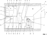
- FIG. 1 a front view of a plumbing installation system 1 is shown.
- the sanitary installation system 1 is arranged in a building G and is permanently connected to the building G.
- the sanitary installation system 1 comprises a mounting structure 2, at least one cladding element 3 that conceals the mounting structure 2 and at least one water-bearing sanitary element 4.
- the water-bearing sanitary element 4 is shown here in the form of a cistern, which is provided with another lying in front of the cladding element 3 outside the cavity 5 Sanitary element, such as a toilet bowl can be connected.
- the sanitary installation system 1 further comprises at least one sound absorption element 6.
- the mounting structure 2 and the at least one cladding element 3 define a cavity 5, the sound absorption element 6 being arranged in the cavity 5.
- the at least one water-bearing sanitary element 4 can be at least partially in the cavity 5 be arranged.
- the mounting structure 2 is a mounting frame and a plurality of sound absorption elements 6 are arranged in the cavity. Corresponding sound absorption elements 6 are provided in all areas.
- the assembly structure 2 is arranged in front of a wall W of the building G.
- the mounting structure 2 comprises receiving structures 21 for a toilet, a washbasin and a shower.
- the cladding element 3 is only shown schematically here and, for the sake of clarity, extends only over a partial area of the mounting structure 2.
- the at least one sound absorption element 6 is fastened to the mounting structure 2 with at least one fastening element 11.
- the fastening element 11 can be designed differently. In the figures, a fastening element 11 is shown, with which the sound absorption element 6 is suspended freely, in particular freely swinging, on the mounting structure 2 in the holding frame 5. The sound absorption element 6 can therefore be suspended in the cavity 5 via the fastening element 11 and is mounted in a freely oscillating manner. This means that the sound absorption element 6 is connected exclusively to the fastening element 11 with the mounting structure 2 and could execute an oscillating movement about the fastening element 11. This freely suspended mounting has the advantage that sound waves can be correspondingly well absorbed.
- the fastening element 11 is arranged at the upper end 7 of the sound absorption element 6.
- the sound absorption element 6 could also be mounted in such a way that it is connected to the mounting structure 2 at the top and bottom. In this variant, the sound absorption element 6 would no longer be directly free-swinging.
- the sound absorption element 6 is fastened to a strut 19 of the mounting structure 2 that runs in the horizontal H.
- the sound absorption element 6 hangs down in the vertical direction.
- the strut bears the reference number 19.
- the strut 19 can be part of a cross member 20 of the mounting structure or the strut 19 can be part of a bearing element 18, which can be connected to a cross member 20 of the mounting structure.
- the sound absorption element 6 would then be firmly attached to a strut running in the horizontal H and / or to a strut of the mounting structure 2 running in the vertical.
- the sound absorption element 6 is designed as a determined or solid or dimensionally stable body.
- the sound absorption element 6 has a front surface 8, a rear surface 9 and four side surfaces 10 which connect the rear surface 9 to the front surface 8.
- the rear surface 9 and the front surface 8 run parallel to one another.
- the sound absorption element 6 is designed as a cuboid. Other shapes are also possible.
- the sound absorption element 6 could also be designed as a cylinder with a center axis extending vertically.
- the surfaces 8, 9, 10 are essentially flat or planar.
- the sound absorption element 6 has a significantly greater extent in the vertical direction V than in the horizontal direction H.
- the extent in the vertical direction V is preferably a factor of 5 to 20 greater than the extent in the horizontal direction H. This makes a comparative Slender body created, which has good advantages for sound absorption. This is particularly the case with the typically tight space conditions for assembly.
- FIG. 3 A preferred mounting of the sound absorption element 6 is shown.
- the sound absorption element 6 is mounted with the fastening element 11 on a strut 19 running in the horizontal.
- the strut 19 is on a load bearing Traverse 20 of the mounting structure 2 attached.
- the strut 19 protrudes into a profile groove 17 on the cross member 20 and is fixed there accordingly. For example, using a rotary movement.
- the strut 19 has a specific bearing area 22 on which the fastening element 11 can then be suspended.
- the bearing area 22 is formed by two surfaces and is preferably located at the lowest point of the two surfaces.
- an upper fastening element 11 and a lower fastening element 12 are arranged in each case.
- This arrangement has the advantage that a further sound absorption element 6 can be suspended or fastened on the lower fastening element 12.
- the fastening element 11 of the sound absorption element 6 then engages in the lower fastening element 12 of the upper sound absorption element 6. It is on the two sound absorption elements 6 in the Figure 1 referenced, which are arranged on the far left.
- each of the two fastening elements 11, 12 comprises a holding section 13 with which the fastening element 11, 12 protrudes into the sound absorption element 6.
- the holding section 13 has barbs 14 which are arranged in such a way that the barbs provide resistance in the event of a pull-out force F on the fastening element 11, 12. This means that the fastening element 11, 12 cannot be pulled out of the sound absorption element 6, or only with great effort, due to the barbs 14.
- the barbs are part of a dowel element 23 into which the actual fastening element 11, 12 protrudes.
- the barbs 14 can, however, also be an integral part of the fastening element 11, 12.
- the fastening elements 11, 12 also have a hook section 15.
- the hook section 15 comprises a hook 16 with which the fastening elements 11, 12 can be connected to the strut 19 as described above.
- the sound absorption element 6 preferably has a length-related flow resistance of> 5 kPa * s / m2.
- the sound absorption element 6 is preferably made from polyethylene terephthalate, in particular from recycled polyethylene terephthalate. Other materials are also conceivable.
- the sound absorption element 6 preferably has a layer structure, the layers all being oriented in the same direction and being connected to one another.
- the layer plane is oriented essentially in the vertical plane, which is advantageous for the sound absorption properties of the sound absorption element 6.
- the sound absorption elements 6 fill the cavity 5 only partially, that is, not completely.
- the sound absorption element 6 particularly preferably fills the cavity 5 up to a maximum of 50 percent by volume.
- any gaps between individual sound absorption elements 6 can have a positive effect on sound absorption.
- a method for assembling a sanitary installation system is characterized in that in a first step the assembly structure is arranged, that in a further step the connection elements are assembled, that in a further step the at least one sound absorption element 6 is assembled and that in a further step the at least one cladding element 3.
- the at least one sanitary element is installed, depending on the position inside the cavity or outside the cavity, between or after the steps mentioned.
Landscapes
- Engineering & Computer Science (AREA)
- General Engineering & Computer Science (AREA)
- Physics & Mathematics (AREA)
- Mechanical Engineering (AREA)
- Acoustics & Sound (AREA)
- Public Health (AREA)
- Health & Medical Sciences (AREA)
- Life Sciences & Earth Sciences (AREA)
- Hydrology & Water Resources (AREA)
- Architecture (AREA)
- Water Supply & Treatment (AREA)
- Electromagnetism (AREA)
- Civil Engineering (AREA)
- Structural Engineering (AREA)
- Environmental & Geological Engineering (AREA)
- Building Environments (AREA)
Abstract
Description
- Die vorliegende Erfindung betrifft ein Sanitärinstallationssystem mit einem Schallabsorptionselement nach dem Oberbegriff von Anspruch 1.
- Aus dem Stand der Technik sind Sanitärinstallationssysteme bekannt geworden. Solche Sanitärinstallationssysteme umfassen typischerweise eine Montagestruktur, welche fest mit dem Gebäude verbunden wird. An der Montagestruktur werden dann die Sanitärartikel, wie eine Toilettenschüssel, ein Waschtisch, etc., befestigt oder angelegt und es werden zudem die Frischwasserleitungen und die Abwasserleitungen durch die Montagestruktur geführt. Die Montagestruktur wird durch eine Vorwandung verkleidet, wodurch ein Hohlraum bereitgestellt wird.
- In der Praxis ist man aus Gründen des Schallschutzes dazu übergegangen, diesen Hohlraum mit Mineralwolle oder Flockenmaterial auszufüllen. Das Ausfüllen des Hohlraums verringert den Wiederhall von Geräuschen durch die Wasserzufuhr bzw. Wasserabfuhr zu den Sanitärartikeln oder von Geräuschen durch fallende WC-Deckel, erhöht aber die Montagezeit deutlich. Darüber hinaus ergehen technische Nachteile, beispielsweise, wenn zuviel Mineralwolle oder Flockenmaterial in den Hohlraum gepresst wird.
- Ausgehend von diesem Stand der Technik liegt der Erfindung eine Aufgabe zugrunde, ein Sanitärinstallationssystem anzugeben, welches die Nachteile des Standes der Technik überwindet. Insbesondere soll das Sanitärinstallationssystem einfach und reproduzierbar montierbar sein.
- Diese Aufgabe löst der Gegenstand von Anspruch 1. Demgemäss umfasst ein Sanitärinstallationssystem eine fest mit einem Gebäude verbindbare Montagestruktur, mindestens ein die Montagestruktur verdeckendes Verkleidungselement, und mindestens ein wasserführendes Sanitärelement. Die Montagestruktur und das mindestens eine Verkleidungselement definieren einen Hohlraum. Mindestens eines der wasserführenden Sanitärelemente ist im Hohlraum angeordnet. Weiter ist im Hohlraum mindestens ein Schallabsorptionselement angeordnet. Das mindestens eine Schallabsorptionselement ist mit mindestens einem Befestigungselement an der Montagestruktur befestigt.
- Durch die Befestigung des Schallabsorptionselementes mit dem mindestens einen Befestigungselement an der Montagestruktur kann eine determinierte Befestigung geschaffen werden. Dem Installateur wird demnach eine Montagehilfe an die Hand gegeben, was den Vorteil einer einfachen Montage ergibt. Darüber hinaus lassen sich die Schallabsorptionselemente bei grösseren Anlagen reproduzierbar montieren, was den Vorteil einer bestimmbaren Schalldämmung hat.
- Unter der Ausdrucksweise "Anschlusselemente" werden Elemente verstanden, welche typischerweise in derartigen Strukturen eingesetzt werden. Beispielhaft werden Spülkästen. Wasserleitungen, Abwasserleitungen etc. genannt.
- Neben dem im Hohlraum liegenden wasserführenden Sanitärelement können weitere ausserhalb des Hohlraums liegende wasserführende Sanitärelemente angeordnet sein. Ein Beispiel für ein im Hohlraum liegendes wasserführendes Sanitärelement ist eine Fallleitung. Wasserführende Sanitärelemente, welche ausserhalb des Hohlraums vor dem Verkleidungselement liegen sind beispielsweise Toilettenschüsseln, Urinale, Bidet, Waschtische, Duschen, etc. mit zugehörigen wiederum im Hohlraum liegenden Sanitärelementen, wie Spülkästen, Wasserleitungen, Abwasserleitungen, etc..
- In einer ersten bevorzugten Ausführungsform ist das Schallabsorptionselement mit dem mindestens einen Befestigungselement an einem oberen Ende des Schallabsorptionselements freihängend und insbesondere freischwingend an der Montagestruktur im Hohlraum aufgehängt.
- Unter der Ausdrucksweise "freihänged" wird verstanden, dass das Schallabsorptionselement an mindestens einer Stelle aufgehängt ist und keinen weiteren Kontakt mit der Montagestruktur aufweist. Durch die freihängende Aufhängung ergeht eine einfache Montage sowie eine verbesserte Schalldämmung.
- Vorzugsweise ist das Schallabsorptionselement an mindestens einer Stelle oder ausschliesslich genau einer Stelle aufgehängt bzw. befestigt. Vorzugsweise ist die Befestigungsstelle in Einbaulage am oberen Ende des Schallabsorptionselements angeordnet. In einer anderen Variante könnte das Schallabsorptionselement in Einbaulage gesehen nicht nur oben, sondern auch unten mit der Montagestruktur verbunden werden.
- Vorzugsweise ist das Schallabsorptionselement an einer in der Horizontalen verlaufenden Strebe der Montagestruktur befestigt ist und hängt in vertikaler Richtung nach unten. Die Strebe kann verschiedenartig ausgebildet sein. In einer ersten Variante ist die Strebe eine lasttragende Traverse der Montagestruktur. Unter einer lasttragenden Traverse wird ein Profilstab verstanden, an welcher ein Sanitärelement befestigt werden kann. In einer zweiten Variante ist die Strebe Teil eines Lagerelements, welches in eine Profilnut einer Traverse der Montagestruktur einrastbar ist.
- In einer zweiten Ausführungsform ist das Schallabsorptionselement mit dem mindestens einen Befestigungselement fest mit der Montagestruktur verbunden. In dieser Ausführungsform wird das Schallabsorptionselement mechanisch fest mit der Montagestruktur verbunden. Das Befestigungselement kann beispielsweise ein Kabelbinder, eine Klammer, ein Klettverschluss, ein Klebeband oder ein am Schallabsorberelement fest befestigtes Magnet sein.
- Vorzugsweise ist das Schallabsorptionselement nach der zweiten Ausführungsform an mindestens einer in der Horizontalen verlaufenden Strebe und/oder an mindestens einer in der Vertikalen verlaufenden Strebe der Montagestruktur befestigt. Besonders bevorzugt wird das Schallabsoprtionselement zwischen zwei in die gleiche Richtung verlaufende Streben angeordnet und wird über Befestigungselemente mit den beiden Streben verbunden.
- In der Folge werden weitere Eigenschaften des Sanitärinstallationssystems erläutert, wobei die Erläuterung für beide Ausführungsformen anwendbar sind.
- Vorzugsweise ist das Schallabsorptionselement als determinierter bzw. fester bzw. formstabiler Körper ausgebildet ist. Eine derartige Ausbildung hat den Vorteil, dass dem Installateur ein Schallabsorptionselement mit definierter Ausbildung bereitgestellt wird, wodurch die Handhabung des Schallabsorptionselements einfacher wird.
- Besonders bevorzugt weist das Schallabsorptionselement eine Frontfläche, eine Rückfläche und mindestens eine Seitenfläche auf, wobei die Rückfläche parallel und beabstandet zur Frontfläche verläuft, und wobei die Rückfläche und die Frontfläche über die Seitenfläche miteinander verbunden sind.
- Besonders bevorzugt ist das Schallabsorptionselement als Quader ausgebildet ist. Das Schallabsorptionselement kann aber auch als Zylinder ausgebildet sein.
- Vorzugsweise weist das Schallabsorptionselement in Einbaulage in vertikaler Richtung eine wesentlich grössere Ausdehnung auf als in horizontaler Richtung. Hierdurch ergeht der Vorteil, dass die üblicherweise zur Verfügung stehenden Platzverhältnisse gut ausgenützt werden können.
- Besonders bevorzugt ist die Ausdehnung in vertikaler Richtung um einen Faktor 5 bis 20 grösser ist als die Ausdehnung in horizontaler Richtung.
- Vorzugsweise weist das Schallabsorptionselement eine Länge von 80 bis 120 Zentimeter, eine Breite von 10 bis 20 Zentimetern und eine Dicke von 2 bis 10 Zentimetern, insbesondere von 3 bis 8 Zentimetern, auf.
- Vorzugsweise liegt das Schallabsorptionselement derart im Hohlraum, dass sich dieses nur über einen Teilbereich der Höhe erstreckt und dass dieses beabstandet zum Boden des Gebäudes liegt.
- Vorzugsweise sind bei mehreren Schallabsorptionselementen die Schallabsorptionselemente im Wesentlichen gleichmässig im Hohlraum verteilt. Hierdurch kann eine gute Schaldämmung erreicht werden.
- Vorzugsweise nimmt die Projektion des Schallabsorptionselements in einer Projektionsebene der Frontseite der Montagestruktur zwischen 15% und 45% der gesamten Projektionsfläche der Frontseite ein. Die Projektionsebene ist eine Ebene die rechtwinklig zur Flächennormalen auf die Frontseite des Verkleidungselementes gesehen.
- Vorzugsweise füllt das Schallabsorptionselement den Hohlraum nur teilweise bzw. nicht vollständig aus. Besonders bevorzugt füllt das Schallabsorptionselement den Hohlraum bis maximal 50 Volumenprozente aus.
- Vorzugsweise weist das Schallabsorptionselement einen längenbezogenen Strömungswiderstand von grösser als 5 kPa*s /m2 auf. Unter kPa*s/m2 wird die Masseinheit Kilo-Pascal (Druck) mal Sekunde (Zeit) geteilt durch Quadratmeter (Fläche) verstanden.
- Vorzugsweise ist das Schallabsorptionselement aus Polyethylenterephthalat, insbesondere aus rezykliertiem Polyethylenterephthalat, hergestellt. Vorzugsweise sind es Schallabsorptionselemente, welche aus Fasern bestehen und mehrlagig übereinandergeschichtet aufgebaut sind. Es können Chemiefasern aus synthetischen Polymeren (beispielsweise Polyestervliesstoff), pflanzliche Fasern (beispielsweise Baumwollvliesstoff), chemisch anorganische Fasern (beispielsweise Glasfaservliesstoffe), tierische Fasern (beispielsweise Wollfaservliesstoff), Chemiefasern aus natürlichen Polymeren pflanzlichen beziehungsweise cellulosischen Ursprungs (beispielsweise Viskosefaservliesstoff) oder ferner aus Chemiefasern aus Nichtpolymeren (beispielsweise Edelstahlfaservliesstoff). Alternativ wären auch geschäumte Werkstoffe (beispielsweise Polyurethan oder Polystyrol) oder Kombinationen aus geschäumten Werkstoffen und Faserwerkstoffen möglich.
- Vorzugsweise ist das Schallabsorptionselement aus einem feuerfesten Material.
- Besonders bevorzugt weist das Schallabsorptionselement, insbesondere, wenn es aus den oben genannten Fasern ist, eine Schichtstruktur auf, wobei die Schichten alle in die gleiche Richtung orientiert sind und miteinander verbunden sind. Das Schallabsorptionselement kann auch als Akustikvlies bezeichnet werden.
- Vorzugsweise ist das Befestigungselement ein oberes Befestigungselement, mit welchem das Schallabsorptionselement an der Montagestruktur aufgehängt bzw. befestigt werden kann.
- Vorzugsweise weist das Schallabsorptionselement weiter ein unteres Befestigungselement auf, das derart angeordnet ist, dass am unteren Befestigungselement ein weiteres Schallabsorptionselement aufgehängt bzw. befestigt werden kann.
- Vorzugsweise umfassen das obere Befestigungselement und/oder das untere Befestigungselement einen Halteabschnitt, mit welchem das Befestigungselement in das Schallabsorptionselement einragt, wobei der Halteabschnitt vorzugsweise Widerhaken aufweist, welche derart angeordnet sind, dass die Widerhaken einen Widerstand bei einer Auszugskraft auf das Befestigungselement bereitstellen.
- Die Widerhaken können direkt am Befestigungselement angeformt sein. Die Widerhaken können aber auch Teil eines Dübelelementes sein, mit welchem das Befestigungselement verbunden werden kann.
- Besonders bevorzugt weist das Befestigungselement einen Hakenabschnitt mit einem Haken auf, an welchem das Befestigungselement mit der Montagestruktur verbunden werden kann. Mit dem Haken kann das Befestigungselement sehr einfach mit der Montagestruktur über eine Einhängbewegung eingehängt werden.
- Ein Verfahren zur Montage eines Sanitärinstallationssystem nach obiger Beschreibung ist dadurch charakterisiert, dass in einem ersten Schritt die Montagestruktur angeordnet wird, dass in einem weiteren Schritt die Anschlusselemente montiert werden, dass in einem weiteren Schritt das mindestens eine Schallabsorptionselement montiert wird, und dass in einem weiteren Schritt das mindestens eine Verkleidungselement montiert wird, wobei zwischen oder nach den genannten Schritten, das mindestens eine wasserführende Sanitärelement montiert wird.
- Weitere Ausführungsformen sind in den abhängigen Ansprüchen angegeben.
- Bevorzugte Ausführungsformen der Erfindung werden im Folgenden anhand der Zeichnungen beschrieben, die lediglich zur Erläuterung dienen und nicht einschränkend auszulegen sind. In den Zeichnungen zeigen:
- Fig. 1
- eine Frontansicht eines Sanitärinstallationssystem nach einer Ausführungsform der vorliegenden Erfindung;
- Fig. 2
- eine perspektivische Ansicht eines Schallabsorptionselements, das im Sanitärinstallationssystem nach der
Figur 1 eingesetzt ist; - Fig. 3
- eine Detailansicht der
Figur 2 ; und - Fig. 4
- eine Schnittdarstellung im Bereich der Aufhängung des Schallabsorptionselements nach der
Figur 1 . - In der
Figur 1 wird eine Frontansicht eines Sanitärinstallationssystems 1 gezeigt. Das Sanitärinstallationssystems 1 ist in einem Gebäude G angeordnet und wird mit dem Gebäude G fest verbunden. - Das Sanitärinstallationssystem 1 umfasst eine Montagestruktur 2, mindestens ein die Montagestruktur 2 verdeckendes Verkleidungselement 3 und mindestens ein wasserführendes Sanitärelement 4. Das wasserführende Sanitärelement 4 wird hier in der Form eines Spülkastens gezeigt, welcher mit einem vor dem Verkleidungselement 3, ausserhalb des Hohlraums 5 liegenden weiteren Sanitärelement, wie beispielsweise einer Toilettenschüssel verbunden werden kann. Weiter umfasst das Sanitärinstallationssystems 1 mindestens ein Schallabsorptionselement 6. Die Montagestruktur 2 und das mindestens eine Verkleidungselement 3 definieren einen Hohlraum 5, wobei im Hohlraum 5 das Schallabsorptionselement 6 angeordnet ist. Weiter kann, wie oben beschrieben, das mindestens eine wasserführende Sanitärelement 4 mindestens teilweise im Hohlraum 5 angeordnet sein. In der gezeigten Ausführungsform ist die Montagestruktur 2 ein Montagerahmen und es sind mehrere Schallabsorptionselemente 6 im Hohlraum angeordnet. Dabei sind in allen Bereichen entsprechende Schallabsorptionselemente 6 vorhanden. Die Montagestruktur 2 wird dabei vor einer Wand W des Gebäudes G angeordnet. In der gezeigten Ausführungsform umfasst die Montagestruktur 2 Aufnahmestrukturen 21 für eine Toilette, einen Waschtisch und eine Dusche.
- Das Verkleidungselement 3 ist hier nur schematisch dargestellt und erstreckt sich in der Darstellung der Übersichtlichkeit halber nur über einen Teilbereich der Montagestruktur 2. Das Verkleidungselement 3 verdeckt aber die Montagestruktur 2 im Wesentlichen vollständig.
- Das mindestens eine Schallabsorptionselement 6 ist mit jeweils mindestens einem Befestigungselement 11 an der Montagestruktur 2 befestigt. Das Befestigungselement 11 kann unterschiedlich ausgebildet sein. In den Figuren wird ein Befestigungselement 11 gezeigt, mit welchem das Schallabsorptionselement 6 freihängend, insbesondere freischwingend, an der Montagestruktur 2 im Halterahmen 5 aufgehängt ist. Über das Befestigungselement 11 kann also das Schallabsorptionselement 6 jeweils in den Hohlraum 5 eingehängt werden und ist freischwingend gelagert. Das heisst, das Schallabsorptionselement 6 steht ausschliesslich mit dem Befestigungselement 11 mit der Montagestruktur 2 in Verbindung und könnte eine Schwingbewegung um das Befestigungselement 11 ausführen. Durch diese freihängende Lagerung ergeht der Vorteil, dass Schallwellen entsprechend gut absorbiert werden können. Das Befestigungselement 11 ist am oberen Ende 7 des Schallabsorptionselements 6 angeordnet.
- In anderen Varianten könnte das Schallabsorptionselement 6 aber auch derart montiert sein, dass es oben und unten mit der Montagestruktur 2 in Verbindung steht. In dieser Variante wäre das Schallabsorptionselement 6 nicht mehr direkt freischwingend.
- Das Schallabsorptionselement 6 ist in der gezeigten Ausführungsform an einer in der Horizontalen H verlaufenden Strebe 19 der Montagestruktur 2 befestigt. Dabei hängt das Schallabsorptionselement 6 in vertikaler Richtung nach unten. Die Strebe trägt das Bezugszeichen 19. Die Strebe 19 kann Teil einer Traverse 20 der Montagestruktur sein oder die Strebe 19 kann Teil eines Lagerelementes 18 sein, welches mit einer Traverse 20 der Montagestruktur verbunden werden kann.
- In anderen, in den Figuren nicht gezeigten Ausführungsformen, wäre es auch denkbar, das Schallabsorptionselement 6 fest mit einem Befestigungselement 11 mit der Montagestruktur zu verbinden. Beispielsweise wäre das Schallabsorptionselement 6 dann an eine in der Horizontalen H verlaufenden Strebe und/oder an einer in der Vertikalen verlaufenden Strebe der Montagestruktur 2 fest befestigt.
- In der
Figur 2 wird eine perspektivische Ansicht des Schallabsorptionselementes 6 gezeigt. Das Schallabsorptionselement 6 ist als determinierter bzw. fester bzw. formstabiler Körper ausgebildet. In der gezeigten Ausführungsform weist das Schallabsorptionselementes 6 eine Frontfläche 8, eine Rückfläche 9 und vier Seitenflächen 10 auf, welche die Rückfläche 9 mit der Frontfläche 8 verbinden. Die Rückfläche 9 und die Frontfläche 8 verlaufen dabei parallel zueinander. Das Schallabsorptionselementes 6 ist als Quader ausgebildet. Andere Formen sind ebenfalls denkbar. Beispielsweise könnte das Schallabsorptionselement 6 auch als Zylinder mit einer sich in der Vertikalen erstreckenden Mittelachse ausgebildet sein. - Vorzugsweise sind die Flächen 8, 9, 10 im Wesentlichen flach oder eben ausgebildet. Es wäre aber auch denkbar, einige oder alle der Flächen 8, 9, 10 mit einer Oberflächenstruktur zu versehen. Beispielsweise mit einer Vielzahl von abstehenden Wellen, Pyramiden, Noppen, etc. Hierdurch können die Schallabsorptionseigenschaften noch verbessert werden.
- Das Schallabsorptionselementes 6 weist in der gezeigten Ausführungsform in vertikaler Richtung V eine wesentlich grössere Ausdehnung auf als in horizontaler Richtung H. Die Ausdehnung in vertikaler Richtung V ist vorzugsweise um einen Faktor 5 bis 20 grösser als die Ausdehnung in horizontaler Richtung H. Hierdurch wird ein vergleichsweise schlanker Körper geschaffen, welcher für die Schallabsorption gute Vorteile aufweist. Dies gerade bei den für die Montage typischerweise engen Platzverhältnisse.
- In der
Figur 3 wird eine bevorzugte Lagerung des Schallabsorptionselementes 6 gezeigt. Hier ist das Schallabsorptionselementes 6 mit dem Befestigungselement 11 an einer in der Horizontalen verlaufenden Strebe 19 gelagert. Die Strebe 19 ist dabei an einer lasttragenden Traverse 20 der Montagestruktur 2 angebracht. Vorzugsweise ragt die Strebe 19 in eine Profilnut 17 an der Traverse 20 ein und wird dort entsprechend festgesetzt. Beispielsweise über eine Drehbewegung. Die Strebe 19 weist in der gezeigten Ausführungsform einen bestimmten Lagerbereich 22 auf, an welchem dann das Befestigungselement 11 eingehängt werden kann. Der Lagerbereich 22 wird durch zwei Flächen gebildet und liegt bevorzugt am tiefsten Punkt der beiden Flächen. - In den gezeigten Ausführungsformen sind jeweils ein oberes Befestigungselement 11 und ein unteres Befestigungselement 12 angeordnet. Diese Anordnung hat den Vorteil, dass am unteren Befestigungselement 12 ein weiteres Schallabsorptionselementes 6 aufgehängt bzw. befestigt werden kann. Dabei greift dann das Befestigungselement 11 des Schallabsorptionselementes 6 in das untere Befestigungselement 12 des oberen Schallabsorptionselementes 6 ein. Es wird dabei auf die beiden Schallabsorptionselemente 6 in der
Figur 1 verwiesen, welche ganz links angeordnet sind. - Unter Bezugnahme auf die
Figur 4 wird eine beispielhafte Verbindung der Befestigungselemente 11, 12 mit dem Schallabsorptionselement 6 gezeigt. Die diesbezüglichen Ausführungen treffen sowohl auf die Anordnung von einem Befestigungselement als auch auf die Anordnung von mehreren Befestigungselementen zu. Jedes der beiden Befestigungselemente 11, 12 umfasst in der gezeigten Ausführungsform jeweils einen Halteabschnitt 13, mit welchem das Befestigungselement 11, 12 in das Schallabsorptionselementes 6 einragt. Der Halteabschnitt 13 weist in der gezeigten Ausführungsform Widerhaken 14 auf, welche derart angeordnet sind, dass die Widerhaken einen Widerstand bei einer Auszugskraft F auf das Befestigungselement 11, 12 bereitstellen. Das heisst, dass das Befestigungselement 11, 12 aufgrund der Widerhaken 14 nicht oder nur mit grossem Kraftaufwand aus dem Schallabsorptionselementes 6 herausziehbar ist. In der gezeigten Ausführungsform sind die Widerhaken Teil eines Dübelelementes 23, in welches das eigentliche Befestigungselement 11, 12 einragt. Die Widerhaken 14 können aber auch integraler Bestandteil des Befestigungselementes 11, 12 sein. Weiter weisen die Befestigungselemente 11, 12 einen Hakenabschnitt 15 auf. Der Hakenabschnitt 15 umfasst einen Haken 16, mit welchem die Befestigungselemente 11, 12 wie oben beschrieben mit der Strebe 19 verbunden werden kann. - Das Schallabsorptionselementes 6 weist vorzugsweise einen längenbezogenen Strömungswiderstand von >5kPa*s/m2 auf.
- Weiter ist das Schallabsorptionselementes 6 vorzugsweise aus Polyethylenterephthalat, insbesondere aus rezykliertiem Polyethylenterephthalat ausgebildet. Andere Materialien sind auch denkbar.
- Das Schallabsorptionselementes 6 weist bevorzugt eine Schichtstruktur auf, wobei die Schichten alle in die gleiche Richtung orientiert sind und miteinander verbunden sind. In der gezeigten Ausführungsform ist die Schichtebene im Wesentlichen in vertikaler Ebene orientiert, was für die Schallabsorptionseigenschaften des Schallabsorptionselementes 6 von Vorteil ist.
- Wie von der
Figur 1 gezeigt, füllen die Schallabsorptionselemente 6 den Hohlraum 5 nur teilweise, das heisst nicht vollständig, aus. Besonders bevorzugt füllt das Schallabsorptionselementes 6 den Hohlraum 5 bis maximal 50 Volumenprozenten aus. - Die Projektion des Schallabsorptionselements 6 in einer Projektionsebene der Montagestruktur gesehen nimmer vorzugsweise zwischen 15% und 45% der gesamten Projektionsfläche der Frontseite ein.
- Bei mehreren Schallabsorptionselementen 6 ist es vorteilhaft, die Schallabsorptionselementes 6 im Wesentlichen gleichmässig im Hohlraum 5 zu verteilen. Allfällige Lücken zwischen einzelnen Schallabsorptionselementen 6 können sich positiv auf die Schallabsorption auswirken.
- Ein Verfahren zur Montage eines Sanitärinstallationssystem nach obiger Beschreibung ist dadurch charakterisiert, dass in einem ersten Schritt die Montagestruktur angeordnet wird, dass in einem weiteren Schritt die Anschlusselemente montiert werden, dass in einem weiteren Schritt das mindestens eine Schallabsorptionselement 6 montiert wird, und dass in einem weiteren Schritt das mindestens eine Verkleidungselement 3. Das mindestens eine Sanitärelement wird, je nach Lage im Inneren des Hohlraums oder ausserhalb des Hohlraums, zwischen oder nach den genannten Schritten montiert.
BEZUGSZEICHENLISTE 1 Sanitärinstallationssystem 17 Profilnut 2 Montagestruktur 18 Lagerelement 3 Verkleidungselement 19 Strebe 4 Anschlusselement 20 Traverse 5 Hohlraum 21 Aufnahmestrukturen 6 Schallabsorptionselement 22 Lagerbereich 7 oberes Ende 23 Dübelelement 8 Frontfläche F Auszugskraft 9 Rückfläche G Gebäude 10 Seitenfläche V vertikale Richtung 11 Befestigungselement H horizontale Richtung 12 unteres Befestigungselement W Wand 13 Halteabschnitt 14 Widerhaken 15 Hakenabschnitt 16 Haken
Claims (17)
- Sanitärinstallationssystem (1) umfassend
eine fest mit einem Gebäude (G) verbindbare Montagestruktur (2),
mindestens ein die Montagestruktur (2) verdeckendes Verkleidungselement (3), und mindestens ein wasserführendes Sanitärelement (4),
wobei die Montagestruktur (2) und das mindestens eine Verkleidungselement (3), einen Hohlraum (5) definieren, wobei mindestens eines der wasserführenden Sanitärelemente (4) im Hohlraum (5) angeordnet ist und wobei im Hohlraum (5) mindestens ein Schallabsorptionselement (6) angeordnet ist, dadurch gekennzeichnet,
dass das mindestens eine Schallabsorptionselement (6) mit mindestens einem Befestigungselement (11) an der Montagestruktur (2) befestigt ist. - Sanitärinstallationssystem (1) nach Anspruch 1, dadurch gekennzeichnet, dass das Schallabsorptionselement (6) mit dem mindestens einen Befestigungselement (11) an einem oberen Ende (7) des Schallabsorptionselements (6) freihängend und insbesondere freischwingend an der Montagestruktur (2) im Hohlraum (5) aufgehängt ist.
- Sanitärinstallationssystem (1) nach Anspruch 2, dadurch gekennzeichnet, dass das Schallabsorptionselement (6) an mindestens einer Stelle oder ausschliesslich genau einer Stelle aufgehängt bzw. befestigt ist.
- Sanitärinstallationssystem (1) nach einem der vorhergehenden Ansprüche, dadurch gekennzeichnet, dass das Schallabsorptionselement (6) an mindestens einer in der Horizontalen (H) verlaufenden Strebe (19) der Montagestruktur (2) befestigt ist und in vertikaler Richtung nach unten hängt, wobei die Strebe (19) eine lasttragende Traverse (20) der Montagestruktur (2) ist; oder wobei die Strebe (19) Teil eines Lagerelements (18) ist, welches in eine Profilnut (17) einer Traverse (2) der Montagestruktur einrastbar ist.
- Sanitärinstallationssystem nach Anspruch 1, dadurch gekennzeichnet, dass das Schallabsorptionselement (6) mit dem mindestens einen Befestigungselement (11) fest mit der Montagestruktur (2) verbunden ist.
- Sanitärinstallationssystem nach Anspruch 5, dadurch gekennzeichnet, dass das Schallabsorptionselement (6) an mindestens einer in der Horizontalen (H) verlaufenden Strebe und/oder an mindestens einer in der Vertikalen verlaufenden Strebe der Montagestruktur (2) befestigt ist.
- Sanitärinstallationssystem (1) nach einem der vorhergehenden Ansprüche, dadurch gekennzeichnet, dass das Schallabsorptionselement (6) als determinierter bzw. fester bzw. formstabiler Körper ausgebildet ist und/oder dass das Schallabsorptionselement (6) eine Frontfläche (8), eine Rückfläche (9) und mindestens eine Seitenfläche (10) aufweist, wobei die Rückfläche (9) parallel und beabstandet zur Frontfläche (8) verläuft, und wobei die Rückfläche (9) und die Frontfläche (8) über die Seitenfläche (10) miteinander verbunden sind.
- Sanitärinstallationssystem (1) nach einem der vorhergehenden Ansprüche, dadurch gekennzeichnet, dass das Schallabsorptionselement (6) in Einbaulage in vertikaler Richtung (V) eine wesentlich grössere Ausdehnung aufweist als in horizontaler Richtung (H), wobei die Ausdehnung in vertikaler Richtung (V) vorzugsweise um einen Faktor 5 bis 20 grösser ist als die Ausdehnung in horizontaler Richtung (H).
- Sanitärinstallationssystem (1) nach einem der vorhergehenden Ansprüche, dadurch gekennzeichnet, dass das Schallabsorptionselement (6) derart im Hohlraum (5) liegt, dass sich dieses nur über einen Teilbereich der Höhe erstreckt und dass dieses beabstandet zum Boden (B) des Gebäudes (G) liegt.
- Sanitärinstallationssystem (1) nach einem der vorhergehenden Ansprüche, dadurch gekennzeichnet, dass bei mehreren Schallabsorptionselementen (6) die Schallabsorptionselemente (6) im Wesentlichen gleichmässig im Hohlraum (5) verteilt sind und/oder dass die Projektion des Schallabsorptionselements in einer Projektionsebene der Montagestruktur zwischen 15% und 45% der gesamten Projektionsfläche der Frontseite einnimmt.
- Sanitärinstallationssystem (1) nach einem der vorhergehenden Ansprüche, dadurch gekennzeichnet, dass das Schallabsorptionselement (6) den Hohlraum (5) nur teilweise bzw. nicht vollständig ausfüllt, insbesondere dass das Schallabsorptionselement (6) den Hohlraum (5) bis maximal 50 Volumenprozente ausfüllt.
- Sanitärinstallationssystem (1) nach einem der vorhergehenden Ansprüche, dadurch gekennzeichnet, dass das Schallabsorptionselement (6) einen längenbezogenen Strömungswiderstand von grösser als 5 kPa*s/m2 aufweist und/oder dass das Schallabsorptionselement (6) aus einem feuerfesten Material ist.
- Sanitärinstallationssystem (1) nach einem der vorhergehenden Ansprüche, dadurch gekennzeichnet, dass das Schallabsorptionselement (6) eine Schichtstruktur aufweist, wobei die Schichten alle in die gleiche Richtung orientiert sind und miteinander verbunden sind.
- Sanitärinstallationssystem (1) nach einem der vorhergehenden Ansprüche, dadurch gekennzeichnet, dass Befestigungselement (11) ein oberes Befestigungselement (11) ist, mit welchem das Schallabsorptionselement (6) an der Montagestruktur (2) aufgehängt bzw. befestigt werden kann und/oder dass das Schallabsorptionselement (6) ein unteres Befestigungselement (12) aufweist, das derart angeordnet ist, dass am unteren Befestigungselement (12) ein weiteres Schallabsorptionselement (6) aufgehängt bzw. befestigt werden kann.
- Sanitärinstallationssystem (1) nach einem der vorhergehenden Ansprüche 13 oder 14, dadurch gekennzeichnet, dass das obere Befestigungselement (11) bzw. das untere Befestigungselement (12) einen Halteabschnitt (13) umfasst, mit welchem das Befestigungselement (11, 12) in das Schallabsorptionselement (6) einragt, wobei der Halteabschnitt (13) vorzugsweise Widerhaken (14) aufweist, welche derart angeordnet sind, dass die Widerhaken (14) einen Widerstand bei einer Auszugskraft (F) auf das Befestigungselement (11, 12) bereitstellen.
- Sanitärinstallationssystem (1) nach einem der vorhergehenden Ansprüche 14 oder 15, dadurch gekennzeichnet, dass das Befestigungselement (11, 12) einen Hakenabschnitt (15) mit einem Haken (16) aufweist, an welchem das Befestigungselement (11, 12) mit der Montagestruktur verbunden werden kann.
- Verfahren zur Montage eines Sanitärinstallationssystem nach einem der vorhergehenden Ansprüche, dadurch gekennzeichnet, dass in einem ersten Schritt die Montagestruktur (2) angeordnet wird, dass in einem weiteren Schritt die Anschlusselemente (4) montiert werden, dass in einem weiteren Schritt das mindestens eine Schallabsorptionselement (6) montiert wird, und dass in einem weiteren Schritt das mindestens eine Verkleidungselement (3) montiert wird, wobei zwischen oder nach den genannten Schritten, das mindestens eine wasserführende Sanitärelement montiert wird.
Priority Applications (2)
| Application Number | Priority Date | Filing Date | Title |
|---|---|---|---|
| EP19182572.8A EP3757303B1 (de) | 2019-06-26 | 2019-06-26 | Sanitärinstallationssystem |
| CH01641/19A CH715662B1 (de) | 2019-06-26 | 2019-12-18 | Sanitärinstallationssystem mit Schallschutz. |
Applications Claiming Priority (1)
| Application Number | Priority Date | Filing Date | Title |
|---|---|---|---|
| EP19182572.8A EP3757303B1 (de) | 2019-06-26 | 2019-06-26 | Sanitärinstallationssystem |
Publications (2)
| Publication Number | Publication Date |
|---|---|
| EP3757303A1 true EP3757303A1 (de) | 2020-12-30 |
| EP3757303B1 EP3757303B1 (de) | 2023-03-22 |
Family
ID=67070755
Family Applications (1)
| Application Number | Title | Priority Date | Filing Date |
|---|---|---|---|
| EP19182572.8A Active EP3757303B1 (de) | 2019-06-26 | 2019-06-26 | Sanitärinstallationssystem |
Country Status (2)
| Country | Link |
|---|---|
| EP (1) | EP3757303B1 (de) |
| CH (1) | CH715662B1 (de) |
Cited By (1)
| Publication number | Priority date | Publication date | Assignee | Title |
|---|---|---|---|---|
| EP4151809A1 (de) | 2021-09-16 | 2023-03-22 | Geberit International AG | Sanitärinstallationssystem mit schalldämpfung |
Citations (4)
| Publication number | Priority date | Publication date | Assignee | Title |
|---|---|---|---|---|
| DE8806058U1 (de) * | 1988-05-06 | 1988-07-07 | Linz, Johann, 5501 Pellingen | Ortsbewegliche Baueinheit zur Installation von mehreren sanitären Anlagen |
| EP1921216A1 (de) * | 2006-11-08 | 2008-05-14 | Geberit Technik Ag | Schalldämmelement und sanitäre Vorrichtung mit einem solchen Schalldämmelement sowie Verfahren zum Montieren einer solchen sanitären Vorrichtung |
| DE102012110779A1 (de) * | 2012-11-09 | 2014-05-15 | Mepa-Pauli Und Menden Gmbh | Wannenanker |
| EP3339712A1 (de) * | 2016-12-22 | 2018-06-27 | REHAU AG + Co | Montagesystem zur befestigung eines wandwinkels einer fluidführenden installation an einer wand |
-
2019
- 2019-06-26 EP EP19182572.8A patent/EP3757303B1/de active Active
- 2019-12-18 CH CH01641/19A patent/CH715662B1/de not_active IP Right Cessation
Patent Citations (4)
| Publication number | Priority date | Publication date | Assignee | Title |
|---|---|---|---|---|
| DE8806058U1 (de) * | 1988-05-06 | 1988-07-07 | Linz, Johann, 5501 Pellingen | Ortsbewegliche Baueinheit zur Installation von mehreren sanitären Anlagen |
| EP1921216A1 (de) * | 2006-11-08 | 2008-05-14 | Geberit Technik Ag | Schalldämmelement und sanitäre Vorrichtung mit einem solchen Schalldämmelement sowie Verfahren zum Montieren einer solchen sanitären Vorrichtung |
| DE102012110779A1 (de) * | 2012-11-09 | 2014-05-15 | Mepa-Pauli Und Menden Gmbh | Wannenanker |
| EP3339712A1 (de) * | 2016-12-22 | 2018-06-27 | REHAU AG + Co | Montagesystem zur befestigung eines wandwinkels einer fluidführenden installation an einer wand |
Cited By (1)
| Publication number | Priority date | Publication date | Assignee | Title |
|---|---|---|---|---|
| EP4151809A1 (de) | 2021-09-16 | 2023-03-22 | Geberit International AG | Sanitärinstallationssystem mit schalldämpfung |
Also Published As
| Publication number | Publication date |
|---|---|
| EP3757303B1 (de) | 2023-03-22 |
| CH715662B1 (de) | 2020-06-30 |
Similar Documents
| Publication | Publication Date | Title |
|---|---|---|
| EP2821557B1 (de) | Einbauspüllkasten mit Leckageschutz | |
| EP3746607B1 (de) | Anordnung umfassend eine anschlussvorrichtung und einen sanitärartikel | |
| EP2439348A1 (de) | Montageeinrichtung für eine WC-Schüssel | |
| WO2012076164A1 (de) | Flächiges ausbauelement | |
| DE102009055934A1 (de) | Duschablaufsystem und Aufnahmeelement für ein Duschablaufsystem | |
| DE102016117717A1 (de) | Befestigungseinrichtung für ein wandhängendes Sanitärobjekt, Befestigungsanordnung und Verfahren zur Montage eines wandhängenden Sanitärobjekts | |
| EP1479838B1 (de) | Kunststoffrinne | |
| EP3757303B1 (de) | Sanitärinstallationssystem | |
| DE10147831B4 (de) | Ständerwand | |
| EP0939170A1 (de) | Spülsystem | |
| EP0044055B1 (de) | Sanitärzelle aus vorgefertigten Bauelementen | |
| DE3208934A1 (de) | Installationsgestell mit fertigteil-bauelementen fuer sanitaerobjekte u.dgl. | |
| EP3693520B1 (de) | Nist- und/oder ansiedlungskasten für flugtiere | |
| DE4126383C2 (de) | Verfahren und Montageelement zur Montage von Bade- und Duschwannen | |
| DE202007007553U1 (de) | Plattenelement | |
| DE3101668A1 (de) | Bausatz fuer sanitaerzellen | |
| DE102016117714A1 (de) | Befestigungseinrichtung für ein wandhängendes Sanitärobjekt, Befestigungsanordnung und Verfahren zur Demontage eines wandhängenden Sanitärobjekts | |
| EP0939172B1 (de) | Aussenbauteil zum Anbau an bestehende Gebäude | |
| EP0723757B1 (de) | Trägersystem für Bade- oder Duschwannen | |
| DE102008045394B4 (de) | Industriell vorfertigbare Raumzelle für ein Gebäude in Modularbauweise | |
| DE102010050122A1 (de) | Armierter Betonstopfen und Verfahren zur Herstellung eines Beton-Holz-Verbundelements | |
| DE8206901U1 (de) | Installationsgestell mit fertigteil-bauelementen fuer sanitaerobjekte u.dgl. | |
| EP4151809A1 (de) | Sanitärinstallationssystem mit schalldämpfung | |
| DE2724413A1 (de) | Spuelkastenpodest | |
| DE102020126025A1 (de) | Fassadenkörper, Herstellverfahren für den Fassadenkörper und Fassadenanordnung mit dem Fassadenkörper |
Legal Events
| Date | Code | Title | Description |
|---|---|---|---|
| PUAI | Public reference made under article 153(3) epc to a published international application that has entered the european phase |
Free format text: ORIGINAL CODE: 0009012 |
|
| STAA | Information on the status of an ep patent application or granted ep patent |
Free format text: STATUS: THE APPLICATION HAS BEEN PUBLISHED |
|
| AK | Designated contracting states |
Kind code of ref document: A1 Designated state(s): AL AT BE BG CH CY CZ DE DK EE ES FI FR GB GR HR HU IE IS IT LI LT LU LV MC MK MT NL NO PL PT RO RS SE SI SK SM TR |
|
| AX | Request for extension of the european patent |
Extension state: BA ME |
|
| STAA | Information on the status of an ep patent application or granted ep patent |
Free format text: STATUS: REQUEST FOR EXAMINATION WAS MADE |
|
| 17P | Request for examination filed |
Effective date: 20210503 |
|
| RBV | Designated contracting states (corrected) |
Designated state(s): AL AT BE BG CH CY CZ DE DK EE ES FI FR GB GR HR HU IE IS IT LI LT LU LV MC MK MT NL NO PL PT RO RS SE SI SK SM TR |
|
| GRAP | Despatch of communication of intention to grant a patent |
Free format text: ORIGINAL CODE: EPIDOSNIGR1 |
|
| STAA | Information on the status of an ep patent application or granted ep patent |
Free format text: STATUS: GRANT OF PATENT IS INTENDED |
|
| RIC1 | Information provided on ipc code assigned before grant |
Ipc: F16B 45/00 20060101ALN20221014BHEP Ipc: E03C 1/02 20060101ALN20221014BHEP Ipc: F16B 7/22 20060101ALI20221014BHEP Ipc: F16L 55/035 20060101ALI20221014BHEP Ipc: E04B 1/84 20060101ALI20221014BHEP Ipc: E04B 1/82 20060101ALI20221014BHEP Ipc: E03D 11/14 20060101ALI20221014BHEP Ipc: E03C 1/322 20060101ALI20221014BHEP Ipc: E03C 1/32 20060101AFI20221014BHEP |
|
| INTG | Intention to grant announced |
Effective date: 20221104 |
|
| GRAS | Grant fee paid |
Free format text: ORIGINAL CODE: EPIDOSNIGR3 |
|
| GRAA | (expected) grant |
Free format text: ORIGINAL CODE: 0009210 |
|
| STAA | Information on the status of an ep patent application or granted ep patent |
Free format text: STATUS: THE PATENT HAS BEEN GRANTED |
|
| AK | Designated contracting states |
Kind code of ref document: B1 Designated state(s): AL AT BE BG CH CY CZ DE DK EE ES FI FR GB GR HR HU IE IS IT LI LT LU LV MC MK MT NL NO PL PT RO RS SE SI SK SM TR |
|
| REG | Reference to a national code |
Ref country code: GB Ref legal event code: FG4D Free format text: NOT ENGLISH |
|
| REG | Reference to a national code |
Ref country code: CH Ref legal event code: EP |
|
| REG | Reference to a national code |
Ref country code: IE Ref legal event code: FG4D Free format text: LANGUAGE OF EP DOCUMENT: GERMAN |
|
| REG | Reference to a national code |
Ref country code: DE Ref legal event code: R096 Ref document number: 502019007258 Country of ref document: DE |
|
| REG | Reference to a national code |
Ref country code: AT Ref legal event code: REF Ref document number: 1555362 Country of ref document: AT Kind code of ref document: T Effective date: 20230415 |
|
| REG | Reference to a national code |
Ref country code: SE Ref legal event code: TRGR |
|
| REG | Reference to a national code |
Ref country code: NL Ref legal event code: FP |
|
| P01 | Opt-out of the competence of the unified patent court (upc) registered |
Effective date: 20230523 |
|
| REG | Reference to a national code |
Ref country code: LT Ref legal event code: MG9D |
|
| PG25 | Lapsed in a contracting state [announced via postgrant information from national office to epo] |
Ref country code: RS Free format text: LAPSE BECAUSE OF FAILURE TO SUBMIT A TRANSLATION OF THE DESCRIPTION OR TO PAY THE FEE WITHIN THE PRESCRIBED TIME-LIMIT Effective date: 20230322 Ref country code: NO Free format text: LAPSE BECAUSE OF FAILURE TO SUBMIT A TRANSLATION OF THE DESCRIPTION OR TO PAY THE FEE WITHIN THE PRESCRIBED TIME-LIMIT Effective date: 20230622 Ref country code: LV Free format text: LAPSE BECAUSE OF FAILURE TO SUBMIT A TRANSLATION OF THE DESCRIPTION OR TO PAY THE FEE WITHIN THE PRESCRIBED TIME-LIMIT Effective date: 20230322 Ref country code: LT Free format text: LAPSE BECAUSE OF FAILURE TO SUBMIT A TRANSLATION OF THE DESCRIPTION OR TO PAY THE FEE WITHIN THE PRESCRIBED TIME-LIMIT Effective date: 20230322 Ref country code: HR Free format text: LAPSE BECAUSE OF FAILURE TO SUBMIT A TRANSLATION OF THE DESCRIPTION OR TO PAY THE FEE WITHIN THE PRESCRIBED TIME-LIMIT Effective date: 20230322 |
|
| PG25 | Lapsed in a contracting state [announced via postgrant information from national office to epo] |
Ref country code: GR Free format text: LAPSE BECAUSE OF FAILURE TO SUBMIT A TRANSLATION OF THE DESCRIPTION OR TO PAY THE FEE WITHIN THE PRESCRIBED TIME-LIMIT Effective date: 20230623 Ref country code: FI Free format text: LAPSE BECAUSE OF FAILURE TO SUBMIT A TRANSLATION OF THE DESCRIPTION OR TO PAY THE FEE WITHIN THE PRESCRIBED TIME-LIMIT Effective date: 20230322 |
|
| PG25 | Lapsed in a contracting state [announced via postgrant information from national office to epo] |
Ref country code: SM Free format text: LAPSE BECAUSE OF FAILURE TO SUBMIT A TRANSLATION OF THE DESCRIPTION OR TO PAY THE FEE WITHIN THE PRESCRIBED TIME-LIMIT Effective date: 20230322 Ref country code: RO Free format text: LAPSE BECAUSE OF FAILURE TO SUBMIT A TRANSLATION OF THE DESCRIPTION OR TO PAY THE FEE WITHIN THE PRESCRIBED TIME-LIMIT Effective date: 20230322 Ref country code: PT Free format text: LAPSE BECAUSE OF FAILURE TO SUBMIT A TRANSLATION OF THE DESCRIPTION OR TO PAY THE FEE WITHIN THE PRESCRIBED TIME-LIMIT Effective date: 20230724 Ref country code: ES Free format text: LAPSE BECAUSE OF FAILURE TO SUBMIT A TRANSLATION OF THE DESCRIPTION OR TO PAY THE FEE WITHIN THE PRESCRIBED TIME-LIMIT Effective date: 20230322 Ref country code: EE Free format text: LAPSE BECAUSE OF FAILURE TO SUBMIT A TRANSLATION OF THE DESCRIPTION OR TO PAY THE FEE WITHIN THE PRESCRIBED TIME-LIMIT Effective date: 20230322 |
|
| PG25 | Lapsed in a contracting state [announced via postgrant information from national office to epo] |
Ref country code: SK Free format text: LAPSE BECAUSE OF FAILURE TO SUBMIT A TRANSLATION OF THE DESCRIPTION OR TO PAY THE FEE WITHIN THE PRESCRIBED TIME-LIMIT Effective date: 20230322 Ref country code: PL Free format text: LAPSE BECAUSE OF FAILURE TO SUBMIT A TRANSLATION OF THE DESCRIPTION OR TO PAY THE FEE WITHIN THE PRESCRIBED TIME-LIMIT Effective date: 20230322 Ref country code: IS Free format text: LAPSE BECAUSE OF FAILURE TO SUBMIT A TRANSLATION OF THE DESCRIPTION OR TO PAY THE FEE WITHIN THE PRESCRIBED TIME-LIMIT Effective date: 20230722 |
|
| REG | Reference to a national code |
Ref country code: DE Ref legal event code: R097 Ref document number: 502019007258 Country of ref document: DE |
|
| PG25 | Lapsed in a contracting state [announced via postgrant information from national office to epo] |
Ref country code: MC Free format text: LAPSE BECAUSE OF FAILURE TO SUBMIT A TRANSLATION OF THE DESCRIPTION OR TO PAY THE FEE WITHIN THE PRESCRIBED TIME-LIMIT Effective date: 20230322 |
|
| PLBE | No opposition filed within time limit |
Free format text: ORIGINAL CODE: 0009261 |
|
| STAA | Information on the status of an ep patent application or granted ep patent |
Free format text: STATUS: NO OPPOSITION FILED WITHIN TIME LIMIT |
|
| PG25 | Lapsed in a contracting state [announced via postgrant information from national office to epo] |
Ref country code: SI Free format text: LAPSE BECAUSE OF FAILURE TO SUBMIT A TRANSLATION OF THE DESCRIPTION OR TO PAY THE FEE WITHIN THE PRESCRIBED TIME-LIMIT Effective date: 20230322 Ref country code: MC Free format text: LAPSE BECAUSE OF FAILURE TO SUBMIT A TRANSLATION OF THE DESCRIPTION OR TO PAY THE FEE WITHIN THE PRESCRIBED TIME-LIMIT Effective date: 20230322 Ref country code: DK Free format text: LAPSE BECAUSE OF FAILURE TO SUBMIT A TRANSLATION OF THE DESCRIPTION OR TO PAY THE FEE WITHIN THE PRESCRIBED TIME-LIMIT Effective date: 20230322 Ref country code: CZ Free format text: LAPSE BECAUSE OF FAILURE TO SUBMIT A TRANSLATION OF THE DESCRIPTION OR TO PAY THE FEE WITHIN THE PRESCRIBED TIME-LIMIT Effective date: 20230322 |
|
| REG | Reference to a national code |
Ref country code: BE Ref legal event code: MM Effective date: 20230630 |
|
| 26N | No opposition filed |
Effective date: 20240102 |
|
| GBPC | Gb: european patent ceased through non-payment of renewal fee |
Effective date: 20230626 |
|
| PG25 | Lapsed in a contracting state [announced via postgrant information from national office to epo] |
Ref country code: LU Free format text: LAPSE BECAUSE OF NON-PAYMENT OF DUE FEES Effective date: 20230626 |
|
| REG | Reference to a national code |
Ref country code: IE Ref legal event code: MM4A |
|
| PG25 | Lapsed in a contracting state [announced via postgrant information from national office to epo] |
Ref country code: LU Free format text: LAPSE BECAUSE OF NON-PAYMENT OF DUE FEES Effective date: 20230626 |
|
| PG25 | Lapsed in a contracting state [announced via postgrant information from national office to epo] |
Ref country code: IE Free format text: LAPSE BECAUSE OF NON-PAYMENT OF DUE FEES Effective date: 20230626 |
|
| PG25 | Lapsed in a contracting state [announced via postgrant information from national office to epo] |
Ref country code: IE Free format text: LAPSE BECAUSE OF NON-PAYMENT OF DUE FEES Effective date: 20230626 Ref country code: GB Free format text: LAPSE BECAUSE OF NON-PAYMENT OF DUE FEES Effective date: 20230626 |
|
| PG25 | Lapsed in a contracting state [announced via postgrant information from national office to epo] |
Ref country code: IT Free format text: LAPSE BECAUSE OF FAILURE TO SUBMIT A TRANSLATION OF THE DESCRIPTION OR TO PAY THE FEE WITHIN THE PRESCRIBED TIME-LIMIT Effective date: 20230322 Ref country code: BE Free format text: LAPSE BECAUSE OF NON-PAYMENT OF DUE FEES Effective date: 20230630 |
|
| REG | Reference to a national code |
Ref country code: NL Ref legal event code: PD Owner name: GEBERIT HOLDING AG; CH Free format text: DETAILS ASSIGNMENT: CHANGE OF OWNER(S), MERGE; FORMER OWNER NAME: GEBERIT INTERNATIONAL AG Effective date: 20240604 Ref country code: NL Ref legal event code: HC Owner name: GEBERIT INTERNATIONAL AG; CH Free format text: DETAILS ASSIGNMENT: CHANGE OF OWNER(S), CHANGE OF OWNER(S) NAME; FORMER OWNER NAME: GEBERIT HOLDING AG Effective date: 20240604 |
|
| PG25 | Lapsed in a contracting state [announced via postgrant information from national office to epo] |
Ref country code: BG Free format text: LAPSE BECAUSE OF FAILURE TO SUBMIT A TRANSLATION OF THE DESCRIPTION OR TO PAY THE FEE WITHIN THE PRESCRIBED TIME-LIMIT Effective date: 20230322 |
|
| PG25 | Lapsed in a contracting state [announced via postgrant information from national office to epo] |
Ref country code: BG Free format text: LAPSE BECAUSE OF FAILURE TO SUBMIT A TRANSLATION OF THE DESCRIPTION OR TO PAY THE FEE WITHIN THE PRESCRIBED TIME-LIMIT Effective date: 20230322 |
|
| REG | Reference to a national code |
Ref country code: AT Ref legal event code: PC Ref document number: 1555362 Country of ref document: AT Kind code of ref document: T Owner name: GEBERIT INTERNATIONAL AG, CH Effective date: 20241118 |
|
| PGFP | Annual fee paid to national office [announced via postgrant information from national office to epo] |
Ref country code: DE Payment date: 20250618 Year of fee payment: 7 |
|
| PGFP | Annual fee paid to national office [announced via postgrant information from national office to epo] |
Ref country code: NL Payment date: 20250618 Year of fee payment: 7 |
|
| PGFP | Annual fee paid to national office [announced via postgrant information from national office to epo] |
Ref country code: FR Payment date: 20250626 Year of fee payment: 7 |
|
| PGFP | Annual fee paid to national office [announced via postgrant information from national office to epo] |
Ref country code: AT Payment date: 20250620 Year of fee payment: 7 |
|
| PG25 | Lapsed in a contracting state [announced via postgrant information from national office to epo] |
Ref country code: CY Free format text: LAPSE BECAUSE OF FAILURE TO SUBMIT A TRANSLATION OF THE DESCRIPTION OR TO PAY THE FEE WITHIN THE PRESCRIBED TIME-LIMIT; INVALID AB INITIO Effective date: 20190626 |
|
| PGFP | Annual fee paid to national office [announced via postgrant information from national office to epo] |
Ref country code: SE Payment date: 20250618 Year of fee payment: 7 |
|
| PG25 | Lapsed in a contracting state [announced via postgrant information from national office to epo] |
Ref country code: HU Free format text: LAPSE BECAUSE OF FAILURE TO SUBMIT A TRANSLATION OF THE DESCRIPTION OR TO PAY THE FEE WITHIN THE PRESCRIBED TIME-LIMIT; INVALID AB INITIO Effective date: 20190626 |
|
| PGFP | Annual fee paid to national office [announced via postgrant information from national office to epo] |
Ref country code: CH Payment date: 20250701 Year of fee payment: 7 |
|
| PG25 | Lapsed in a contracting state [announced via postgrant information from national office to epo] |
Ref country code: TR Free format text: LAPSE BECAUSE OF FAILURE TO SUBMIT A TRANSLATION OF THE DESCRIPTION OR TO PAY THE FEE WITHIN THE PRESCRIBED TIME-LIMIT Effective date: 20230322 |