EP3756853B1 - Vorrichtung und verfahren zur herstellung von mit holzkunststoff beschichtetem massivholzverbundmaterial - Google Patents
Vorrichtung und verfahren zur herstellung von mit holzkunststoff beschichtetem massivholzverbundmaterial Download PDFInfo
- Publication number
- EP3756853B1 EP3756853B1 EP19909157.0A EP19909157A EP3756853B1 EP 3756853 B1 EP3756853 B1 EP 3756853B1 EP 19909157 A EP19909157 A EP 19909157A EP 3756853 B1 EP3756853 B1 EP 3756853B1
- Authority
- EP
- European Patent Office
- Prior art keywords
- wood
- lumber
- plastic
- fiber
- composite
- Prior art date
- Legal status (The legal status is an assumption and is not a legal conclusion. Google has not performed a legal analysis and makes no representation as to the accuracy of the status listed.)
- Active
Links
Images

Classifications
-
- B—PERFORMING OPERATIONS; TRANSPORTING
- B29—WORKING OF PLASTICS; WORKING OF SUBSTANCES IN A PLASTIC STATE IN GENERAL
- B29C—SHAPING OR JOINING OF PLASTICS; SHAPING OF MATERIAL IN A PLASTIC STATE, NOT OTHERWISE PROVIDED FOR; AFTER-TREATMENT OF THE SHAPED PRODUCTS, e.g. REPAIRING
- B29C48/00—Extrusion moulding, i.e. expressing the moulding material through a die or nozzle which imparts the desired form; Apparatus therefor
- B29C48/25—Component parts, details or accessories; Auxiliary operations
- B29C48/285—Feeding the extrusion material to the extruder
- B29C48/288—Feeding the extrusion material to the extruder in solid form, e.g. powder or granules
- B29C48/2883—Feeding the extrusion material to the extruder in solid form, e.g. powder or granules of preformed parts, e.g. inserts, retaining their shape during the extrusion process
-
- B—PERFORMING OPERATIONS; TRANSPORTING
- B29—WORKING OF PLASTICS; WORKING OF SUBSTANCES IN A PLASTIC STATE IN GENERAL
- B29C—SHAPING OR JOINING OF PLASTICS; SHAPING OF MATERIAL IN A PLASTIC STATE, NOT OTHERWISE PROVIDED FOR; AFTER-TREATMENT OF THE SHAPED PRODUCTS, e.g. REPAIRING
- B29C48/00—Extrusion moulding, i.e. expressing the moulding material through a die or nozzle which imparts the desired form; Apparatus therefor
- B29C48/15—Extrusion moulding, i.e. expressing the moulding material through a die or nozzle which imparts the desired form; Apparatus therefor incorporating preformed parts or layers, e.g. extrusion moulding around inserts
- B29C48/154—Coating solid articles, i.e. non-hollow articles
-
- B—PERFORMING OPERATIONS; TRANSPORTING
- B27—WORKING OR PRESERVING WOOD OR SIMILAR MATERIAL; NAILING OR STAPLING MACHINES IN GENERAL
- B27C—PLANING, DRILLING, MILLING, TURNING OR UNIVERSAL MACHINES FOR WOOD OR SIMILAR MATERIAL
- B27C1/00—Machines for producing flat surfaces, e.g. by rotary cutters; Equipment therefor
-
- B—PERFORMING OPERATIONS; TRANSPORTING
- B29—WORKING OF PLASTICS; WORKING OF SUBSTANCES IN A PLASTIC STATE IN GENERAL
- B29C—SHAPING OR JOINING OF PLASTICS; SHAPING OF MATERIAL IN A PLASTIC STATE, NOT OTHERWISE PROVIDED FOR; AFTER-TREATMENT OF THE SHAPED PRODUCTS, e.g. REPAIRING
- B29C48/00—Extrusion moulding, i.e. expressing the moulding material through a die or nozzle which imparts the desired form; Apparatus therefor
- B29C48/001—Combinations of extrusion moulding with other shaping operations
- B29C48/002—Combinations of extrusion moulding with other shaping operations combined with surface shaping
-
- B—PERFORMING OPERATIONS; TRANSPORTING
- B29—WORKING OF PLASTICS; WORKING OF SUBSTANCES IN A PLASTIC STATE IN GENERAL
- B29C—SHAPING OR JOINING OF PLASTICS; SHAPING OF MATERIAL IN A PLASTIC STATE, NOT OTHERWISE PROVIDED FOR; AFTER-TREATMENT OF THE SHAPED PRODUCTS, e.g. REPAIRING
- B29C48/00—Extrusion moulding, i.e. expressing the moulding material through a die or nozzle which imparts the desired form; Apparatus therefor
- B29C48/03—Extrusion moulding, i.e. expressing the moulding material through a die or nozzle which imparts the desired form; Apparatus therefor characterised by the shape of the extruded material at extrusion
- B29C48/06—Rod-shaped
-
- B—PERFORMING OPERATIONS; TRANSPORTING
- B29—WORKING OF PLASTICS; WORKING OF SUBSTANCES IN A PLASTIC STATE IN GENERAL
- B29C—SHAPING OR JOINING OF PLASTICS; SHAPING OF MATERIAL IN A PLASTIC STATE, NOT OTHERWISE PROVIDED FOR; AFTER-TREATMENT OF THE SHAPED PRODUCTS, e.g. REPAIRING
- B29C48/00—Extrusion moulding, i.e. expressing the moulding material through a die or nozzle which imparts the desired form; Apparatus therefor
- B29C48/16—Articles comprising two or more components, e.g. co-extruded layers
- B29C48/18—Articles comprising two or more components, e.g. co-extruded layers the components being layers
- B29C48/21—Articles comprising two or more components, e.g. co-extruded layers the components being layers the layers being joined at their surfaces
-
- B—PERFORMING OPERATIONS; TRANSPORTING
- B29—WORKING OF PLASTICS; WORKING OF SUBSTANCES IN A PLASTIC STATE IN GENERAL
- B29C—SHAPING OR JOINING OF PLASTICS; SHAPING OF MATERIAL IN A PLASTIC STATE, NOT OTHERWISE PROVIDED FOR; AFTER-TREATMENT OF THE SHAPED PRODUCTS, e.g. REPAIRING
- B29C48/00—Extrusion moulding, i.e. expressing the moulding material through a die or nozzle which imparts the desired form; Apparatus therefor
- B29C48/25—Component parts, details or accessories; Auxiliary operations
- B29C48/265—Support structures or bases for apparatus, e.g. frames
-
- B—PERFORMING OPERATIONS; TRANSPORTING
- B29—WORKING OF PLASTICS; WORKING OF SUBSTANCES IN A PLASTIC STATE IN GENERAL
- B29C—SHAPING OR JOINING OF PLASTICS; SHAPING OF MATERIAL IN A PLASTIC STATE, NOT OTHERWISE PROVIDED FOR; AFTER-TREATMENT OF THE SHAPED PRODUCTS, e.g. REPAIRING
- B29C48/00—Extrusion moulding, i.e. expressing the moulding material through a die or nozzle which imparts the desired form; Apparatus therefor
- B29C48/25—Component parts, details or accessories; Auxiliary operations
- B29C48/285—Feeding the extrusion material to the extruder
- B29C48/288—Feeding the extrusion material to the extruder in solid form, e.g. powder or granules
- B29C48/2886—Feeding the extrusion material to the extruder in solid form, e.g. powder or granules of fillers or of fibrous materials, e.g. short-fibre reinforcements
-
- B—PERFORMING OPERATIONS; TRANSPORTING
- B27—WORKING OR PRESERVING WOOD OR SIMILAR MATERIAL; NAILING OR STAPLING MACHINES IN GENERAL
- B27C—PLANING, DRILLING, MILLING, TURNING OR UNIVERSAL MACHINES FOR WOOD OR SIMILAR MATERIAL
- B27C1/00—Machines for producing flat surfaces, e.g. by rotary cutters; Equipment therefor
- B27C1/08—Machines for working several sides of work simultaneously
-
- B—PERFORMING OPERATIONS; TRANSPORTING
- B27—WORKING OR PRESERVING WOOD OR SIMILAR MATERIAL; NAILING OR STAPLING MACHINES IN GENERAL
- B27C—PLANING, DRILLING, MILLING, TURNING OR UNIVERSAL MACHINES FOR WOOD OR SIMILAR MATERIAL
- B27C5/00—Machines designed for producing special profiles or shaped work, e.g. by rotary cutters; Equipment therefor
- B27C5/02—Machines with table
- B27C5/06—Arrangements for clamping or feeding work
-
- B—PERFORMING OPERATIONS; TRANSPORTING
- B29—WORKING OF PLASTICS; WORKING OF SUBSTANCES IN A PLASTIC STATE IN GENERAL
- B29K—INDEXING SCHEME ASSOCIATED WITH SUBCLASSES B29B, B29C OR B29D, RELATING TO MOULDING MATERIALS OR TO MATERIALS FOR MOULDS, REINFORCEMENTS, FILLERS OR PREFORMED PARTS, e.g. INSERTS
- B29K2023/00—Use of polyalkenes or derivatives thereof as moulding material
- B29K2023/04—Polymers of ethylene
- B29K2023/06—PE, i.e. polyethylene
- B29K2023/0608—PE, i.e. polyethylene characterised by its density
- B29K2023/065—HDPE, i.e. high density polyethylene
-
- B—PERFORMING OPERATIONS; TRANSPORTING
- B29—WORKING OF PLASTICS; WORKING OF SUBSTANCES IN A PLASTIC STATE IN GENERAL
- B29K—INDEXING SCHEME ASSOCIATED WITH SUBCLASSES B29B, B29C OR B29D, RELATING TO MOULDING MATERIALS OR TO MATERIALS FOR MOULDS, REINFORCEMENTS, FILLERS OR PREFORMED PARTS, e.g. INSERTS
- B29K2511/00—Use of natural products or their composites, not provided for in groups B29K2401/00 - B29K2509/00, as filler
- B29K2511/14—Wood, e.g. woodboard or fibreboard
-
- B—PERFORMING OPERATIONS; TRANSPORTING
- B29—WORKING OF PLASTICS; WORKING OF SUBSTANCES IN A PLASTIC STATE IN GENERAL
- B29K—INDEXING SCHEME ASSOCIATED WITH SUBCLASSES B29B, B29C OR B29D, RELATING TO MOULDING MATERIALS OR TO MATERIALS FOR MOULDS, REINFORCEMENTS, FILLERS OR PREFORMED PARTS, e.g. INSERTS
- B29K2711/00—Use of natural products or their composites, not provided for in groups B29K2601/00 - B29K2709/00, for preformed parts, e.g. for inserts
- B29K2711/14—Wood, e.g. woodboard or fibreboard
Definitions
- the present invention relates to a method for manufacturing a composite, and more particularly, to a method for manufacturing a wood-plastic coated lumber composite with the help of a wood-plastic/lumber composite co-extrusion feeder and.
- the fast-growing wood is soft and easy to crack and deform, and has poor water resistance and corrosion resistance, therefore it has a low direct utilization value as a low-quality wood.
- Wood-plastic composite has been widely used in recent years due to excellent dimensional stability, water resistance and damp resistance, corrosion resistance and moth resistance, energy saving and environmental protection, and other characteristics.
- the inherent creep property of thermoplastic polymer composite and the brittle failure defect of wood-plastic with a high wood fiber content enable the application of this type of materials to be limited to indoor and outdoor decorations and landscape materials with corrosion resistance and water resistance, thus being not suitable for a load-bearing structure material with high requirements on stiffness and toughness.
- the defects of a low mechanical strength and coexistence of creep and brittle failure seriously restrict the large-scale popularization and application of the wood-plastic in high value-added fields such as high-grade doors and windows, vehicles and green buildings.
- the wood-plastic co-extrusion molding technology is a layered extrusion technology arisen in recent years, which is able to perform optimized design on a structure of the composite in a targeted manner.
- wood-plastic-wood-plastic and wood-plastic-plastic co-extrusion composite in the world are able to improve weather resistance and dimensional stability of the wood-plastic composite, but there are still defects of the low mechanical strength and the coexistence of creep and brittle failure.
- Wood-plastic-metal co-extrusion material has a high mechanical strength, but there are still defects of high material density, easy corrosion of a metal lining and difficulty in recycling.
- lumber material Compared with the wood-plastic composite, lumber material has a high comprehensive mechanical property, but the material is warped and deformed after absorbing moisture, is easy to decay, and is difficult to be used efficiently and directly. How to optimize these two types of resources is a problem to be solved urgently.
- the wood-plastic composite with high hardness, no cracking, water resistance and corrosion resistance, and environmental friendliness is used as a surface layer, and the fast-growing plantation wood and a recombinant material thereof with low density, tensile strength, and outstanding impact resistance and creep resistance are used as core materials.
- the composite with creep resistance, no brittle failure, high strength-to-weight ratio, high cost performance and excellent durability is able to be prepared by the co-extrusion molding technology.
- JP2010110941A discloses a method for preparing a profile with a plastic-coated wood core material.
- CN104228236A further discloses a method for preparing an improved wood-plastic composite by combining a wood core having a tongue-and-groove and a dovetail joint with the wood-plastic composite. According to the above method, the wood-plastic composite is coated on the lumber core, so as to be able to obtain the wood-plastic/lumber composite with a certain interface bonding strength.
- the above two methods both need to process the groove in the surface of the wood in advance, so that a process becomes complicated during continuous production, and a manufacturing defect is easily generated when multiple wood cores are continuously fed, thus increasing a difficulty in manufacturing, and causing a large area of peeling off from one end to the other end once a local damage occurs due to poor interface bonding for the significant surface polarity difference between the wood and the wood-plastic material.
- the present invention is intended to provide a method for manufacturing a wood-plastic coated lumber composite with the help of a wood-plastic/lumber composite co-extrusion feeder.
- a toothed conveying unit and a tooth mark milling unit in front of a lumber co-extrusion mold, during conveying, irregular wood materials can be processed into a precise-sized lumber and tooth marks can be pressed thereon to facilitate subsequent injection molding.
- a wood-plastic/lumber composite co-extrusion feeder which includes a frame, wherein at least one group of toothed conveying units, a tooth mark milling unit for milling tooth marks on an outer surface of a lumber, and a lumber co-extrusion mold are arranged on the frame in sequence, each toothed conveying unit includes a lower toothed pressure roller installed on a first fixed bearing seat and an upper toothed pressure roller installed on a first movable bearing seat, and after the first fixed bearing seat and the first movable bearing seat are connected by an adjustment unit, a first conveying channel having an adjustable height is formed between the upper toothed pressure roller and the lower-toothed pressure roller.
- a rubber pressure roller unit is arranged which includes a lower rubber roller installed on a second fixed bearing seat and an upper rubber roller installed on a second movable bearing seat, after the second fixed bearing seat and the second movable bearing seat are connected by an adjustment unit, a second conveying channel having an adjustable height is formed between the upper rubber roller and the lower rubber roller, and an elastic rubber layer is sheathed on outer surfaces of the upper rubber roller and the lower rubber roller.
- the adjustment unit includes a sliding rod, a fixed-length sleeve sheathed outside the sliding rod, an adjusting nut for adjustment and a compressed spring with one end pressed against the adjusting nut.
- each toothed conveying unit is provided with a group of limiting rubber roller sets, each limiting rubber roller set includes a left limiting rubber roller and a right limiting rubber roller, and a limiting space is formed between the left limiting rubber roller and the right limiting rubber roller.
- two toothed conveying units are provided, and the two toothed conveying units are located between two groups of limiting rubber roller sets.
- the tooth mark milling unit includes a first tooth mark milling mechanism for milling upper and lower surfaces of a lumber and a second tooth mark milling mechanism for milling left and right surfaces of the lumber
- the first tooth mark milling mechanism includes a first milling cutter frame and a first tooth mark roller located at a rear side of the first milling cutter frame
- the second tooth mark milling mechanism includes a second milling cutter frame and a second tooth mark roller located at a rear side of the second milling cutter frame
- the first milling cutter frame and the second milling cutter frame are respectively provided with a milling cutter.
- a method for manufacturing a wood-plastic coated lumber composite which includes the following steps:
- the wood-plastic coated lumber composite includes the lumber core coated with a wood-plastic composite layer, and the surface of the lumber core is provided with the point-like gear pressing marks; the continuous fiber mesh is further coated outside the lumber core with the point-like gear pressing marks, and the fiber mesh is coated and restrained by the wood-plastic composite layer; and the high-strength fiber is at least one of a carbon fiber, a glass fiber, a basalt fiber, an aramid fiber, a polyester fiber, a polyamide fiber and a polyacrylonitrile fiber.
- the high-strength fiber is a fiber pre-soaked with a prepreg resin matrix
- the prepreg resin matrix is at least one of a wood-plastic composite or polypropylene, polyethylene, polyvinyl chloride, polylactic acid and polystyrene.
- the wood-plastic composite layer includes a first wood-plastic layer and a second wood-plastic layer which are connected, wherein the first wood-plastic layer is completely coated on the lumber core and the point-like gear pressing marks and forms a nail structure in the point-like gear pressing marks, the continuous fiber mesh is arranged between the first wood-plastic layer and the second wood-plastic layer, and the second wood-plastic layer is completely coated on the fiber mesh.
- a pressing mark depth is 0.5 mm to 4 mm independently; and a pressing mark density is 1 piece/cm 2 to 20 pieces/cm 2 independently, and is preferably 4 pieces/cm 2 to 10 pieces/cm 2 .
- thicknesses of the first wood-plastic layer and the second wood-plastic layer are 0.1 mm to 2 mm and 1 mm to 5 mm respectively.
- the wood-plastic/lumber composite co-extrusion feeder by arranging the toothed conveying unit and the tooth mark milling unit in front of the lumber co-extrusion mold, during conveying, irregular wood materials can be processed into a precise-sized lumber and tooth marks can be pressed thereon, and a novel profile of wood-plastic composite in which lumber is coated with wood-plastic composite can be co-extruded, which is simple and practical, and easy to use and maintain. Interface bonding strength between wood-plastic composite and lumber can be increased due to an anchor chain effect formed by the tooth marks pressed on the lumber with wood-plastic composite melt.
- the present invention has the beneficial effects as follows.
- wood-plastic and lumber have a strong bonding force, thus being more stable in structure, and a local damage would not cause a large area of peeling off.
- the wood-plastic composite on a surface can be prevented from warping and deformation when being heated, and the wood-plastic composite can be further prevented from peeling off after being heated, such as preventing natural peeling off or artificial peeling off after intense sun light exposure in summer.
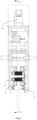
- a wood-plastic/lumber composite co-extrusion feeder includes a frame 10. At least one group of toothed conveying units 6, a tooth mark milling unit 8 for milling tooth marks on an outer surface of a lumber, and a lumber co-extrusion mold 9 are arranged on the frame 10 in sequence.
- Each toothed conveying unit 6 includes a lower toothed pressure roller 61 installed on a first fixed bearing seat and an upper toothed pressure roller 60 installed on a first movable bearing seat, and after the first fixed bearing seat and the first movable bearing seat are connected by an adjustment unit, a first conveying channel having an adjustable height is formed between the upper toothed pressure roller 60 and the lower-toothed pressure roller 61.
- the frame 10 is further provided with a speed regulating motor 2, at an output end of the speed regulating motor 2, a speed reducer 3 is installed and connected with the toothed conveying unit 6 and a rubber pressure roller unit 5 by a chain drive 4.
- the speed regulating motor 2 and the speed reducer 3 control a speed at which the lumber enters the mold by the chain drive, and the rubber pressure roller unit 5 controls an irregular error when the lumber enters initially.
- the toothed conveying unit 6 accurately controls a forward speed of the lumber and offsets a reverse resistance generated during operation of the milling cutter set in the tooth mark milling unit 8, and the two groups of limiting rubber roller sets define and maintain a forward linear position of the lumber.
- the lumber is milled into a precise-sized lumber by the milling cutter on a fine tooth mark milling machine and the tooth marks are pressed thereon, and then the lumber enters the wood-plastic/lumber composite co-extrusion mold 9.
- Hard alloy sharp teeth are densely distributed on the upper toothed pressure roller 60 and the lower toothed pressure roller 61, and bite into the surface of the lumber, so as to accurately control the forward speed of the lumber and offset the reverse resistance generated during operation of the milling cutter set in the tooth mark milling unit 8.
- a compressed spring and an adjusting nut are used for maintaining a pressure of the upper toothed pressure roller 60.
- a rubber pressure roller unit 5 is arranged which includes a lower rubber roller 51 installed on a second fixed bearing seat and an upper rubber roller 50 installed on a second movable bearing seat.
- a second conveying channel having an adjustable height is formed between the upper rubber roller 50 and the lower rubber roller 51, and an elastic rubber layer is sheathed on outer surfaces of the upper rubber roller 50 and the lower rubber roller 51.
- the upper rubber roller 50 and the lower rubber roller 51 have a large friction force and a corresponding elasticity, thus being able to adapt to the irregular error when the lumber enters initially. By replacing the middle fixed-length sleeve, it is suitable for the lumbers with different size requirements.
- the compressed spring and the adjusting nut are used for maintaining the pressure of the upper rubber roller 50.
- the adjustment unit includes a sliding rod, a fixed-length sleeve sheathed outside the sliding rod, an adjusting nut 63 for adjustment and a compressed spring 62 with one end pressed against the adjusting nut 63.
- One end of the adjusting nut 63 is respectively inserted into a corresponding movable bearing seat, one end of the compressed spring 62 is pressed against the corresponding movable bearing seat, and the other end of the compressed spring 62 is pressed against the adjusting nut 63.
- Each toothed conveying unit 6 is provided with a group of limiting rubber roller sets 7, each limiting rubber roller set 7 includes two holding brackets, a left limiting rubber roller and a right limiting rubber roller, and a plurality of bearing seats are arranged on each holding bracket.
- the left limiting rubber roller and the right limiting rubber roller are installed between two bearing seats of the corresponding holding brackets.
- a limiting space is formed between the left limiting rubber roller and the right limiting rubber roller.
- Two toothed conveying units 6 are provided, and the two toothed conveying units 6 are located between two groups of limiting rubber roller sets 7, which means that the two groups of limiting rubber roller sets 7 are installed at two sides of two groups of toothed conveying units 6 to limit and maintain the forward linear position of the lumber.
- the left limiting rubber roller and the right limiting rubber roller have a corresponding elasticity, thus being able to adapt to the irregular error when the lumber enters initially.
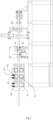
- the tooth mark milling unit 8 includes a first tooth mark milling mechanism for milling upper and lower surfaces of a lumber and a second tooth mark milling mechanism for milling left and right surfaces of the lumber.
- the first tooth mark milling mechanism includes a first milling cutter frame and a first tooth mark roller 81 located at a rear side of the first milling cutter frame
- the second tooth mark milling mechanism includes a second milling cutter frame and a second tooth mark roller 82 located at a rear side of the second milling cutter frame
- the first milling cutter frame and the second milling cutter frame are respectively provided with a milling cutter.
- the first tooth mark milling mechanism and the second tooth mark milling mechanism are respectively provided with a high-speed milling cutter motor.
- the first tooth mark milling mechanism is located at a front side of the second tooth mark milling mechanism.
- the lumber passes through the first tooth mark milling mechanism and the second tooth mark milling mechanism in sequence, and the corresponding milling cutters respectively process the upper and lower surfaces and the left and right surfaces of the lumber, the lumber is milled into the precise-sized lumber, and the tooth marks are pressed on the corresponding surfaces of the lumber by the first tooth mark roller 81 and the second tooth mark roller 82.
- the lumber enters the wood-plastic/lumber composite co-extrusion mold 9, and the tooth marks on the precise-sized lumber form an anchor chain effect with wood-plastic composite melt in the co-extrusion mold, thus increasing an interface bonding strength.
- a method for manufacturing a wood-plastic coated lumber composite which includes the following steps:
- the wood-plastic coated lumber composite includes the lumber core, the lumber core is coated with a wood-plastic composite layer, and the surface of the lumber core is provided with the point-like gear pressing marks.
- the continuous fiber mesh is also coated outside the lumber core with the point-like gear pressing marks, and the fiber mesh is coated and restrained by the wood-plastic composite layer.
- the high-strength fiber is at least one of a carbon fiber, a glass fiber, a basalt fiber, an aramid fiber, a polyester fiber, a polyamide fiber and a polyacrylonitrile fiber.
- the high-strength fiber is a fiber pre-soaked with a prepreg resin matrix
- the prepreg resin matrix is at least one of a wood-plastic composite or polypropylene, polyethylene, polyvinyl chloride, polylactic acid and polystyrene.
- the wood-plastic composite layer includes a first wood-plastic layer and a second wood-plastic layer which are connected, wherein the first wood-plastic layer is completely coated on the lumber core and the point-like gear pressing marks and forms a nail structure in the point-like gear pressing marks, the continuous fiber mesh is arranged between the first wood-plastic layer and the second wood-plastic layer, and the second wood-plastic layer is completely coated on the fiber mesh.
- a pressing mark depth is 0.5 mm to 4 mm independently; and a pressing mark density is 1 piece/cm 2 to 20 pieces/cm 2 independently, and is preferably 4 pieces/cm 2 to 10 pieces/cm 2 .
- thicknesses of the first wood-plastic layer and the second wood-plastic layer are 0.1 mm to 2 mm and 1 mm to 5 mm respectively.
- a raw material for the wood-plastic composite includes all wood fiber materials and mixtures thereof, and a thermoplastic polymer, such as PP ⁇ PE ⁇ PVC ⁇ PS ⁇ polylactic acid and a blend of the mixtures thereof.
- the wood-plastic composite consists of 40% (mass fraction) wood powder, 50t% (mass fraction) high-density polyethylene, 5 % talcum powder, 3 % coupling agent and 2 % lubricant.
- a wood-plastic coated lumber composite includes a lumber core.
- a cross section of the lumber core is 74 mm ⁇ 34 mm.
- a surface of the lumber core is provided with point-like gear pressing marks with a depth of 2 mm and a density of 10 pieces/cm 2 .
- a continuous fiber mesh is further coated outside the lumber core, and the fiber mesh is coated and restrained by the wood-plastic composite layer.
- the fiber mesh is formed by weaving or winding a continuous carbon fiber outside the lumber core.
- the wood-plastic composite layer is coated on the lumber core and the fiber mesh in a co-extruded manner, wherein the wood-plastic composite layer includes a first wood-plastic layer and a second wood-plastic layer.
- the first wood-plastic layer has a thickness of 1 mm
- the second wood-plastic layer has a thickness of 2 mm.
- the first wood-plastic layer is completely coated on the lumber core and the point-like gear pressing marks and forms a nail structure in the point-like gear pressing marks.
- the continuous fiber mesh is arranged between the first wood-plastic layer and the second wood-plastic layer, and the second wood-plastic layer is completely coated on the fiber mesh.
- the Embodiment 2 is the same as the Embodiment 1, except that the carbon fiber is pre-soaked with the wood-plastic composite.
- the Embodiment 3 is the same as the Embodiment 1, except that the pressing mark depth is 4 mm.
- the Embodiment 4 is the same as the Embodiment 1, except that the pressing mark depth is 0.5mm.
- the Embodiment 5 is the same as the Embodiment 3, except that the carbon fiber is pre-soaked with the wood-plastic composite.
- the Embodiment 6 is the same as the Embodiment 2, except that the pressing mark density is 5 pieces/cm 2 .
- the Embodiment 7 is the same as the Embodiment 2, except that the pressing mark density is 1 piece/cm 2 .
- the Embodiment 8 is the same as the Embodiment 2, except that the pressing mark density is 25 pieces/cm 2 .
- the Comparative Embodiment 1 is the same as the Embodiment 1, except that the pressing mark depth is 0.3mm.
- the Comparative Embodiment 2 is the same as the Embodiment 1, except that the continuous fiber mesh is not coated outside the lumber core.
- the Comparative Embodiment 3 is the same as the Embodiment 1, except that the surface of the lumber core has no pressing mark.
- the Comparative Embodiment 4 is the same as the Embodiment 1, except that the surface of the lumber core has no pressing mark, and the continuous fiber mesh is not coated outside the lumber core.
- Interface bonding strength (MPa) Embodiment 1 1.07 to 1.26 Embodiment 2 1.28 to 1.59 Embodiment 3 1.21 to 1.49 Embodiment 4 0.51 to 0.75 Embodiment 5 1.55 to 1.91 Embodiment 6 1.11 to 1.34 Embodiment 7 0.92 to 1.10 Embodiment 8 1.33 to 1.67 Comparative Embodiment 1 0.42 to 0.64 Comparative Embodiment 2 0.40 to 0.61 Comparative Embodiment 3 0.33 to 0.54 Comparative Embodiment 4 0.22 to 0.37
- the pressing marks on the surface of the lumber core and the coated continuous fiber mesh are able to greatly improve the interface bonding strength, and the pressing mark depth has a positive correlation with the interface bonding strength within a certain range.
- the pressing mark depth is higher than a certain range, the interface bonding strength is not improved significantly.
- the carbon fiber pre-soaked with the wood-plastic composite can better improve the interface bonding strength. Increasing the pressing mark density in a certain range is beneficial for improving the interface bonding strength.
Landscapes
- Engineering & Computer Science (AREA)
- Mechanical Engineering (AREA)
- Life Sciences & Earth Sciences (AREA)
- Wood Science & Technology (AREA)
- Forests & Forestry (AREA)
- Extrusion Moulding Of Plastics Or The Like (AREA)
- Dry Formation Of Fiberboard And The Like (AREA)
- Laminated Bodies (AREA)
Claims (5)
- Verfahren zur Herstellung von mit Holz-Kunststoff beschichtetem Bauholzverbundwerkstoff, umfassend die folgenden Schritte:1) Zuführen eines Bauholzkerns durch eine Holz-Kunststoff/Bauholzverbundwerkstoff-Coextrusionszuführvorrichtung, wobei die Holz-Kunststoff/Bauholzverbundwerkstoff-Coextrusionszuführvorrichtung ein Gestell (10) umfasst, wobei mindestens eine Gruppe von Zahnfördereinheiten (6), einer Zahnabdruckfräseeinheit (8) zum Fräsen von Zahnabdrücken auf eine äußere Oberfläche eines Bauholzes und eines Bauholz-Coextrusionswerkzeugs (9) auf dem Gerüst (10) der Reihe nach eingerichtet ist, jede Zahnfördereinheit (6) eine untere Zahnandruckwalze (61), die auf einem ersten fixierten Lagersitz installiert ist, und eine obere Zahnandruckwalze (60), die auf einem ersten beweglichen Lagersitz installiert ist, umfasst und, nachdem der erste fixierte Lagersitz und der erste bewegliche Lagersitz durch eine Einstellungseinheit verbunden wurden, ein erster Förderkanal mit einer einstellbaren Höhe zwischen der oberen Zahnandruckwalze (60) und der unteren Zahnandruckwalze (61) gebildet wird, und Verarbeiten des Bauholzkerns, um punktartige Zahnraddruckmarkierungen auf dem Bauholzkern zu bilden;2) Weben oder Wickeln einer kontinuierlichen Faser hoher Festigkeit auf eine Oberfläche des Bauholzkerns, um ein Fasernetzwerk zu bilden; und3) Coextrudieren außerhalb des Fasernetzwerks, um eine Holz-Kunststoff-Schicht zu bilden, um einen mit Holz-Kunststoff beschichteten Bauholzverbundwerkstoff zu erhalten.
- Verfahren nach Anspruch 1, wobei der mit Holz-Kunststoff beschichtete Bauholzverbundwerkstoff den Bauholzkern umfasst, der mit einer Holz-Kunststoff-Verbundwerkstoffschicht beschichtet ist, und die Oberfläche des Bauholzkerns mit den punktartigen Zahnraddruckmarkierungen versehen ist; das kontinuierliche Fasernetzwerk ferner außerhalb des Bauholzkerns mit den punktartigen Zahnraddruckmarkierungen beschichtet ist und das Fasernetzwerk mit der Holz-Kunststoff-Verbundwerkstoffsschicht beschichtet und durch diese abgegrenzt ist; und die Faser hoher Festigkeit mindestens eine von einer Kohlefaser, einer Glasfaser, einer Basaltfaser, einer Aramidfaser, einer Polyesterfaser, einer Polyamidfaser und einer Polyacrylnitrilfaser ist.
- Verfahren nach Anspruch 1 oder 2, wobei die Faser hoher Festigkeit eine Faser ist, die zuvor mit einer Prepreg-Harzmatrix getränkt wurde, und die Prepreg-Harzmatrix mindestens einer bzw. eines von einem Holz-Kunststoff-Verbundwerkstoff oder Polypropylen, Polyethylen, Polyvinylchlorid, Polymilchsäure und Polystyrol ist; die Holz-Kunststoff-Verbundwerkstoffsschicht eine erste Holz-Kunststoff-Schicht und eine zweite Holz-Kunststoff-Schicht umfasst, die verbunden sind, wobei die erste Holz-Kunststoff-Schicht vollständig auf den Bauholzkern und die punktartigen Zahnraddruckmarkierungen beschichtet ist und eine Nagelstruktur in den punktartigen Zahnraddruckmarkierungen bildet, das kontinuierliche Fasernetzwerk zwischen der ersten Holz-Kunststoff-Schicht und der zweiten Holz-Kunststoff-Schicht eingerichtet ist und die zweite Holz-Kunststoff-Schicht vollständig auf das Fasernetzwerk beschichtet ist.
- Verfahren nach den Ansprüchen 1 bis 3, wobei eine Druckmarkierungstiefe unabhängig 0,5 mm bis 4 mm beträgt; und eine Druckmarkierungsdichte unabhängig 1 Stück/cm2 bis 20 Stück/cm2 beträgt und vorzugsweise 4 Stück/cm2 bis 10 Stück/cm2 beträgt.
- Verfahren nach den Ansprüchen 1 bis 4, wobei Dicken der ersten Holz-Kunststoff-Schicht und der zweiten Holz-Kunststoff-Schicht 0,1 mm bis 2 mm bzw. 1 mm bis 5 mm betragen.
Applications Claiming Priority (3)
| Application Number | Priority Date | Filing Date | Title |
|---|---|---|---|
| CN201910014126.7A CN109822858B (zh) | 2019-01-08 | 2019-01-08 | 一种木塑实木共挤送料机 |
| CN201910014163.8A CN109849447B (zh) | 2019-01-08 | 2019-01-08 | 一种木塑包覆实木复合材料及其制备方法 |
| PCT/CN2019/128960 WO2020143476A1 (zh) | 2019-01-08 | 2019-12-27 | 一种木塑包覆实木复合材料的制造设备及方法 |
Publications (4)
| Publication Number | Publication Date |
|---|---|
| EP3756853A1 EP3756853A1 (de) | 2020-12-30 |
| EP3756853A4 EP3756853A4 (de) | 2021-06-23 |
| EP3756853C0 EP3756853C0 (de) | 2023-09-06 |
| EP3756853B1 true EP3756853B1 (de) | 2023-09-06 |
Family
ID=71520226
Family Applications (1)
| Application Number | Title | Priority Date | Filing Date |
|---|---|---|---|
| EP19909157.0A Active EP3756853B1 (de) | 2019-01-08 | 2019-12-27 | Vorrichtung und verfahren zur herstellung von mit holzkunststoff beschichtetem massivholzverbundmaterial |
Country Status (4)
| Country | Link |
|---|---|
| US (1) | US11865759B2 (de) |
| EP (1) | EP3756853B1 (de) |
| JP (1) | JP7087105B2 (de) |
| WO (1) | WO2020143476A1 (de) |
Families Citing this family (5)
| Publication number | Priority date | Publication date | Assignee | Title |
|---|---|---|---|---|
| CN114311587A (zh) * | 2021-12-28 | 2022-04-12 | 南通新帝克单丝科技股份有限公司 | 用于聚合物单丝涂覆成型的生产装置 |
| CN114523609A (zh) * | 2021-12-31 | 2022-05-24 | 安徽科居新材料科技有限公司 | 具有环保功能的塑木加工输送设备及其方法 |
| TWI835321B (zh) * | 2022-09-29 | 2024-03-11 | 莊承翰 | 仿木粗糙面的成型方法及系統 |
| DE102022128404A1 (de) * | 2022-10-26 | 2024-05-02 | Coperion Gmbh | Modulare Produktionsanlage und Verfahren zum Auslegen einer Produktionsanlage |
| CN117052266B (zh) * | 2023-08-11 | 2024-01-16 | 江西立立联新型建材有限公司 | 一种塑木共挤型骨架的门扇的包边设备 |
Family Cites Families (25)
| Publication number | Priority date | Publication date | Assignee | Title |
|---|---|---|---|---|
| GB190417603A (en) * | 1904-08-12 | 1905-08-12 | George Skaats Mayhew | Improvements in and relating to Fireproof Wooden-cored Plaster Slabs for Building and other purposes and in Machines for Making the same. |
| US3323172A (en) * | 1965-01-22 | 1967-06-06 | Weyerhaeuser Co | Extrusion apparatus |
| JPS5695656A (en) | 1979-12-28 | 1981-08-03 | Sekisui Chem Co Ltd | Production of three-layer construction |
| CN2275024Y (zh) | 1996-12-25 | 1998-02-25 | 张君明 | 多功能装饰板材加工设备 |
| CN2330484Y (zh) * | 1998-04-29 | 1999-07-28 | 台圳木工机械(北京)有限公司 | 具有新型送料装置的集成材纵接机 |
| JP2004174721A (ja) * | 2002-11-22 | 2004-06-24 | Iris Ohyama Inc | 木質系成形体及びその製造方法 |
| US7175905B2 (en) * | 2003-11-17 | 2007-02-13 | Barry James Curtis | Composite coated/encapsulated wood products and methods to produce the same |
| DE102004010873A1 (de) | 2004-03-05 | 2005-09-22 | Homag Holzbearbeitungssysteme Ag | Verfahren und Vorrichtung zur Herstellung einer Leichtbauplatte |
| CN1833836A (zh) | 2005-03-15 | 2006-09-20 | 苏泉窝 | 木工不定长双端铣齿机 |
| CN200957620Y (zh) | 2006-08-17 | 2007-10-10 | 刘岳法 | 多喂入竹木滚切铣条机 |
| JP5396066B2 (ja) * | 2008-11-05 | 2014-01-22 | 株式会社山本鉄工所 | 木芯プラスチック成形体とその製造方法 |
| CN101871299A (zh) | 2009-04-21 | 2010-10-27 | 无锡百沐得科技有限公司 | 拉挤竹玻带玻璃钢空腹门窗异型材及成型方法 |
| CN102189575A (zh) | 2010-03-09 | 2011-09-21 | 中江县宏泰木业有限责任公司 | 木板打齿装置 |
| CN102431245A (zh) | 2011-09-08 | 2012-05-02 | 宁波雄歌进出口有限公司 | 一种塑竹板材及其生产工艺 |
| CN202607781U (zh) | 2012-03-31 | 2012-12-19 | 漳州喜盈门家具制品有限公司 | 木材自动对接机 |
| CN202726478U (zh) * | 2012-05-14 | 2013-02-13 | 廊坊开发区罗宝建筑节能材料有限公司 | 罗宝板压痕铣槽机 |
| CN103732042B (zh) | 2013-12-11 | 2016-06-01 | 上海交通大学 | 特殊环境中的关键器件的恒温恒压保护系统 |
| CN104210080B (zh) | 2014-09-12 | 2016-09-28 | 王清文 | 一种木塑实木复合材料共挤出成型装置 |
| CN104228236A (zh) | 2014-09-15 | 2014-12-24 | 王清文 | 一种木塑包覆实木复合材料及其制备方法 |
| CN106065194A (zh) | 2016-06-12 | 2016-11-02 | 王海刚 | 一种连续纤维增强的木塑复合材料及其制备方法 |
| CN106113738B (zh) | 2016-07-15 | 2019-01-04 | 广东新秀新材料股份有限公司 | 夹层结构复合材料及其制备方法 |
| CN107866878A (zh) | 2017-11-17 | 2018-04-03 | 成都古蜀乌木工艺品厂 | 能够提高效率的木材切片机 |
| CN108162094A (zh) | 2018-02-26 | 2018-06-15 | 台山市新英汉装饰材料有限公司 | 一种具有自动送料系统的木板贴纸设备 |
| CN109822858B (zh) | 2019-01-08 | 2021-05-14 | 华南农业大学 | 一种木塑实木共挤送料机 |
| CN109849447B (zh) | 2019-01-08 | 2019-12-17 | 华南农业大学 | 一种木塑包覆实木复合材料及其制备方法 |
-
2019
- 2019-12-27 WO PCT/CN2019/128960 patent/WO2020143476A1/zh not_active Ceased
- 2019-12-27 US US17/047,344 patent/US11865759B2/en active Active
- 2019-12-27 EP EP19909157.0A patent/EP3756853B1/de active Active
- 2019-12-27 JP JP2020552788A patent/JP7087105B2/ja active Active
Also Published As
| Publication number | Publication date |
|---|---|
| EP3756853A1 (de) | 2020-12-30 |
| WO2020143476A1 (zh) | 2020-07-16 |
| US11865759B2 (en) | 2024-01-09 |
| EP3756853C0 (de) | 2023-09-06 |
| JP7087105B2 (ja) | 2022-06-20 |
| EP3756853A4 (de) | 2021-06-23 |
| JP2021517083A (ja) | 2021-07-15 |
| US20210138710A1 (en) | 2021-05-13 |
Similar Documents
| Publication | Publication Date | Title |
|---|---|---|
| EP3756853B1 (de) | Vorrichtung und verfahren zur herstellung von mit holzkunststoff beschichtetem massivholzverbundmaterial | |
| EP3170951B1 (de) | Hochfeste pvc-plattenboden und herstellungsverfahren dafür | |
| US8852475B2 (en) | Method of making continuous filament reinforced structural plastic profiles using pultrusion/coextrusion | |
| US7987885B2 (en) | System and die for forming a continuous filament reinforced structural plastic profile by pultrusion/coextrusion | |
| CN111003968A (zh) | 高性能生态石晶地板及其制备工艺 | |
| WO2009152682A1 (zh) | 一种纤维网格塑料板及其制备方法 | |
| CN111038051A (zh) | Pvc和asa共挤型材及其制备方法 | |
| CN113771451A (zh) | 一种多层包覆共挤型材及其生产方法 | |
| CN105542346A (zh) | 用于r-pvc型材共挤表层的复合材料及其制备方法 | |
| CN106674822A (zh) | 木塑地板及其制作方法 | |
| EP3140098B1 (de) | Verfahren zur herstellung von paneelen für boden- und wandabdeckungen | |
| CN109849447B (zh) | 一种木塑包覆实木复合材料及其制备方法 | |
| CN110406222A (zh) | 一种发泡pvc共挤耐候花箱型材及其制备方法 | |
| CN217553378U (zh) | 一种生物基聚酰胺复合板材 | |
| CN102643466A (zh) | 应用于pe木塑及相关材料的共挤复合材料及其制备方法 | |
| CN113334881A (zh) | 一体成型高耐候增韧矿物竹木复合共挤板材及其制备方法 | |
| CN109869540B (zh) | 一种frp条带增强热塑性树脂螺旋波纹管 | |
| CN109694535B (zh) | 一种工程塑料合金复合建筑模板及其制备方法 | |
| CN1334186A (zh) | 高密度聚乙烯低发泡板条及其生产工艺 | |
| CN109822858B (zh) | 一种木塑实木共挤送料机 | |
| CN113524839A (zh) | 一种双向增强pp板材及其制备方法 | |
| CN112724552A (zh) | 一种pvc-m抗冲击管材及其制备方法 | |
| CN103540115A (zh) | 一种新型节能建筑材料的制备方法 | |
| CN112026311A (zh) | Pvc和pc/asa合金共挤防变形阻燃天花板材及其制备方法 | |
| CN202156420U (zh) | 一种高性能金属复合吊顶板 |
Legal Events
| Date | Code | Title | Description |
|---|---|---|---|
| STAA | Information on the status of an ep patent application or granted ep patent |
Free format text: STATUS: THE INTERNATIONAL PUBLICATION HAS BEEN MADE |
|
| PUAI | Public reference made under article 153(3) epc to a published international application that has entered the european phase |
Free format text: ORIGINAL CODE: 0009012 |
|
| STAA | Information on the status of an ep patent application or granted ep patent |
Free format text: STATUS: REQUEST FOR EXAMINATION WAS MADE |
|
| 17P | Request for examination filed |
Effective date: 20200924 |
|
| AK | Designated contracting states |
Kind code of ref document: A1 Designated state(s): AL AT BE BG CH CY CZ DE DK EE ES FI FR GB GR HR HU IE IS IT LI LT LU LV MC MK MT NL NO PL PT RO RS SE SI SK SM TR |
|
| AX | Request for extension of the european patent |
Extension state: BA ME |
|
| RIN1 | Information on inventor provided before grant (corrected) |
Inventor name: OU, RONGXIAN Inventor name: XU, JUNJIE Inventor name: SUN, LICHAO Inventor name: WANG, QINGWEN Inventor name: YI, XIN Inventor name: TANG, WEI |
|
| A4 | Supplementary search report drawn up and despatched |
Effective date: 20210527 |
|
| RIC1 | Information provided on ipc code assigned before grant |
Ipc: B29C 48/285 20190101AFI20210520BHEP Ipc: B29C 48/154 20190101ALI20210520BHEP Ipc: B27M 1/00 20060101ALI20210520BHEP |
|
| DAV | Request for validation of the european patent (deleted) | ||
| DAX | Request for extension of the european patent (deleted) | ||
| GRAP | Despatch of communication of intention to grant a patent |
Free format text: ORIGINAL CODE: EPIDOSNIGR1 |
|
| STAA | Information on the status of an ep patent application or granted ep patent |
Free format text: STATUS: GRANT OF PATENT IS INTENDED |
|
| INTG | Intention to grant announced |
Effective date: 20230609 |
|
| GRAS | Grant fee paid |
Free format text: ORIGINAL CODE: EPIDOSNIGR3 |
|
| GRAA | (expected) grant |
Free format text: ORIGINAL CODE: 0009210 |
|
| STAA | Information on the status of an ep patent application or granted ep patent |
Free format text: STATUS: THE PATENT HAS BEEN GRANTED |
|
| AK | Designated contracting states |
Kind code of ref document: B1 Designated state(s): AL AT BE BG CH CY CZ DE DK EE ES FI FR GB GR HR HU IE IS IT LI LT LU LV MC MK MT NL NO PL PT RO RS SE SI SK SM TR |
|
| REG | Reference to a national code |
Ref country code: GB Ref legal event code: FG4D |
|
| REG | Reference to a national code |
Ref country code: CH Ref legal event code: EP |
|
| REG | Reference to a national code |
Ref country code: IE Ref legal event code: FG4D |
|
| REG | Reference to a national code |
Ref country code: DE Ref legal event code: R096 Ref document number: 602019037158 Country of ref document: DE |
|
| U01 | Request for unitary effect filed |
Effective date: 20231002 |
|
| U07 | Unitary effect registered |
Designated state(s): AT BE BG DE DK EE FI FR IT LT LU LV MT NL PT SE SI Effective date: 20231011 |
|
| PG25 | Lapsed in a contracting state [announced via postgrant information from national office to epo] |
Ref country code: GR Free format text: LAPSE BECAUSE OF FAILURE TO SUBMIT A TRANSLATION OF THE DESCRIPTION OR TO PAY THE FEE WITHIN THE PRESCRIBED TIME-LIMIT Effective date: 20231207 |
|
| U20 | Renewal fee for the european patent with unitary effect paid |
Year of fee payment: 5 Effective date: 20231219 |
|
| PG25 | Lapsed in a contracting state [announced via postgrant information from national office to epo] |
Ref country code: RS Free format text: LAPSE BECAUSE OF FAILURE TO SUBMIT A TRANSLATION OF THE DESCRIPTION OR TO PAY THE FEE WITHIN THE PRESCRIBED TIME-LIMIT Effective date: 20230906 Ref country code: NO Free format text: LAPSE BECAUSE OF FAILURE TO SUBMIT A TRANSLATION OF THE DESCRIPTION OR TO PAY THE FEE WITHIN THE PRESCRIBED TIME-LIMIT Effective date: 20231206 Ref country code: HR Free format text: LAPSE BECAUSE OF FAILURE TO SUBMIT A TRANSLATION OF THE DESCRIPTION OR TO PAY THE FEE WITHIN THE PRESCRIBED TIME-LIMIT Effective date: 20230906 Ref country code: GR Free format text: LAPSE BECAUSE OF FAILURE TO SUBMIT A TRANSLATION OF THE DESCRIPTION OR TO PAY THE FEE WITHIN THE PRESCRIBED TIME-LIMIT Effective date: 20231207 |
|
| PG25 | Lapsed in a contracting state [announced via postgrant information from national office to epo] |
Ref country code: IS Free format text: LAPSE BECAUSE OF FAILURE TO SUBMIT A TRANSLATION OF THE DESCRIPTION OR TO PAY THE FEE WITHIN THE PRESCRIBED TIME-LIMIT Effective date: 20240106 |
|
| PG25 | Lapsed in a contracting state [announced via postgrant information from national office to epo] |
Ref country code: ES Free format text: LAPSE BECAUSE OF FAILURE TO SUBMIT A TRANSLATION OF THE DESCRIPTION OR TO PAY THE FEE WITHIN THE PRESCRIBED TIME-LIMIT Effective date: 20230906 |
|
| PG25 | Lapsed in a contracting state [announced via postgrant information from national office to epo] |
Ref country code: SM Free format text: LAPSE BECAUSE OF FAILURE TO SUBMIT A TRANSLATION OF THE DESCRIPTION OR TO PAY THE FEE WITHIN THE PRESCRIBED TIME-LIMIT Effective date: 20230906 Ref country code: RO Free format text: LAPSE BECAUSE OF FAILURE TO SUBMIT A TRANSLATION OF THE DESCRIPTION OR TO PAY THE FEE WITHIN THE PRESCRIBED TIME-LIMIT Effective date: 20230906 Ref country code: IS Free format text: LAPSE BECAUSE OF FAILURE TO SUBMIT A TRANSLATION OF THE DESCRIPTION OR TO PAY THE FEE WITHIN THE PRESCRIBED TIME-LIMIT Effective date: 20240106 Ref country code: ES Free format text: LAPSE BECAUSE OF FAILURE TO SUBMIT A TRANSLATION OF THE DESCRIPTION OR TO PAY THE FEE WITHIN THE PRESCRIBED TIME-LIMIT Effective date: 20230906 Ref country code: CZ Free format text: LAPSE BECAUSE OF FAILURE TO SUBMIT A TRANSLATION OF THE DESCRIPTION OR TO PAY THE FEE WITHIN THE PRESCRIBED TIME-LIMIT Effective date: 20230906 Ref country code: SK Free format text: LAPSE BECAUSE OF FAILURE TO SUBMIT A TRANSLATION OF THE DESCRIPTION OR TO PAY THE FEE WITHIN THE PRESCRIBED TIME-LIMIT Effective date: 20230906 |
|
| PG25 | Lapsed in a contracting state [announced via postgrant information from national office to epo] |
Ref country code: PL Free format text: LAPSE BECAUSE OF FAILURE TO SUBMIT A TRANSLATION OF THE DESCRIPTION OR TO PAY THE FEE WITHIN THE PRESCRIBED TIME-LIMIT Effective date: 20230906 |
|
| REG | Reference to a national code |
Ref country code: DE Ref legal event code: R097 Ref document number: 602019037158 Country of ref document: DE |
|
| PLBE | No opposition filed within time limit |
Free format text: ORIGINAL CODE: 0009261 |
|
| STAA | Information on the status of an ep patent application or granted ep patent |
Free format text: STATUS: NO OPPOSITION FILED WITHIN TIME LIMIT |
|
| REG | Reference to a national code |
Ref country code: CH Ref legal event code: PL |
|
| 26N | No opposition filed |
Effective date: 20240607 |
|
| PG25 | Lapsed in a contracting state [announced via postgrant information from national office to epo] |
Ref country code: MC Free format text: LAPSE BECAUSE OF FAILURE TO SUBMIT A TRANSLATION OF THE DESCRIPTION OR TO PAY THE FEE WITHIN THE PRESCRIBED TIME-LIMIT Effective date: 20230906 |
|
| GBPC | Gb: european patent ceased through non-payment of renewal fee |
Effective date: 20231227 |
|
| PG25 | Lapsed in a contracting state [announced via postgrant information from national office to epo] |
Ref country code: MC Free format text: LAPSE BECAUSE OF FAILURE TO SUBMIT A TRANSLATION OF THE DESCRIPTION OR TO PAY THE FEE WITHIN THE PRESCRIBED TIME-LIMIT Effective date: 20230906 |
|
| REG | Reference to a national code |
Ref country code: IE Ref legal event code: MM4A |
|
| PG25 | Lapsed in a contracting state [announced via postgrant information from national office to epo] |
Ref country code: IE Free format text: LAPSE BECAUSE OF NON-PAYMENT OF DUE FEES Effective date: 20231227 |
|
| PG25 | Lapsed in a contracting state [announced via postgrant information from national office to epo] |
Ref country code: GB Free format text: LAPSE BECAUSE OF NON-PAYMENT OF DUE FEES Effective date: 20231227 |
|
| PG25 | Lapsed in a contracting state [announced via postgrant information from national office to epo] |
Ref country code: CH Free format text: LAPSE BECAUSE OF NON-PAYMENT OF DUE FEES Effective date: 20231231 |
|
| PG25 | Lapsed in a contracting state [announced via postgrant information from national office to epo] |
Ref country code: IE Free format text: LAPSE BECAUSE OF NON-PAYMENT OF DUE FEES Effective date: 20231227 Ref country code: GB Free format text: LAPSE BECAUSE OF NON-PAYMENT OF DUE FEES Effective date: 20231227 Ref country code: CH Free format text: LAPSE BECAUSE OF NON-PAYMENT OF DUE FEES Effective date: 20231231 |
|
| U20 | Renewal fee for the european patent with unitary effect paid |
Year of fee payment: 6 Effective date: 20241205 |
|
| PG25 | Lapsed in a contracting state [announced via postgrant information from national office to epo] |
Ref country code: CY Free format text: LAPSE BECAUSE OF FAILURE TO SUBMIT A TRANSLATION OF THE DESCRIPTION OR TO PAY THE FEE WITHIN THE PRESCRIBED TIME-LIMIT; INVALID AB INITIO Effective date: 20191227 |
|
| PG25 | Lapsed in a contracting state [announced via postgrant information from national office to epo] |
Ref country code: HU Free format text: LAPSE BECAUSE OF FAILURE TO SUBMIT A TRANSLATION OF THE DESCRIPTION OR TO PAY THE FEE WITHIN THE PRESCRIBED TIME-LIMIT; INVALID AB INITIO Effective date: 20191227 |
|
| PG25 | Lapsed in a contracting state [announced via postgrant information from national office to epo] |
Ref country code: TR Free format text: LAPSE BECAUSE OF FAILURE TO SUBMIT A TRANSLATION OF THE DESCRIPTION OR TO PAY THE FEE WITHIN THE PRESCRIBED TIME-LIMIT Effective date: 20230906 |
|
| U20 | Renewal fee for the european patent with unitary effect paid |
Year of fee payment: 7 Effective date: 20251110 |