EP3756853B1 - Device and method for manufacturing wood-plastic coated solid wood composite material - Google Patents
Device and method for manufacturing wood-plastic coated solid wood composite material Download PDFInfo
- Publication number
- EP3756853B1 EP3756853B1 EP19909157.0A EP19909157A EP3756853B1 EP 3756853 B1 EP3756853 B1 EP 3756853B1 EP 19909157 A EP19909157 A EP 19909157A EP 3756853 B1 EP3756853 B1 EP 3756853B1
- Authority
- EP
- European Patent Office
- Prior art keywords
- wood
- lumber
- plastic
- fiber
- composite
- Prior art date
- Legal status (The legal status is an assumption and is not a legal conclusion. Google has not performed a legal analysis and makes no representation as to the accuracy of the status listed.)
- Active
Links
- 229920003023 plastic Polymers 0.000 title claims description 83
- 239000004033 plastic Substances 0.000 title claims description 83
- 239000002131 composite material Substances 0.000 title claims description 38
- 238000000034 method Methods 0.000 title claims description 21
- 238000004519 manufacturing process Methods 0.000 title claims description 20
- 239000002023 wood Substances 0.000 title description 18
- 239000007787 solid Substances 0.000 title 1
- 238000003801 milling Methods 0.000 claims description 50
- 239000000835 fiber Substances 0.000 claims description 48
- 238000003825 pressing Methods 0.000 claims description 36
- 229920001587 Wood-plastic composite Polymers 0.000 claims description 34
- 239000011155 wood-plastic composite Substances 0.000 claims description 34
- 238000001125 extrusion Methods 0.000 claims description 33
- 229920000049 Carbon (fiber) Polymers 0.000 claims description 7
- 239000004917 carbon fiber Substances 0.000 claims description 7
- VNWKTOKETHGBQD-UHFFFAOYSA-N methane Chemical compound C VNWKTOKETHGBQD-UHFFFAOYSA-N 0.000 claims description 7
- 239000011159 matrix material Substances 0.000 claims description 6
- -1 polypropylene Polymers 0.000 claims description 6
- 229920005989 resin Polymers 0.000 claims description 6
- 239000011347 resin Substances 0.000 claims description 6
- 239000004698 Polyethylene Substances 0.000 claims description 4
- 239000004743 Polypropylene Substances 0.000 claims description 4
- 239000004793 Polystyrene Substances 0.000 claims description 4
- 229920000747 poly(lactic acid) Polymers 0.000 claims description 4
- 239000004626 polylactic acid Substances 0.000 claims description 4
- 239000004800 polyvinyl chloride Substances 0.000 claims description 4
- 229920000915 polyvinyl chloride Polymers 0.000 claims description 4
- 238000009941 weaving Methods 0.000 claims description 4
- 238000004804 winding Methods 0.000 claims description 4
- 229920002748 Basalt fiber Polymers 0.000 claims description 3
- 239000004952 Polyamide Substances 0.000 claims description 3
- 229920006231 aramid fiber Polymers 0.000 claims description 3
- 239000003365 glass fiber Substances 0.000 claims description 3
- 229920002239 polyacrylonitrile Polymers 0.000 claims description 3
- 229920002647 polyamide Polymers 0.000 claims description 3
- 229920000728 polyester Polymers 0.000 claims description 3
- 229920000573 polyethylene Polymers 0.000 claims description 3
- 229920001155 polypropylene Polymers 0.000 claims description 3
- 229920002223 polystyrene Polymers 0.000 claims description 3
- 239000005060 rubber Substances 0.000 description 41
- 239000010410 layer Substances 0.000 description 38
- 239000011162 core material Substances 0.000 description 34
- 230000000052 comparative effect Effects 0.000 description 13
- 239000000463 material Substances 0.000 description 12
- 230000007797 corrosion Effects 0.000 description 5
- 238000005260 corrosion Methods 0.000 description 5
- 230000007547 defect Effects 0.000 description 5
- 230000001788 irregular Effects 0.000 description 5
- 230000000694 effects Effects 0.000 description 4
- XLYOFNOQVPJJNP-UHFFFAOYSA-N water Substances O XLYOFNOQVPJJNP-UHFFFAOYSA-N 0.000 description 4
- 230000008878 coupling Effects 0.000 description 3
- 238000010168 coupling process Methods 0.000 description 3
- 238000005859 coupling reaction Methods 0.000 description 3
- 238000005516 engineering process Methods 0.000 description 3
- 239000000203 mixture Substances 0.000 description 3
- 230000001105 regulatory effect Effects 0.000 description 3
- 229920002522 Wood fibre Polymers 0.000 description 2
- 230000009286 beneficial effect Effects 0.000 description 2
- 239000003638 chemical reducing agent Substances 0.000 description 2
- 230000007613 environmental effect Effects 0.000 description 2
- 239000002184 metal Substances 0.000 description 2
- 239000000243 solution Substances 0.000 description 2
- 229920001169 thermoplastic Polymers 0.000 description 2
- 239000002025 wood fiber Substances 0.000 description 2
- 239000000956 alloy Substances 0.000 description 1
- 229910045601 alloy Inorganic materials 0.000 description 1
- 230000000295 complement effect Effects 0.000 description 1
- 238000010924 continuous production Methods 0.000 description 1
- 239000012792 core layer Substances 0.000 description 1
- 239000007822 coupling agent Substances 0.000 description 1
- 238000005336 cracking Methods 0.000 description 1
- 238000005034 decoration Methods 0.000 description 1
- 238000010586 diagram Methods 0.000 description 1
- FPAFDBFIGPHWGO-UHFFFAOYSA-N dioxosilane;oxomagnesium;hydrate Chemical compound O.[Mg]=O.[Mg]=O.[Mg]=O.O=[Si]=O.O=[Si]=O.O=[Si]=O.O=[Si]=O FPAFDBFIGPHWGO-UHFFFAOYSA-N 0.000 description 1
- 229920001903 high density polyethylene Polymers 0.000 description 1
- 239000004700 high-density polyethylene Substances 0.000 description 1
- 238000001746 injection moulding Methods 0.000 description 1
- 239000000314 lubricant Substances 0.000 description 1
- 230000000149 penetrating effect Effects 0.000 description 1
- 239000000843 powder Substances 0.000 description 1
- 239000002994 raw material Substances 0.000 description 1
- 238000004064 recycling Methods 0.000 description 1
- 239000002344 surface layer Substances 0.000 description 1
Images

Classifications
-
- B—PERFORMING OPERATIONS; TRANSPORTING
- B29—WORKING OF PLASTICS; WORKING OF SUBSTANCES IN A PLASTIC STATE IN GENERAL
- B29C—SHAPING OR JOINING OF PLASTICS; SHAPING OF MATERIAL IN A PLASTIC STATE, NOT OTHERWISE PROVIDED FOR; AFTER-TREATMENT OF THE SHAPED PRODUCTS, e.g. REPAIRING
- B29C48/00—Extrusion moulding, i.e. expressing the moulding material through a die or nozzle which imparts the desired form; Apparatus therefor
- B29C48/25—Component parts, details or accessories; Auxiliary operations
- B29C48/285—Feeding the extrusion material to the extruder
- B29C48/288—Feeding the extrusion material to the extruder in solid form, e.g. powder or granules
- B29C48/2883—Feeding the extrusion material to the extruder in solid form, e.g. powder or granules of preformed parts, e.g. inserts fed and transported generally uninfluenced through the extruder or inserts fed directly to the die
-
- B—PERFORMING OPERATIONS; TRANSPORTING
- B29—WORKING OF PLASTICS; WORKING OF SUBSTANCES IN A PLASTIC STATE IN GENERAL
- B29C—SHAPING OR JOINING OF PLASTICS; SHAPING OF MATERIAL IN A PLASTIC STATE, NOT OTHERWISE PROVIDED FOR; AFTER-TREATMENT OF THE SHAPED PRODUCTS, e.g. REPAIRING
- B29C48/00—Extrusion moulding, i.e. expressing the moulding material through a die or nozzle which imparts the desired form; Apparatus therefor
- B29C48/15—Extrusion moulding, i.e. expressing the moulding material through a die or nozzle which imparts the desired form; Apparatus therefor incorporating preformed parts or layers, e.g. extrusion moulding around inserts
- B29C48/154—Coating solid articles, i.e. non-hollow articles
-
- B—PERFORMING OPERATIONS; TRANSPORTING
- B27—WORKING OR PRESERVING WOOD OR SIMILAR MATERIAL; NAILING OR STAPLING MACHINES IN GENERAL
- B27C—PLANING, DRILLING, MILLING, TURNING OR UNIVERSAL MACHINES FOR WOOD OR SIMILAR MATERIAL
- B27C1/00—Machines for producing flat surfaces, e.g. by rotary cutters; Equipment therefor
-
- B—PERFORMING OPERATIONS; TRANSPORTING
- B29—WORKING OF PLASTICS; WORKING OF SUBSTANCES IN A PLASTIC STATE IN GENERAL
- B29C—SHAPING OR JOINING OF PLASTICS; SHAPING OF MATERIAL IN A PLASTIC STATE, NOT OTHERWISE PROVIDED FOR; AFTER-TREATMENT OF THE SHAPED PRODUCTS, e.g. REPAIRING
- B29C48/00—Extrusion moulding, i.e. expressing the moulding material through a die or nozzle which imparts the desired form; Apparatus therefor
- B29C48/001—Combinations of extrusion moulding with other shaping operations
- B29C48/002—Combinations of extrusion moulding with other shaping operations combined with surface shaping
-
- B—PERFORMING OPERATIONS; TRANSPORTING
- B29—WORKING OF PLASTICS; WORKING OF SUBSTANCES IN A PLASTIC STATE IN GENERAL
- B29C—SHAPING OR JOINING OF PLASTICS; SHAPING OF MATERIAL IN A PLASTIC STATE, NOT OTHERWISE PROVIDED FOR; AFTER-TREATMENT OF THE SHAPED PRODUCTS, e.g. REPAIRING
- B29C48/00—Extrusion moulding, i.e. expressing the moulding material through a die or nozzle which imparts the desired form; Apparatus therefor
- B29C48/03—Extrusion moulding, i.e. expressing the moulding material through a die or nozzle which imparts the desired form; Apparatus therefor characterised by the shape of the extruded material at extrusion
- B29C48/06—Rod-shaped
-
- B—PERFORMING OPERATIONS; TRANSPORTING
- B29—WORKING OF PLASTICS; WORKING OF SUBSTANCES IN A PLASTIC STATE IN GENERAL
- B29C—SHAPING OR JOINING OF PLASTICS; SHAPING OF MATERIAL IN A PLASTIC STATE, NOT OTHERWISE PROVIDED FOR; AFTER-TREATMENT OF THE SHAPED PRODUCTS, e.g. REPAIRING
- B29C48/00—Extrusion moulding, i.e. expressing the moulding material through a die or nozzle which imparts the desired form; Apparatus therefor
- B29C48/16—Articles comprising two or more components, e.g. co-extruded layers
- B29C48/18—Articles comprising two or more components, e.g. co-extruded layers the components being layers
- B29C48/21—Articles comprising two or more components, e.g. co-extruded layers the components being layers the layers being joined at their surfaces
-
- B—PERFORMING OPERATIONS; TRANSPORTING
- B29—WORKING OF PLASTICS; WORKING OF SUBSTANCES IN A PLASTIC STATE IN GENERAL
- B29C—SHAPING OR JOINING OF PLASTICS; SHAPING OF MATERIAL IN A PLASTIC STATE, NOT OTHERWISE PROVIDED FOR; AFTER-TREATMENT OF THE SHAPED PRODUCTS, e.g. REPAIRING
- B29C48/00—Extrusion moulding, i.e. expressing the moulding material through a die or nozzle which imparts the desired form; Apparatus therefor
- B29C48/25—Component parts, details or accessories; Auxiliary operations
- B29C48/265—Support structures or bases for apparatus, e.g. frames
-
- B—PERFORMING OPERATIONS; TRANSPORTING
- B29—WORKING OF PLASTICS; WORKING OF SUBSTANCES IN A PLASTIC STATE IN GENERAL
- B29C—SHAPING OR JOINING OF PLASTICS; SHAPING OF MATERIAL IN A PLASTIC STATE, NOT OTHERWISE PROVIDED FOR; AFTER-TREATMENT OF THE SHAPED PRODUCTS, e.g. REPAIRING
- B29C48/00—Extrusion moulding, i.e. expressing the moulding material through a die or nozzle which imparts the desired form; Apparatus therefor
- B29C48/25—Component parts, details or accessories; Auxiliary operations
- B29C48/285—Feeding the extrusion material to the extruder
- B29C48/288—Feeding the extrusion material to the extruder in solid form, e.g. powder or granules
- B29C48/2886—Feeding the extrusion material to the extruder in solid form, e.g. powder or granules of fibrous, filamentary or filling materials, e.g. thin fibrous reinforcements or fillers
-
- B—PERFORMING OPERATIONS; TRANSPORTING
- B27—WORKING OR PRESERVING WOOD OR SIMILAR MATERIAL; NAILING OR STAPLING MACHINES IN GENERAL
- B27C—PLANING, DRILLING, MILLING, TURNING OR UNIVERSAL MACHINES FOR WOOD OR SIMILAR MATERIAL
- B27C1/00—Machines for producing flat surfaces, e.g. by rotary cutters; Equipment therefor
- B27C1/08—Machines for working several sides of work simultaneously
-
- B—PERFORMING OPERATIONS; TRANSPORTING
- B27—WORKING OR PRESERVING WOOD OR SIMILAR MATERIAL; NAILING OR STAPLING MACHINES IN GENERAL
- B27C—PLANING, DRILLING, MILLING, TURNING OR UNIVERSAL MACHINES FOR WOOD OR SIMILAR MATERIAL
- B27C5/00—Machines designed for producing special profiles or shaped work, e.g. by rotary cutters; Equipment therefor
- B27C5/02—Machines with table
- B27C5/06—Arrangements for clamping or feeding work
-
- B—PERFORMING OPERATIONS; TRANSPORTING
- B29—WORKING OF PLASTICS; WORKING OF SUBSTANCES IN A PLASTIC STATE IN GENERAL
- B29K—INDEXING SCHEME ASSOCIATED WITH SUBCLASSES B29B, B29C OR B29D, RELATING TO MOULDING MATERIALS OR TO MATERIALS FOR MOULDS, REINFORCEMENTS, FILLERS OR PREFORMED PARTS, e.g. INSERTS
- B29K2023/00—Use of polyalkenes or derivatives thereof as moulding material
- B29K2023/04—Polymers of ethylene
- B29K2023/06—PE, i.e. polyethylene
- B29K2023/0608—PE, i.e. polyethylene characterised by its density
- B29K2023/065—HDPE, i.e. high density polyethylene
-
- B—PERFORMING OPERATIONS; TRANSPORTING
- B29—WORKING OF PLASTICS; WORKING OF SUBSTANCES IN A PLASTIC STATE IN GENERAL
- B29K—INDEXING SCHEME ASSOCIATED WITH SUBCLASSES B29B, B29C OR B29D, RELATING TO MOULDING MATERIALS OR TO MATERIALS FOR MOULDS, REINFORCEMENTS, FILLERS OR PREFORMED PARTS, e.g. INSERTS
- B29K2511/00—Use of natural products or their composites, not provided for in groups B29K2401/00 - B29K2509/00, as filler
- B29K2511/14—Wood, e.g. woodboard or fibreboard
-
- B—PERFORMING OPERATIONS; TRANSPORTING
- B29—WORKING OF PLASTICS; WORKING OF SUBSTANCES IN A PLASTIC STATE IN GENERAL
- B29K—INDEXING SCHEME ASSOCIATED WITH SUBCLASSES B29B, B29C OR B29D, RELATING TO MOULDING MATERIALS OR TO MATERIALS FOR MOULDS, REINFORCEMENTS, FILLERS OR PREFORMED PARTS, e.g. INSERTS
- B29K2711/00—Use of natural products or their composites, not provided for in groups B29K2601/00 - B29K2709/00, for preformed parts, e.g. for inserts
- B29K2711/14—Wood, e.g. woodboard or fibreboard
Definitions
- the present invention relates to a method for manufacturing a composite, and more particularly, to a method for manufacturing a wood-plastic coated lumber composite with the help of a wood-plastic/lumber composite co-extrusion feeder and.
- the fast-growing wood is soft and easy to crack and deform, and has poor water resistance and corrosion resistance, therefore it has a low direct utilization value as a low-quality wood.
- Wood-plastic composite has been widely used in recent years due to excellent dimensional stability, water resistance and damp resistance, corrosion resistance and moth resistance, energy saving and environmental protection, and other characteristics.
- the inherent creep property of thermoplastic polymer composite and the brittle failure defect of wood-plastic with a high wood fiber content enable the application of this type of materials to be limited to indoor and outdoor decorations and landscape materials with corrosion resistance and water resistance, thus being not suitable for a load-bearing structure material with high requirements on stiffness and toughness.
- the defects of a low mechanical strength and coexistence of creep and brittle failure seriously restrict the large-scale popularization and application of the wood-plastic in high value-added fields such as high-grade doors and windows, vehicles and green buildings.
- the wood-plastic co-extrusion molding technology is a layered extrusion technology arisen in recent years, which is able to perform optimized design on a structure of the composite in a targeted manner.
- wood-plastic-wood-plastic and wood-plastic-plastic co-extrusion composite in the world are able to improve weather resistance and dimensional stability of the wood-plastic composite, but there are still defects of the low mechanical strength and the coexistence of creep and brittle failure.
- Wood-plastic-metal co-extrusion material has a high mechanical strength, but there are still defects of high material density, easy corrosion of a metal lining and difficulty in recycling.
- lumber material Compared with the wood-plastic composite, lumber material has a high comprehensive mechanical property, but the material is warped and deformed after absorbing moisture, is easy to decay, and is difficult to be used efficiently and directly. How to optimize these two types of resources is a problem to be solved urgently.
- the wood-plastic composite with high hardness, no cracking, water resistance and corrosion resistance, and environmental friendliness is used as a surface layer, and the fast-growing plantation wood and a recombinant material thereof with low density, tensile strength, and outstanding impact resistance and creep resistance are used as core materials.
- the composite with creep resistance, no brittle failure, high strength-to-weight ratio, high cost performance and excellent durability is able to be prepared by the co-extrusion molding technology.
- JP2010110941A discloses a method for preparing a profile with a plastic-coated wood core material.
- CN104228236A further discloses a method for preparing an improved wood-plastic composite by combining a wood core having a tongue-and-groove and a dovetail joint with the wood-plastic composite. According to the above method, the wood-plastic composite is coated on the lumber core, so as to be able to obtain the wood-plastic/lumber composite with a certain interface bonding strength.
- the above two methods both need to process the groove in the surface of the wood in advance, so that a process becomes complicated during continuous production, and a manufacturing defect is easily generated when multiple wood cores are continuously fed, thus increasing a difficulty in manufacturing, and causing a large area of peeling off from one end to the other end once a local damage occurs due to poor interface bonding for the significant surface polarity difference between the wood and the wood-plastic material.
- the present invention is intended to provide a method for manufacturing a wood-plastic coated lumber composite with the help of a wood-plastic/lumber composite co-extrusion feeder.
- a toothed conveying unit and a tooth mark milling unit in front of a lumber co-extrusion mold, during conveying, irregular wood materials can be processed into a precise-sized lumber and tooth marks can be pressed thereon to facilitate subsequent injection molding.
- a wood-plastic/lumber composite co-extrusion feeder which includes a frame, wherein at least one group of toothed conveying units, a tooth mark milling unit for milling tooth marks on an outer surface of a lumber, and a lumber co-extrusion mold are arranged on the frame in sequence, each toothed conveying unit includes a lower toothed pressure roller installed on a first fixed bearing seat and an upper toothed pressure roller installed on a first movable bearing seat, and after the first fixed bearing seat and the first movable bearing seat are connected by an adjustment unit, a first conveying channel having an adjustable height is formed between the upper toothed pressure roller and the lower-toothed pressure roller.
- a rubber pressure roller unit is arranged which includes a lower rubber roller installed on a second fixed bearing seat and an upper rubber roller installed on a second movable bearing seat, after the second fixed bearing seat and the second movable bearing seat are connected by an adjustment unit, a second conveying channel having an adjustable height is formed between the upper rubber roller and the lower rubber roller, and an elastic rubber layer is sheathed on outer surfaces of the upper rubber roller and the lower rubber roller.
- the adjustment unit includes a sliding rod, a fixed-length sleeve sheathed outside the sliding rod, an adjusting nut for adjustment and a compressed spring with one end pressed against the adjusting nut.
- each toothed conveying unit is provided with a group of limiting rubber roller sets, each limiting rubber roller set includes a left limiting rubber roller and a right limiting rubber roller, and a limiting space is formed between the left limiting rubber roller and the right limiting rubber roller.
- two toothed conveying units are provided, and the two toothed conveying units are located between two groups of limiting rubber roller sets.
- the tooth mark milling unit includes a first tooth mark milling mechanism for milling upper and lower surfaces of a lumber and a second tooth mark milling mechanism for milling left and right surfaces of the lumber
- the first tooth mark milling mechanism includes a first milling cutter frame and a first tooth mark roller located at a rear side of the first milling cutter frame
- the second tooth mark milling mechanism includes a second milling cutter frame and a second tooth mark roller located at a rear side of the second milling cutter frame
- the first milling cutter frame and the second milling cutter frame are respectively provided with a milling cutter.
- a method for manufacturing a wood-plastic coated lumber composite which includes the following steps:
- the wood-plastic coated lumber composite includes the lumber core coated with a wood-plastic composite layer, and the surface of the lumber core is provided with the point-like gear pressing marks; the continuous fiber mesh is further coated outside the lumber core with the point-like gear pressing marks, and the fiber mesh is coated and restrained by the wood-plastic composite layer; and the high-strength fiber is at least one of a carbon fiber, a glass fiber, a basalt fiber, an aramid fiber, a polyester fiber, a polyamide fiber and a polyacrylonitrile fiber.
- the high-strength fiber is a fiber pre-soaked with a prepreg resin matrix
- the prepreg resin matrix is at least one of a wood-plastic composite or polypropylene, polyethylene, polyvinyl chloride, polylactic acid and polystyrene.
- the wood-plastic composite layer includes a first wood-plastic layer and a second wood-plastic layer which are connected, wherein the first wood-plastic layer is completely coated on the lumber core and the point-like gear pressing marks and forms a nail structure in the point-like gear pressing marks, the continuous fiber mesh is arranged between the first wood-plastic layer and the second wood-plastic layer, and the second wood-plastic layer is completely coated on the fiber mesh.
- a pressing mark depth is 0.5 mm to 4 mm independently; and a pressing mark density is 1 piece/cm 2 to 20 pieces/cm 2 independently, and is preferably 4 pieces/cm 2 to 10 pieces/cm 2 .
- thicknesses of the first wood-plastic layer and the second wood-plastic layer are 0.1 mm to 2 mm and 1 mm to 5 mm respectively.
- the wood-plastic/lumber composite co-extrusion feeder by arranging the toothed conveying unit and the tooth mark milling unit in front of the lumber co-extrusion mold, during conveying, irregular wood materials can be processed into a precise-sized lumber and tooth marks can be pressed thereon, and a novel profile of wood-plastic composite in which lumber is coated with wood-plastic composite can be co-extruded, which is simple and practical, and easy to use and maintain. Interface bonding strength between wood-plastic composite and lumber can be increased due to an anchor chain effect formed by the tooth marks pressed on the lumber with wood-plastic composite melt.
- the present invention has the beneficial effects as follows.
- wood-plastic and lumber have a strong bonding force, thus being more stable in structure, and a local damage would not cause a large area of peeling off.
- the wood-plastic composite on a surface can be prevented from warping and deformation when being heated, and the wood-plastic composite can be further prevented from peeling off after being heated, such as preventing natural peeling off or artificial peeling off after intense sun light exposure in summer.
- a wood-plastic/lumber composite co-extrusion feeder includes a frame 10. At least one group of toothed conveying units 6, a tooth mark milling unit 8 for milling tooth marks on an outer surface of a lumber, and a lumber co-extrusion mold 9 are arranged on the frame 10 in sequence.
- Each toothed conveying unit 6 includes a lower toothed pressure roller 61 installed on a first fixed bearing seat and an upper toothed pressure roller 60 installed on a first movable bearing seat, and after the first fixed bearing seat and the first movable bearing seat are connected by an adjustment unit, a first conveying channel having an adjustable height is formed between the upper toothed pressure roller 60 and the lower-toothed pressure roller 61.
- the frame 10 is further provided with a speed regulating motor 2, at an output end of the speed regulating motor 2, a speed reducer 3 is installed and connected with the toothed conveying unit 6 and a rubber pressure roller unit 5 by a chain drive 4.
- the speed regulating motor 2 and the speed reducer 3 control a speed at which the lumber enters the mold by the chain drive, and the rubber pressure roller unit 5 controls an irregular error when the lumber enters initially.
- the toothed conveying unit 6 accurately controls a forward speed of the lumber and offsets a reverse resistance generated during operation of the milling cutter set in the tooth mark milling unit 8, and the two groups of limiting rubber roller sets define and maintain a forward linear position of the lumber.
- the lumber is milled into a precise-sized lumber by the milling cutter on a fine tooth mark milling machine and the tooth marks are pressed thereon, and then the lumber enters the wood-plastic/lumber composite co-extrusion mold 9.
- Hard alloy sharp teeth are densely distributed on the upper toothed pressure roller 60 and the lower toothed pressure roller 61, and bite into the surface of the lumber, so as to accurately control the forward speed of the lumber and offset the reverse resistance generated during operation of the milling cutter set in the tooth mark milling unit 8.
- a compressed spring and an adjusting nut are used for maintaining a pressure of the upper toothed pressure roller 60.
- a rubber pressure roller unit 5 is arranged which includes a lower rubber roller 51 installed on a second fixed bearing seat and an upper rubber roller 50 installed on a second movable bearing seat.
- a second conveying channel having an adjustable height is formed between the upper rubber roller 50 and the lower rubber roller 51, and an elastic rubber layer is sheathed on outer surfaces of the upper rubber roller 50 and the lower rubber roller 51.
- the upper rubber roller 50 and the lower rubber roller 51 have a large friction force and a corresponding elasticity, thus being able to adapt to the irregular error when the lumber enters initially. By replacing the middle fixed-length sleeve, it is suitable for the lumbers with different size requirements.
- the compressed spring and the adjusting nut are used for maintaining the pressure of the upper rubber roller 50.
- the adjustment unit includes a sliding rod, a fixed-length sleeve sheathed outside the sliding rod, an adjusting nut 63 for adjustment and a compressed spring 62 with one end pressed against the adjusting nut 63.
- One end of the adjusting nut 63 is respectively inserted into a corresponding movable bearing seat, one end of the compressed spring 62 is pressed against the corresponding movable bearing seat, and the other end of the compressed spring 62 is pressed against the adjusting nut 63.
- Each toothed conveying unit 6 is provided with a group of limiting rubber roller sets 7, each limiting rubber roller set 7 includes two holding brackets, a left limiting rubber roller and a right limiting rubber roller, and a plurality of bearing seats are arranged on each holding bracket.
- the left limiting rubber roller and the right limiting rubber roller are installed between two bearing seats of the corresponding holding brackets.
- a limiting space is formed between the left limiting rubber roller and the right limiting rubber roller.
- Two toothed conveying units 6 are provided, and the two toothed conveying units 6 are located between two groups of limiting rubber roller sets 7, which means that the two groups of limiting rubber roller sets 7 are installed at two sides of two groups of toothed conveying units 6 to limit and maintain the forward linear position of the lumber.
- the left limiting rubber roller and the right limiting rubber roller have a corresponding elasticity, thus being able to adapt to the irregular error when the lumber enters initially.
- the tooth mark milling unit 8 includes a first tooth mark milling mechanism for milling upper and lower surfaces of a lumber and a second tooth mark milling mechanism for milling left and right surfaces of the lumber.
- the first tooth mark milling mechanism includes a first milling cutter frame and a first tooth mark roller 81 located at a rear side of the first milling cutter frame
- the second tooth mark milling mechanism includes a second milling cutter frame and a second tooth mark roller 82 located at a rear side of the second milling cutter frame
- the first milling cutter frame and the second milling cutter frame are respectively provided with a milling cutter.
- the first tooth mark milling mechanism and the second tooth mark milling mechanism are respectively provided with a high-speed milling cutter motor.
- the first tooth mark milling mechanism is located at a front side of the second tooth mark milling mechanism.
- the lumber passes through the first tooth mark milling mechanism and the second tooth mark milling mechanism in sequence, and the corresponding milling cutters respectively process the upper and lower surfaces and the left and right surfaces of the lumber, the lumber is milled into the precise-sized lumber, and the tooth marks are pressed on the corresponding surfaces of the lumber by the first tooth mark roller 81 and the second tooth mark roller 82.
- the lumber enters the wood-plastic/lumber composite co-extrusion mold 9, and the tooth marks on the precise-sized lumber form an anchor chain effect with wood-plastic composite melt in the co-extrusion mold, thus increasing an interface bonding strength.
- a method for manufacturing a wood-plastic coated lumber composite which includes the following steps:
- the wood-plastic coated lumber composite includes the lumber core, the lumber core is coated with a wood-plastic composite layer, and the surface of the lumber core is provided with the point-like gear pressing marks.
- the continuous fiber mesh is also coated outside the lumber core with the point-like gear pressing marks, and the fiber mesh is coated and restrained by the wood-plastic composite layer.
- the high-strength fiber is at least one of a carbon fiber, a glass fiber, a basalt fiber, an aramid fiber, a polyester fiber, a polyamide fiber and a polyacrylonitrile fiber.
- the high-strength fiber is a fiber pre-soaked with a prepreg resin matrix
- the prepreg resin matrix is at least one of a wood-plastic composite or polypropylene, polyethylene, polyvinyl chloride, polylactic acid and polystyrene.
- the wood-plastic composite layer includes a first wood-plastic layer and a second wood-plastic layer which are connected, wherein the first wood-plastic layer is completely coated on the lumber core and the point-like gear pressing marks and forms a nail structure in the point-like gear pressing marks, the continuous fiber mesh is arranged between the first wood-plastic layer and the second wood-plastic layer, and the second wood-plastic layer is completely coated on the fiber mesh.
- a pressing mark depth is 0.5 mm to 4 mm independently; and a pressing mark density is 1 piece/cm 2 to 20 pieces/cm 2 independently, and is preferably 4 pieces/cm 2 to 10 pieces/cm 2 .
- thicknesses of the first wood-plastic layer and the second wood-plastic layer are 0.1 mm to 2 mm and 1 mm to 5 mm respectively.
- a raw material for the wood-plastic composite includes all wood fiber materials and mixtures thereof, and a thermoplastic polymer, such as PP ⁇ PE ⁇ PVC ⁇ PS ⁇ polylactic acid and a blend of the mixtures thereof.
- the wood-plastic composite consists of 40% (mass fraction) wood powder, 50t% (mass fraction) high-density polyethylene, 5 % talcum powder, 3 % coupling agent and 2 % lubricant.
- a wood-plastic coated lumber composite includes a lumber core.
- a cross section of the lumber core is 74 mm ⁇ 34 mm.
- a surface of the lumber core is provided with point-like gear pressing marks with a depth of 2 mm and a density of 10 pieces/cm 2 .
- a continuous fiber mesh is further coated outside the lumber core, and the fiber mesh is coated and restrained by the wood-plastic composite layer.
- the fiber mesh is formed by weaving or winding a continuous carbon fiber outside the lumber core.
- the wood-plastic composite layer is coated on the lumber core and the fiber mesh in a co-extruded manner, wherein the wood-plastic composite layer includes a first wood-plastic layer and a second wood-plastic layer.
- the first wood-plastic layer has a thickness of 1 mm
- the second wood-plastic layer has a thickness of 2 mm.
- the first wood-plastic layer is completely coated on the lumber core and the point-like gear pressing marks and forms a nail structure in the point-like gear pressing marks.
- the continuous fiber mesh is arranged between the first wood-plastic layer and the second wood-plastic layer, and the second wood-plastic layer is completely coated on the fiber mesh.
- the Embodiment 2 is the same as the Embodiment 1, except that the carbon fiber is pre-soaked with the wood-plastic composite.
- the Embodiment 3 is the same as the Embodiment 1, except that the pressing mark depth is 4 mm.
- the Embodiment 4 is the same as the Embodiment 1, except that the pressing mark depth is 0.5mm.
- the Embodiment 5 is the same as the Embodiment 3, except that the carbon fiber is pre-soaked with the wood-plastic composite.
- the Embodiment 6 is the same as the Embodiment 2, except that the pressing mark density is 5 pieces/cm 2 .
- the Embodiment 7 is the same as the Embodiment 2, except that the pressing mark density is 1 piece/cm 2 .
- the Embodiment 8 is the same as the Embodiment 2, except that the pressing mark density is 25 pieces/cm 2 .
- the Comparative Embodiment 1 is the same as the Embodiment 1, except that the pressing mark depth is 0.3mm.
- the Comparative Embodiment 2 is the same as the Embodiment 1, except that the continuous fiber mesh is not coated outside the lumber core.
- the Comparative Embodiment 3 is the same as the Embodiment 1, except that the surface of the lumber core has no pressing mark.
- the Comparative Embodiment 4 is the same as the Embodiment 1, except that the surface of the lumber core has no pressing mark, and the continuous fiber mesh is not coated outside the lumber core.
- Interface bonding strength (MPa) Embodiment 1 1.07 to 1.26 Embodiment 2 1.28 to 1.59 Embodiment 3 1.21 to 1.49 Embodiment 4 0.51 to 0.75 Embodiment 5 1.55 to 1.91 Embodiment 6 1.11 to 1.34 Embodiment 7 0.92 to 1.10 Embodiment 8 1.33 to 1.67 Comparative Embodiment 1 0.42 to 0.64 Comparative Embodiment 2 0.40 to 0.61 Comparative Embodiment 3 0.33 to 0.54 Comparative Embodiment 4 0.22 to 0.37
- the pressing marks on the surface of the lumber core and the coated continuous fiber mesh are able to greatly improve the interface bonding strength, and the pressing mark depth has a positive correlation with the interface bonding strength within a certain range.
- the pressing mark depth is higher than a certain range, the interface bonding strength is not improved significantly.
- the carbon fiber pre-soaked with the wood-plastic composite can better improve the interface bonding strength. Increasing the pressing mark density in a certain range is beneficial for improving the interface bonding strength.
Landscapes
- Engineering & Computer Science (AREA)
- Mechanical Engineering (AREA)
- Life Sciences & Earth Sciences (AREA)
- Wood Science & Technology (AREA)
- Forests & Forestry (AREA)
- Extrusion Moulding Of Plastics Or The Like (AREA)
- Dry Formation Of Fiberboard And The Like (AREA)
- Laminated Bodies (AREA)
Description
- The present invention relates to a method for manufacturing a composite, and more particularly, to a method for manufacturing a wood-plastic coated lumber composite with the help of a wood-plastic/lumber composite co-extrusion feeder and.
- On a premise that forestry resources are reducing and high-quality wood is insufficient to meet a use demand, the rapid development of fast-growing plantation wood may relieve a pressure of wood shortage to a certain extent. However, the fast-growing wood is soft and easy to crack and deform, and has poor water resistance and corrosion resistance, therefore it has a low direct utilization value as a low-quality wood.
- Wood-plastic composite has been widely used in recent years due to excellent dimensional stability, water resistance and damp resistance, corrosion resistance and moth resistance, energy saving and environmental protection, and other characteristics. The inherent creep property of thermoplastic polymer composite and the brittle failure defect of wood-plastic with a high wood fiber content enable the application of this type of materials to be limited to indoor and outdoor decorations and landscape materials with corrosion resistance and water resistance, thus being not suitable for a load-bearing structure material with high requirements on stiffness and toughness. The defects of a low mechanical strength and coexistence of creep and brittle failure seriously restrict the large-scale popularization and application of the wood-plastic in high value-added fields such as high-grade doors and windows, vehicles and green buildings.
- The wood-plastic co-extrusion molding technology is a layered extrusion technology arisen in recent years, which is able to perform optimized design on a structure of the composite in a targeted manner. At present, wood-plastic-wood-plastic and wood-plastic-plastic co-extrusion composite in the world are able to improve weather resistance and dimensional stability of the wood-plastic composite, but there are still defects of the low mechanical strength and the coexistence of creep and brittle failure. Wood-plastic-metal co-extrusion material has a high mechanical strength, but there are still defects of high material density, easy corrosion of a metal lining and difficulty in recycling. Compared with the wood-plastic composite, lumber material has a high comprehensive mechanical property, but the material is warped and deformed after absorbing moisture, is easy to decay, and is difficult to be used efficiently and directly. How to optimize these two types of resources is a problem to be solved urgently.
- Aiming at different characteristics of the wood-plastic and the fast-growing lumber, in order to make best use of the advantages and bypass the disadvantages, and complement each other's advantages, the wood-plastic composite with high hardness, no cracking, water resistance and corrosion resistance, and environmental friendliness is used as a surface layer, and the fast-growing plantation wood and a recombinant material thereof with low density, tensile strength, and outstanding impact resistance and creep resistance are used as core materials. The composite with creep resistance, no brittle failure, high strength-to-weight ratio, high cost performance and excellent durability is able to be prepared by the co-extrusion molding technology.
JP2010110941A CN104228236A further discloses a method for preparing an improved wood-plastic composite by combining a wood core having a tongue-and-groove and a dovetail joint with the wood-plastic composite. According to the above method, the wood-plastic composite is coated on the lumber core, so as to be able to obtain the wood-plastic/lumber composite with a certain interface bonding strength. However, the above two methods both need to process the groove in the surface of the wood in advance, so that a process becomes complicated during continuous production, and a manufacturing defect is easily generated when multiple wood cores are continuously fed, thus increasing a difficulty in manufacturing, and causing a large area of peeling off from one end to the other end once a local damage occurs due to poor interface bonding for the significant surface polarity difference between the wood and the wood-plastic material. - In the existing wood-plastic co-extrusion unit, no lumber processing device is installed in front of a co-extrusion mold. Therefore, the lumber is pre-processed, and due to secondary clamping of the lumber, consistency of the lumber penetrating into a center of the wood-plastic co-extrusion mold cannot be guaranteed, thus leading to different product specifications after wood-plastic co-extrusion, which cannot guarantee the product quality.
- The present invention is intended to provide a method for manufacturing a wood-plastic coated lumber composite with the help of a wood-plastic/lumber composite co-extrusion feeder. By arranging a toothed conveying unit and a tooth mark milling unit in front of a lumber co-extrusion mold, during conveying, irregular wood materials can be processed into a precise-sized lumber and tooth marks can be pressed thereon to facilitate subsequent injection molding.
- The solutions adopted by the present invention to solve the technical problems thereof are as follows.
- In an aspect, which is not claimed independently from the claimed method, there is provided:
a wood-plastic/lumber composite co-extrusion feeder, which includes a frame, wherein at least one group of toothed conveying units, a tooth mark milling unit for milling tooth marks on an outer surface of a lumber, and a lumber co-extrusion mold are arranged on the frame in sequence, each toothed conveying unit includes a lower toothed pressure roller installed on a first fixed bearing seat and an upper toothed pressure roller installed on a first movable bearing seat, and after the first fixed bearing seat and the first movable bearing seat are connected by an adjustment unit, a first conveying channel having an adjustable height is formed between the upper toothed pressure roller and the lower-toothed pressure roller. - In some embodiments of the wood-plastic/lumber composite co-extrusion feeder, at a front side of the toothed conveying unit, a rubber pressure roller unit is arranged which includes a lower rubber roller installed on a second fixed bearing seat and an upper rubber roller installed on a second movable bearing seat, after the second fixed bearing seat and the second movable bearing seat are connected by an adjustment unit, a second conveying channel having an adjustable height is formed between the upper rubber roller and the lower rubber roller, and an elastic rubber layer is sheathed on outer surfaces of the upper rubber roller and the lower rubber roller.
- In some embodiments of the wood-plastic/lumber composite co-extrusion feeder, the adjustment unit includes a sliding rod, a fixed-length sleeve sheathed outside the sliding rod, an adjusting nut for adjustment and a compressed spring with one end pressed against the adjusting nut.
- In some embodiments of the wood-plastic/lumber composite co-extrusion feeder, each toothed conveying unit is provided with a group of limiting rubber roller sets, each limiting rubber roller set includes a left limiting rubber roller and a right limiting rubber roller, and a limiting space is formed between the left limiting rubber roller and the right limiting rubber roller.
- In some embodiments of the wood-plastic/lumber composite co-extrusion feeder, two toothed conveying units are provided, and the two toothed conveying units are located between two groups of limiting rubber roller sets.
- In some embodiments of the wood-plastic/lumber composite co-extrusion feeder, the tooth mark milling unit includes a first tooth mark milling mechanism for milling upper and lower surfaces of a lumber and a second tooth mark milling mechanism for milling left and right surfaces of the lumber, the first tooth mark milling mechanism includes a first milling cutter frame and a first tooth mark roller located at a rear side of the first milling cutter frame, the second tooth mark milling mechanism includes a second milling cutter frame and a second tooth mark roller located at a rear side of the second milling cutter frame, and the first milling cutter frame and the second milling cutter frame are respectively provided with a milling cutter.
- According to the present invention there is provided:
a method for manufacturing a wood-plastic coated lumber composite, which includes the following steps: - 1) feeding a lumber core by the wood-plastic/lumber composite co-extrusion feeder mentioned above, and processing the lumber core to form point-like gear pressing marks on the lumber core;
- 2) weaving or winding a continuous high-strength fiber on a surface of the lumber core to form a fiber mesh; and
- 3) co-extruding outside the fiber mesh to form a wood-plastic layer to obtain a wood-plastic coated lumber composite.
- In some embodiments of the manufacturing method, the wood-plastic coated lumber composite includes the lumber core coated with a wood-plastic composite layer, and the surface of the lumber core is provided with the point-like gear pressing marks; the continuous fiber mesh is further coated outside the lumber core with the point-like gear pressing marks, and the fiber mesh is coated and restrained by the wood-plastic composite layer; and
the high-strength fiber is at least one of a carbon fiber, a glass fiber, a basalt fiber, an aramid fiber, a polyester fiber, a polyamide fiber and a polyacrylonitrile fiber. - In some embodiments of the manufacturing method, the high-strength fiber is a fiber pre-soaked with a prepreg resin matrix, and the prepreg resin matrix is at least one of a wood-plastic composite or polypropylene, polyethylene, polyvinyl chloride, polylactic acid and polystyrene.
- In some embodiments of the manufacturing method, the wood-plastic composite layer includes a first wood-plastic layer and a second wood-plastic layer which are connected, wherein the first wood-plastic layer is completely coated on the lumber core and the point-like gear pressing marks and forms a nail structure in the point-like gear pressing marks, the continuous fiber mesh is arranged between the first wood-plastic layer and the second wood-plastic layer, and the second wood-plastic layer is completely coated on the fiber mesh.
- In some embodiments of the manufacturing method, a pressing mark depth is 0.5 mm to 4 mm independently; and a pressing mark density is 1 piece/cm2 to 20 pieces/cm2 independently, and is preferably 4 pieces/cm2 to 10 pieces/cm2.
- In some embodiments of the manufacturing method, thicknesses of the first wood-plastic layer and the second wood-plastic layer are 0.1 mm to 2 mm and 1 mm to 5 mm respectively.
- In some embodiments of the wood-plastic/lumber composite co-extrusion feeder, by arranging the toothed conveying unit and the tooth mark milling unit in front of the lumber co-extrusion mold, during conveying, irregular wood materials can be processed into a precise-sized lumber and tooth marks can be pressed thereon, and a novel profile of wood-plastic composite in which lumber is coated with wood-plastic composite can be co-extruded, which is simple and practical, and easy to use and maintain. Interface bonding strength between wood-plastic composite and lumber can be increased due to an anchor chain effect formed by the tooth marks pressed on the lumber with wood-plastic composite melt.
- The present invention has the beneficial effects as follows.
- In some embodiments of the manufacturing method of the present invention, according to the manufactured wood-plastic coated lumber composite, wood-plastic and lumber have a strong bonding force, thus being more stable in structure, and a local damage would not cause a large area of peeling off. Meanwhile, the wood-plastic composite on a surface can be prevented from warping and deformation when being heated, and the wood-plastic composite can be further prevented from peeling off after being heated, such as preventing natural peeling off or artificial peeling off after intense sun light exposure in summer.
- In order to explain the technical solutions in the embodiments of the present invention more clearly, the accompanying drawings needed to be used in description of the embodiments are briefly described hereinafter. Obviously, the described accompanying drawings are only some but not all of the embodiments of the present invention, and those skilled in the art may also obtain other design schemes and accompanying drawings according to these accompanying drawings without going through any creative work.
-
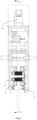
FIG. 1 is a structure diagram of some embodiments of a wood-plastic/lumber composite co-extrusion feeder, which is not claimed independently from the claimed method; -
FIG. 2 is a top view of some embodiments of the wood-plastic/lumber composite co-extrusion feeder; and -
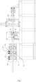
FIG. 3 is a cross-section view in a direction A-A ofFIG. 2 . - The concept, the specific structure and the generated technical effect of the present invention are clearly and completely described hereinafter with reference to the embodiments and the accompanying drawings to fully understand the objectives, the features and the effects of the present invention. Obviously, the described embodiments are only some but not all of the embodiments of the present invention, and based on the embodiments of the present invention, other embodiments obtained by those skilled in the art without going through any creative work all belong to the scope of protection of the present invention. In addition, all coupling/connection relationships mentioned therein do not indicate direct connection between members only, but indicate that a better coupling structure may be formed by adding or reducing a coupling accessory according to specific implementation conditions.
- With reference to
FIG 1 to FIG. 3 , a wood-plastic/lumber composite co-extrusion feeder includes aframe 10. At least one group of toothed conveying units 6, a toothmark milling unit 8 for milling tooth marks on an outer surface of a lumber, and a lumber co-extrusion mold 9 are arranged on theframe 10 in sequence. Each toothed conveying unit 6 includes a lowertoothed pressure roller 61 installed on a first fixed bearing seat and an uppertoothed pressure roller 60 installed on a first movable bearing seat, and after the first fixed bearing seat and the first movable bearing seat are connected by an adjustment unit, a first conveying channel having an adjustable height is formed between the uppertoothed pressure roller 60 and the lower-toothed pressure roller 61. Theframe 10 is further provided with a speed regulating motor 2, at an output end of the speed regulating motor 2, a speed reducer 3 is installed and connected with the toothed conveying unit 6 and a rubber pressure roller unit 5 by achain drive 4. - The speed regulating motor 2 and the speed reducer 3 control a speed at which the lumber enters the mold by the chain drive, and the rubber pressure roller unit 5 controls an irregular error when the lumber enters initially. The toothed conveying unit 6 accurately controls a forward speed of the lumber and offsets a reverse resistance generated during operation of the milling cutter set in the tooth
mark milling unit 8, and the two groups of limiting rubber roller sets define and maintain a forward linear position of the lumber. The lumber is milled into a precise-sized lumber by the milling cutter on a fine tooth mark milling machine and the tooth marks are pressed thereon, and then the lumber enters the wood-plastic/lumber composite co-extrusion mold 9. - Hard alloy sharp teeth are densely distributed on the upper
toothed pressure roller 60 and the lowertoothed pressure roller 61, and bite into the surface of the lumber, so as to accurately control the forward speed of the lumber and offset the reverse resistance generated during operation of the milling cutter set in the toothmark milling unit 8. By replacing the middle fixed-length sleeve, it is suitable for the lumbers with different size requirements. A compressed spring and an adjusting nut are used for maintaining a pressure of the uppertoothed pressure roller 60. - At a front side of the toothed conveying unit 6, a rubber pressure roller unit 5 is arranged which includes a
lower rubber roller 51 installed on a second fixed bearing seat and anupper rubber roller 50 installed on a second movable bearing seat. After the second fixed bearing seat and the second movable bearing seat are connected by an adjustment unit, a second conveying channel having an adjustable height is formed between theupper rubber roller 50 and thelower rubber roller 51, and an elastic rubber layer is sheathed on outer surfaces of theupper rubber roller 50 and thelower rubber roller 51. Theupper rubber roller 50 and thelower rubber roller 51 have a large friction force and a corresponding elasticity, thus being able to adapt to the irregular error when the lumber enters initially. By replacing the middle fixed-length sleeve, it is suitable for the lumbers with different size requirements. The compressed spring and the adjusting nut are used for maintaining the pressure of theupper rubber roller 50. - The adjustment unit includes a sliding rod, a fixed-length sleeve sheathed outside the sliding rod, an adjusting
nut 63 for adjustment and acompressed spring 62 with one end pressed against the adjustingnut 63. One end of the adjustingnut 63 is respectively inserted into a corresponding movable bearing seat, one end of thecompressed spring 62 is pressed against the corresponding movable bearing seat, and the other end of thecompressed spring 62 is pressed against the adjustingnut 63. - Each toothed conveying unit 6 is provided with a group of limiting rubber roller sets 7, each limiting rubber roller set 7 includes two holding brackets, a left limiting rubber roller and a right limiting rubber roller, and a plurality of bearing seats are arranged on each holding bracket. The left limiting rubber roller and the right limiting rubber roller are installed between two bearing seats of the corresponding holding brackets. A limiting space is formed between the left limiting rubber roller and the right limiting rubber roller.
- Two toothed conveying units 6 are provided, and the two toothed conveying units 6 are located between two groups of limiting rubber roller sets 7, which means that the two groups of limiting rubber roller sets 7 are installed at two sides of two groups of toothed conveying units 6 to limit and maintain the forward linear position of the lumber. The left limiting rubber roller and the right limiting rubber roller have a corresponding elasticity, thus being able to adapt to the irregular error when the lumber enters initially.
- The tooth
mark milling unit 8 includes a first tooth mark milling mechanism for milling upper and lower surfaces of a lumber and a second tooth mark milling mechanism for milling left and right surfaces of the lumber. The first tooth mark milling mechanism includes a first milling cutter frame and a firsttooth mark roller 81 located at a rear side of the first milling cutter frame, the second tooth mark milling mechanism includes a second milling cutter frame and a secondtooth mark roller 82 located at a rear side of the second milling cutter frame, and the first milling cutter frame and the second milling cutter frame are respectively provided with a milling cutter. The first tooth mark milling mechanism and the second tooth mark milling mechanism are respectively provided with a high-speed milling cutter motor. - In the embodiment, the first tooth mark milling mechanism is located at a front side of the second tooth mark milling mechanism. After the lumber passes through the first tooth mark milling mechanism and the second tooth mark milling mechanism in sequence, and the corresponding milling cutters respectively process the upper and lower surfaces and the left and right surfaces of the lumber, the lumber is milled into the precise-sized lumber, and the tooth marks are pressed on the corresponding surfaces of the lumber by the first
tooth mark roller 81 and the secondtooth mark roller 82. The lumber enters the wood-plastic/lumber composite co-extrusion mold 9, and the tooth marks on the precise-sized lumber form an anchor chain effect with wood-plastic composite melt in the co-extrusion mold, thus increasing an interface bonding strength. - A method for manufacturing a wood-plastic coated lumber composite, which includes the following steps:
- 1) feeding a lumber core by the wood-plastic/lumber composite co-extrusion feeder as described above and processing the lumber core to form point-like gear pressing marks on the lumber core;
- 2) weaving or winding a continuous high-strength fiber on a surface of the lumber core to form a fiber mesh; and
- 3) co-extruding outside the fiber mesh to form a wood-plastic layer to obtain a wood-plastic coated lumber composite.
- In some embodiments of the manufacturing method, the wood-plastic coated lumber composite includes the lumber core, the lumber core is coated with a wood-plastic composite layer, and the surface of the lumber core is provided with the point-like gear pressing marks. The continuous fiber mesh is also coated outside the lumber core with the point-like gear pressing marks, and the fiber mesh is coated and restrained by the wood-plastic composite layer.
- The high-strength fiber is at least one of a carbon fiber, a glass fiber, a basalt fiber, an aramid fiber, a polyester fiber, a polyamide fiber and a polyacrylonitrile fiber.
- In some embodiments of the manufacturing method, the high-strength fiber is a fiber pre-soaked with a prepreg resin matrix, and the prepreg resin matrix is at least one of a wood-plastic composite or polypropylene, polyethylene, polyvinyl chloride, polylactic acid and polystyrene.
- In some embodiments of the manufacturing method, the wood-plastic composite layer includes a first wood-plastic layer and a second wood-plastic layer which are connected, wherein the first wood-plastic layer is completely coated on the lumber core and the point-like gear pressing marks and forms a nail structure in the point-like gear pressing marks, the continuous fiber mesh is arranged between the first wood-plastic layer and the second wood-plastic layer, and the second wood-plastic layer is completely coated on the fiber mesh.
- In some embodiments of the manufacturing method, a pressing mark depth is 0.5 mm to 4 mm independently; and a pressing mark density is 1 piece/cm2 to 20 pieces/cm2 independently, and is preferably 4 pieces/cm2 to 10 pieces/cm2.
- In some embodiments of the manufacturing method, thicknesses of the first wood-plastic layer and the second wood-plastic layer are 0.1 mm to 2 mm and 1 mm to 5 mm respectively.
- A raw material for the wood-plastic composite includes all wood fiber materials and mixtures thereof, and a thermoplastic polymer, such as PP\PE\PVC\PS\polylactic acid and a blend of the mixtures thereof. For convenience of comparison, in the following embodiments and comparative embodiments, the wood-plastic composite consists of 40% (mass fraction) wood powder, 50t% (mass fraction) high-density polyethylene, 5 % talcum powder, 3 % coupling agent and 2 % lubricant.
- A wood-plastic coated lumber composite includes a lumber core. A cross section of the lumber core is 74 mm×34 mm. A surface of the lumber core is provided with point-like gear pressing marks with a depth of 2 mm and a density of 10 pieces/cm2. A continuous fiber mesh is further coated outside the lumber core, and the fiber mesh is coated and restrained by the wood-plastic composite layer.
- The fiber mesh is formed by weaving or winding a continuous carbon fiber outside the lumber core.
- The wood-plastic composite layer is coated on the lumber core and the fiber mesh in a co-extruded manner, wherein the wood-plastic composite layer includes a first wood-plastic layer and a second wood-plastic layer. The first wood-plastic layer has a thickness of 1 mm, and the second wood-plastic layer has a thickness of 2 mm. The first wood-plastic layer is completely coated on the lumber core and the point-like gear pressing marks and forms a nail structure in the point-like gear pressing marks. The continuous fiber mesh is arranged between the first wood-plastic layer and the second wood-plastic layer, and the second wood-plastic layer is completely coated on the fiber mesh.
- The Embodiment 2 is the same as the Embodiment 1, except that the carbon fiber is pre-soaked with the wood-plastic composite.
- The Embodiment 3 is the same as the Embodiment 1, except that the pressing mark depth is 4 mm.
- The
Embodiment 4 is the same as the Embodiment 1, except that the pressing mark depth is 0.5mm. - The Embodiment 5 is the same as the Embodiment 3, except that the carbon fiber is pre-soaked with the wood-plastic composite.
- The Embodiment 6 is the same as the Embodiment 2, except that the pressing mark density is 5 pieces/cm2.
- The Embodiment 7 is the same as the Embodiment 2, except that the pressing mark density is 1 piece/cm2.
- The
Embodiment 8 is the same as the Embodiment 2, except that the pressing mark density is 25 pieces/cm2. - The Comparative Embodiment 1 is the same as the Embodiment 1, except that the pressing mark depth is 0.3mm.
- The Comparative Embodiment 2 is the same as the Embodiment 1, except that the continuous fiber mesh is not coated outside the lumber core.
- The Comparative Embodiment 3 is the same as the Embodiment 1, except that the surface of the lumber core has no pressing mark.
- The
Comparative Embodiment 4 is the same as the Embodiment 1, except that the surface of the lumber core has no pressing mark, and the continuous fiber mesh is not coated outside the lumber core.Interface bonding strength (MPa) Embodiment 1 1.07 to 1.26 Embodiment 2 1.28 to 1.59 Embodiment 3 1.21 to 1.49 Embodiment 40.51 to 0.75 Embodiment 5 1.55 to 1.91 Embodiment 6 1.11 to 1.34 Embodiment 7 0.92 to 1.10 Embodiment 81.33 to 1.67 Comparative Embodiment 1 0.42 to 0.64 Comparative Embodiment 2 0.40 to 0.61 Comparative Embodiment 3 0.33 to 0.54 Comparative Embodiment 40.22 to 0.37 - The pressing marks on the surface of the lumber core and the coated continuous fiber mesh are able to greatly improve the interface bonding strength, and the pressing mark depth has a positive correlation with the interface bonding strength within a certain range. When the pressing mark depth is higher than a certain range, the interface bonding strength is not improved significantly. The carbon fiber pre-soaked with the wood-plastic composite can better improve the interface bonding strength. Increasing the pressing mark density in a certain range is beneficial for improving the interface bonding strength.
Claims (5)
- A method for manufacturing a wood-plastic coated lumber composite, comprising the following steps:1) feeding a lumber core by a wood-plastic/lumber composite co-extrusion feeder, the wood-plastic/lumber composite co-extrusion feeder comprising a frame (10), wherein at least one group of toothed conveying units (6), a tooth mark milling unit (8) for milling tooth marks on an outer surface of a lumber, and a lumber co-extrusion mold (9) are arranged on the frame (10) in sequence, each toothed conveying unit (6) comprises a lower toothed pressure roller (61) installed on a first fixed bearing seat and an upper toothed pressure roller (60) installed on a first movable bearing seat, and after the first fixed bearing seat and the first movable bearing seat are connected by an adjustment unit, a first conveying channel having an adjustable height is formed between the upper toothed pressure roller (60) and the lower-toothed pressure roller (61), and processing the lumber core to form point-like gear pressing marks on the lumber core;2) weaving or winding a continuous high-strength fiber on a surface of the lumber core to form a fiber mesh; and3) co-extruding outside the fiber mesh to form a wood-plastic layer to obtain a wood-plastic coated lumber composite.
- The method according to claim 1, wherein the wood-plastic coated lumber composite comprises the lumber core coated with a wood-plastic composite layer, and the surface of the lumber core is provided with the point-like gear pressing marks; the continuous fiber mesh is further coated outside the lumber core with the point-like gear pressing marks, and the fiber mesh is coated and restrained by the wood-plastic composite layer; and the high-strength fiber is at least one of a carbon fiber, a glass fiber, a basalt fiber, an aramid fiber, a polyester fiber, a polyamide fiber and a polyacrylonitrile fiber.
- The method according to claim 1 or 2, wherein the high-strength fiber is a fiber pre-soaked with a prepreg resin matrix, and the prepreg resin matrix is at least one of a wood-plastic composite or polypropylene, polyethylene, polyvinyl chloride, polylactic acid and polystyrene; the wood-plastic composite layer comprises a first wood-plastic layer and a second wood-plastic layer which are connected, wherein the first wood-plastic layer is completely coated on the lumber core and the point-like gear pressing marks and forms a nail structure in the point-like gear pressing marks, the continuous fiber mesh is arranged between the first wood-plastic layer and the second wood-plastic layer, and the second wood-plastic layer is completely coated on the fiber mesh.
- The method according to claims 1 to 3, wherein a pressing mark depth is 0.5 mm to 4 mm independently; and a pressing mark density is 1 piece/cm2 to 20 pieces/cm2 independently, and is preferably 4 pieces/cm2 to 10 pieces/cm2.
- The method according to claims 1 to 4, wherein thicknesses of the first wood-plastic layer and the second wood-plastic layer are 0.1 mm to 2 mm and 1 mm to 5 mm respectively.
Applications Claiming Priority (3)
| Application Number | Priority Date | Filing Date | Title |
|---|---|---|---|
| CN201910014126.7A CN109822858B (en) | 2019-01-08 | 2019-01-08 | Wood-plastic solid wood co-extrusion feeder |
| CN201910014163.8A CN109849447B (en) | 2019-01-08 | 2019-01-08 | Wood-plastic coated solid wood composite material and preparation method thereof |
| PCT/CN2019/128960 WO2020143476A1 (en) | 2019-01-08 | 2019-12-27 | Device and method for manufacturing wood-plastic coated solid wood composite material |
Publications (4)
| Publication Number | Publication Date |
|---|---|
| EP3756853A1 EP3756853A1 (en) | 2020-12-30 |
| EP3756853A4 EP3756853A4 (en) | 2021-06-23 |
| EP3756853C0 EP3756853C0 (en) | 2023-09-06 |
| EP3756853B1 true EP3756853B1 (en) | 2023-09-06 |
Family
ID=71520226
Family Applications (1)
| Application Number | Title | Priority Date | Filing Date |
|---|---|---|---|
| EP19909157.0A Active EP3756853B1 (en) | 2019-01-08 | 2019-12-27 | Device and method for manufacturing wood-plastic coated solid wood composite material |
Country Status (4)
| Country | Link |
|---|---|
| US (1) | US11865759B2 (en) |
| EP (1) | EP3756853B1 (en) |
| JP (1) | JP7087105B2 (en) |
| WO (1) | WO2020143476A1 (en) |
Families Citing this family (5)
| Publication number | Priority date | Publication date | Assignee | Title |
|---|---|---|---|---|
| CN114311587A (en) * | 2021-12-28 | 2022-04-12 | 南通新帝克单丝科技股份有限公司 | Production device for coating and forming polymer monofilaments |
| CN114523609A (en) * | 2021-12-31 | 2022-05-24 | 安徽科居新材料科技有限公司 | Plastic-wood processing and conveying equipment with environment-friendly function and method thereof |
| TWI835321B (en) * | 2022-09-29 | 2024-03-11 | 莊承翰 | Forming method and system for rough surface of imitation wood |
| DE102022128404A1 (en) * | 2022-10-26 | 2024-05-02 | Coperion Gmbh | Modular production plant and method for designing a production plant |
| CN117052266B (en) * | 2023-08-11 | 2024-01-16 | 江西立立联新型建材有限公司 | Edge covering equipment for door leaf of plastic-wood co-extrusion type framework |
Family Cites Families (25)
| Publication number | Priority date | Publication date | Assignee | Title |
|---|---|---|---|---|
| GB190417603A (en) * | 1904-08-12 | 1905-08-12 | George Skaats Mayhew | Improvements in and relating to Fireproof Wooden-cored Plaster Slabs for Building and other purposes and in Machines for Making the same. |
| US3323172A (en) * | 1965-01-22 | 1967-06-06 | Weyerhaeuser Co | Extrusion apparatus |
| JPS5695656A (en) | 1979-12-28 | 1981-08-03 | Sekisui Chem Co Ltd | Production of three-layer construction |
| CN2275024Y (en) | 1996-12-25 | 1998-02-25 | 张君明 | Multifunction working equipment for decorative plate |
| CN2330484Y (en) * | 1998-04-29 | 1999-07-28 | 台圳木工机械(北京)有限公司 | Integrated material longitudinal connecting machine with feeding device |
| JP2004174721A (en) * | 2002-11-22 | 2004-06-24 | Iris Ohyama Inc | Woody molded product and its manufacturing method |
| US7175905B2 (en) | 2003-11-17 | 2007-02-13 | Barry James Curtis | Composite coated/encapsulated wood products and methods to produce the same |
| DE102004010873A1 (en) | 2004-03-05 | 2005-09-22 | Homag Holzbearbeitungssysteme Ag | Method and device for producing a lightweight board |
| CN1833836A (en) | 2005-03-15 | 2006-09-20 | 苏泉窝 | Two-end cutting tooth machine for woodworking in non-fixed length |
| CN200957620Y (en) | 2006-08-17 | 2007-10-10 | 刘岳法 | Multi-feeding bamboo-wooden roll-turning mill stripper |
| JP5396066B2 (en) | 2008-11-05 | 2014-01-22 | 株式会社山本鉄工所 | Wood core plastic molding and its manufacturing method |
| CN101871299A (en) | 2009-04-21 | 2010-10-27 | 无锡百沐得科技有限公司 | Pultruded bamboo glass belt fiber reinforce plastic fasting door and window special section and molding method thereof |
| CN102189575A (en) | 2010-03-09 | 2011-09-21 | 中江县宏泰木业有限责任公司 | Sawtooth forming device for wood board |
| CN102431245A (en) | 2011-09-08 | 2012-05-02 | 宁波雄歌进出口有限公司 | Plastic bamboo plate and production technology thereof |
| CN202607781U (en) | 2012-03-31 | 2012-12-19 | 漳州喜盈门家具制品有限公司 | Wood automatic butting machine |
| CN202726478U (en) | 2012-05-14 | 2013-02-13 | 廊坊开发区罗宝建筑节能材料有限公司 | Luobao plate indentation slot milling machine |
| CN103732042B (en) | 2013-12-11 | 2016-06-01 | 上海交通大学 | The constant temperature and pressure securing system of the Primary Component in particular surroundings |
| CN104210080B (en) | 2014-09-12 | 2016-09-28 | 王清文 | Solid wood composite co-extrusion modling device moulded by a kind of wood |
| CN104228236A (en) * | 2014-09-15 | 2014-12-24 | 王清文 | Wood-plastic coated solid wood composite material and preparation method thereof |
| CN106065194A (en) | 2016-06-12 | 2016-11-02 | 王海刚 | A kind of wood plastic composite of continuous lod and preparation method thereof |
| CN106113738B (en) | 2016-07-15 | 2019-01-04 | 广东新秀新材料股份有限公司 | Sandwich structure composite material and preparation method thereof |
| CN107866878A (en) | 2017-11-17 | 2018-04-03 | 成都古蜀乌木工艺品厂 | Efficient wood sheet cutter can be carried |
| CN108162094A (en) | 2018-02-26 | 2018-06-15 | 台山市新英汉装饰材料有限公司 | A kind of plank paster equipment with automatic feeding system |
| CN109849447B (en) | 2019-01-08 | 2019-12-17 | 华南农业大学 | Wood-plastic coated solid wood composite material and preparation method thereof |
| CN109822858B (en) | 2019-01-08 | 2021-05-14 | 华南农业大学 | Wood-plastic solid wood co-extrusion feeder |
-
2019
- 2019-12-27 WO PCT/CN2019/128960 patent/WO2020143476A1/en unknown
- 2019-12-27 US US17/047,344 patent/US11865759B2/en active Active
- 2019-12-27 EP EP19909157.0A patent/EP3756853B1/en active Active
- 2019-12-27 JP JP2020552788A patent/JP7087105B2/en active Active
Also Published As
| Publication number | Publication date |
|---|---|
| US20210138710A1 (en) | 2021-05-13 |
| EP3756853A1 (en) | 2020-12-30 |
| JP2021517083A (en) | 2021-07-15 |
| JP7087105B2 (en) | 2022-06-20 |
| EP3756853A4 (en) | 2021-06-23 |
| WO2020143476A1 (en) | 2020-07-16 |
| EP3756853C0 (en) | 2023-09-06 |
| US11865759B2 (en) | 2024-01-09 |
Similar Documents
| Publication | Publication Date | Title |
|---|---|---|
| EP3756853B1 (en) | Device and method for manufacturing wood-plastic coated solid wood composite material | |
| EP3170951B1 (en) | High-strength pvc sheet floor and manufacturing method therefor | |
| US7987885B2 (en) | System and die for forming a continuous filament reinforced structural plastic profile by pultrusion/coextrusion | |
| US8852475B2 (en) | Method of making continuous filament reinforced structural plastic profiles using pultrusion/coextrusion | |
| CN109849447B (en) | Wood-plastic coated solid wood composite material and preparation method thereof | |
| CN111003968A (en) | High-performance ecological stone floor and preparation process thereof | |
| WO2009152682A1 (en) | Plastics panel having fiber grid and preparation method thereof | |
| CN111038051A (en) | PVC (polyvinyl chloride) and ASA (acrylonitrile styrene acrylate) co-extruded section bar and preparation method thereof | |
| CN113771451A (en) | Multilayer coating co-extrusion profile and production method thereof | |
| EP2783850B1 (en) | Wood-fiber aluminum-plastic composite profile and producing method thereof | |
| CN102643466A (en) | Coextruded composite material applied to PE (polyethylene) wood-plastic material and relevant material and preparation method thereof | |
| CN110406222A (en) | A kind of weather-proof colored box material of foaming PVC co-extrusion and preparation method thereof | |
| EP3140098B1 (en) | Process for manufacturing panels for floor and wall coverings | |
| CN109869540B (en) | FRP strip reinforcing thermoplastic resin helical bellows | |
| CN200963892Y (en) | Device for manufacturing thermal melt composite material by plastic casting method | |
| CN105462104A (en) | PVC crusted foamed building composite batten | |
| CN202498800U (en) | Continuous fiber reinforced polypropylene foamed board | |
| CN109694535B (en) | Engineering plastic alloy composite building template and preparation method thereof | |
| CN104608395B (en) | A kind of forming method of thermoplasticity support | |
| CN109822858B (en) | Wood-plastic solid wood co-extrusion feeder | |
| CN113334881A (en) | Integrally-formed high-weather-resistance toughened mineral bamboo-wood composite co-extruded sheet and preparation method thereof | |
| CN113524839A (en) | Bidirectional reinforced PP (polypropylene) plate and preparation method thereof | |
| CN112724552A (en) | PVC-M impact-resistant pipe and preparation method thereof | |
| CN1334186A (en) | Low-foamed high-density polyethylene lath and its preparing process | |
| CN105155839A (en) | High-strength formwork free of layer separation and method for manufacturing high-strength formwork |
Legal Events
| Date | Code | Title | Description |
|---|---|---|---|
| STAA | Information on the status of an ep patent application or granted ep patent |
Free format text: STATUS: THE INTERNATIONAL PUBLICATION HAS BEEN MADE |
|
| PUAI | Public reference made under article 153(3) epc to a published international application that has entered the european phase |
Free format text: ORIGINAL CODE: 0009012 |
|
| STAA | Information on the status of an ep patent application or granted ep patent |
Free format text: STATUS: REQUEST FOR EXAMINATION WAS MADE |
|
| 17P | Request for examination filed |
Effective date: 20200924 |
|
| AK | Designated contracting states |
Kind code of ref document: A1 Designated state(s): AL AT BE BG CH CY CZ DE DK EE ES FI FR GB GR HR HU IE IS IT LI LT LU LV MC MK MT NL NO PL PT RO RS SE SI SK SM TR |
|
| AX | Request for extension of the european patent |
Extension state: BA ME |
|
| RIN1 | Information on inventor provided before grant (corrected) |
Inventor name: OU, RONGXIAN Inventor name: XU, JUNJIE Inventor name: SUN, LICHAO Inventor name: WANG, QINGWEN Inventor name: YI, XIN Inventor name: TANG, WEI |
|
| A4 | Supplementary search report drawn up and despatched |
Effective date: 20210527 |
|
| RIC1 | Information provided on ipc code assigned before grant |
Ipc: B29C 48/285 20190101AFI20210520BHEP Ipc: B29C 48/154 20190101ALI20210520BHEP Ipc: B27M 1/00 20060101ALI20210520BHEP |
|
| DAV | Request for validation of the european patent (deleted) | ||
| DAX | Request for extension of the european patent (deleted) | ||
| GRAP | Despatch of communication of intention to grant a patent |
Free format text: ORIGINAL CODE: EPIDOSNIGR1 |
|
| STAA | Information on the status of an ep patent application or granted ep patent |
Free format text: STATUS: GRANT OF PATENT IS INTENDED |
|
| INTG | Intention to grant announced |
Effective date: 20230609 |
|
| GRAS | Grant fee paid |
Free format text: ORIGINAL CODE: EPIDOSNIGR3 |
|
| GRAA | (expected) grant |
Free format text: ORIGINAL CODE: 0009210 |
|
| STAA | Information on the status of an ep patent application or granted ep patent |
Free format text: STATUS: THE PATENT HAS BEEN GRANTED |
|
| AK | Designated contracting states |
Kind code of ref document: B1 Designated state(s): AL AT BE BG CH CY CZ DE DK EE ES FI FR GB GR HR HU IE IS IT LI LT LU LV MC MK MT NL NO PL PT RO RS SE SI SK SM TR |
|
| REG | Reference to a national code |
Ref country code: GB Ref legal event code: FG4D |
|
| REG | Reference to a national code |
Ref country code: CH Ref legal event code: EP |
|
| REG | Reference to a national code |
Ref country code: IE Ref legal event code: FG4D |
|
| REG | Reference to a national code |
Ref country code: DE Ref legal event code: R096 Ref document number: 602019037158 Country of ref document: DE |
|
| U01 | Request for unitary effect filed |
Effective date: 20231002 |
|
| U07 | Unitary effect registered |
Designated state(s): AT BE BG DE DK EE FI FR IT LT LU LV MT NL PT SE SI Effective date: 20231011 |
|
| PG25 | Lapsed in a contracting state [announced via postgrant information from national office to epo] |
Ref country code: GR Free format text: LAPSE BECAUSE OF FAILURE TO SUBMIT A TRANSLATION OF THE DESCRIPTION OR TO PAY THE FEE WITHIN THE PRESCRIBED TIME-LIMIT Effective date: 20231207 |
|
| U20 | Renewal fee paid [unitary effect] |
Year of fee payment: 5 Effective date: 20231219 |
|
| PG25 | Lapsed in a contracting state [announced via postgrant information from national office to epo] |
Ref country code: RS Free format text: LAPSE BECAUSE OF FAILURE TO SUBMIT A TRANSLATION OF THE DESCRIPTION OR TO PAY THE FEE WITHIN THE PRESCRIBED TIME-LIMIT Effective date: 20230906 Ref country code: NO Free format text: LAPSE BECAUSE OF FAILURE TO SUBMIT A TRANSLATION OF THE DESCRIPTION OR TO PAY THE FEE WITHIN THE PRESCRIBED TIME-LIMIT Effective date: 20231206 Ref country code: HR Free format text: LAPSE BECAUSE OF FAILURE TO SUBMIT A TRANSLATION OF THE DESCRIPTION OR TO PAY THE FEE WITHIN THE PRESCRIBED TIME-LIMIT Effective date: 20230906 Ref country code: GR Free format text: LAPSE BECAUSE OF FAILURE TO SUBMIT A TRANSLATION OF THE DESCRIPTION OR TO PAY THE FEE WITHIN THE PRESCRIBED TIME-LIMIT Effective date: 20231207 |
|
| PG25 | Lapsed in a contracting state [announced via postgrant information from national office to epo] |
Ref country code: IS Free format text: LAPSE BECAUSE OF FAILURE TO SUBMIT A TRANSLATION OF THE DESCRIPTION OR TO PAY THE FEE WITHIN THE PRESCRIBED TIME-LIMIT Effective date: 20240106 |
|
| PG25 | Lapsed in a contracting state [announced via postgrant information from national office to epo] |
Ref country code: ES Free format text: LAPSE BECAUSE OF FAILURE TO SUBMIT A TRANSLATION OF THE DESCRIPTION OR TO PAY THE FEE WITHIN THE PRESCRIBED TIME-LIMIT Effective date: 20230906 |
|
| PG25 | Lapsed in a contracting state [announced via postgrant information from national office to epo] |
Ref country code: SM Free format text: LAPSE BECAUSE OF FAILURE TO SUBMIT A TRANSLATION OF THE DESCRIPTION OR TO PAY THE FEE WITHIN THE PRESCRIBED TIME-LIMIT Effective date: 20230906 Ref country code: RO Free format text: LAPSE BECAUSE OF FAILURE TO SUBMIT A TRANSLATION OF THE DESCRIPTION OR TO PAY THE FEE WITHIN THE PRESCRIBED TIME-LIMIT Effective date: 20230906 Ref country code: IS Free format text: LAPSE BECAUSE OF FAILURE TO SUBMIT A TRANSLATION OF THE DESCRIPTION OR TO PAY THE FEE WITHIN THE PRESCRIBED TIME-LIMIT Effective date: 20240106 Ref country code: ES Free format text: LAPSE BECAUSE OF FAILURE TO SUBMIT A TRANSLATION OF THE DESCRIPTION OR TO PAY THE FEE WITHIN THE PRESCRIBED TIME-LIMIT Effective date: 20230906 Ref country code: CZ Free format text: LAPSE BECAUSE OF FAILURE TO SUBMIT A TRANSLATION OF THE DESCRIPTION OR TO PAY THE FEE WITHIN THE PRESCRIBED TIME-LIMIT Effective date: 20230906 Ref country code: SK Free format text: LAPSE BECAUSE OF FAILURE TO SUBMIT A TRANSLATION OF THE DESCRIPTION OR TO PAY THE FEE WITHIN THE PRESCRIBED TIME-LIMIT Effective date: 20230906 |
|
| PG25 | Lapsed in a contracting state [announced via postgrant information from national office to epo] |
Ref country code: PL Free format text: LAPSE BECAUSE OF FAILURE TO SUBMIT A TRANSLATION OF THE DESCRIPTION OR TO PAY THE FEE WITHIN THE PRESCRIBED TIME-LIMIT Effective date: 20230906 |
|
| REG | Reference to a national code |
Ref country code: DE Ref legal event code: R097 Ref document number: 602019037158 Country of ref document: DE |
|
| PLBE | No opposition filed within time limit |
Free format text: ORIGINAL CODE: 0009261 |
|
| STAA | Information on the status of an ep patent application or granted ep patent |
Free format text: STATUS: NO OPPOSITION FILED WITHIN TIME LIMIT |
|
| REG | Reference to a national code |
Ref country code: CH Ref legal event code: PL |
|
| 26N | No opposition filed |
Effective date: 20240607 |
|
| PG25 | Lapsed in a contracting state [announced via postgrant information from national office to epo] |
Ref country code: MC Free format text: LAPSE BECAUSE OF FAILURE TO SUBMIT A TRANSLATION OF THE DESCRIPTION OR TO PAY THE FEE WITHIN THE PRESCRIBED TIME-LIMIT Effective date: 20230906 |
|
| GBPC | Gb: european patent ceased through non-payment of renewal fee |
Effective date: 20231227 |
|
| PG25 | Lapsed in a contracting state [announced via postgrant information from national office to epo] |
Ref country code: MC Free format text: LAPSE BECAUSE OF FAILURE TO SUBMIT A TRANSLATION OF THE DESCRIPTION OR TO PAY THE FEE WITHIN THE PRESCRIBED TIME-LIMIT Effective date: 20230906 |