EP3755854B1 - Window with lighting unit - Google Patents
Window with lighting unit Download PDFInfo
- Publication number
- EP3755854B1 EP3755854B1 EP19706925.5A EP19706925A EP3755854B1 EP 3755854 B1 EP3755854 B1 EP 3755854B1 EP 19706925 A EP19706925 A EP 19706925A EP 3755854 B1 EP3755854 B1 EP 3755854B1
- Authority
- EP
- European Patent Office
- Prior art keywords
- window
- handle
- window pane
- lighting unit
- degrees
- Prior art date
- Legal status (The legal status is an assumption and is not a legal conclusion. Google has not performed a legal analysis and makes no representation as to the accuracy of the status listed.)
- Active
Links
Images

Classifications
-
- F—MECHANICAL ENGINEERING; LIGHTING; HEATING; WEAPONS; BLASTING
- F21—LIGHTING
- F21V—FUNCTIONAL FEATURES OR DETAILS OF LIGHTING DEVICES OR SYSTEMS THEREOF; STRUCTURAL COMBINATIONS OF LIGHTING DEVICES WITH OTHER ARTICLES, NOT OTHERWISE PROVIDED FOR
- F21V33/00—Structural combinations of lighting devices with other articles, not otherwise provided for
- F21V33/006—General building constructions or finishing work for buildings, e.g. roofs, gutters, stairs or floors; Garden equipment; Sunshades or parasols
-
- E—FIXED CONSTRUCTIONS
- E06—DOORS, WINDOWS, SHUTTERS, OR ROLLER BLINDS IN GENERAL; LADDERS
- E06B—FIXED OR MOVABLE CLOSURES FOR OPENINGS IN BUILDINGS, VEHICLES, FENCES OR LIKE ENCLOSURES IN GENERAL, e.g. DOORS, WINDOWS, BLINDS, GATES
- E06B7/00—Special arrangements or measures in connection with doors or windows
- E06B7/28—Other arrangements on doors or windows, e.g. door-plates, windows adapted to carry plants, hooks for window cleaners
-
- F—MECHANICAL ENGINEERING; LIGHTING; HEATING; WEAPONS; BLASTING
- F21—LIGHTING
- F21V—FUNCTIONAL FEATURES OR DETAILS OF LIGHTING DEVICES OR SYSTEMS THEREOF; STRUCTURAL COMBINATIONS OF LIGHTING DEVICES WITH OTHER ARTICLES, NOT OTHERWISE PROVIDED FOR
- F21V23/00—Arrangement of electric circuit elements in or on lighting devices
- F21V23/04—Arrangement of electric circuit elements in or on lighting devices the elements being switches
- F21V23/0442—Arrangement of electric circuit elements in or on lighting devices the elements being switches activated by means of a sensor, e.g. motion or photodetectors
- F21V23/0464—Arrangement of electric circuit elements in or on lighting devices the elements being switches activated by means of a sensor, e.g. motion or photodetectors the sensor sensing the level of ambient illumination, e.g. dawn or dusk sensors
-
- F—MECHANICAL ENGINEERING; LIGHTING; HEATING; WEAPONS; BLASTING
- F21—LIGHTING
- F21V—FUNCTIONAL FEATURES OR DETAILS OF LIGHTING DEVICES OR SYSTEMS THEREOF; STRUCTURAL COMBINATIONS OF LIGHTING DEVICES WITH OTHER ARTICLES, NOT OTHERWISE PROVIDED FOR
- F21V23/00—Arrangement of electric circuit elements in or on lighting devices
- F21V23/04—Arrangement of electric circuit elements in or on lighting devices the elements being switches
- F21V23/0442—Arrangement of electric circuit elements in or on lighting devices the elements being switches activated by means of a sensor, e.g. motion or photodetectors
- F21V23/0471—Arrangement of electric circuit elements in or on lighting devices the elements being switches activated by means of a sensor, e.g. motion or photodetectors the sensor detecting the proximity, the presence or the movement of an object or a person
-
- E—FIXED CONSTRUCTIONS
- E04—BUILDING
- E04D—ROOF COVERINGS; SKY-LIGHTS; GUTTERS; ROOF-WORKING TOOLS
- E04D13/00—Special arrangements or devices in connection with roof coverings; Protection against birds; Roof drainage; Sky-lights
- E04D13/03—Sky-lights; Domes; Ventilating sky-lights
- E04D13/033—Sky-lights; Domes; Ventilating sky-lights provided with means for controlling the light-transmission or the heat-reflection, (e.g. shields, reflectors, cleaning devices)
-
- E—FIXED CONSTRUCTIONS
- E04—BUILDING
- E04D—ROOF COVERINGS; SKY-LIGHTS; GUTTERS; ROOF-WORKING TOOLS
- E04D13/00—Special arrangements or devices in connection with roof coverings; Protection against birds; Roof drainage; Sky-lights
- E04D13/03—Sky-lights; Domes; Ventilating sky-lights
- E04D13/035—Sky-lights; Domes; Ventilating sky-lights characterised by having movable parts
- E04D13/0351—Sky-lights; Domes; Ventilating sky-lights characterised by having movable parts the parts pivoting about a fixed axis
- E04D13/0354—Sky-lights; Domes; Ventilating sky-lights characterised by having movable parts the parts pivoting about a fixed axis the parts being flat
-
- F—MECHANICAL ENGINEERING; LIGHTING; HEATING; WEAPONS; BLASTING
- F21—LIGHTING
- F21S—NON-PORTABLE LIGHTING DEVICES; SYSTEMS THEREOF; VEHICLE LIGHTING DEVICES SPECIALLY ADAPTED FOR VEHICLE EXTERIORS
- F21S19/00—Lighting devices or systems employing combinations of electric and non-electric light sources; Replacing or exchanging electric light sources with non-electric light sources or vice versa
- F21S19/005—Combining sunlight and electric light sources for indoor illumination
Definitions
- This invention relates to windows, and in particular windows with integrated lighting units.
- Roof windows for slanted roofs
- skylights for flat roofs
- window blinds and screening devices are used to reflect indoor light at night. If the window blinds are not in use or not installed the light is lost through the window and the window appears black. If there are window blinds, they mask the dark appearance of the window pane, but they also appear dark themselves, and of course they do not function as a light source.
- the darkness of a roof window during night time, and the desire for a window to function as a source of light, may be solved by providing artificial lighting at the window.
- direct artificial lighting such as a visible light source mounted on the window frame providing light outwardly from the window, would be very uncomfortable and glary. This is because a window is usually positioned in the field of view (such that one can have a view to the outside). Thus, there would typically be a direct view of the light source.
- Indirect lighting of the window or a blind over the window and the window cove would be preferable, by directing light towards the window.
- an indirect light source is mounted directly on the window frame, the lighting effect of the resulting very shallow angle light (known as grazing light) on the window pane or window blind is rather unattractive. For example, this grazing light reveals all ripples and defects in the window blind.
- DE202010000087U discloses a light-emitting unit which can be used as a handle.
- the light-emitting unit has a hollow body that forms the part of the handle that can be fastened with one or more foot parts to a door, a drawer or a window, such that the hollow body is located at a distance from the door, drawer or window.
- LEDs are provided within the hollow body in such a way that each LED is flush with an opening in the hollow body.
- a power source such as a battery, and a switch, for operating the LEDs.
- a window comprising:
- This window includes a lighting unit mounted on, or integrated in, a bar handle used for opening the window. It projects light onto the window pane or onto a blind over the window pane so that in dark outside conditions, the black window pane appearance or dark blind appearance is avoided. This is of particular interest for non-vertical windows, such as roof windows. By providing lighting from a raised platform, a more uniform lighting effect is possible, and glare is more easily prevented.
- the lighting unit typically comprises an LED array.
- the light is designed to give the best reflection while avoiding glare.
- the light output is generally parallel to the window pane to ensure total internal reflection of the light provided to the window pane (for example off the rear face of the pane).
- the principal output direction is the direction within an overall output beam in which the intensity is highest. Thus, it may be considered to the general output direction of the beam.
- the principal output direction may be a plane.
- the handle bar for example extends by more than 60 % along the first edge (i.e. more than 60 % of the width of the window pane), preferably more than 80 %, and most preferably more than 90 % including up to 100 %, to enable a uniform illumination of the window.
- the handle may be spaced from the first edge by 1 cm to 20 cm, for example by 5 cm to 10 cm. In other words, the perpendicular distance between the handle and the window pane may be in the range of 1 cm to 20, for example in the range of 5 cm to 10 cm.
- the handle may have a front face that when in the closed position is substantially parallel to the window pane.
- the handle may have at least one pivot that is parallel to the lower edge of the handle bar. To open the window, a user grips the handle bar and pulls in a downwards direction. This action will rotate the handle bar about the at least one pivot and the front face that was previously substantially parallel to the window pane (in the closed position) will be at an acute angle to the window pane.
- the handle position provides sufficient spacing from the window to enable an output beam to provide illumination of the full window pane with sufficient uniformity to provide an aesthetically pleasing appearance.
- the lighting unit for example has an output beam with a half width half maximum on a side facing the window pane of less than 10 degrees.
- This half width maximum is preferably less than 5 degrees, and even more preferably less than 4 degrees such as for example 3 degrees. The narrower the angle, the better the reflection properties.
- the lighting unit may deliver a symmetric output (i.e. with the same half width half maximum on both opposite sides) or it may deliver an asymmetric output.
- the lighting unit may have an output beam with a half width half maximum on a side facing away from the window pane in the range 3 to 45 degrees.
- the lighting unit has an output beam with a half width half maximum on a side facing the window pane of less than 10 degrees and a half width half maximum on a side facing away from the window pane in the range 15 to 45 degrees.
- This asymmetric beam profile illuminates the window uniformly without inducing glare in the room, as well as provided good illumination in the room.
- the lighting unit may generate general lighting.
- the lighting unit may be used to provide different lighting functions towards the window pane and away from the window pane.
- the lighting unit output may have a principal output direction of the output beam which is directed from the lighting unit to a second edge of the inner frame, the second edge being opposite to the first edge. This ensures that the full area of the window pane is illuminated.
- the lighting unit may have an output beam with a cut-off angle with respect to the principal output direction of less than 70 degrees in the direction away from the window pane.
- the lighting unit may be used to generate a polarized light output such as an S-polarized light output.
- An S-polarized light output maybe used to result in more efficient reflection from a glass window pane.
- the window pane may comprise a reflective polarizer. This may further enhance the efficiency of the reflection. Any polarization may be used to match a corresponding polarization of the light output.
- the window may further comprise blinds or curtains to be illuminated by the lighting unit.
- Such blinds may be on the outside of the window or on the inside of the window.
- the lighting unit may for example be programmed to switch on or off upon closing/opening of the blinds or curtains.
- the lighting unit may for example adjust the color of the light to the color of the window blind fabric. For example, a blue window blind could be illuminated with more bluish light to enhance the color and save energy by reducing the absorption by the blind.
- the window may further comprise:
- the lighting unit may be operated only when needed, i.e. in the dark and when a person is present.
- the ambient light detection may be performed inside and/or outside the building in which the window is installed.
- the window may further comprise:
- the lighting unit may for example be turned off when the window is open, because the light may then be directed outwardly.
- the lighting unit may have an adjustable beam shape. This may be used to adapt the lighting unit output to different sizes of window and different roof angles, for example.
- the beam shape maybe controlled electronically or mechanically (e.g. by selecting suitable optics manually).
- the window typically comprises a roof window, for example for mounting at an angle of between 30 and 60 degrees to the vertical.
- the lighting unit design preferably takes into account the intended angle of the window.
- the optical configuration is preferably optimized for such roof windows.
- the invention also provides a handle for attachment to a window, wherein the window comprises a window frame and a window pane, and wherein the handle comprises:
- This aspect provides a window handle which may be a retrofit part to an existing window (for example with an existing electrical supply).
- the handle may be:
- the illuminated handle may thus be applied to a window which does not open, and thus functions only as a dummy window handle.
- the invention also provides a method of lighting an area of a window pane, comprising: providing illumination towards the area of the window pane from a handle , wherein the handle extends along one edge of a frame which surrounds the area of the window pane, wherein the handle is spaced at a perpendicular distance from the window pane, and wherein the illumination has a principal output direction which is within 20 degrees of a plane parallel to the area of the window pane, preferably within 10 degrees.
- the window pane area may have blinds or curtains, or it may be a bare glass pane.
- the spaced handle bar may be for opening the window or it may be a dummy handle.
- the invention provides a window in which a lighting unit is provided along a bar handle for use in opening the window or provided as a dummy handle.
- the lighting unit is for illuminating the window pane or blinds over the window pane, for example when it is dark outside.
- roof windows e.g. skylights
- the lighting prevents the dark appearance of the window pane or blinds, and also partially simulates a daylight condition by giving the impression of light coming through the window.
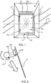
- Figure 1 shows an example of the type of window to which the invention may be applied.
- the window 10 is mounted at the base of a cove 12 and comprises a window pane 14, an inner frame 16 around the window pane and an outer frame 18.
- the outer frame is mounted to a surrounding structure such as a roof.
- the inner frame 16 may be opened and closed within the outer frame 18.
- the inner frame 16 for example pivots about an axis 20 which is horizontal when the window is installed.
- the inner frame has top and bottom cross piece edges 16a, 16b and side edges 16c, 16d.
- the outer frame also has corresponding edges.
- a rectangular window is defined.
- a handle 22 is provided in the form of a bar extending along one edge of the inner frame, in particular the top cross piece edge 16a.
- the handle may be rotated first between a fully closed position and a venting position, and then it may be rotated further into a position in which the inner frame can be pivoted open about the axis 20.
- the handle for example comprises a raised bar, spaced from the window frame by a base, such that a user may grip around the raised bar, and the raised bar and the base rotate as a single unit around a pivot (not shown) which is parallel to the axis 20.
- a lighting unit is provided along the handle 22 for providing illumination towards the window pane 14.
- the lighting unit is not visible in Figure 1 .
- the handle and its lighting unit preferably extend across the full width of the window pane. However, more generally, the lighting unit preferably extends more than 60 % of the way across the window frame edge, preferably more than 80 %, most preferably more than 90 %.
- the lighting unit may extend the full length of the handle (but the handle may itself be shorter than the full window frame width) or the handle may extend across the full width, but the lighting unit may be shorter.
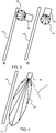
- Figure 2 shows a vertical cross section perpendicular to the plane of the window pane. It shows the handle 22 in side view with a bar 22a spaced above a base 22b and shows the lighting unit 30 which directs a light output 32 towards the window pane 14.
- the user grips the bar 22a to rotate the handle (i.e. both the bar 22a and the base 22b) and open the window.
- the handle rotates about a pivot axis 22c which is parallel with the length of the handle (i.e. parallel with the window axis 20).
- the angle of the light output 32 may change relative to the window pane 14 due to the rotation of the handle 22.
- an indirect light source is desired, and it should be placed at a distance from the window.
- the use of the handle prevents the light source providing an additional unwanted protrusion which could otherwise block daylight and/or be in the way when opening the window.
- the handle bar is positioned close to or at the edge of the inner frame and is spaced at a perpendicular distance D from the window pane as shown in Figure 2 .
- the distance D is for example in the range of 1 cm to 20 cm and typically in the range of 5 cm to 10 cm.
- the lighting may be used to illuminate a bare window pane, or there may be blinds or curtains over the window. Blinds maybe outside the window or inside the window. In the case of a double glazed window 10, the blinds maybe between the window panes.
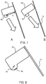
- Figure 3 shows a first set of two options.
- the light source 30 faces the window pane and has a Lambertian diffuse output beam 33. This results in a concentrated bright area close to the handle bar but does have the advantage of no direct view of the light source for the viewer.
- the light source 30 directs light parallel to the window pane and again has a Lambertian diffuse output beam 33. This results in more uniform illumination of the window pane but there is a direct view of the light source which gives rise to glare for the viewer.
- Figure 4 shows one example of a more preferred type of arrangement.
- the light source 30 generates a narrow beam 33, typically with a half width half maximum (HWHM) below 10 degrees on each side of a principal light output direction 41 of an output beam, namely a direction of peak intensity.
- HWHM half width half maximum
- the principal light output direction is for example at an angle with respect to the window pane which is in the range of 0 to 20 degrees, typically in the range of 0 to 10 degrees.
- the light is directed parallel or nearly parallel to the window pane.
- the principal light output direction 41 is offset to the parallel, it is directed towards the opposite (bottom) end of the window pane.
- the beam has a generally constant shape at different cross sections along the length of the handle bar.
- the principal light output direction 41 in fact defines a plane.
- the handle bar maybe spaced from the window pane at a perpendicular distance D in the range of 1 cm to 20 cm
- the height of the window i.e. the distance between the cross piece edges 16a, 16b
- the height of the window is for example in the range of 50 cm to 180 cm.
- an angle of 21.8 degrees is needed to direct the beam to the bottom edge. This is the reason for a possible maximum angle of 20 degrees.
- a larger window i.e. a window with a height larger than 50 cm
- a smaller protrusion distance i.e. a perpendicular distance D smaller than 20 cm
- an angle of 9.5 degrees is needed to direct the beam to the bottom edge. This is why the possible maximum angle is preferably 10 degrees.
- the width of the window, and hence the length of the handle and lighting unit, is for example in the range 30 cm to 100 cm.
- the cut-off angle of the beam is another important characteristic of the light output. For example, it is desired to define a direction (line 40 in Figure 4 ) beyond which there is no direct light from the lighting unit, in order to avoid direct glare for the viewer.
- This line 40 is preferably oriented less than 40 degrees with respect to the vertical direction, and more preferably less than 30 degrees. In this way, downward light is provided rather than shallow (horizontal) light, thereby to reduce glare.
- Figure 4 provides unobtrusive, efficient indirect internal lighting from the window surface. It may be used with a window having blinds or even when window blinds are not in use by providing improved light reflection from a standard glass window pane.
- the arrangement of Figure 4 shows a symmetric light output.
- the symmetry is each side of the principal light output direction.
- the lighting unit is preferably formed as a line of LEDs so that these principal light output directions together define a plane which represents the general light output and may be considered to be a principal light output plane of an output beam.
- One side of the plane faces the window pane and the other side of the plane faces away from the window pane.
- the light output shape is generally the same on these two sides of the principal light output plane, i.e. symmetrical around the longest central arrow 41.
- Figure 5 shows an asymmetrical arrangement.
- the principal light output direction (or plane) is shown as line (or plane) 50.
- the output beam angle is smaller on the side of the window pane, and larger on the opposite side.
- the lighting unit has an output beam 33 with a half width half maximum on the side facing the window pane of less than 10 degrees (for example in the range 3 to 10 degrees, such as 5 degrees) whereas the output beam may have with a half width half maximum on the side facing away from the window pane anywhere in the range 3 to 45 degrees.
- the narrow beam on the window pane side creates an even light distribution.
- the wider beam away from the window pane for example illuminates the window cove, or the floor beneath the window.
- the cut-off (shown by line 40) is preferably below 40 degrees offset from the vertical.
- a roof angle is typically in the range 30 to 60 degrees, and for a 30 degree roof angle, this 40 degree limit translates to at most 70 degrees from the plane of the window pane.
- angle ⁇ is less than 70 degrees.
- the angle ⁇ (at which there is a cutoff) is more than 10 degrees, for example more than 20 degrees, for example more than 30 degrees, for example more than 40 degrees.
- a further option is to use a polarized light source which emits polarized light (with the plane of incidence defined as perpendicular to the plane of the window pane).
- a polarized light source which emits polarized light (with the plane of incidence defined as perpendicular to the plane of the window pane).
- S-polarized light provides more reflection from a glass window pane than P-polarized light at the lower angles of incidence (typically most light will reflect at angles beyond 45 degrees). This can further improve the efficiency of the reflection from the window pane.
- Figure 6 shows the reflection coefficient (%, y-axis) versus the angle of incidence (degrees, x-axis) for S-polarized light as plot 60 and P polarized light as plot 62. It shows the reflection from only one air to glass interface. For a double glazed window, there are two such interfaces and two glasses to air interfaces as well, which greatly increases the total reflection value.
- the line 64 represents Brewster's angle of total transmission of the P polarized light (through the air to glass interface).
- the window pane (or blinds which are used over the window pane) may comprise a reflective polarizer to reflect the (polarized) light.
- This output polarization and polarization reflection function may be implemented with any type of polarization.
- the light distribution can also be optimized for the handle bar position which is most used by end users.
- the handle may have a rotated ventilation position, and this may be the most often used position.
- Figure 7A shows a fully closed position and Figure 7B shows a venting position with the handle rotated, but the window still closed (and secure).
- the handle for example comprise a pair of parallel spaced bars as shown in Figure 2 .
- One of these bars is to be held by the user and the gap between the bars provides space for the user's fingers.
- This is for example the most common arrangement for a Velux (Trade Mark) window design.
- the overall handle assembly is represented in Figure 7 as a single block 22.
- the two window positions shown in Figure 7 are the most likely ones for which illumination is desired. It is less likely to be desired when the window is open.
- the handle bar or the lighting unit may be rotatable so that, between the two window settings shown in Figure 7 , the lighting unit can be rotated so that the principal light output direction remains the same.
- One lighting configuration may be used when the ventilation opening is closed, and the other lighting configuration may be used when the ventilation opening is opened.
- Figure 8 shows that the lighting unit 30 maybe integrated into the body of the handle 22, for example with output optics 80.
- the same lighting unit may be used to illuminate the handle bar itself.
- the bar By making the material of the handle bar slightly transparent, the bar can light up in the dark. This guides the eye in the case of full darkness in order to find the handle bar more easily or it may be used as an indicator light to show that the ventilation function is used.
- the handle bar may have a second, diffuse source aimed at the window to provide a subtle glow around the handle bar.
- the embedded lighting function may be combined with an absence/presence detector and/or a light sensor embedded in the handle bar or in another part of the window frame. This can help to reduce the energy usage. For example, based on both the sensor and detector signals, the lighting unit may only be actuated when both the ambient light level in the room is sufficiently low and the absence/presence detector detects presence in the room.
- Figure 5 shows the components required for this variation. It shows a presence detection unit 52, an ambient light detection unit 54 and a controller 56 for controlling the lighting unit in dependence on the ambient light detection and presence detection.
- the lighting unit may be switched off when the window is opened since in that case the light will be directed outwards.
- a straightforward detection method can be used to detect that the window is opened and consequently the lighting unit will be switched off.
- Figure 5 also shows an open or closed detection unit 58 for detecting if the inner frame is open or closed and providing the detection signal to the controller 56.
- a sensor 59 may also detect the angle of the window and in response provide a different lighting setting.
- a further example is for the lighting to be programmed to switch on or off upon closing/opening the blinds or curtains.
- the open or closed detection unit 58 may additionally detect the state of the blinds or curtains.
- the lighting may also be adjusted in color as a function of the color of the window blind fabric to enhance the color and save energy by reducing the absorption by the blind.
- the examples above are based on a static fixed light output.
- the roof angle, window size, window angle (open or closed), the handle bar design, and the window settings (such as the closed setting, ventilation setting and open setting) will differ for different window type and building types.
- the beam shape may be made adjustable so that a single design is suitable for different window designs and different installations. Adjustments may be made to the direction of peak intensity (i.e. the principal light output direction as discussed above) depending on the orientation of the handle bar and/or the orientation of the window.
- the width of the beam (or the two widths in case of an asymmetric beam) may be made adjustable, and it may also be possible to set the direction of the glare cut-off angle, depending on the roof angle, window orientation and handle bar orientation.
- These adjustments may for example be made mechanically by replacing, rotating or sliding optical elements such as lenses or reflectors or blocking shields with respect to the source. This may be manual, or motor driven. Instead, electronic adjustments may be made by controlling the brightness of individually controllable light sources within the lighting unit, with those light sources having different intensity profiles.
- the adjustments can be made by the user or automatically based on sensor input, for example based on sensing the direction of gravity, the rotation angles of the window hinges etc.
- the adjustment to the beam shape for example may comprise a rotation or zoom function to give beam broadening or narrowing of the whole beam, or it may involve providing adjustment of only one of the light output characteristics such as the peak intensity direction, beam width or cut-off angle.
- the lighting unit may have a controllable output color, for example so that color temperature adjustment maybe made for applications in which artificial lighting is matched with daylight lighting conditions.
- the daylight can be measured using an external light sensor.
- the color control may be limited to a tunable white output, but full color control may also be enabled using an RGB-based LED strip.
- the LEDs themselves and their associated drivers may be entirely conventional.
- the optics needed to define the desired light output characteristics explained above may be entirely conventional.
- the lighting unit may comprise an LED strip formed as one or more rows of LED. The number and spacing of the LEDs will be selected to provide the desired overall light output and the desired lighting uniformity.
- the lighting unit (and any sensors) may be powered by a local battery (and optionally also charged by a solar panel on the roof forming part of the window installation), or else internal wiring may be provided to the window location.
- a dummy handle may be installed of the type described above, but which performs only a lighting function and does not perform an opening function.
- the handle may be provided as a part of a window, but it may also be provided as a retrofit item.
Priority Applications (1)
| Application Number | Priority Date | Filing Date | Title |
|---|---|---|---|
| PL19706925T PL3755854T3 (pl) | 2018-02-20 | 2019-02-14 | Okno z jednostką oświetleniową |
Applications Claiming Priority (2)
| Application Number | Priority Date | Filing Date | Title |
|---|---|---|---|
| EP18157681 | 2018-02-20 | ||
| PCT/EP2019/053678 WO2019162186A1 (en) | 2018-02-20 | 2019-02-14 | Window with lighting unit |
Publications (2)
| Publication Number | Publication Date |
|---|---|
| EP3755854A1 EP3755854A1 (en) | 2020-12-30 |
| EP3755854B1 true EP3755854B1 (en) | 2021-08-25 |
Family
ID=61256598
Family Applications (1)
| Application Number | Title | Priority Date | Filing Date |
|---|---|---|---|
| EP19706925.5A Active EP3755854B1 (en) | 2018-02-20 | 2019-02-14 | Window with lighting unit |
Country Status (7)
| Country | Link |
|---|---|
| US (1) | US20200393120A1 (ja) |
| EP (1) | EP3755854B1 (ja) |
| JP (1) | JP6861909B2 (ja) |
| CN (1) | CN111742106B (ja) |
| DK (1) | DK3755854T3 (ja) |
| PL (1) | PL3755854T3 (ja) |
| WO (1) | WO2019162186A1 (ja) |
Family Cites Families (33)
| Publication number | Priority date | Publication date | Assignee | Title |
|---|---|---|---|---|
| JPS4834107Y1 (ja) * | 1969-10-09 | 1973-10-16 | ||
| JPH052906A (ja) * | 1991-06-25 | 1993-01-08 | Mitsubishi Electric Corp | 採光窓兼用照明装置 |
| JP4063366B2 (ja) * | 1997-09-10 | 2008-03-19 | 美和ロック株式会社 | 建具用レバーハンドル |
| CN1201181C (zh) * | 1999-04-06 | 2005-05-11 | 里维奥公司 | 具有散射式及穿透式操作模式的电光窗玻璃结构 |
| DE20004468U1 (de) * | 2000-03-10 | 2000-06-15 | Tedev Gmbh Technik Design & Ve | Griff |
| CN2620814Y (zh) * | 2003-04-01 | 2004-06-16 | 北京雅新石光照明器材有限公司 | 具有前置反射器的照明灯具 |
| CN1693784A (zh) * | 2004-05-09 | 2005-11-09 | 乐金电子(天津)电器有限公司 | 窗式空气调节装置及调节方法 |
| JP2008505454A (ja) * | 2004-07-02 | 2008-02-21 | ディスカス デンタル インプレッションズ インコーポレーテッド | 反射器を有する硬化ライト |
| WO2006129268A2 (en) * | 2005-06-01 | 2006-12-07 | Koninklijke Philips Electronics N.V. | Artificial window |
| JP2007188651A (ja) * | 2006-01-11 | 2007-07-26 | Santo Kagaku:Kk | 発光棒状体およびドアハンドル |
| EA026191B1 (ru) * | 2007-08-03 | 2017-03-31 | Вкр Холдинг А/С | Стеклопакетный блок для использования в окне |
| US20090190331A1 (en) * | 2008-01-30 | 2009-07-30 | Carson Kelly Smith | Lock light |
| CN101618695A (zh) * | 2008-07-02 | 2010-01-06 | 秦志祥 | 防眩目车灯 |
| EP2335098A1 (en) * | 2008-10-09 | 2011-06-22 | Koninklijke Philips Electronics N.V. | Beam direction controlling device and light-output device |
| DE202010000087U1 (de) | 2010-01-27 | 2011-03-17 | FILTEC GmbH Filtertechnologie für die Elektronikindustrie | Leuchteinheit insbesondere für Griffe u.dgl. |
| WO2011107918A1 (en) * | 2010-03-02 | 2011-09-09 | Koninklijke Philips Electronics N.V. | System for combining exterior lighting and artificial lighting |
| CN102213379A (zh) * | 2010-04-06 | 2011-10-12 | 福建新希望光电科技有限公司 | 一种防眩光护栏灯 |
| IN2013CN00091A (ja) * | 2010-06-30 | 2015-07-03 | Laurimed Llc | |
| CN201759323U (zh) * | 2010-08-25 | 2011-03-16 | 志寰股份有限公司 | 简易式窗帘结构 |
| US20120327645A1 (en) * | 2011-06-27 | 2012-12-27 | Armi Products Corporation | Flood lamp with improved angular lighting uniformity |
| EP2565355B1 (en) * | 2011-09-01 | 2018-07-18 | VKR Holding A/S | Window assembly with snap-on handle, and a method for transporting the window assembly |
| CN102493745A (zh) * | 2011-12-30 | 2012-06-13 | 杨茂亮 | 覆窗式调光器 |
| JP2013218873A (ja) * | 2012-04-09 | 2013-10-24 | Sharp Corp | ライトガイド、発光装置、建材用構造体、ドア照明システムおよびドア |
| US9080763B2 (en) * | 2012-05-17 | 2015-07-14 | GE Lighting Solutions, LLC | Edge lit luminaires for windows |
| CN103216748B (zh) * | 2012-06-11 | 2015-07-08 | 上海隆光蜃景光电科技有限公司 | Led条状背光灯 |
| EP3006265B1 (en) * | 2013-05-29 | 2022-06-15 | TS Tech Co., Ltd. | Light-emitting part for vehicle |
| DK3039336T3 (en) * | 2013-10-14 | 2017-04-10 | Philips Lighting Holding Bv | Lighting systems |
| AU2014360947B2 (en) * | 2013-12-13 | 2018-05-17 | Mare Beheer B.V. | Venetian blind |
| JP6671342B2 (ja) * | 2014-08-14 | 2020-03-25 | シグニファイ ホールディング ビー ヴィSignify Holding B.V. | 周囲照明用の幅木照明装置 |
| CN106285433A (zh) * | 2015-05-22 | 2017-01-04 | 于水 | 百叶窗及其叶片组件 |
| US10660824B2 (en) * | 2015-08-11 | 2020-05-26 | Edmund L. Valentine | Devices, system and method to control the delivery of oral medications to ensure they are efficacious , taken as prescribed, and to avoid unwanted side effects |
| CN205327253U (zh) * | 2016-01-28 | 2016-06-22 | 王旋梅 | 一种带有伞的自行车 |
| CN107461085B (zh) * | 2017-07-31 | 2019-11-05 | 合肥初慕科技有限公司 | 一种节能环保的安防用锁具 |
-
2019
- 2019-02-14 DK DK19706925.5T patent/DK3755854T3/da active
- 2019-02-14 WO PCT/EP2019/053678 patent/WO2019162186A1/en unknown
- 2019-02-14 JP JP2020558532A patent/JP6861909B2/ja active Active
- 2019-02-14 EP EP19706925.5A patent/EP3755854B1/en active Active
- 2019-02-14 CN CN201980014203.7A patent/CN111742106B/zh active Active
- 2019-02-14 US US16/970,934 patent/US20200393120A1/en not_active Abandoned
- 2019-02-14 PL PL19706925T patent/PL3755854T3/pl unknown
Also Published As
| Publication number | Publication date |
|---|---|
| PL3755854T3 (pl) | 2022-01-10 |
| CN111742106B (zh) | 2022-01-14 |
| EP3755854A1 (en) | 2020-12-30 |
| JP6861909B2 (ja) | 2021-04-21 |
| JP2021508166A (ja) | 2021-02-25 |
| WO2019162186A1 (en) | 2019-08-29 |
| DK3755854T3 (da) | 2021-10-11 |
| CN111742106A (zh) | 2020-10-02 |
| US20200393120A1 (en) | 2020-12-17 |
Similar Documents
| Publication | Publication Date | Title |
|---|---|---|
| EP2542749B1 (en) | System for combining exterior lighting and artificial lighting | |
| CN102378846B (zh) | 借助于图像识别控制遮蔽设备 | |
| US9169690B2 (en) | Window treatment having backlighting | |
| US8482724B2 (en) | System and method for shade selection using a fabric brightness factor | |
| US10349489B2 (en) | Adaptable skylight | |
| US20080184636A1 (en) | LED illuminated glazing materials | |
| TWM504418U (zh) | 室內光線控制系統 | |
| EP3755854B1 (en) | Window with lighting unit | |
| US20110192551A1 (en) | Window blind assembly | |
| JP3616896B2 (ja) | 調光型遮光体 | |
| US6176289B1 (en) | Blind system for windows | |
| CA2674464C (en) | Mirrored element | |
| Christoffersen et al. | An experimental evaluation of daylight systems and lighting control | |
| JP2005310438A (ja) | 光制御システム | |
| CN113701088A (zh) | 一种全光谱led灯具、智能照明系统和教室光控制方法 | |
| KR20190133905A (ko) | 건축물의 차광 디스플레이 창 시스템 | |
| JP5414235B2 (ja) | 制御装置、照明装置及び制御方法 | |
| EP3677747A1 (en) | Sunshine shielding device and slat | |
| EP3563085B1 (en) | Interior lighting system | |
| CN213065773U (zh) | 一种光感应自动亮度调节式led灯 | |
| CN211008329U (zh) | 可调光照明窗 | |
| US20240071266A1 (en) | Powered retail signage assembly with consistent visibility in different lighting conditions | |
| KR100985868B1 (ko) | 차광장치를 이용한 중앙제어식 경관조명시스템 | |
| Müller et al. | Lighting design for museums | |
| KR20150001906U (ko) | 스마트형 전자커튼 |
Legal Events
| Date | Code | Title | Description |
|---|---|---|---|
| STAA | Information on the status of an ep patent application or granted ep patent |
Free format text: STATUS: UNKNOWN |
|
| STAA | Information on the status of an ep patent application or granted ep patent |
Free format text: STATUS: THE INTERNATIONAL PUBLICATION HAS BEEN MADE |
|
| PUAI | Public reference made under article 153(3) epc to a published international application that has entered the european phase |
Free format text: ORIGINAL CODE: 0009012 |
|
| STAA | Information on the status of an ep patent application or granted ep patent |
Free format text: STATUS: REQUEST FOR EXAMINATION WAS MADE |
|
| 17P | Request for examination filed |
Effective date: 20200921 |
|
| AK | Designated contracting states |
Kind code of ref document: A1 Designated state(s): AL AT BE BG CH CY CZ DE DK EE ES FI FR GB GR HR HU IE IS IT LI LT LU LV MC MK MT NL NO PL PT RO RS SE SI SK SM TR |
|
| AX | Request for extension of the european patent |
Extension state: BA ME |
|
| GRAP | Despatch of communication of intention to grant a patent |
Free format text: ORIGINAL CODE: EPIDOSNIGR1 |
|
| STAA | Information on the status of an ep patent application or granted ep patent |
Free format text: STATUS: GRANT OF PATENT IS INTENDED |
|
| DAV | Request for validation of the european patent (deleted) | ||
| DAX | Request for extension of the european patent (deleted) | ||
| INTG | Intention to grant announced |
Effective date: 20210330 |
|
| GRAS | Grant fee paid |
Free format text: ORIGINAL CODE: EPIDOSNIGR3 |
|
| GRAA | (expected) grant |
Free format text: ORIGINAL CODE: 0009210 |
|
| STAA | Information on the status of an ep patent application or granted ep patent |
Free format text: STATUS: THE PATENT HAS BEEN GRANTED |
|
| AK | Designated contracting states |
Kind code of ref document: B1 Designated state(s): AL AT BE BG CH CY CZ DE DK EE ES FI FR GB GR HR HU IE IS IT LI LT LU LV MC MK MT NL NO PL PT RO RS SE SI SK SM TR |
|
| REG | Reference to a national code |
Ref country code: CH Ref legal event code: EP |
|
| REG | Reference to a national code |
Ref country code: IE Ref legal event code: FG4D Ref country code: AT Ref legal event code: REF Ref document number: 1423946 Country of ref document: AT Kind code of ref document: T Effective date: 20210915 |
|
| REG | Reference to a national code |
Ref country code: DE Ref legal event code: R096 Ref document number: 602019007203 Country of ref document: DE |
|
| REG | Reference to a national code |
Ref country code: DK Ref legal event code: T3 Effective date: 20211005 |
|
| REG | Reference to a national code |
Ref country code: LT Ref legal event code: MG9D |
|
| REG | Reference to a national code |
Ref country code: NL Ref legal event code: MP Effective date: 20210825 |
|
| REG | Reference to a national code |
Ref country code: AT Ref legal event code: MK05 Ref document number: 1423946 Country of ref document: AT Kind code of ref document: T Effective date: 20210825 |
|
| PG25 | Lapsed in a contracting state [announced via postgrant information from national office to epo] |
Ref country code: ES Free format text: LAPSE BECAUSE OF FAILURE TO SUBMIT A TRANSLATION OF THE DESCRIPTION OR TO PAY THE FEE WITHIN THE PRESCRIBED TIME-LIMIT Effective date: 20210825 Ref country code: RS Free format text: LAPSE BECAUSE OF FAILURE TO SUBMIT A TRANSLATION OF THE DESCRIPTION OR TO PAY THE FEE WITHIN THE PRESCRIBED TIME-LIMIT Effective date: 20210825 Ref country code: SE Free format text: LAPSE BECAUSE OF FAILURE TO SUBMIT A TRANSLATION OF THE DESCRIPTION OR TO PAY THE FEE WITHIN THE PRESCRIBED TIME-LIMIT Effective date: 20210825 Ref country code: BG Free format text: LAPSE BECAUSE OF FAILURE TO SUBMIT A TRANSLATION OF THE DESCRIPTION OR TO PAY THE FEE WITHIN THE PRESCRIBED TIME-LIMIT Effective date: 20211125 Ref country code: AT Free format text: LAPSE BECAUSE OF FAILURE TO SUBMIT A TRANSLATION OF THE DESCRIPTION OR TO PAY THE FEE WITHIN THE PRESCRIBED TIME-LIMIT Effective date: 20210825 Ref country code: LT Free format text: LAPSE BECAUSE OF FAILURE TO SUBMIT A TRANSLATION OF THE DESCRIPTION OR TO PAY THE FEE WITHIN THE PRESCRIBED TIME-LIMIT Effective date: 20210825 Ref country code: PT Free format text: LAPSE BECAUSE OF FAILURE TO SUBMIT A TRANSLATION OF THE DESCRIPTION OR TO PAY THE FEE WITHIN THE PRESCRIBED TIME-LIMIT Effective date: 20211227 Ref country code: NO Free format text: LAPSE BECAUSE OF FAILURE TO SUBMIT A TRANSLATION OF THE DESCRIPTION OR TO PAY THE FEE WITHIN THE PRESCRIBED TIME-LIMIT Effective date: 20211125 Ref country code: FI Free format text: LAPSE BECAUSE OF FAILURE TO SUBMIT A TRANSLATION OF THE DESCRIPTION OR TO PAY THE FEE WITHIN THE PRESCRIBED TIME-LIMIT Effective date: 20210825 Ref country code: HR Free format text: LAPSE BECAUSE OF FAILURE TO SUBMIT A TRANSLATION OF THE DESCRIPTION OR TO PAY THE FEE WITHIN THE PRESCRIBED TIME-LIMIT Effective date: 20210825 |
|
| PG25 | Lapsed in a contracting state [announced via postgrant information from national office to epo] |
Ref country code: LV Free format text: LAPSE BECAUSE OF FAILURE TO SUBMIT A TRANSLATION OF THE DESCRIPTION OR TO PAY THE FEE WITHIN THE PRESCRIBED TIME-LIMIT Effective date: 20210825 Ref country code: GR Free format text: LAPSE BECAUSE OF FAILURE TO SUBMIT A TRANSLATION OF THE DESCRIPTION OR TO PAY THE FEE WITHIN THE PRESCRIBED TIME-LIMIT Effective date: 20211126 |
|
| PG25 | Lapsed in a contracting state [announced via postgrant information from national office to epo] |
Ref country code: NL Free format text: LAPSE BECAUSE OF FAILURE TO SUBMIT A TRANSLATION OF THE DESCRIPTION OR TO PAY THE FEE WITHIN THE PRESCRIBED TIME-LIMIT Effective date: 20210825 |
|
| REG | Reference to a national code |
Ref country code: DE Ref legal event code: R097 Ref document number: 602019007203 Country of ref document: DE |
|
| PG25 | Lapsed in a contracting state [announced via postgrant information from national office to epo] |
Ref country code: SM Free format text: LAPSE BECAUSE OF FAILURE TO SUBMIT A TRANSLATION OF THE DESCRIPTION OR TO PAY THE FEE WITHIN THE PRESCRIBED TIME-LIMIT Effective date: 20210825 Ref country code: SK Free format text: LAPSE BECAUSE OF FAILURE TO SUBMIT A TRANSLATION OF THE DESCRIPTION OR TO PAY THE FEE WITHIN THE PRESCRIBED TIME-LIMIT Effective date: 20210825 Ref country code: RO Free format text: LAPSE BECAUSE OF FAILURE TO SUBMIT A TRANSLATION OF THE DESCRIPTION OR TO PAY THE FEE WITHIN THE PRESCRIBED TIME-LIMIT Effective date: 20210825 Ref country code: EE Free format text: LAPSE BECAUSE OF FAILURE TO SUBMIT A TRANSLATION OF THE DESCRIPTION OR TO PAY THE FEE WITHIN THE PRESCRIBED TIME-LIMIT Effective date: 20210825 Ref country code: CZ Free format text: LAPSE BECAUSE OF FAILURE TO SUBMIT A TRANSLATION OF THE DESCRIPTION OR TO PAY THE FEE WITHIN THE PRESCRIBED TIME-LIMIT Effective date: 20210825 Ref country code: AL Free format text: LAPSE BECAUSE OF FAILURE TO SUBMIT A TRANSLATION OF THE DESCRIPTION OR TO PAY THE FEE WITHIN THE PRESCRIBED TIME-LIMIT Effective date: 20210825 |
|
| PLBE | No opposition filed within time limit |
Free format text: ORIGINAL CODE: 0009261 |
|
| STAA | Information on the status of an ep patent application or granted ep patent |
Free format text: STATUS: NO OPPOSITION FILED WITHIN TIME LIMIT |
|
| PG25 | Lapsed in a contracting state [announced via postgrant information from national office to epo] |
Ref country code: IT Free format text: LAPSE BECAUSE OF FAILURE TO SUBMIT A TRANSLATION OF THE DESCRIPTION OR TO PAY THE FEE WITHIN THE PRESCRIBED TIME-LIMIT Effective date: 20210825 |
|
| 26N | No opposition filed |
Effective date: 20220527 |
|
| PG25 | Lapsed in a contracting state [announced via postgrant information from national office to epo] |
Ref country code: MC Free format text: LAPSE BECAUSE OF FAILURE TO SUBMIT A TRANSLATION OF THE DESCRIPTION OR TO PAY THE FEE WITHIN THE PRESCRIBED TIME-LIMIT Effective date: 20210825 |
|
| REG | Reference to a national code |
Ref country code: CH Ref legal event code: PL |
|
| REG | Reference to a national code |
Ref country code: BE Ref legal event code: MM Effective date: 20220228 |
|
| PG25 | Lapsed in a contracting state [announced via postgrant information from national office to epo] |
Ref country code: LU Free format text: LAPSE BECAUSE OF NON-PAYMENT OF DUE FEES Effective date: 20220214 |
|
| PG25 | Lapsed in a contracting state [announced via postgrant information from national office to epo] |
Ref country code: LI Free format text: LAPSE BECAUSE OF NON-PAYMENT OF DUE FEES Effective date: 20220228 Ref country code: IE Free format text: LAPSE BECAUSE OF NON-PAYMENT OF DUE FEES Effective date: 20220214 Ref country code: CH Free format text: LAPSE BECAUSE OF NON-PAYMENT OF DUE FEES Effective date: 20220228 |
|
| PG25 | Lapsed in a contracting state [announced via postgrant information from national office to epo] |
Ref country code: BE Free format text: LAPSE BECAUSE OF NON-PAYMENT OF DUE FEES Effective date: 20220228 |
|
| PGFP | Annual fee paid to national office [announced via postgrant information from national office to epo] |
Ref country code: FR Payment date: 20230223 Year of fee payment: 5 Ref country code: DK Payment date: 20230223 Year of fee payment: 5 |
|
| PGFP | Annual fee paid to national office [announced via postgrant information from national office to epo] |
Ref country code: PL Payment date: 20230203 Year of fee payment: 5 Ref country code: GB Payment date: 20230214 Year of fee payment: 5 |
|
| P01 | Opt-out of the competence of the unified patent court (upc) registered |
Effective date: 20230425 |
|
| PGFP | Annual fee paid to national office [announced via postgrant information from national office to epo] |
Ref country code: DE Payment date: 20230427 Year of fee payment: 5 |