EP3755480B1 - Fertigungsanlage mit werkzeugwechseleinheit und klemmbacke sowie verfahren zum werkzeugwechsel - Google Patents
Fertigungsanlage mit werkzeugwechseleinheit und klemmbacke sowie verfahren zum werkzeugwechsel Download PDFInfo
- Publication number
- EP3755480B1 EP3755480B1 EP19714302.7A EP19714302A EP3755480B1 EP 3755480 B1 EP3755480 B1 EP 3755480B1 EP 19714302 A EP19714302 A EP 19714302A EP 3755480 B1 EP3755480 B1 EP 3755480B1
- Authority
- EP
- European Patent Office
- Prior art keywords
- tool
- bending
- coupling
- clamping
- changing unit
- Prior art date
- Legal status (The legal status is an assumption and is not a legal conclusion. Google has not performed a legal analysis and makes no representation as to the accuracy of the status listed.)
- Active
Links
Images




Classifications
-
- B—PERFORMING OPERATIONS; TRANSPORTING
- B21—MECHANICAL METAL-WORKING WITHOUT ESSENTIALLY REMOVING MATERIAL; PUNCHING METAL
- B21D—WORKING OR PROCESSING OF SHEET METAL OR METAL TUBES, RODS OR PROFILES WITHOUT ESSENTIALLY REMOVING MATERIAL; PUNCHING METAL
- B21D5/00—Bending sheet metal along straight lines, e.g. to form simple curves
- B21D5/02—Bending sheet metal along straight lines, e.g. to form simple curves on press brakes without making use of clamping means
- B21D5/0209—Tools therefor
- B21D5/0254—Tool exchanging
-
- B—PERFORMING OPERATIONS; TRANSPORTING
- B21—MECHANICAL METAL-WORKING WITHOUT ESSENTIALLY REMOVING MATERIAL; PUNCHING METAL
- B21D—WORKING OR PROCESSING OF SHEET METAL OR METAL TUBES, RODS OR PROFILES WITHOUT ESSENTIALLY REMOVING MATERIAL; PUNCHING METAL
- B21D5/00—Bending sheet metal along straight lines, e.g. to form simple curves
- B21D5/02—Bending sheet metal along straight lines, e.g. to form simple curves on press brakes without making use of clamping means
- B21D5/0209—Tools therefor
- B21D5/0218—Length adjustment of the punch
-
- B—PERFORMING OPERATIONS; TRANSPORTING
- B21—MECHANICAL METAL-WORKING WITHOUT ESSENTIALLY REMOVING MATERIAL; PUNCHING METAL
- B21D—WORKING OR PROCESSING OF SHEET METAL OR METAL TUBES, RODS OR PROFILES WITHOUT ESSENTIALLY REMOVING MATERIAL; PUNCHING METAL
- B21D5/00—Bending sheet metal along straight lines, e.g. to form simple curves
- B21D5/04—Bending sheet metal along straight lines, e.g. to form simple curves on brakes making use of clamping means on one side of the work
- B21D5/047—Length adjustment of the clamping means
Definitions
- the object of the present invention was to overcome the disadvantages of the prior art and to provide a tool changing unit, a production system with such a tool changing unit and a clamping jaw, in particular an upper clamping jaw with at least one clamping jaw set made up of several individual clamping jaws, and a method for changing tools in a production system for to make available, by means of which a user is able to make a simple, and above all a short period of time required tool change to increase the productive time of the manufacturing plant.
- Another possible embodiment has the features that the tool holding modules are arranged in a common base body and the base body is delimited by a first longitudinal face and a second longitudinal face and by a first transverse face and a second transverse face and the base body is held on the support body. In this way, despite the provision of a plurality of tool holding modules arranged next to one another, a stable and one-piece base body can be used.
- the tool holding modules each comprise a base body with a substantially flat profile-shaped outline, each base body being delimited by a first and second flat side, by a first and second longitudinal end face and by a first and second transverse end face, and the tool holding modules abut each other on the flat sides facing each other and the first Transverse end faces the support body and each base body is held on the support body.
- the outline contour of the individual tool holding modules being designed in the form of a flat profile, a multiplicity of tool holding modules can be arranged directly next to one another in the smallest of spaces.
- the positioning pistons each have at least one positioning surface that is oriented inclined relative to the positioning piston chamber axis, on which positioning surface one of the coupling bodies is supported at least when the coupling body is in coupling engagement.
- the adjustment movement of the coupling body can be exerted in a manner of a wedge effect in a predetermined alignment with respect to the adjustment direction and in particular by a guide due to the positioning surface running inclined with respect to the actuating piston chamber axis.
- a further embodiment provides that a fourth coupling means is arranged or formed in or on every second groove side surface. In this way, a secure and mutually opposite coupling connection can be created between the respective tool holding module and the individual clamping jaw.
- the bending machine 3 shown can comprise at least one drive means 22 operated with electrical energy as a drive arrangement 21 for the adjustable upper clamping bar 16, namely the pressure bar.
- the drive means 22 or drives are line-connected to a control device 24 fed from a power grid 23, as is only the case in FIG 2 is indicated.
- the operation of the bending machine 3 can be controlled, for example, via an input terminal 25 that is connected to the control device 24 by cable or communication.
- the bending machine 3 of the production plant 1 also includes a bending unit 35, which can also be referred to as a bending unit or forming unit.
- a bending unit 35 which can also be referred to as a bending unit or forming unit.
- a possible training of the same is simplified in the 2 indicated and can be adjusted relative to the machine frame 7 depending on the bending process to be carried out.
- the 1 omitted on the representation of the bending unit 35 and its components.
- the lower clamping jaw 5 can comprise a plurality of lower clamping jaw segments 40 of identical width.
- the upper clamping jaw 6, which can also comprise a plurality of upper clamping jaw segments 41 of identical width.
- the width or thickness of the jaw segments 40, 41 is viewed in the direction of the "Z" axis and thus in the direction of the longitudinal extent of the clamping bars 13, 16.
- each of the individual clamping jaws 43, 44, 45, 46 also each have the clamping surfaces 30 and the forming edges 47 or bending edges running in the "Z" direction at the edge. Furthermore, each of the individual clamping jaws 43, 44, 45, 46 has a connection section which is arranged at a distance from the clamping surface 30 and faces the upper clamping bar 16, in particular its upper clamping jaw receptacle 20, which can be designed according to the known prior art. The connection section or sections are used for clamping mounting on the clamping bar 16 of the production plant 1.
- the design of the tool changing unit 39 makes it easy to set an active clamping length of a clamping tool, in particular of the clamping jaw set 42 comprising a plurality of the individual clamping jaws 43, 44, 45, 46.
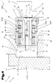
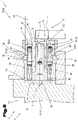
- the tool holding device 48 comprises a support body 49 and a plurality of tool holding modules 50 arranged directly next to one another.
- the number of tool holding modules 50 is given as “n” pieces and is 16 (sixteen) pieces in the present exemplary embodiment.
- the individual tool holding modules 50 are arranged directly next to one another and are also held or attached to the support body 49 .
- each of the coupling bodies 63 can be shifted from a coupling position projecting beyond the longitudinal end face 54, 55 into a release position located within the base body 51 or base bodies 51.
- the return adjustment can only be made possible, but not necessarily brought about by the actuating piston 64 .
- At least one pressure piston 70 can also be provided for each of the tool holding modules 50 .
- the at least one pressure piston 70 is accommodated in a pressure piston chamber 71 arranged in the base body 51 or in the base bodies 51 and is guided in this chamber in the direction of a pressure piston chamber axis 72 . This creates the possibility of pushing at least one of the individual clamping jaws 43, 44, 45, 46 held on the tool changing unit 39 away from one or more of the tool holding modules 50.
- the pressure pistons 70 are each arranged in the base body 51 or in the base bodies 51 such that they can be moved from a pressure position projecting beyond the second transverse end face 57 into a rest position located within the base body 51 or base bodies 51 .
- each of the individual clamping jaws 43, 44, 45, 46 also comprises a coupling section 77 as a component of the coupling device 58, such as this better from FIGS Figures 3 to 5 can be seen.
- Each of the coupling sections 77 comprises a groove-shaped receiving opening 78 which is delimited by a first groove side surface 79 , a second groove side surface 80 and a groove base surface 81 .
- the groove side surfaces 79, 80 each extend in a normal alignment with respect to the forming edge 47 on the side facing away from the forming edge 47 and in a preferably parallel alignment with respect to the clamping surface 30.
- each of the coupling bodies 63 in the coupling position rests against that recess wall which tapers and slopes in the direction away from the respective individual clamping jaw 43, 44, 45, 46, each of the base bodies 51 of the tool holding modules 50 with its second transverse end face 57 will bear against the Groove base 81 pressed.
- the individual clamping jaws 43, 44, 45, 46 With their total number "m”, they have a total thickness in the direction of their forming edge 47. With the choice described above, this is 165 mm, for example.
- the overall thickness of the individual clamping jaws 43, 44, 45, 46 essentially corresponds to an overall length of those arranged next to one another Tool holding modules 50 with their number “n”. If the total thickness of the individual clamping jaws 43, 44, 45, 46 is divided by the number “n”—in the present exemplary embodiment 16 pieces—then the plate-shaped base body 51 has a thickness of 10.3 mm.
- the thickness or thickness is preferably chosen to be 10.5 mm. This means that all individual clamping jaws 43, 44, 45, 46 or just individual ones of them can also be accommodated with the tool changing unit 39 and its tool holding modules 50 and kept coupled thereto.
- the first adjusting means 60 and, if appropriate, the second adjusting means 62 of the same tool holding module 50 is activated and the coupling means or means 59 and optionally 61 are moved into the coupling position and thus brought into coupling engagement with the or the selected individual clamping jaws 43, 44, 45, 46.
- the clamping fixture of the upper clamping jaw 6 is then released. Subsequently, the individual clamping jaw(s) 43, 44, 45, 46 coupled to the tool changing unit 39 can be removed from the upper clamping bar 16, in particular its clamping jaw receptacle 20, and placed in the intended position be spent.
- a total bending length results from the sum of the respective thicknesses or widths.
- the six individual bending dies 95, 96, 97 and 98 form a total bending length of 165 mm when they are in abutting positions.
- Each bending punch 88 in particular the bending punch segments 90 and the individual bending punches 95, 96, 97 and 98 form a forming edge 47 or bending edge at the end facing the workpiece 2, which interacts with the bending die 87 in a known manner.
Landscapes
- Engineering & Computer Science (AREA)
- Mechanical Engineering (AREA)
- Bending Of Plates, Rods, And Pipes (AREA)
- Mounting, Exchange, And Manufacturing Of Dies (AREA)
Applications Claiming Priority (2)
| Application Number | Priority Date | Filing Date | Title |
|---|---|---|---|
| ATA50158/2018A AT520943B1 (de) | 2018-02-21 | 2018-02-21 | Fertigungsanlage mit Werkzeugwechseleinheit und Klemmbacke sowie Verfahren zum Werkzeugwechsel |
| PCT/AT2019/060058 WO2019161425A1 (de) | 2018-02-21 | 2019-02-19 | Fertigungsanlage mit werkzeugwechseleinheit und klemmbacke sowie verfahren zum werkzeugwechsel |
Publications (2)
| Publication Number | Publication Date |
|---|---|
| EP3755480A1 EP3755480A1 (de) | 2020-12-30 |
| EP3755480B1 true EP3755480B1 (de) | 2022-03-30 |
Family
ID=65991474
Family Applications (1)
| Application Number | Title | Priority Date | Filing Date |
|---|---|---|---|
| EP19714302.7A Active EP3755480B1 (de) | 2018-02-21 | 2019-02-19 | Fertigungsanlage mit werkzeugwechseleinheit und klemmbacke sowie verfahren zum werkzeugwechsel |
Country Status (6)
| Country | Link |
|---|---|
| US (1) | US11992872B2 (https=) |
| EP (1) | EP3755480B1 (https=) |
| JP (1) | JP7317843B2 (https=) |
| CN (1) | CN111971132B (https=) |
| AT (1) | AT520943B1 (https=) |
| WO (1) | WO2019161425A1 (https=) |
Families Citing this family (3)
| Publication number | Priority date | Publication date | Assignee | Title |
|---|---|---|---|---|
| EP4180140A1 (de) * | 2021-11-16 | 2023-05-17 | Bystronic Laser AG | Biegemaschine |
| CN116727502A (zh) * | 2023-06-09 | 2023-09-12 | 国动科技有限公司 | 一种机柜加工用折弯设备 |
| CN121551442B (zh) * | 2026-01-19 | 2026-04-07 | 南京蓝昊智能科技有限公司 | 分块式上压刀座 |
Family Cites Families (18)
| Publication number | Priority date | Publication date | Assignee | Title |
|---|---|---|---|---|
| JPS52759A (en) * | 1975-06-24 | 1977-01-06 | Tadashi Amano | Freely stretchable metal mold |
| JPS5962810U (ja) * | 1982-10-18 | 1984-04-25 | 株式人会社アマダ | プレスブレ−キ |
| JPS61103626A (ja) * | 1984-10-29 | 1986-05-22 | Maru Kikai Kogyo Kk | 折曲げ機のクランプ型長さ変換装置 |
| AT385689B (de) | 1986-08-14 | 1988-05-10 | Voest Alpine Ag | Vorrichtung zum abkanten von blechzuschnitten |
| IT1201126B (it) | 1987-01-09 | 1989-01-27 | Salvagnini Transferica Spa | Macchina piegatrice per la produzione di pannelli in lamiera rettangolari a partire da fogli piani di lamiera |
| US5168745A (en) * | 1989-04-10 | 1992-12-08 | Yamazaki Mazak Kabushiki Kaisha | Die exchange apparatus for the use of a press brake |
| JPH0584414U (ja) * | 1992-04-13 | 1993-11-16 | 株式会社アマダ | ベンディング装置における金型自動交換装置 |
| DE19636463C2 (de) | 1996-09-07 | 1998-07-02 | Eht Werkzeugmaschinen Gmbh | Blechbearbeitungsmaschine für plattenförmige Werkstücke mit einem in einzelne Segmente unterteilten Niederhalter |
| IT1284918B1 (it) * | 1996-10-03 | 1998-05-28 | Salvagnini Italia Spa | Macchina pannellatrice dotata di un premilamiera avente lunghezza programmabile |
| DE19733578C2 (de) * | 1997-08-02 | 2002-10-10 | Dreistern Werk Maschinenbau Gmbh & Co Kg | Biegemaschine zum mehrseitigen Biegen eines plattenförmigen Werkstückes |
| IT1309745B1 (it) * | 1999-04-07 | 2002-01-30 | Toolspress S R L | Attrezzatura portautensili ad elementi modulari per presse piegatrici. |
| JP4550246B2 (ja) * | 2000-09-07 | 2010-09-22 | 株式会社吉野機械製作所 | 折曲げ機の上型長さ変換装置 |
| JP4750953B2 (ja) * | 2001-02-14 | 2011-08-17 | 株式会社アマダ | 上型ホルダ装置 |
| FR2844213B1 (fr) | 2002-09-09 | 2004-11-26 | Amada Europ Sa | Systeme de peigne pour intermediaires |
| US6928852B2 (en) * | 2003-03-31 | 2005-08-16 | Wila B.V. | Combination of a press brake clamping system and at least a press brake tool |
| ITPD20110222A1 (it) * | 2011-06-30 | 2012-12-31 | Xp Technology S R L | Macchina utensile pannellatrice con meccanismo migliorato di blocco e sblocco per utensili |
| AT514821B1 (de) * | 2013-10-04 | 2015-06-15 | Trumpf Maschinen Austria Gmbh | Biegepresse und Biegeverfahren |
| AT515781B1 (de) * | 2014-10-08 | 2015-12-15 | Trumpf Maschinen Austria Gmbh | Handhabungssystem für Biegewerkzeuge |
-
2018
- 2018-02-21 AT ATA50158/2018A patent/AT520943B1/de active
-
2019
- 2019-02-19 EP EP19714302.7A patent/EP3755480B1/de active Active
- 2019-02-19 JP JP2020544192A patent/JP7317843B2/ja active Active
- 2019-02-19 US US16/966,783 patent/US11992872B2/en active Active
- 2019-02-19 CN CN201980014055.9A patent/CN111971132B/zh active Active
- 2019-02-19 WO PCT/AT2019/060058 patent/WO2019161425A1/de not_active Ceased
Also Published As
| Publication number | Publication date |
|---|---|
| EP3755480A1 (de) | 2020-12-30 |
| JP7317843B2 (ja) | 2023-07-31 |
| AT520943A4 (de) | 2019-09-15 |
| US11992872B2 (en) | 2024-05-28 |
| AT520943B1 (de) | 2019-09-15 |
| WO2019161425A1 (de) | 2019-08-29 |
| US20210039150A1 (en) | 2021-02-11 |
| CN111971132A (zh) | 2020-11-20 |
| CN111971132B (zh) | 2022-07-19 |
| JP2021514845A (ja) | 2021-06-17 |
Similar Documents
| Publication | Publication Date | Title |
|---|---|---|
| AT511078B1 (de) | Fertigungsanlage mit einem werkzeugwechselsystem | |
| EP2498928B1 (de) | Fertigungsanlage, insbesondere für das freiformbiegen mit einem integrierten werkstück- und werkzeugmanipulator | |
| AT509980B1 (de) | Fertigungsanlage mit werkzeugspeicher | |
| AT519014B1 (de) | Fertigungsanlage mit Manipulationsvorrichtung | |
| EP3755480B1 (de) | Fertigungsanlage mit werkzeugwechseleinheit und klemmbacke sowie verfahren zum werkzeugwechsel | |
| EP2688693B1 (de) | Fertigungsanlage mit hilfsvorrichtung zur zwischenpositionierung von werkstücken | |
| EP2481492B1 (de) | Biegewerkzeug für das Freiformbiegen von Blechen | |
| EP3302840B2 (de) | Fertigungsanlage zur fertigung von werkstücken aus blech sowie verfahren dazu | |
| EP2944390B1 (de) | Biegewerkzeug sowie verfahren zum werkzeugwechsel | |
| EP3551356B1 (de) | Fertigungsanlage mit einem klemmwerkzeug sowie verfahren zur anpassung einer gesamtlänge einer biegekante des klemmwerkzeugs | |
| EP2845663B1 (de) | Biegepresse mit einem Biegewerkzeug aus mehreren Werkzeugelementen | |
| EP3427853B1 (de) | Hinteranschlageinheit sowie damit ausgestattete fertigungsanlage | |
| EP3228396B1 (de) | Biegewerkzeug sowie fertigungsanlage mit einer biegepresse und einem derartigen biegewerkzeug | |
| DE202012001836U1 (de) | Antriebseinrichtung für eine Bearbeitungsmaschine | |
| EP3181254B1 (de) | Fertigungsanlage mit einer werkzeug-manipulationseinheit |
Legal Events
| Date | Code | Title | Description |
|---|---|---|---|
| STAA | Information on the status of an ep patent application or granted ep patent |
Free format text: STATUS: UNKNOWN |
|
| STAA | Information on the status of an ep patent application or granted ep patent |
Free format text: STATUS: THE INTERNATIONAL PUBLICATION HAS BEEN MADE |
|
| PUAI | Public reference made under article 153(3) epc to a published international application that has entered the european phase |
Free format text: ORIGINAL CODE: 0009012 |
|
| STAA | Information on the status of an ep patent application or granted ep patent |
Free format text: STATUS: REQUEST FOR EXAMINATION WAS MADE |
|
| 17P | Request for examination filed |
Effective date: 20200916 |
|
| AK | Designated contracting states |
Kind code of ref document: A1 Designated state(s): AL AT BE BG CH CY CZ DE DK EE ES FI FR GB GR HR HU IE IS IT LI LT LU LV MC MK MT NL NO PL PT RO RS SE SI SK SM TR |
|
| AX | Request for extension of the european patent |
Extension state: BA ME |
|
| DAV | Request for validation of the european patent (deleted) | ||
| DAX | Request for extension of the european patent (deleted) | ||
| GRAP | Despatch of communication of intention to grant a patent |
Free format text: ORIGINAL CODE: EPIDOSNIGR1 |
|
| STAA | Information on the status of an ep patent application or granted ep patent |
Free format text: STATUS: GRANT OF PATENT IS INTENDED |
|
| INTG | Intention to grant announced |
Effective date: 20211029 |
|
| GRAS | Grant fee paid |
Free format text: ORIGINAL CODE: EPIDOSNIGR3 |
|
| GRAA | (expected) grant |
Free format text: ORIGINAL CODE: 0009210 |
|
| STAA | Information on the status of an ep patent application or granted ep patent |
Free format text: STATUS: THE PATENT HAS BEEN GRANTED |
|
| AK | Designated contracting states |
Kind code of ref document: B1 Designated state(s): AL AT BE BG CH CY CZ DE DK EE ES FI FR GB GR HR HU IE IS IT LI LT LU LV MC MK MT NL NO PL PT RO RS SE SI SK SM TR |
|
| REG | Reference to a national code |
Ref country code: GB Ref legal event code: FG4D Free format text: NOT ENGLISH |
|
| REG | Reference to a national code |
Ref country code: CH Ref legal event code: EP |
|
| REG | Reference to a national code |
Ref country code: DE Ref legal event code: R096 Ref document number: 502019003885 Country of ref document: DE |
|
| REG | Reference to a national code |
Ref country code: AT Ref legal event code: REF Ref document number: 1478699 Country of ref document: AT Kind code of ref document: T Effective date: 20220415 |
|
| REG | Reference to a national code |
Ref country code: IE Ref legal event code: FG4D Free format text: LANGUAGE OF EP DOCUMENT: GERMAN |
|
| REG | Reference to a national code |
Ref country code: LT Ref legal event code: MG9D |
|
| PG25 | Lapsed in a contracting state [announced via postgrant information from national office to epo] |
Ref country code: SE Free format text: LAPSE BECAUSE OF FAILURE TO SUBMIT A TRANSLATION OF THE DESCRIPTION OR TO PAY THE FEE WITHIN THE PRESCRIBED TIME-LIMIT Effective date: 20220330 Ref country code: RS Free format text: LAPSE BECAUSE OF FAILURE TO SUBMIT A TRANSLATION OF THE DESCRIPTION OR TO PAY THE FEE WITHIN THE PRESCRIBED TIME-LIMIT Effective date: 20220330 Ref country code: NO Free format text: LAPSE BECAUSE OF FAILURE TO SUBMIT A TRANSLATION OF THE DESCRIPTION OR TO PAY THE FEE WITHIN THE PRESCRIBED TIME-LIMIT Effective date: 20220630 Ref country code: LT Free format text: LAPSE BECAUSE OF FAILURE TO SUBMIT A TRANSLATION OF THE DESCRIPTION OR TO PAY THE FEE WITHIN THE PRESCRIBED TIME-LIMIT Effective date: 20220330 Ref country code: HR Free format text: LAPSE BECAUSE OF FAILURE TO SUBMIT A TRANSLATION OF THE DESCRIPTION OR TO PAY THE FEE WITHIN THE PRESCRIBED TIME-LIMIT Effective date: 20220330 Ref country code: BG Free format text: LAPSE BECAUSE OF FAILURE TO SUBMIT A TRANSLATION OF THE DESCRIPTION OR TO PAY THE FEE WITHIN THE PRESCRIBED TIME-LIMIT Effective date: 20220630 |
|
| REG | Reference to a national code |
Ref country code: NL Ref legal event code: MP Effective date: 20220330 |
|
| PG25 | Lapsed in a contracting state [announced via postgrant information from national office to epo] |
Ref country code: LV Free format text: LAPSE BECAUSE OF FAILURE TO SUBMIT A TRANSLATION OF THE DESCRIPTION OR TO PAY THE FEE WITHIN THE PRESCRIBED TIME-LIMIT Effective date: 20220330 Ref country code: GR Free format text: LAPSE BECAUSE OF FAILURE TO SUBMIT A TRANSLATION OF THE DESCRIPTION OR TO PAY THE FEE WITHIN THE PRESCRIBED TIME-LIMIT Effective date: 20220701 Ref country code: FI Free format text: LAPSE BECAUSE OF FAILURE TO SUBMIT A TRANSLATION OF THE DESCRIPTION OR TO PAY THE FEE WITHIN THE PRESCRIBED TIME-LIMIT Effective date: 20220330 |
|
| PG25 | Lapsed in a contracting state [announced via postgrant information from national office to epo] |
Ref country code: NL Free format text: LAPSE BECAUSE OF FAILURE TO SUBMIT A TRANSLATION OF THE DESCRIPTION OR TO PAY THE FEE WITHIN THE PRESCRIBED TIME-LIMIT Effective date: 20220330 |
|
| PG25 | Lapsed in a contracting state [announced via postgrant information from national office to epo] |
Ref country code: SM Free format text: LAPSE BECAUSE OF FAILURE TO SUBMIT A TRANSLATION OF THE DESCRIPTION OR TO PAY THE FEE WITHIN THE PRESCRIBED TIME-LIMIT Effective date: 20220330 Ref country code: SK Free format text: LAPSE BECAUSE OF FAILURE TO SUBMIT A TRANSLATION OF THE DESCRIPTION OR TO PAY THE FEE WITHIN THE PRESCRIBED TIME-LIMIT Effective date: 20220330 Ref country code: RO Free format text: LAPSE BECAUSE OF FAILURE TO SUBMIT A TRANSLATION OF THE DESCRIPTION OR TO PAY THE FEE WITHIN THE PRESCRIBED TIME-LIMIT Effective date: 20220330 Ref country code: PT Free format text: LAPSE BECAUSE OF FAILURE TO SUBMIT A TRANSLATION OF THE DESCRIPTION OR TO PAY THE FEE WITHIN THE PRESCRIBED TIME-LIMIT Effective date: 20220801 Ref country code: ES Free format text: LAPSE BECAUSE OF FAILURE TO SUBMIT A TRANSLATION OF THE DESCRIPTION OR TO PAY THE FEE WITHIN THE PRESCRIBED TIME-LIMIT Effective date: 20220330 Ref country code: EE Free format text: LAPSE BECAUSE OF FAILURE TO SUBMIT A TRANSLATION OF THE DESCRIPTION OR TO PAY THE FEE WITHIN THE PRESCRIBED TIME-LIMIT Effective date: 20220330 Ref country code: CZ Free format text: LAPSE BECAUSE OF FAILURE TO SUBMIT A TRANSLATION OF THE DESCRIPTION OR TO PAY THE FEE WITHIN THE PRESCRIBED TIME-LIMIT Effective date: 20220330 |
|
| PG25 | Lapsed in a contracting state [announced via postgrant information from national office to epo] |
Ref country code: PL Free format text: LAPSE BECAUSE OF FAILURE TO SUBMIT A TRANSLATION OF THE DESCRIPTION OR TO PAY THE FEE WITHIN THE PRESCRIBED TIME-LIMIT Effective date: 20220330 Ref country code: IS Free format text: LAPSE BECAUSE OF FAILURE TO SUBMIT A TRANSLATION OF THE DESCRIPTION OR TO PAY THE FEE WITHIN THE PRESCRIBED TIME-LIMIT Effective date: 20220730 Ref country code: AL Free format text: LAPSE BECAUSE OF FAILURE TO SUBMIT A TRANSLATION OF THE DESCRIPTION OR TO PAY THE FEE WITHIN THE PRESCRIBED TIME-LIMIT Effective date: 20220330 |
|
| REG | Reference to a national code |
Ref country code: DE Ref legal event code: R097 Ref document number: 502019003885 Country of ref document: DE |
|
| PG25 | Lapsed in a contracting state [announced via postgrant information from national office to epo] |
Ref country code: DK Free format text: LAPSE BECAUSE OF FAILURE TO SUBMIT A TRANSLATION OF THE DESCRIPTION OR TO PAY THE FEE WITHIN THE PRESCRIBED TIME-LIMIT Effective date: 20220330 |
|
| PLBE | No opposition filed within time limit |
Free format text: ORIGINAL CODE: 0009261 |
|
| STAA | Information on the status of an ep patent application or granted ep patent |
Free format text: STATUS: NO OPPOSITION FILED WITHIN TIME LIMIT |
|
| 26N | No opposition filed |
Effective date: 20230103 |
|
| PG25 | Lapsed in a contracting state [announced via postgrant information from national office to epo] |
Ref country code: SI Free format text: LAPSE BECAUSE OF FAILURE TO SUBMIT A TRANSLATION OF THE DESCRIPTION OR TO PAY THE FEE WITHIN THE PRESCRIBED TIME-LIMIT Effective date: 20220330 |
|
| P01 | Opt-out of the competence of the unified patent court (upc) registered |
Effective date: 20230524 |
|
| PG25 | Lapsed in a contracting state [announced via postgrant information from national office to epo] |
Ref country code: MC Free format text: LAPSE BECAUSE OF FAILURE TO SUBMIT A TRANSLATION OF THE DESCRIPTION OR TO PAY THE FEE WITHIN THE PRESCRIBED TIME-LIMIT Effective date: 20220330 |
|
| REG | Reference to a national code |
Ref country code: CH Ref legal event code: PL |
|
| REG | Reference to a national code |
Ref country code: BE Ref legal event code: MM Effective date: 20230228 |
|
| GBPC | Gb: european patent ceased through non-payment of renewal fee |
Effective date: 20230219 |
|
| PG25 | Lapsed in a contracting state [announced via postgrant information from national office to epo] |
Ref country code: LU Free format text: LAPSE BECAUSE OF NON-PAYMENT OF DUE FEES Effective date: 20230219 Ref country code: LI Free format text: LAPSE BECAUSE OF NON-PAYMENT OF DUE FEES Effective date: 20230228 Ref country code: CH Free format text: LAPSE BECAUSE OF NON-PAYMENT OF DUE FEES Effective date: 20230228 |
|
| REG | Reference to a national code |
Ref country code: IE Ref legal event code: MM4A |
|
| PG25 | Lapsed in a contracting state [announced via postgrant information from national office to epo] |
Ref country code: GB Free format text: LAPSE BECAUSE OF NON-PAYMENT OF DUE FEES Effective date: 20230219 |
|
| PG25 | Lapsed in a contracting state [announced via postgrant information from national office to epo] |
Ref country code: IE Free format text: LAPSE BECAUSE OF NON-PAYMENT OF DUE FEES Effective date: 20230219 Ref country code: GB Free format text: LAPSE BECAUSE OF NON-PAYMENT OF DUE FEES Effective date: 20230219 |
|
| PG25 | Lapsed in a contracting state [announced via postgrant information from national office to epo] |
Ref country code: BE Free format text: LAPSE BECAUSE OF NON-PAYMENT OF DUE FEES Effective date: 20230228 |
|
| PGFP | Annual fee paid to national office [announced via postgrant information from national office to epo] |
Ref country code: FR Payment date: 20250226 Year of fee payment: 7 |
|
| PG25 | Lapsed in a contracting state [announced via postgrant information from national office to epo] |
Ref country code: CY Free format text: LAPSE BECAUSE OF FAILURE TO SUBMIT A TRANSLATION OF THE DESCRIPTION OR TO PAY THE FEE WITHIN THE PRESCRIBED TIME-LIMIT; INVALID AB INITIO Effective date: 20190219 |
|
| PG25 | Lapsed in a contracting state [announced via postgrant information from national office to epo] |
Ref country code: HU Free format text: LAPSE BECAUSE OF FAILURE TO SUBMIT A TRANSLATION OF THE DESCRIPTION OR TO PAY THE FEE WITHIN THE PRESCRIBED TIME-LIMIT; INVALID AB INITIO Effective date: 20190219 |
|
| PG25 | Lapsed in a contracting state [announced via postgrant information from national office to epo] |
Ref country code: TR Free format text: LAPSE BECAUSE OF FAILURE TO SUBMIT A TRANSLATION OF THE DESCRIPTION OR TO PAY THE FEE WITHIN THE PRESCRIBED TIME-LIMIT Effective date: 20220330 |
|
| PGFP | Annual fee paid to national office [announced via postgrant information from national office to epo] |
Ref country code: DE Payment date: 20260218 Year of fee payment: 8 |
|
| PGFP | Annual fee paid to national office [announced via postgrant information from national office to epo] |
Ref country code: AT Payment date: 20260219 Year of fee payment: 8 |
|
| PGFP | Annual fee paid to national office [announced via postgrant information from national office to epo] |
Ref country code: IT Payment date: 20260219 Year of fee payment: 8 |