EP3753798A1 - Haltevorrichtung für einen innenraum eines fahrzeugs - Google Patents
Haltevorrichtung für einen innenraum eines fahrzeugs Download PDFInfo
- Publication number
- EP3753798A1 EP3753798A1 EP20180360.8A EP20180360A EP3753798A1 EP 3753798 A1 EP3753798 A1 EP 3753798A1 EP 20180360 A EP20180360 A EP 20180360A EP 3753798 A1 EP3753798 A1 EP 3753798A1
- Authority
- EP
- European Patent Office
- Prior art keywords
- holding device
- recess
- interior
- holding
- device body
- Prior art date
- Legal status (The legal status is an assumption and is not a legal conclusion. Google has not performed a legal analysis and makes no representation as to the accuracy of the status listed.)
- Granted
Links
Images


Classifications
-
- B—PERFORMING OPERATIONS; TRANSPORTING
- B60—VEHICLES IN GENERAL
- B60R—VEHICLES, VEHICLE FITTINGS, OR VEHICLE PARTS, NOT OTHERWISE PROVIDED FOR
- B60R11/00—Arrangements for holding or mounting articles, not otherwise provided for
-
- B—PERFORMING OPERATIONS; TRANSPORTING
- B60—VEHICLES IN GENERAL
- B60B—VEHICLE WHEELS; CASTORS; AXLES FOR WHEELS OR CASTORS; INCREASING WHEEL ADHESION
- B60B30/00—Means for holding wheels or parts thereof
- B60B30/06—Means for holding wheels or parts thereof engaging the wheel body, e.g. the rim
- B60B30/08—Means for holding wheels or parts thereof engaging the wheel body, e.g. the rim the central part of the wheel body
-
- B—PERFORMING OPERATIONS; TRANSPORTING
- B60—VEHICLES IN GENERAL
- B60N—SEATS SPECIALLY ADAPTED FOR VEHICLES; VEHICLE PASSENGER ACCOMMODATION NOT OTHERWISE PROVIDED FOR
- B60N2/00—Seats specially adapted for vehicles; Arrangement or mounting of seats in vehicles
- B60N2/24—Seats specially adapted for vehicles; Arrangement or mounting of seats in vehicles for particular purposes or particular vehicles
- B60N2/242—Bus seats
-
- B—PERFORMING OPERATIONS; TRANSPORTING
- B61—RAILWAYS
- B61D—BODY DETAILS OR KINDS OF RAILWAY VEHICLES
- B61D33/00—Seats
- B61D33/0007—Details; Accessories
-
- B—PERFORMING OPERATIONS; TRANSPORTING
- B61—RAILWAYS
- B61D—BODY DETAILS OR KINDS OF RAILWAY VEHICLES
- B61D37/00—Other furniture or furnishings
-
- B—PERFORMING OPERATIONS; TRANSPORTING
- B61—RAILWAYS
- B61D—BODY DETAILS OR KINDS OF RAILWAY VEHICLES
- B61D45/00—Means or devices for securing or supporting the cargo, including protection against shocks
- B61D45/001—Devices for fixing to walls or floors
-
- B—PERFORMING OPERATIONS; TRANSPORTING
- B62—LAND VEHICLES FOR TRAVELLING OTHERWISE THAN ON RAILS
- B62H—CYCLE STANDS; SUPPORTS OR HOLDERS FOR PARKING OR STORING CYCLES; APPLIANCES PREVENTING OR INDICATING UNAUTHORIZED USE OR THEFT OF CYCLES; LOCKS INTEGRAL WITH CYCLES; DEVICES FOR LEARNING TO RIDE CYCLES
- B62H3/00—Separate supports or holders for parking or storing cycles
- B62H3/02—Separate supports or holders for parking or storing cycles involving means for gripping the cycle by the handlebars or by the upper part of the frame
-
- B—PERFORMING OPERATIONS; TRANSPORTING
- B62—LAND VEHICLES FOR TRAVELLING OTHERWISE THAN ON RAILS
- B62H—CYCLE STANDS; SUPPORTS OR HOLDERS FOR PARKING OR STORING CYCLES; APPLIANCES PREVENTING OR INDICATING UNAUTHORIZED USE OR THEFT OF CYCLES; LOCKS INTEGRAL WITH CYCLES; DEVICES FOR LEARNING TO RIDE CYCLES
- B62H3/00—Separate supports or holders for parking or storing cycles
- B62H3/04—Separate supports or holders for parking or storing cycles involving forked supports of brackets for holding a wheel
-
- B—PERFORMING OPERATIONS; TRANSPORTING
- B60—VEHICLES IN GENERAL
- B60N—SEATS SPECIALLY ADAPTED FOR VEHICLES; VEHICLE PASSENGER ACCOMMODATION NOT OTHERWISE PROVIDED FOR
- B60N2/00—Seats specially adapted for vehicles; Arrangement or mounting of seats in vehicles
- B60N2/90—Details or parts not otherwise provided for
- B60N2002/905—Details or parts not otherwise provided for the head-rest or seat used as an anchorage point, for an object not covered by groups in B60N, e.g. for a canvas
-
- B—PERFORMING OPERATIONS; TRANSPORTING
- B62—LAND VEHICLES FOR TRAVELLING OTHERWISE THAN ON RAILS
- B62H—CYCLE STANDS; SUPPORTS OR HOLDERS FOR PARKING OR STORING CYCLES; APPLIANCES PREVENTING OR INDICATING UNAUTHORIZED USE OR THEFT OF CYCLES; LOCKS INTEGRAL WITH CYCLES; DEVICES FOR LEARNING TO RIDE CYCLES
- B62H2700/00—Supports or stands for two-wheel vehicles
-
- B—PERFORMING OPERATIONS; TRANSPORTING
- B62—LAND VEHICLES FOR TRAVELLING OTHERWISE THAN ON RAILS
- B62K—CYCLES; CYCLE FRAMES; CYCLE STEERING DEVICES; RIDER-OPERATED TERMINAL CONTROLS SPECIALLY ADAPTED FOR CYCLES; CYCLE AXLE SUSPENSIONS; CYCLE SIDECARS, FORECARS, OR THE LIKE
- B62K3/00—Bicycles
- B62K3/002—Bicycles without a seat, i.e. the rider operating the vehicle in a standing position, e.g. non-motorized scooters; non-motorized scooters with skis or runners
Definitions
- the invention relates to a holding device for an interior of a vehicle, in particular a rail vehicle or a bus.
- Vehicle interiors especially interiors of means of transport such as subways, suburban trains, trams, regional and long-distance trains or buses, etc. must have fastening devices to secure, for example, prams, bicycles and wheelchairs etc. against unintentional movement.
- fastening loops which can be connected, for example, to holding rods, or roller belt devices, which can be provided, for example, on seat rods, are known.
- the safety device comprises a carrier element, which is connected to a car body structure, as well as a securing element articulated to the carrier element.
- the securing element can, for example, be designed as a securing bracket.
- a retaining element is also provided as a stop for the securing element.
- this approach has the disadvantage of a complex arrangement consisting of several components, which is particularly suitable for a dedicated wheelchair parking space in the vehicle.
- the invention is based on the object of specifying a structurally simple holding device which has been further developed compared to the prior art and which can be used universally with regard to its arrangement in the vehicle.
- this object is achieved with a holding device of the type mentioned at the outset, in which a device body is provided which has at least one recess which is partially delimited by the device body and into which a contact body can be inserted, which can be positively connected to the device body.
- a device body is provided which has at least one recess which is partially delimited by the device body and into which a contact body can be inserted, which can be positively connected to the device body.
- the device body is formed in one piece with an interior part of the vehicle or if the device body can be connected to an interior part of the vehicle.
- the interior furnishing part is, for example, a seat or a seating group, a backrest, etc.
- This measure achieves great flexibility with regard to possible uses of the holding device according to the invention. If the holding device is, for example, formed in one piece with a seat or connected to the seat, a passenger can leave rolling devices etc. in his vicinity while he is sitting and does not have to go to separate zones in order to park the rolling devices etc. there. Furthermore, if the rolling devices etc. are stored under the seat, it is avoided that the rolling devices etc.
- the device body is formed in one piece with an interior part of the vehicle, then a particularly compact holding device achieved which, for example, does not hinder cleaning work in the interior. If the device body can be connected to an interior part of the vehicle, this facilitates retrofitting with holding devices according to the invention.
- the device body is at least partially lined with an adhesive body in the region of the at least one recess.
- the adhesive body is designed as a rubber element or rubber lip, etc., for example. This measure increases the frictional connection or the frictional connection between the device body and the contact body in the recess.
- a favorable solution is achieved if the adhesive body is at least partially magnetic. In the case of metallic contact bodies, this measure brings about a particularly secure hold of the contact body in the recess. When a frictional connection or frictional connection between the device body and the contact body is already in effect, redundant securing of the contact body in the recess is achieved.
- the device body has a non-slip coating in the region of the at least one recess. This measure also promotes the frictional connection or the frictional connection between the device body and the contact body in the recess.
- the device body has a locking device in the region of the at least one recess.
- the locking device has, for example, a first locking means, which via a first spring with the Device body is connected, or at least one locking knob. A simple and at the same time secure locking of the rolling device etc. is thereby effected. Because the first locking means or the locking knob is provided in the area of the recess, the locking device is designed to be particularly space-saving and compact.
- Fig. 1 shows a schematic representation of a seat 1 as an interior part in an interior of a rail vehicle.
- the seat 1 is shown as a floor plan, has a seat surface 2 and a backrest 3 and functions in the area of the seat surface 2 as a device body 4 of a first exemplary embodiment of a holding device according to the invention.
- the device body 4 is thus formed in one piece with the seat 1.
- the device body 4 has a wedge-shaped recess 5 which is provided in the seat surface 2 of the seat 1 and is lined with an adhesive body 6.
- the recess 5 is designed, for example, cylindrical or partially cylindrical, etc.
- the recess 5 is partially delimited by the device body 4 and is open to a front side 7 of the seat surface 2 of the seat 1.
- the adhesive body 6 is designed as a rubber lip and glued to the seat 1, which is made of a hard and resistant plastic. A magnet is incorporated into the rubber lip, ie the adhesive body 6 is partially magnetic. This is a cheap solution.
- the entire adhesive body 6 is made magnetic, that the device body 4 is made magnetic in the area of the recess 5 or that a separate magnet separated from the rubber lip is arranged in the area of the recess 5.
- a metallic handlebar 8 as a roller 9, which in Fig. 3 is shown, introduced rolling device running.
- the handlebar 8 thus functions as a contact body with respect to the adhesive body 6. Due to a frictional connection between the adhesive body 6 and the handlebar 8, ie the contact body, the handlebar 8 of the scooter 9 is fixed in the device body 4 of the holding device.
- the magnet worked into the rubber lip is provided in the contact area between the adhesive body 6 and the handlebar 8, ie the contact body.
- the otherwise cylindrical handlebar 8 is spherical-convex in the contact area with the adhesive body 6 and the adhesive body 6 is spherical-concave, causing the handlebar 8 to engage and lock in the adhesive body 6.
- the frictional connection is reinforced due to a magnetic force between the adhesive body 6 and the handlebar 8. A certain amount of force is required to release the handlebar 8 from the holding device.
- the seat 2 is in that in Fig. 1
- the embodiment variant shown of a holding device according to the invention is not designed to be foldable. According to the invention, however, it is also possible that the seat 1 is designed as a folding seat.
- a seat 1 is also shown schematically and as a floor plan as an interior part of an interior of a rail vehicle, which has a seat surface 2 and a backrest 3.
- a rear part of the backrest 3 inclined by approximately 45 ° as a device body 4 of a second exemplary embodiment variant of a holding device according to the invention.
- the holding device is provided in the area of an upper side of the rear part of the backrest 3, the device body 4 is formed in one piece with the rear part of the backrest 3.
- the device body 4 has a partially cylindrical, partially rectangular recess 5 which is lined with an adhesive body 6 designed as a rubber lip. According to the invention it is also conceivable to make the recess e.g. partially wedge-shaped and partially cylindrical.
- the adhesive body 6 is glued to the rear part of the backrest 3, but it is also conceivable to clamp it to the rear part of the backrest 3, for example.
- the recess 5 is arranged in the area of a rear side 10 of the rear part of the backrest 3, ie in the area of this rear side 10 a contact body (a Fig. 1 handlebar 8 shown in FIG Fig. 3
- the roller 9 shown, ie a roller device) can be introduced into the recess 5 and connected to the device body 4 in a non-positive or frictional manner via the adhesive body 6.
- a locking device 11 which has a first locking means 12 and a second locking means 13.
- the first locking means 12 and the second locking means 13 are designed as locking pins, aligned parallel to the rear 10 and protrude into the recess 5.
- the first locking means 12 is via a first spring 14 and the second locking means 13 via a second spring 15 with the rear part the backrest 3, ie connected to the device body 4 and thus resiliently mounted.
- the first locking means 12 and the first spring 14 are arranged and guided in a first guide sleeve 16 of the device body 4, the second locking means 13 and the second spring 15 are arranged and guided in a second guide sleeve 17 of the device body 4.
- the first spring 14 and the second spring 15 are also aligned parallel to the rear side 10.
- the first locking means 12 and the second locking means 13 In order to insert the contact body into the recess 5 or to remove it again from the recess 5, the first locking means 12 and the second locking means 13 must be pushed out of the recess 5 against spring forces of the first spring 14 and the second spring 15. If the first locking means 12 and the second locking means 13 are released from a pretensioned state of the first spring 14 and the second spring 15, the first locking means 12 and the second locking means 13 move laterally into the recess 5 due to the spring forces and lock the contact body .
- first locking means 12 and the second locking means 13 as locking pins is a favorable solution. According to the invention, however, it is also conceivable to provide locking pawls or locking hooks (similar to a lobster clasp) as first locking means 12 and second locking means 13 and to connect these to the device body 4 via swivel joints and torsion springs. The contact body can be locked in the recess 5 and released again by turning these locking pawls or locking hooks.
- first locking means 12 and the second locking means 13 have handles for easier operation and that the first locking means 12 and the second locking means 13 are themselves locked in the device body 4 after a certain deflection (e.g. via notches the first locking means 12, the second locking means 13, in the first guide sleeve 16 and in the second guide sleeve 17) in order to facilitate insertion of the contact body into the recess 5.
- a certain deflection e.g. via notches the first locking means 12, the second locking means 13, in the first guide sleeve 16 and in the second guide sleeve 17
- the locking device 11 has only the first locking means 12, the first spring 14 and the first guide sleeve 16, ie that only the first locking means 12 locks the recess 5 and the second locking means 13, the second spring 15 and the second guide sleeve 17 is dispensed with.
- a free-standing standing seat back in the interior of the rail vehicle functions as a device body 4 of the holding device, ie the device body 4 is formed in one piece with the standing seat back, or the device body 4 is connected to the standing seat back.
- the standing backrest is also an interior part of the rail vehicle.
- Fig. 3 shows an interior of a rail vehicle in a schematic representation and as an elevation.
- the interior has a seating group 18 which is connected to an inner wall 19 of the rail vehicle.
- a storage space 20 is provided in the lower area of the seating group 18.
- the seating group 18 has a third exemplary embodiment variant of a holding device according to the invention in the area of a seat surface 2 of a seat 1.
- the holding device comprises a device body 4 which is formed in one piece with the seat 1.
- a recess 5 is provided, which with an in Fig. 1 adhesive body 6 shown is lined.
- a steering rod 8 of a rolling device designed as a roller 9 (the steering rod 8 is thus part of the rolling device) is connected to the device body 4 in a non-positive or frictional manner via the adhesive body 6 as a contact body.
- the scooter 9 is thereby fixed in the holding device and parked in the area of the storage space 20 in the lower area of the seating group 18.
- the storage space 20 has a load securing device which comprises a load securing rail.
- the load securing rail is incorporated into a floor of the rail vehicle and lined with a metallic U-profile. Are in the load securing rail Rolls of the scooter 9 introduced, whereby its parking space and its orientation parallel to the inner wall 19 is defined.
- a slight frictional connection is provided between the rollers and the load securing rail, whereby unintentional movements of the scooter 9 are avoided.
- it is conceivable to provide a plurality of load securing rails for example one load securing rail for each pair of seats in seating group 18 facing away from one another.
- the load securing rail is not aligned parallel, but rather obliquely, to the inner wall 19.
- scooters 9 or electric scooters can be fixed with the holding device.
- Elongated, rod-shaped or bar-shaped bodies are particularly suitable for fixing in the holding device.
- the holding device according to the invention is provided in the interior of the rail vehicle.
- it can be used in the interiors of different vehicles, e.g. also in buses such as buses, trolleybuses, electric buses etc.
- the seating group 18 can also have more than one recess 5, which are advantageously arranged offset from one another in order to be able to stow a number of scooters 9 fixed in holding devices according to the invention in a smooth manner.
- a support rod 21 of an interior of a rail vehicle is shown schematically, in section and as a floor plan.
- a device body 4 of a fourth exemplary embodiment variant of a holding device according to the invention is welded to the holding rod 21, that is to say connected in a materially bonded manner.
- the device body 4 has a with an adhesive body 6 lined recess 5, in which a handlebar 8 of an in Fig. 3 shown roller 9, ie a rolling device is introduced.
- the contact body is connected to the device body 4 in a non-positive or frictional manner via the adhesive body 6.
- the recess 5 and the adhesive body 6 correspond structurally and functionally to that embodiment variant of a holding device according to the invention which is shown in FIG Fig. 1 is shown.
- Fig. 5 shows an inner wall 19 of a rail vehicle schematically, in section and as a floor plan.
- a device body 4 of a fifth exemplary embodiment variant of a holding device according to the invention is connected to the inner wall 19, projecting into an interior space of the rail vehicle, via a first screw 22, a second screw 23 and further screws.
- the device body 4 has a recess 5 lined with an adhesive body 6, into which a handlebar 8 of an in Fig. 3 shown roller 9, ie a rolling device is introduced.
- the adhesive body 6 designed as a rubber bead is glued to the device body 4 in the region of the recess 5.
- the contact body is connected to the device body 4 in a non-positive or frictional manner via the adhesive body 6.
- the locking device 11 in Fig. 5 The holding device shown has a locking knob 24, which is designed as a thickening of the adhesive body 6, that is to say is made in one piece with the adhesive body 6.
- a resistance due to the locking knob 24 must be overcome, ie the locking knob 24 must be deformed or pressed in by the contact body by applying force.
- the contact body After the contact body has been inserted into the recess 5 and the resistance due to the locking knob 24 has been overcome, the contact body is locked in the holding device. According to the invention, more than one locking knob 24 can of course also be provided.
Landscapes
- Engineering & Computer Science (AREA)
- Mechanical Engineering (AREA)
- Transportation (AREA)
- Aviation & Aerospace Engineering (AREA)
- Seats For Vehicles (AREA)
- Passenger Equipment (AREA)
- Vehicle Step Arrangements And Article Storage (AREA)
Abstract
Um günstige Konstruktionsbedingungen zu schaffen, wird vorgeschlagen, dass ein Vorrichtungskörper (4) vorgesehen ist, welcher zumindest eine Ausnehmung (5) aufweist, welche von dem Vorrichtungskörper (4) teilweise umgrenzt ist und in welche ein Kontaktkörper einführbar ist, welcher mit dem Vorrichtungskörper (4) kraftschlüssig verbindbar ist.
Description
- Die Erfindung betrifft eine Haltevorrichtung für einen Innenraum eines Fahrzeugs, insbesondere eines Schienenfahrzeugs oder eines Busses.
- Fahrzeuginnenräume, insbesondere Innenräume von Verkehrsmitteln wie U-, S-Bahnen, Straßenbahnen, Regional- und Fernverkehrszügen oder Bussen etc. müssen Befestigungsvorrichtungen aufweisen, um beispielsweise Kinderwagen, Fahrräder und Rollstühle etc. gegen unbeabsichtigte Bewegungen zu sichern.
Aus dem Stand der Technik sind beispielsweise Befestigungsschlaufen, welche z.B. mit Haltestangen verbunden sein können, oder Rollgurtvorrichtungen, welche z.B. an Sitzgestängen vorgesehen sein können, bekannt. - Aus dem Stand der Technik ist beispielsweise die
DE 10 2009 004 525 A1 bekannt. Darin ist eine Rollstuhl-Fangvorrichtung für ein Fahrzeug beschrieben. Die Fangvorrichtung umfasst ein Trägerelement, welches mit einem Wagenkastenaufbau verbunden ist, sowie ein mit dem Trägerelement gelenkig gekoppeltes Sicherungselement. Das Sicherungselement kann beispielsweise als Sicherungsbügel ausgebildet sein. Als Anschlag für das Sicherungselement ist zusätzlich ein Halteelement vorgesehen. - Dieser Ansatz weist in seiner bekannten Form den Nachteil einer komplexen, aus mehreren Bauteilen bestehenden Anordnung auf, welche insbesondere für einen dedizierten Rollstuhlabstellplatz in dem Fahrzeug geeignet ist.
- Der Erfindung liegt die Aufgabe zugrunde, eine gegenüber dem Stand der Technik weiterentwickelte, konstruktiv einfache Haltevorrichtung anzugeben, welche im Hinblick auf deren Anordnung im Fahrzeug universell einsetzbar ist.
- Erfindungsgemäß wird diese Aufgabe gelöst mit einer Haltevorrichtung der eingangs genannten Art, bei der ein Vorrichtungskörper vorgesehen ist, welcher zumindest eine Ausnehmung aufweist, welche von dem Vorrichtungskörper teilweise umgrenzt ist und in welche ein Kontaktkörper einführbar ist, welcher mit dem Vorrichtungskörper kraftschlüssig verbindbar ist.
Dadurch wird eine rasche und mit wenigen Handgriffen bzw. nur mit einem Handgriff durchführbare Fixierung des Kontaktkörpers erzielt. Der Kontaktkörper ist beispielsweise Teil einer Rollvorrichtung (insbesondere eines Rollers). Durch Einführen des Kontaktkörpers in die Ausnehmung wird ein Kraftschluss bzw. ein Reibschluss bewirkt und der Kontaktkörper ist dadurch in der Ausnehmung gehalten. - Eine vorsteilhafte Ausgestaltung erhält man, wenn der Vorrichtungskörper einstückig mit einem Inneneinrichtungsteil des Fahrzeugs ausgebildet ist oder wenn der Vorrichtungskörper mit einem Inneneinrichtungsteil des Fahrzeugs verbindbar ist.
Das Inneneinrichtungsteil ist beispielsweise ein Sitz oder eine Sitzgruppe, eine Lehne etc.
Durch diese Maßnahme wird eine große Flexibilität im Hinblick auf Einsatzmöglichkeiten der erfindungsgemäßen Haltevorrichtung erzielt.
Ist die Haltevorrichtung beispielsweise einstückig mit einem Sitz ausgebildet oder mit dem Sitz verbunden, so kann ein Fahrgast Rollvorrichtungen etc. in seiner Nähe belassen während er sitzt und muss sich nicht separate Zonen begeben, um die Rollvorrichtungen etc. dort abzustellen.
Weiterhin wird beispielsweise bei einer Lagerung der Rollvorrichtungen etc. unter dem Sitz vermieden, dass die Rollvorrichtungen etc. in Stehplatz-, Kinderwagen- oder Rollstuhlbereichen abgestellt sind und Hindernisse bzw. Stolperfallen für sich dort aufhaltende Fahrgäste darstellen. Ist der Vorrichtungskörper einstückig mit einem Inneneinrichtungsteil des Fahrzeugs ausgebildet, so wird eine besonders kompakte Haltevorrichtung erzielt, welche beispielsweise Reinigungsarbeiten in dem Innenraum nicht behindert.
Ist der Vorrichtungskörper mit einem Inneneinrichtungsteil des Fahrzeugs verbindbar, so werden dadurch Nachrüstungen mit erfindungsgemäßen Haltevorrichtungen begünstigt. - Es ist günstig, wenn der Vorrichtungskörper im Bereich der zumindest einen Ausnehmung zumindest teilweise mit einem Haftkörper ausgekleidet ist.
Der Haftkörper ist beispielsweise als Gummielement oder Gummilippe etc. ausgeführt.
Durch diese Maßnahme wird der Kraftschluss bzw. der Reibschluss zwischen dem Vorrichtungskörper und dem Kontaktkörper in der Ausnehmung gesteigert. - Eine günstige Lösung wird erreicht, wenn der Haftkörper zumindest teilweise magnetisch ausgeführt ist.
Durch diese Maßnahme wird, bei metallischen Kontaktkörpern, ein besonders sicherer Halt des Kontaktkörpers in der Ausnehmung bewirkt. Bei bereits wirkendem Kraftschluss bzw. Reibschluss zwischen dem Vorrichtungskörper und dem Kontaktkörper wird dadurch eine redundante Sicherung des Kontaktkörpers in der Ausnehmung erzielt. - Ferner ist es hilfreich, wenn der Vorrichtungskörper im Bereich der zumindest einen Ausnehmung eine rutschhemmende Beschichtung aufweist.
Auch diese Maßnahme fördert den Kraftschluss bzw. den Reibschluss zwischen dem Vorrichtungskörper und dem Kontaktkörper in der Ausnehmung. - Eine günstige Lösung wird erreicht, wenn der Vorrichtungskörper im Bereich der zumindest einen Ausnehmung eine Verriegelungsvorrichtung aufweist.
Die Verriegelungsvorrichtung weist beispielsweise ein erstes Arretiermittel, welches über eine erste Feder mit dem Vorrichtungskörper verbunden ist, oder zumindest eine Arretiernoppe auf.
Dadurch wird eine einfache und zugleich sichere Verriegelung der Rollvorrichtung etc. bewirkt.
Dadurch, dass das erste Arretiermittel oder die Arretiernoppe im Bereich der Ausnehmung vorgesehen ist, ist die Verriegelungsvorrichtung besonders platzsparend und kompakt ausgeführt. - Eine vorteilhafte Ausgestaltung erhält man, wenn die zumindest eine Ausnehmung zumindest teilweise keilförmig ausgebildet ist.
Durch diese Maßnahme wird ein Einführen des Kontaktkörpers in die erfindungsgemäße Haltevorrichtung erleichtert. - Nachfolgend wird die Erfindung anhand von Ausführungsbeispielen näher erläutert.
- Es zeigen beispielhaft:
- Fig. 1:
- Einen Sitz eines Fahrzeuginnenraums, welcher als Vorrichtungskörper einer ersten beispielhaften Ausführungsvariante einer erfindungsgemäßen Haltevorrichtung fungiert,
- Fig. 2:
- Einen weiteren Sitz eines Fahrzeuginnenraums, bei welchem ein Hinterteil einer Lehne als Vorrichtungskörper einer zweiten beispielhaften Ausführungsvariante einer erfindungsgemäßen Haltevorrichtung fungiert,
- Fig. 3:
- Einen Ausschnitt aus einem Fahrzeuginnenraum mit einer Sitzgruppe, welche als Vorrichtungskörper einer dritten beispielhaften Ausführungsvariante einer erfindungsgemäßen Haltevorrichtung, mittels welcher ein Roller fixiert ist, ausgeführt ist,
- Fig. 4:
- Eine Haltestange eines Fahrzeuginnenraums in geschnittener Darstellung, mit welcher eine vierte beispielhafte Ausführungsvariante einer erfindungsgemäßen Haltevorrichtung verbunden ist, und
- Fig. 5:
- Eine Innenwand eines Fahrzeugs in geschnittener Darstellung, mit welcher eine fünfte beispielhafte Ausführungsvariante einer erfindungsgemäßen Haltevorrichtung verbunden ist.
-
Fig. 1 zeigt eine schematische Darstellung eines Sitzes 1 als Inneneinrichtungsteil in einem Innenraum eines Schienenfahrzeugs. Der Sitz 1 ist als Grundriss dargestellt, weist eine Sitzfläche 2 sowie eine Lehne 3 auf und fungiert im Bereich der Sitzfläche 2 als Vorrichtungskörper 4 einer ersten beispielhaften Ausführungsvariante einer erfindungsgemäßen Haltevorrichtung. Der Vorrichtungskörper 4 ist also einstückig mit dem Sitz 1 ausgebildet.
Der Vorrichtungskörper 4 weist eine keilförmige Ausnehmung 5 auf, welche in der Sitzfläche 2 des Sitzes 1 vorgesehen und mit einem Haftkörper 6 ausgekleidet ist.
Erfindungsgemäß ist es auch denkbar, dass die Ausnehmung 5 z.B. zylindrisch oder teilweise zylindrisch etc. ausgeführt ist.
Die Ausnehmung 5 ist teilweise von dem Vorrichtungskörper 4 umgrenzt und zu einer Vorderseite 7 der Sitzfläche 2 des Sitzes 1 hin offen.
Der Haftkörper 6 ist als Gummilippe ausgebildet und mit dem Sitz 1, welcher in einem harten und widerstandsfähigen Kunststoff ausgebildet ist, verklebt. In die Gummilippe ist ein Magnet eingearbeitet, d.h. der Haftkörper 6 ist teilweise magnetisch ausgeführt.
Dabei handelt es sich um eine günstige Lösung. Erfindungsgemäß ist es auch denkbar, den Vorrichtungskörper 4 im Bereich der Ausnehmung 5 mit einem rutschhemmenden Belag zu beschichten.
Weiterhin ist es denkbar, die Ausnehmung 5 nicht zur Gänze, sondern nur teilweise mit dem Haftkörper 6 auszukleiden bzw. zu beschichten, d.h. beispielsweise nur in jenem Bereich der Ausnehmung 5, in welcher ein Kontaktkörper fixiert werden soll.
Ferner ist es vorstellbar, dass der ganze Haftkörper 6 magnetisch ausgeführt ist, dass der Vorrichtungskörper 4 im Bereich der Ausnehmung 5 magnetisch ausgeführt ist oder dass im Bereich der Ausnehmung 5 ein separater, von der Gummilippe getrennter Magnet angeordnet ist. - In die Ausnehmung 5 ist eine metallische Lenkstange 8 einer als Roller 9, welcher in
Fig. 3 gezeigt ist, ausgeführten Rollvorrichtung eingeführt. Die Lenkstange 8 fungiert demnach als Kontaktkörper in Bezug auf den Haftkörper 6. Aufgrund eines Kraftschlusses bzw. Reibschlusses zwischen dem Haftkörper 6 und der Lenkstange 8, d.h. dem Kontaktkörper, ist die Lenkstange 8 des Rollers 9 in dem Vorrichtungskörper 4 der Haltevorrichtung fixiert.
Der in die Gummilippe eingearbeitete Magnet ist im Kontaktbereich zwischen dem Haftkörper 6 und der Lenkstange 8, d.h. dem Kontaktkörper, vorgesehen. Weiterhin ist die ansonsten zylindrische Lenkstange 8 im Kontaktbereich mit dem Haftkörper 6 kugelförmig-konvex ausgebildet und der Haftkörper 6 kugelförmig-konkav, wodurch ein Einrasten und eine Arretierung der Lenkstange 8 in den bzw. in dem Haftkörper 6 bewirkt werden.
Der Kraftschluss wird aufgrund einer magnetischen Kraft zwischen dem Haftkörper 6 und der Lenkstange 8 verstärkt.
Es ist ein gewisser Kraftaufwand erforderlich, um die Lenkstange 8 wieder aus der Haltevorrichtung zu lösen. - Die Sitzfläche 2 ist in jener in
Fig. 1 gezeigten Ausführungsvariante einer erfindungsgemäßen Haltevorrichtung nicht klappbar ausgeführt. Erfindungsgemäß ist es jedoch auch möglich, dass der Sitz 1 als Klappsitz ausgebildet ist. - In
Fig. 2 ist ebenfalls ein Sitz 1 als Inneneinrichtungsteil eines Innenraums eines Schienenfahrzeugs schematisch und als Grundriss dargestellt, welcher eine Sitzfläche 2 und eine Lehne 3 aufweist.
Im Unterschied zuFig. 1 fungiert inFig. 2 ein um ca. 45° geneigtes Hinterteil der Lehne 3 als Vorrichtungskörper 4 einer zweiten beispielhaften Ausführungsvariante einer erfindungsgemäßen Haltevorrichtung. Die Haltevorrichtung ist im Bereich einer Oberseite des Hinterteils der Lehne 3 vorgesehen, der Vorrichtungskörper 4 ist einstückig mit dem Hinterteil der Lehne 3 ausgebildet. - Der Vorrichtungskörper 4 weist eine teilweise zylindrische, teilweise rechteckförmige Ausnehmung 5 auf, welche mit einem als Gummilippe ausgeführten Haftkörper 6 ausgekleidet ist. Erfindungsgemäß ist es auch vorstellbar, die Ausnehmung z.B. teilweise keilförmig und teilweise zylindrisch auszubilden. Der Haftkörper 6 ist mit dem Hinterteil der Lehne 3 verklebt, es ist jedoch auch denkbar, diesen beispielsweise mit dem Hinterteil der Lehne 3 zu verklemmen.
- Die Ausnehmung 5 ist im Bereich einer Rückseite 10 des Hinterteils der Lehne 3 angeordnet, d.h. im Bereich dieser Rückseite 10 kann ein Kontaktkörper (eine in
Fig. 1 gezeigte Lenkstange 8 eines inFig. 3 dargestellten Rollers 9, d.h. einer Rollvorrichtung) in die Ausnehmung 5 eingeführt werden und kraftschlüssig bzw. reibschlüssig über den Haftkörper 6 mit dem Vorrichtungskörper 4 verbunden werden. - Im Bereich der Ausnehmung 5 ist eine Verriegelungsvorrichtung 11 vorgesehen, welche ein erstes Arretiermittel 12 und ein zweites Arretiermittel 13 aufweist. Das erste Arretiermittel 12 und das zweite Arretiermittel 13 sind als Arretierstifte ausgebildet, parallel zu der Rückseite 10 ausgerichtet und ragen in die Ausnehmung 5. Das erste Arretiermittel 12 ist über eine erste Feder 14 und das zweite Arretiermittel 13 über eine zweite Feder 15 mit dem Hinterteil der Lehne 3, d.h. mit dem Vorrichtungskörper 4 verbunden und somit federnd gelagert.
Das erste Arretiermittel 12 und die erste Feder 14 sind in einer ersten Führungshülse 16 des Vorrichtungskörpers 4, das zweite Arretiermittel 13 und die zweite Feder 15 sind in einer zweiten Führungshülse 17 des Vorrichtungskörpers 4 angeordnet und geführt.
Die erste Feder 14 und die zweite Feder 15 sind ebenfalls parallel zu der Rückseite 10 ausgerichtet.
Um den Kontaktkörper in die Ausnehmung 5 einzuführen oder diesen wieder aus der Ausnehmung 5 zu entfernen, müssen das erste Arretiermittel 12 und das zweite Arretiermittel 13 gegen Federkräfte der ersten Feder 14 und der zweiten Feder 15 aus der Ausnehmung 5 geschoben werden. Werden das erste Arretiermittel 12 und das zweite Arretiermittel 13 aus einem vorgespannten Zustand der ersten Feder 14 und der zweiten Feder 15 losgelassen, so bewegen sich das erste Arretiermittel 12 und das zweite Arretiermittel 13 aufgrund der Federkräfte seitlich in die Ausnehmung 5 hinein und arretieren den Kontaktkörper. - Bei einer Ausführung des ersten Arretiermittels 12 und des zweiten Arretiermittels 13 als Arretierstifte handelt es sich um eine günstige Lösung. Erfindungsgemäß ist es jedoch auch vorstellbar, Arretierklinken oder Arretierhaken (ähnlich einem Karabinerverschluss) als erstes Arretiermittel 12 und zweites Arretiermittel 13 vorzusehen und diese über Drehgelenke und Drehfedern mit dem Vorrichtungskörper 4 zu verbinden. Über Drehungen dieser Arretierklinken oder Arretierhaken kann der Kontaktkörper in der Ausnehmung 5 arretiert und wieder freigegeben werden.
- In diesem Zusammenhang ist es weiterhin vorstellbar, dass das erste Arretiermittel 12 und das zweite Arretiermittel 13 Griffe zur einfacheren Bedienung aufweisen und dass das erste Arretiermittel 12 und das zweite Arretiermittel 13 ab einer bestimmten Auslenkung selbst in dem Vorrichtungskörper 4 arretiert werden (z.B. über Rasten auf dem ersten Arretiermittel 12, dem zweiten Arretiermittel 13, in der ersten Führungshülse 16 und in der zweiten Führungshülse 17), um ein Einführen des Kontaktkörpers in die Ausnehmung 5 zu erleichtern.
- Darüber hinaus ist es möglich, dass die Verriegelungsvorrichtung 11 nur das erste Arretiermittel 12, die erste Feder 14 und die erste Führungshülse 16 aufweist, d.h. dass nur das erste Arretiermittel 12 die Ausnehmung 5 verriegelt und auf das zweite Arretiermittel 13, die zweite Feder 15 und die zweite Führungshülse 17 verzichtet wird. Ferner ist es denkbar, dass eine freistehende Stehplatzlehne in dem Innenraum des Schienenfahrzeugs als Vorrichtungskörper 4 der Haltevorrichtung fungiert, d.h. der Vorrichtungskörper 4 einstückig mit der Stehplatzlehne ausgebildet ist, oder der Vorrichtungskörper 4 mit der Stehplatzlehne verbunden ist. Auch bei der Stehplatzlehne handelt es sich um ein Inneneinrichtungsteil des Schienenfahrzeugs.
- Weiterhin ist es möglich, mehr als eine Ausnehmung 5 in dem Hinterteil der Lehne 3 vorzusehen.
-
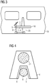
Fig. 3 zeigt einen Innenraum eines Schienenfahrzeugs in schematischer Darstellung und als Aufriss. Der Innenraum weist eine Sitzgruppe 18 auf, welche mit einer Innenwand 19 des Schienenfahrzeugs verbunden ist. Im unteren Bereich der Sitzgruppe 18 ist ein Stauraum 20 vorgesehen.
Die Sitzgruppe 18 weist im Bereich einer Sitzfläche 2 eines Sitzes 1 eine dritte beispielhafte Ausführungsvariante einer erfindungsgemäßen Haltevorrichtung auf. Die Haltevorrichtung umfasst einen Vorrichtungskörper 4, welcher einstückig mit dem Sitz 1 ausgebildet ist. In dem Vorrichtungskörper 4 ist eine Ausnehmung 5 vorgesehen, welche mit einem inFig. 1 gezeigten Haftkörper 6 ausgekleidet ist. - Über den Haftkörper 6 ist als Kontaktkörper eine Lenkstange 8 einer als Roller 9 ausgeführten Rollvorrichtung (die Lenkstange 8 ist somit Teil der Rollvorrichtung) kraftschlüssig bzw. reibschlüssig mit dem Vorrichtungskörper 4 verbunden. Der Roller 9 ist dadurch in der Haltevorrichtung fixiert und im Bereich des Stauraums 20 im unteren Bereich der Sitzgruppe 18 abgestellt.
Der Stauraum 20 weist eine Ladungssicherungseinrichtung auf, welche eine Ladungssicherungsschiene umfasst. Die Ladungssicherungsschiene ist einen Boden des Schienenfahrzeugs eingearbeitet und mit einem metallischen U-Profil ausgekleidet. In der Ladungssicherungsschiene sind Rollen des Rollers 9 eingeführt, wodurch dessen Stellplatz und dessen Ausrichtung parallel zu der Innenwand 19 definiert ist. Zwischen den Rollen und der Ladungssicherungsschiene ist ein leichter Reibschluss vorgesehen, wodurch unbeabsichtigte Bewegungen des Rollers 9 vermieden werden.
Erfindungsgemäß ist es denkbar, eine Mehrzahl an Ladungssicherungsschienen vorzusehen, beispielsweise je eine Ladungssicherungsschiene für jedes Paar von voneinander abgewandten Sitzplätzen der Sitzgruppe 18.
Erfindungsgemäß ist es weiterhin vorstellbar, dass die Ladungssicherungsschiene nicht parallel, sondern schräg zu der Innenwand 19 ausgerichtet ist. - Erfindungsgemäß können mit der Haltevorrichtung Roller 9 oder Elektroroller fixiert werden. Insbesondere eignen sich längliche, stab- oder stangenförmige Körper für eine Fixierung in der Haltevorrichtung.
- Die erfindungsgemäße Haltevorrichtung ist in dieser dritten beispielhaften Ausführungsvariante in dem Innenraum des Schienenfahrzeugs vorgesehen. Sie kann jedoch in Innenräumen unterschiedlicher Fahrzeuge eingesetzt sein, z.B. auch in Bussen wie Autobussen, O-Bussen, Elektrobussen etc.
- Weiterhin kann die Sitzgruppe 18 auch mehr als eine Ausnehmung 5 aufweisen, welche in günstiger Weise voneinander versetzt angeordnet sind, um mehrere in erfindungsgemäßen Haltevorrichtungen fixierte Roller 9 geschlichtet verstauen zu können.
- In
Fig. 4 ist eine Haltestange 21 eines Innenraums eines Schienenfahrzeugs schematisch, geschnitten und als Grundriss dargestellt.
Mit der Haltestange 21 ist ein Vorrichtungskörper 4 einer vierten beispielhaften Ausführungsvariante einer erfindungsgemäßen Haltevorrichtung verschweißt, d.h. stoffschlüssig verbunden. Der Vorrichtungskörper 4 weist eine mit einem Haftkörper 6 ausgekleidete Ausnehmung 5 auf, in welche als Kontaktkörper eine Lenkstange 8 eines inFig. 3 gezeigten Rollers 9, d.h. einer Rollvorrichtung, eingeführt ist. Der Kontaktkörper ist über den Haftkörper 6 kraftschlüssig bzw. reibschlüssig mit dem Vorrichtungskörper 4 verbunden.
Die Ausnehmung 5 und der Haftkörper 6 entsprechen konstruktiv und funktionell jener Ausführungsvariante einer erfindungsgemäßen Haltevorrichtung, welche inFig. 1 dargestellt ist. -
Fig. 5 zeigt eine Innenwand 19 eines Schienenfahrzeugs schematisch, geschnitten und als Grundriss. Mit der Innenwand 19 ist, in einen Innenraum des Schienenfahrzeugs hineinragend, ein Vorrichtungskörper 4 einer fünften beispielhaften Ausführungsvariante einer erfindungsgemäßen Haltevorrichtung über eine erste Schraube 22, eine zweite Schraube 23 sowie weitere Schrauben verbunden.
Der Vorrichtungskörper 4 weist eine mit einem Haftkörper 6 ausgekleidete Ausnehmung 5 auf, in welche als Kontaktkörper eine Lenkstange 8 eines inFig. 3 gezeigten Rollers 9, d.h. einer Rollvorrichtung, eingeführt ist. Der als Gummiwulst ausgeführte Haftkörper 6 ist im Bereich der Ausnehmung 5 mit dem Vorrichtungskörper 4 verklebt.
Der Kontaktkörper ist über den Haftkörper 6 kraftschlüssig bzw. reibschlüssig mit dem Vorrichtungskörper 4 verbunden. - Als Verriegelungsvorrichtung 11 weist die in
Fig. 5 gezeigte Haltevorrichtung eine Arretiernoppe 24 auf, welche als Verdickung des Haftkörpers 6 ausgebildet ist, d.h. einstückig mit dem Haftkörper 6 ausgeführt ist.
Bei einem Einführen des Kontaktkörpers in die Ausnehmung 5 und dessen Entfernung aus der Ausnehmung 5 muss ein Widerstand aufgrund der Arretiernoppe 24 überwunden werden, d.h. die Arretiernoppe 24 von dem Kontaktkörper durch Kraftaufwendung verformt bzw. eingedrückt werden. - Nach Einführen des Kontaktkörpers in die Ausnehmung 5 und Überwindung des Widerstands aufgrund der Arretiernoppe 24 ist der Kontaktkörper in der Haltevorrichtung arretiert. Erfindungsgemäß kann selbstverständlich auch mehr als eine Arretiernoppe 24 vorgesehen sein.
-
- 1
- Sitz
- 2
- Sitzfläche
- 3
- Lehne
- 4
- Vorrichtungskörper
- 5
- Ausnehmung
- 6
- Haftkörper
- 7
- Vorderseite
- 8
- Lenkstange
- 9
- Roller
- 10
- Rückseite
- 11
- Verriegelungsvorrichtung
- 12
- Erstes Arretiermittel
- 13
- Zweites Arretiermittel
- 14
- Erste Feder
- 15
- Zweite Feder
- 16
- Erste Führungshülse
- 17
- Zweite Führungshülse
- 18
- Sitzgruppe
- 19
- Innenwand
- 20
- Stauraum
- 21
- Haltestange
- 22
- Erste Schraube
- 23
- Zweite Schraube
- 24
- Arretiernoppe
Claims (21)
- Haltevorrichtung für einen Innenraum eines Fahrzeugs, insbesondere eines Schienenfahrzeugs oder eines Busses, dadurch gekennzeichnet, dass ein Vorrichtungskörper (4) vorgesehen ist, welcher zumindest eine Ausnehmung (5) aufweist, welche von dem Vorrichtungskörper (4) teilweise umgrenzt ist und in welche ein Kontaktkörper einführbar ist, welcher mit dem Vorrichtungskörper (4) kraftschlüssig verbindbar ist.
- Haltevorrichtung nach Anspruch 1, dadurch gekennzeichnet, dass der Vorrichtungskörper (4) einstückig mit einem Inneneinrichtungsteil des Fahrzeugs ausgebildet ist.
- Haltevorrichtung nach Anspruch 1, dadurch gekennzeichnet, dass der Vorrichtungskörper (4) mit einem Inneneinrichtungsteil des Fahrzeugs verbindbar ist.
- Haltevorrichtung nach Anspruch 2 oder 3, dadurch gekennzeichnet, dass das Inneneinrichtungsteil ein Sitz (1) oder eine Sitzgruppe (18) ist.
- Haltevorrichtung nach Anspruch 4, dadurch gekennzeichnet, dass die zumindest eine Ausnehmung (5) in einer Sitzfläche (2) vorgesehen ist.
- Haltevorrichtung nach einem der Ansprüche 2 bis 4, dadurch gekennzeichnet, dass das Inneneinrichtungsteil eine Lehne (3) ist.
- Haltevorrichtung nach einem der Ansprüche 4 bis 6, dadurch gekennzeichnet, dass der Sitz (1) oder die Sitzgruppe (18) unterhalb seiner Sitzfläche (2) oder ihrer Sitzflächen einen Stauraum (20) mit einer Ladungssicherungseinrichtung aufweist.
- Haltevorrichtung nach Anspruch 7, dadurch gekennzeichnet, dass die Ladungssicherungseinrichtung zumindest eine Ladungssicherungsschiene aufweist.
- Haltevorrichtung nach Anspruch 2 oder 3, dadurch gekennzeichnet, dass das Inneneinrichtungsteil eine Haltestange (21) ist.
- Haltevorrichtung nach Anspruch 2 oder 3, dadurch gekennzeichnet, dass das Inneneinrichtungsteil eine Innenwand (19) ist.
- Haltevorrichtung nach einem der Ansprüche 1 bis 10, dadurch gekennzeichnet, dass der Vorrichtungskörper (4) im Bereich der zumindest einen Ausnehmung (5) zumindest teilweise mit einem Haftkörper (6) ausgekleidet ist.
- Haltevorrichtung nach Anspruch 11, dadurch gekennzeichnet, dass der Haftkörper (6) zumindest teilweise magnetisch ausgeführt ist.
- Haltevorrichtung nach einem der Ansprüche 1 bis 10, dadurch gekennzeichnet, dass der Vorrichtungskörper (4) im Bereich der zumindest einen Ausnehmung (5) eine rutschhemmende Beschichtung aufweist.
- Haltevorrichtung nach einem der Ansprüche 1 bis 10, dadurch gekennzeichnet, dass der Vorrichtungskörper (4) im Bereich der zumindest einen Ausnehmung (5) zumindest teilweise magnetisch ausgeführt ist oder in der zumindest einen Ausnehmung (5) zumindest ein Magnet vorgesehen ist.
- Haltevorrichtung nach Anspruch 12 oder 14, dadurch gekennzeichnet, dass der Kontaktkörper im Kontaktbereich mit dem Haftkörper (6), dem Vorrichtungskörper (4) oder dem zumindest einen Magneten kugelförmig-konvex ausgebildet ist und der Haftkörper (6), der Vorrichtungskörper (4) oder der zumindest eine Magnet kugelförmig-konkav ausgebildet ist.
- Haltevorrichtung nach einem der Ansprüche 1 bis 15, dadurch gekennzeichnet, dass der Vorrichtungskörper (4) im Bereich der zumindest einen Ausnehmung (5) eine Verriegelungsvorrichtung (11) aufweist.
- Haltevorrichtung nach Anspruch 16, dadurch gekennzeichnet, dass die Verriegelungsvorrichtung (11) zumindest ein erstes Arretiermittel (12) aufweist, welches über eine erste Feder (14) mit dem Vorrichtungskörper (4) verbunden ist.
- Haltevorrichtung nach Anspruch 16, dadurch gekennzeichnet, dass die Verriegelungsvorrichtung (11) zumindest eine Arretiernoppe (24) aufweist.
- Haltevorrichtung nach einem der Ansprüche 1 bis 18, dadurch gekennzeichnet, dass die zumindest eine Ausnehmung (5) zumindest teilweise keilförmig ausgebildet ist.
- Haltevorrichtung nach einem der Ansprüche 1 bis 19, dadurch gekennzeichnet, dass die zumindest eine Ausnehmung (5) zumindest teilweise zylindrisch ausgebildet ist.
- Haltevorrichtung nach einem der Ansprüche 1 bis 20, dadurch gekennzeichnet, dass der Kontaktkörper Teil einer Rollvorrichtung, insbesondere eine Lenkstange (8) eines Rollers (9) ist.
Applications Claiming Priority (1)
| Application Number | Priority Date | Filing Date | Title |
|---|---|---|---|
| ATA50547/2019A AT522775B1 (de) | 2019-06-18 | 2019-06-18 | Haltevorrichtung für einen Innenraum eines Fahrzeugs |
Publications (2)
| Publication Number | Publication Date |
|---|---|
| EP3753798A1 true EP3753798A1 (de) | 2020-12-23 |
| EP3753798B1 EP3753798B1 (de) | 2024-11-20 |
Family
ID=71105287
Family Applications (1)
| Application Number | Title | Priority Date | Filing Date |
|---|---|---|---|
| EP20180360.8A Active EP3753798B1 (de) | 2019-06-18 | 2020-06-16 | Haltevorrichtung für einen innenraum eines fahrzeugs |
Country Status (2)
| Country | Link |
|---|---|
| EP (1) | EP3753798B1 (de) |
| AT (1) | AT522775B1 (de) |
Cited By (1)
| Publication number | Priority date | Publication date | Assignee | Title |
|---|---|---|---|---|
| CN115284989A (zh) * | 2022-07-29 | 2022-11-04 | 中车唐山机车车辆有限公司 | 一种车辆的折叠式腰靠及车辆 |
Citations (8)
| Publication number | Priority date | Publication date | Assignee | Title |
|---|---|---|---|---|
| DE29804320U1 (de) * | 1998-03-11 | 1998-05-07 | Deutsche Waggonbau AG, 12526 Berlin | Haltevorrichtung für Fahrräder, insbesondere zum Einbau in Nahverkehrsfahrzeugen |
| DE10061736A1 (de) * | 2000-12-07 | 2002-06-27 | Daimlerchrysler Rail Systems | Haltevorrichtung für Fahrräder |
| DE202004013092U1 (de) * | 2004-08-18 | 2004-11-04 | Brüderle, Uwe | Haltevorrichtung für Längskörper |
| DE102009004525A1 (de) | 2009-01-09 | 2010-08-05 | Bombardier Transportation Gmbh | Fangvorrichtung für einen Rollstuhl in einem Fahrzeug, insbesondere Schienenfahrzeug |
| DE102010005689A1 (de) * | 2010-01-25 | 2011-07-28 | Bröcker, Matthias, Dipl.-Des., 34125 | Fahrradhalteeinrichtung, insbesondere für öffentliche Verkehrsmittel |
| DE102011012903A1 (de) * | 2011-03-03 | 2012-09-06 | Daimler Ag | Sitz für ein Fahrzeug |
| EP2832628A1 (de) * | 2013-07-31 | 2015-02-04 | Bombardier Transportation GmbH | Innenausstattungsgegenstand zur Anordnung in Fahrzeugen des öffentlichen Verkehrs |
| US20180264984A1 (en) * | 2016-11-29 | 2018-09-20 | Nippon Sharyo, Ltd. | Bicycle retainer |
Family Cites Families (4)
| Publication number | Priority date | Publication date | Assignee | Title |
|---|---|---|---|---|
| DE1225513B (de) * | 1961-01-31 | 1966-09-22 | Fr Samia Soc A Responsabilite | Fahrradstaender zum Einstellen von Raedern mit unterschiedlicher Profilbreite |
| IL106546A0 (en) * | 1993-08-01 | 1993-12-08 | Zvi Rozenberg | Apparatus for a bicycle and a two wheel vehicle |
| EP0679567B1 (de) * | 1994-04-29 | 1998-11-25 | CAPITELVECCHIO S.r.l. | Parkvorrichtung für Zweiradfahrzeug |
| GB9620201D0 (en) * | 1996-09-27 | 1996-11-13 | Burns Matthew M | Bikestore |
-
2019
- 2019-06-18 AT ATA50547/2019A patent/AT522775B1/de not_active IP Right Cessation
-
2020
- 2020-06-16 EP EP20180360.8A patent/EP3753798B1/de active Active
Patent Citations (8)
| Publication number | Priority date | Publication date | Assignee | Title |
|---|---|---|---|---|
| DE29804320U1 (de) * | 1998-03-11 | 1998-05-07 | Deutsche Waggonbau AG, 12526 Berlin | Haltevorrichtung für Fahrräder, insbesondere zum Einbau in Nahverkehrsfahrzeugen |
| DE10061736A1 (de) * | 2000-12-07 | 2002-06-27 | Daimlerchrysler Rail Systems | Haltevorrichtung für Fahrräder |
| DE202004013092U1 (de) * | 2004-08-18 | 2004-11-04 | Brüderle, Uwe | Haltevorrichtung für Längskörper |
| DE102009004525A1 (de) | 2009-01-09 | 2010-08-05 | Bombardier Transportation Gmbh | Fangvorrichtung für einen Rollstuhl in einem Fahrzeug, insbesondere Schienenfahrzeug |
| DE102010005689A1 (de) * | 2010-01-25 | 2011-07-28 | Bröcker, Matthias, Dipl.-Des., 34125 | Fahrradhalteeinrichtung, insbesondere für öffentliche Verkehrsmittel |
| DE102011012903A1 (de) * | 2011-03-03 | 2012-09-06 | Daimler Ag | Sitz für ein Fahrzeug |
| EP2832628A1 (de) * | 2013-07-31 | 2015-02-04 | Bombardier Transportation GmbH | Innenausstattungsgegenstand zur Anordnung in Fahrzeugen des öffentlichen Verkehrs |
| US20180264984A1 (en) * | 2016-11-29 | 2018-09-20 | Nippon Sharyo, Ltd. | Bicycle retainer |
Cited By (1)
| Publication number | Priority date | Publication date | Assignee | Title |
|---|---|---|---|---|
| CN115284989A (zh) * | 2022-07-29 | 2022-11-04 | 中车唐山机车车辆有限公司 | 一种车辆的折叠式腰靠及车辆 |
Also Published As
| Publication number | Publication date |
|---|---|
| AT522775A4 (de) | 2021-01-15 |
| EP3753798B1 (de) | 2024-11-20 |
| AT522775B1 (de) | 2021-01-15 |
Similar Documents
| Publication | Publication Date | Title |
|---|---|---|
| WO2010145915A1 (de) | System und verfahren zum herstellen einer fahrzeugkabine | |
| DE102007038712A1 (de) | Befestigungsbeschlag | |
| DE102008060747A1 (de) | Bedarfsitz für ein Kraftfahrzeug | |
| DE102006009886A1 (de) | Verschiebbarer Ladeboden | |
| DE102013215063A1 (de) | Innenausstattungsgegenstand zur Anordnung in Fahrzeugen des öffentlichen Verkehrs | |
| DE102007063565A1 (de) | Kraftfahrzeugsitz | |
| EP3753798B1 (de) | Haltevorrichtung für einen innenraum eines fahrzeugs | |
| DE102007047755A1 (de) | Dachträgervorrichtung für ein Fahrzeug | |
| DE102018115776A1 (de) | Sitzgestellbefestigungsbaugruppe, Sitzgestell, Fahrzeugabschnitt und Fahrzeug mit einer Sitzgestellbefestigungsbaugruppe | |
| EP3865343A1 (de) | Fahrzeug zur personenbeförderung, mit wenigstens einer haltestange | |
| EP4289663B1 (de) | Fahrgastsitzanordnung für ein personentransportfahrzeug wie z.b. einen bus oder ein schienenfahrzeug | |
| DE102023211302A1 (de) | Sitzanordnung | |
| DE102017116824A1 (de) | Befestigungssystem zum Befestigen von Einrichtungsgegenständen an einem Fußboden einer Kabine eines Fahrzeugs | |
| AT518631B1 (de) | Gelenkfahrzeug | |
| DE102011120533A1 (de) | Fahrzeugsitz, Fahrzeug und Verfahren hierzu | |
| DE102009019014B4 (de) | Fahrzeugsitz, insbesondere Kraftfahrzeugsitz | |
| LU84819A1 (de) | Fahrzeugsitz fuer wenigstens zwei personen | |
| DE102014204934B3 (de) | Trenneinrichtung zur Abtrennung eines Laderaums von einem Fahrgastraum eines Kraftwagens | |
| DE102013000727B4 (de) | Vorrichtung zur lösbaren Befestigung von Einbauteilen | |
| DE102012010238A1 (de) | Fahrzeugsitz | |
| DE102013006931B4 (de) | Kraftfahrzeug | |
| DE19929036B4 (de) | Verstellbarer Sitz, insbesondere für die zweite oder dritte Sitzreihe eines Kraftfahrzeuges | |
| DE102019123436A1 (de) | Gehhilfe, Rollator oder dergleichen | |
| DE102018215040A1 (de) | Sitz für Fahrzeuge des öffentlichen Personennahverkehrs | |
| DE102007060934A1 (de) | Kraftfahrzeugsitz |
Legal Events
| Date | Code | Title | Description |
|---|---|---|---|
| PUAI | Public reference made under article 153(3) epc to a published international application that has entered the european phase |
Free format text: ORIGINAL CODE: 0009012 |
|
| STAA | Information on the status of an ep patent application or granted ep patent |
Free format text: STATUS: THE APPLICATION HAS BEEN PUBLISHED |
|
| AK | Designated contracting states |
Kind code of ref document: A1 Designated state(s): AL AT BE BG CH CY CZ DE DK EE ES FI FR GB GR HR HU IE IS IT LI LT LU LV MC MK MT NL NO PL PT RO RS SE SI SK SM TR |
|
| AX | Request for extension of the european patent |
Extension state: BA ME |
|
| STAA | Information on the status of an ep patent application or granted ep patent |
Free format text: STATUS: REQUEST FOR EXAMINATION WAS MADE |
|
| 17P | Request for examination filed |
Effective date: 20210618 |
|
| RBV | Designated contracting states (corrected) |
Designated state(s): AL AT BE BG CH CY CZ DE DK EE ES FI FR GB GR HR HU IE IS IT LI LT LU LV MC MK MT NL NO PL PT RO RS SE SI SK SM TR |
|
| STAA | Information on the status of an ep patent application or granted ep patent |
Free format text: STATUS: EXAMINATION IS IN PROGRESS |
|
| 17Q | First examination report despatched |
Effective date: 20230104 |
|
| GRAP | Despatch of communication of intention to grant a patent |
Free format text: ORIGINAL CODE: EPIDOSNIGR1 |
|
| STAA | Information on the status of an ep patent application or granted ep patent |
Free format text: STATUS: GRANT OF PATENT IS INTENDED |
|
| INTG | Intention to grant announced |
Effective date: 20240715 |
|
| GRAS | Grant fee paid |
Free format text: ORIGINAL CODE: EPIDOSNIGR3 |
|
| GRAA | (expected) grant |
Free format text: ORIGINAL CODE: 0009210 |
|
| STAA | Information on the status of an ep patent application or granted ep patent |
Free format text: STATUS: THE PATENT HAS BEEN GRANTED |
|
| AK | Designated contracting states |
Kind code of ref document: B1 Designated state(s): AL AT BE BG CH CY CZ DE DK EE ES FI FR GB GR HR HU IE IS IT LI LT LU LV MC MK MT NL NO PL PT RO RS SE SI SK SM TR |
|
| REG | Reference to a national code |
Ref country code: GB Ref legal event code: FG4D Free format text: NOT ENGLISH |
|
| REG | Reference to a national code |
Ref country code: CH Ref legal event code: EP |
|
| REG | Reference to a national code |
Ref country code: DE Ref legal event code: R096 Ref document number: 502020009768 Country of ref document: DE |
|
| REG | Reference to a national code |
Ref country code: IE Ref legal event code: FG4D Free format text: LANGUAGE OF EP DOCUMENT: GERMAN |
|
| REG | Reference to a national code |
Ref country code: LT Ref legal event code: MG9D |
|
| REG | Reference to a national code |
Ref country code: NL Ref legal event code: MP Effective date: 20241120 |
|
| PG25 | Lapsed in a contracting state [announced via postgrant information from national office to epo] |
Ref country code: PT Free format text: LAPSE BECAUSE OF FAILURE TO SUBMIT A TRANSLATION OF THE DESCRIPTION OR TO PAY THE FEE WITHIN THE PRESCRIBED TIME-LIMIT Effective date: 20250320 Ref country code: IS Free format text: LAPSE BECAUSE OF FAILURE TO SUBMIT A TRANSLATION OF THE DESCRIPTION OR TO PAY THE FEE WITHIN THE PRESCRIBED TIME-LIMIT Effective date: 20250320 Ref country code: HR Free format text: LAPSE BECAUSE OF FAILURE TO SUBMIT A TRANSLATION OF THE DESCRIPTION OR TO PAY THE FEE WITHIN THE PRESCRIBED TIME-LIMIT Effective date: 20241120 |
|
| PG25 | Lapsed in a contracting state [announced via postgrant information from national office to epo] |
Ref country code: FI Free format text: LAPSE BECAUSE OF FAILURE TO SUBMIT A TRANSLATION OF THE DESCRIPTION OR TO PAY THE FEE WITHIN THE PRESCRIBED TIME-LIMIT Effective date: 20241120 Ref country code: NL Free format text: LAPSE BECAUSE OF FAILURE TO SUBMIT A TRANSLATION OF THE DESCRIPTION OR TO PAY THE FEE WITHIN THE PRESCRIBED TIME-LIMIT Effective date: 20241120 |
|
| PG25 | Lapsed in a contracting state [announced via postgrant information from national office to epo] |
Ref country code: BG Free format text: LAPSE BECAUSE OF FAILURE TO SUBMIT A TRANSLATION OF THE DESCRIPTION OR TO PAY THE FEE WITHIN THE PRESCRIBED TIME-LIMIT Effective date: 20241120 |
|
| PG25 | Lapsed in a contracting state [announced via postgrant information from national office to epo] |
Ref country code: NO Free format text: LAPSE BECAUSE OF FAILURE TO SUBMIT A TRANSLATION OF THE DESCRIPTION OR TO PAY THE FEE WITHIN THE PRESCRIBED TIME-LIMIT Effective date: 20250220 |
|
| PG25 | Lapsed in a contracting state [announced via postgrant information from national office to epo] |
Ref country code: LV Free format text: LAPSE BECAUSE OF FAILURE TO SUBMIT A TRANSLATION OF THE DESCRIPTION OR TO PAY THE FEE WITHIN THE PRESCRIBED TIME-LIMIT Effective date: 20241120 Ref country code: GR Free format text: LAPSE BECAUSE OF FAILURE TO SUBMIT A TRANSLATION OF THE DESCRIPTION OR TO PAY THE FEE WITHIN THE PRESCRIBED TIME-LIMIT Effective date: 20250221 |
|
| PG25 | Lapsed in a contracting state [announced via postgrant information from national office to epo] |
Ref country code: PL Free format text: LAPSE BECAUSE OF FAILURE TO SUBMIT A TRANSLATION OF THE DESCRIPTION OR TO PAY THE FEE WITHIN THE PRESCRIBED TIME-LIMIT Effective date: 20241120 |
|
| PG25 | Lapsed in a contracting state [announced via postgrant information from national office to epo] |
Ref country code: RS Free format text: LAPSE BECAUSE OF FAILURE TO SUBMIT A TRANSLATION OF THE DESCRIPTION OR TO PAY THE FEE WITHIN THE PRESCRIBED TIME-LIMIT Effective date: 20250220 |
|
| PG25 | Lapsed in a contracting state [announced via postgrant information from national office to epo] |
Ref country code: SM Free format text: LAPSE BECAUSE OF FAILURE TO SUBMIT A TRANSLATION OF THE DESCRIPTION OR TO PAY THE FEE WITHIN THE PRESCRIBED TIME-LIMIT Effective date: 20241120 |
|
| PG25 | Lapsed in a contracting state [announced via postgrant information from national office to epo] |
Ref country code: DK Free format text: LAPSE BECAUSE OF FAILURE TO SUBMIT A TRANSLATION OF THE DESCRIPTION OR TO PAY THE FEE WITHIN THE PRESCRIBED TIME-LIMIT Effective date: 20241120 |
|
| PG25 | Lapsed in a contracting state [announced via postgrant information from national office to epo] |
Ref country code: EE Free format text: LAPSE BECAUSE OF FAILURE TO SUBMIT A TRANSLATION OF THE DESCRIPTION OR TO PAY THE FEE WITHIN THE PRESCRIBED TIME-LIMIT Effective date: 20241120 |
|
| PG25 | Lapsed in a contracting state [announced via postgrant information from national office to epo] |
Ref country code: RO Free format text: LAPSE BECAUSE OF FAILURE TO SUBMIT A TRANSLATION OF THE DESCRIPTION OR TO PAY THE FEE WITHIN THE PRESCRIBED TIME-LIMIT Effective date: 20241120 |
|
| PG25 | Lapsed in a contracting state [announced via postgrant information from national office to epo] |
Ref country code: SK Free format text: LAPSE BECAUSE OF FAILURE TO SUBMIT A TRANSLATION OF THE DESCRIPTION OR TO PAY THE FEE WITHIN THE PRESCRIBED TIME-LIMIT Effective date: 20241120 |
|
| PG25 | Lapsed in a contracting state [announced via postgrant information from national office to epo] |
Ref country code: CZ Free format text: LAPSE BECAUSE OF FAILURE TO SUBMIT A TRANSLATION OF THE DESCRIPTION OR TO PAY THE FEE WITHIN THE PRESCRIBED TIME-LIMIT Effective date: 20241120 |
|
| PG25 | Lapsed in a contracting state [announced via postgrant information from national office to epo] |
Ref country code: IT Free format text: LAPSE BECAUSE OF FAILURE TO SUBMIT A TRANSLATION OF THE DESCRIPTION OR TO PAY THE FEE WITHIN THE PRESCRIBED TIME-LIMIT Effective date: 20241120 |
|
| REG | Reference to a national code |
Ref country code: DE Ref legal event code: R097 Ref document number: 502020009768 Country of ref document: DE |
|
| PG25 | Lapsed in a contracting state [announced via postgrant information from national office to epo] |
Ref country code: SE Free format text: LAPSE BECAUSE OF FAILURE TO SUBMIT A TRANSLATION OF THE DESCRIPTION OR TO PAY THE FEE WITHIN THE PRESCRIBED TIME-LIMIT Effective date: 20241120 |
|
| PLBE | No opposition filed within time limit |
Free format text: ORIGINAL CODE: 0009261 |
|
| STAA | Information on the status of an ep patent application or granted ep patent |
Free format text: STATUS: NO OPPOSITION FILED WITHIN TIME LIMIT |
|
| 26N | No opposition filed |
Effective date: 20250821 |
|
| REG | Reference to a national code |
Ref country code: DE Ref legal event code: R119 Ref document number: 502020009768 Country of ref document: DE |
|
| REG | Reference to a national code |
Ref country code: CH Ref legal event code: H13 Free format text: ST27 STATUS EVENT CODE: U-0-0-H10-H13 (AS PROVIDED BY THE NATIONAL OFFICE) Effective date: 20260127 |
|
| PG25 | Lapsed in a contracting state [announced via postgrant information from national office to epo] |
Ref country code: ES Free format text: LAPSE BECAUSE OF FAILURE TO SUBMIT A TRANSLATION OF THE DESCRIPTION OR TO PAY THE FEE WITHIN THE PRESCRIBED TIME-LIMIT Effective date: 20241120 Ref country code: MC Free format text: LAPSE BECAUSE OF FAILURE TO SUBMIT A TRANSLATION OF THE DESCRIPTION OR TO PAY THE FEE WITHIN THE PRESCRIBED TIME-LIMIT Effective date: 20241120 |
|
| PG25 | Lapsed in a contracting state [announced via postgrant information from national office to epo] |
Ref country code: LU Free format text: LAPSE BECAUSE OF NON-PAYMENT OF DUE FEES Effective date: 20250616 |
|
| GBPC | Gb: european patent ceased through non-payment of renewal fee |
Effective date: 20250616 |
|
| REG | Reference to a national code |
Ref country code: BE Ref legal event code: MM Effective date: 20250630 |
|
| PG25 | Lapsed in a contracting state [announced via postgrant information from national office to epo] |
Ref country code: GB Free format text: LAPSE BECAUSE OF NON-PAYMENT OF DUE FEES Effective date: 20250616 |
|
| PG25 | Lapsed in a contracting state [announced via postgrant information from national office to epo] |
Ref country code: IE Free format text: LAPSE BECAUSE OF NON-PAYMENT OF DUE FEES Effective date: 20250616 Ref country code: DE Free format text: LAPSE BECAUSE OF NON-PAYMENT OF DUE FEES Effective date: 20260101 |
|
| PG25 | Lapsed in a contracting state [announced via postgrant information from national office to epo] |
Ref country code: BE Free format text: LAPSE BECAUSE OF NON-PAYMENT OF DUE FEES Effective date: 20250630 |
|
| PG25 | Lapsed in a contracting state [announced via postgrant information from national office to epo] |
Ref country code: FR Free format text: LAPSE BECAUSE OF NON-PAYMENT OF DUE FEES Effective date: 20250630 |
|
| PG25 | Lapsed in a contracting state [announced via postgrant information from national office to epo] |
Ref country code: CH Free format text: LAPSE BECAUSE OF NON-PAYMENT OF DUE FEES Effective date: 20250630 |