EP3750656A1 - Scie alternative - Google Patents
Scie alternative Download PDFInfo
- Publication number
- EP3750656A1 EP3750656A1 EP20179469.0A EP20179469A EP3750656A1 EP 3750656 A1 EP3750656 A1 EP 3750656A1 EP 20179469 A EP20179469 A EP 20179469A EP 3750656 A1 EP3750656 A1 EP 3750656A1
- Authority
- EP
- European Patent Office
- Prior art keywords
- cover
- shaft
- gearcase
- bearing
- reciprocating saw
- Prior art date
- Legal status (The legal status is an assumption and is not a legal conclusion. Google has not performed a legal analysis and makes no representation as to the accuracy of the status listed.)
- Withdrawn
Links
Images


Classifications
-
- B—PERFORMING OPERATIONS; TRANSPORTING
- B23—MACHINE TOOLS; METAL-WORKING NOT OTHERWISE PROVIDED FOR
- B23D—PLANING; SLOTTING; SHEARING; BROACHING; SAWING; FILING; SCRAPING; LIKE OPERATIONS FOR WORKING METAL BY REMOVING MATERIAL, NOT OTHERWISE PROVIDED FOR
- B23D51/00—Sawing machines or sawing devices working with straight blades, characterised only by constructional features of particular parts; Carrying or attaching means for tools, covered by this subclass, which are connected to a carrier at both ends
- B23D51/02—Sawing machines or sawing devices working with straight blades, characterised only by constructional features of particular parts; Carrying or attaching means for tools, covered by this subclass, which are connected to a carrier at both ends of beds; of guiding arrangements for work-tables or saw carriers; of frames
-
- B—PERFORMING OPERATIONS; TRANSPORTING
- B23—MACHINE TOOLS; METAL-WORKING NOT OTHERWISE PROVIDED FOR
- B23D—PLANING; SLOTTING; SHEARING; BROACHING; SAWING; FILING; SCRAPING; LIKE OPERATIONS FOR WORKING METAL BY REMOVING MATERIAL, NOT OTHERWISE PROVIDED FOR
- B23D49/00—Machines or devices for sawing with straight reciprocating saw blades, e.g. hacksaws
- B23D49/10—Hand-held or hand-operated sawing devices with straight saw blades
- B23D49/16—Hand-held or hand-operated sawing devices with straight saw blades actuated by electric or magnetic power or prime movers
- B23D49/162—Pad sawing devices
-
- B—PERFORMING OPERATIONS; TRANSPORTING
- B23—MACHINE TOOLS; METAL-WORKING NOT OTHERWISE PROVIDED FOR
- B23D—PLANING; SLOTTING; SHEARING; BROACHING; SAWING; FILING; SCRAPING; LIKE OPERATIONS FOR WORKING METAL BY REMOVING MATERIAL, NOT OTHERWISE PROVIDED FOR
- B23D51/00—Sawing machines or sawing devices working with straight blades, characterised only by constructional features of particular parts; Carrying or attaching means for tools, covered by this subclass, which are connected to a carrier at both ends
- B23D51/08—Sawing machines or sawing devices working with straight blades, characterised only by constructional features of particular parts; Carrying or attaching means for tools, covered by this subclass, which are connected to a carrier at both ends of devices for mounting straight saw blades or other tools
- B23D51/10—Sawing machines or sawing devices working with straight blades, characterised only by constructional features of particular parts; Carrying or attaching means for tools, covered by this subclass, which are connected to a carrier at both ends of devices for mounting straight saw blades or other tools for hand-held or hand-operated devices
-
- B—PERFORMING OPERATIONS; TRANSPORTING
- B23—MACHINE TOOLS; METAL-WORKING NOT OTHERWISE PROVIDED FOR
- B23D—PLANING; SLOTTING; SHEARING; BROACHING; SAWING; FILING; SCRAPING; LIKE OPERATIONS FOR WORKING METAL BY REMOVING MATERIAL, NOT OTHERWISE PROVIDED FOR
- B23D51/00—Sawing machines or sawing devices working with straight blades, characterised only by constructional features of particular parts; Carrying or attaching means for tools, covered by this subclass, which are connected to a carrier at both ends
- B23D51/16—Sawing machines or sawing devices working with straight blades, characterised only by constructional features of particular parts; Carrying or attaching means for tools, covered by this subclass, which are connected to a carrier at both ends of drives or feed mechanisms for straight tools, e.g. saw blades, or bows
-
- F—MECHANICAL ENGINEERING; LIGHTING; HEATING; WEAPONS; BLASTING
- F16—ENGINEERING ELEMENTS AND UNITS; GENERAL MEASURES FOR PRODUCING AND MAINTAINING EFFECTIVE FUNCTIONING OF MACHINES OR INSTALLATIONS; THERMAL INSULATION IN GENERAL
- F16H—GEARING
- F16H57/00—General details of gearing
- F16H57/02—Gearboxes; Mounting gearing therein
- F16H57/031—Gearboxes; Mounting gearing therein characterised by covers or lids for gearboxes
Definitions
- the present disclosure relates to a reciprocating saw and components, assemblies and methods of assembling the components.
- This may include a gearcase for a reciprocating saw and a method of assembling a reciprocating saw in a gearcase.
- the gearcase assembly requires sliding the shaft into the gearcase and assembling a yoke channel with screws after the shaft has been slid into the gearcase.
- the yoke channel may be attached to the shaft before the shaft is inserted into the gearcase.
- the assembly relies upon two screwed on covers to secure the shaft in place. This may allow dust and debris into an end near the blade clamp and may also provide weak points.
- aspects of the present disclosure relate to a reciprocating saw, a gearcase cover, a gearcase cover assembly, a gearcase assembly, and methods and components related thereto.
- a first aspect of the present invention provides a method of assembling a gearcase cover assembly of a reciprocating saw, according to Claim 1 of the appended claims.
- a second aspect of the invention provides a reciprocating saw according to Claim 8.
- a method of assembling a gearcase cover assembly of a reciprocating saw comprises providing a gearcase cover with an opening, preferably a cylindrical opening, and a receiving portion; providing a shaft with a yoke affixed to the shaft; inserting a first end of the shaft into the opening; and rotating the shaft such that a second end of the shaft sits in the receiving portion.
- the shaft further may further include a bearing affixed thereto.
- the gearcase cover may include a bearing receiving portion.
- the rotating the shaft may include rotating the shaft such that the bearing sits in the bearing receiving portion.
- the method may further include securing a bearing cover to the gearcase cover.
- the method may further comprise securing the bearing cover to the gearcase cover causes the shaft to be secured in the gearcase cover.
- the bearing cover may secure the bearing in the bearing receiving portion.
- the method may further include assembling a blade clamp assembly to the first end of the shaft.
- a reciprocating saw which includes a gearcase cover; and a shaft connected to the gearcase cover.
- the gearcase cover may be integrally formed to include a first end including an opening (preferably a substantially cylindrical opening preferably formed from a substantially cylindrical tube), and a second end including a receiving portion with an open portion opposite the receiving portion.
- the gearcase cover may be integrally formed via casting.
- the gearcase cover may be an integrally formed aluminum cast.
- the reciprocating saw may further include a securing cover at or adjacent to the open portion.
- the securing cover may be secured to the gearcase cover to secure the shaft in the gearcase cover.
- the securing cover may be secured to the gearcase cover via screws.
- the reciprocating saw may further include a yoke on the shaft.
- the yoke may be welded to the shaft.
- a reciprocating saw comprising a housing; a motor housed in the housing; a user-operable trigger configured to operate the motor; a blade clamp driven by the motor through a reciprocating shaft; and a gearcase adjacent to the motor.
- the gearcase includes a base and a gearcase cover.
- the gearcase preferably houses the shaft, a track roller bearing, a counterbalance and a pin that rotates with the track roller bearing.
- the gearcase cover preferably is integrally formed to include a first end including an opening (preferably a substantially cylindrical opening preferably formed from a substantially cylindrical tube), and a second end including a receiving portion with an open portion opposite the receiving portion.
- the gearcase cover may be integrally formed via casting.
- the gearcase cover may be an integrally formed aluminum cast.
- the reciprocating saw may further include a securing cover at or adjacent to the open portion.
- the securing cover may be secured to the gearcase cover.
- the securing cover may be secured to the gearcase cover via screws.
- the reciprocating saw may further include a yoke on the shaft.
- the yoke may be welded to the shaft.
- a reciprocating saw including a gearcase assembly.
- the gearcase assembly includes a gearcase cover and a reciprocating shaft.
- the reciprocating shaft is secured to the gearcase cover in at least two locations along the reciprocating shaft. In a first location the reciprocating shaft is secured by a securing plate. In the second location the reciprocating shaft is secured through an opening (preferably a substantially cylindrical opening) in the gearcase cover.
- the gearcase cover may be a single integrally made piece, such as a metal casting.
- the metal casting may be an aluminum casting.
- the method may include forming a gearcase cover with an open end and a closed end; providing a shaft with a yoke channel; inserting a first end of the shaft into the closed end of the gearcase cover; and rotating the shaft so that a second end of the shaft fits into the open end of the gearcase cover.
- the yoke channel may be welded onto the shaft.
- the method may further comprise securing a securing cover to the gearcase cover to secure the shaft in the gearcase cover.
- any feature, including any preferred feature, of any aspect of the invention may be a feature, including a preferred feature, of any other aspect of the invention.
- a trigger 13 is located on the handle 12 and depressing the switch causes the reciprocating saw 100 to operate.
- the trigger 13 may have a lock-off feature. It may also be a variable speed switch or have various variable speed controls.
- At a front of the reciprocating saw 100 there is a blade clamp 400.
- the blade clamp 400 is configured to hold a reciprocating saw blade, for example, such as the blade shown in U.S. Patent No. 8,210,081 , which is hereby incorporated by reference in its entirety.
- the reciprocating saw 100 also includes a shoe 450 to assist with guiding and cutting.
- Fig. 2 is a side view of the reciprocating saw 100 with part of the housing 10 removed so that the internals are visible.
- the reciprocating saw 100 includes a motor 30.
- the motor 30 drives the blade clamp 400 through a reciprocating saw shaft 300, discussed below.
- the housing holds a gearcase 250 which includes a gearcase cover assembly 200 and a base 230.
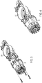
- Figs. 3 and 4 show perspective views of the motor 30 and gearcase base 230.
- Fig. 3 is an exploded view of the motor 30 and base 230 and Fig. 3 shows the motor 30 and base 230 assembled with one another.
- Figs. 5 and 6 illustrates a track roller bearing 231, a counter balance 232, and a pin 233 along with the motor 30 and base 230.
- Fig. 5 illustrates an exploded view
- Fig. 6 illustrates the assembled view.
- the track roller bearing 231 is driven by the motor 30 so that the track roller bearing 231 rotates.
- the pin 233 is connected to the track roller bearing 231 so that the pin 233 rotates along with the track roller bearing 231.
- the counter balance 232 helps to minimize vibration during use.
- Figs. 7-14 illustrate the gearcase cover assembly 200.
- the gearcase cover assembly includes a gearcase cover 210.
- the gearcase cover 210 is shown by itself in Fig. 9 .
- the gearcase cover 210 includes an opening 220 (which, as drawn is preferably generally cylindrical) through which the shaft 300 can project. Additionally, it has a rear receiving portion 235 which receives a rear end of the shaft 300 and a rear bearing receiving portion 236 which holds a rear bearing 320.
- the blade clamp 400 projects out of a front of the gear case cover 210.
- a rear end 301 of the shaft 300 fits into the rear receiving portion 235 of the cover 210.
- the rear bearing 320 fits into the rear bearing receiving portion 236.
- the bearing cover 330 fits over the rear receiving portion 235 to hold the rear bearing 320 in the cover 210.
- the cover 210 includes screw holes 332 and screws 331 secure the bearing cover 330 in place.
- the bearing cover 330 secures the rear bearing 320 in place and thus also secures the shaft 300 in place, and the bearing cover 330 may also be referred to as a securing cover or plate.
- the cover assembly 200 of Figs. 7 and 8 is attached to the base 230 and motor 30 assembly shown in Fig. 6 , as shown in Figs. 2 and 19 .
- the pin 233 engages yoke 310 that is fixed to the shaft 300.
- the yoke (or yoke channel) 310 is correspondingly moved forward and backwards. Since the shaft 300 is connected to the yoke 310 and the blade clamp 400 to the shaft 300, the shaft 300 and blade clamp 400 also move forward and backward in a reciprocal motion. A blade held by the blade clamp 400 thus also moves in a reciprocating motion and can cut a workpiece such as a piece of wood or a pipe.
- Fig. 9 illustrates the gearcase cover 210 alone.
- the gearcase cover 210 is formed integrally as a single piece.
- the gearcase cover 210 may be made of metal, for example aluminum. Additionally, the gearcase cover 210 may be made by casting. According to the exemplary embodiment, the gearcase cover 210 is an aluminum casting formed as a single piece.
- a forward end 212 of the gearcase cover 210 includes the opening 220, which is preferably generally cylindrical.
- the generally cylindrical opening 220 creates a generally cylindrical tube in the gearcase cover 210 through which the shaft 300 is inserted and extends. This tube prevents radial translation of the shaft 300. That is, the shaft 300 may rotate about its axis. Additionally, the shaft 300 may move axially forward or rearward until it is secured in those directions. However, the tube prevents radial translation of the shaft (i.e., the direction out of the page in Fig. 8 ).
- the cover 210 is open. Accordingly, as is shown in Fig. 10 , the shaft 300 with the yoke 310 and bearing 320 can be rotated towards the cover 210 into place. In particular, the shaft 300 may be rotated from the position in Fig. 10 to the position in Fig. 11 . During this rotation, the shaft 300 may move further into or out of the opening 220, though typically the shaft would move further into the opening 220 if there is any such movement.
- the gearcase cover 210 can be considered closed at the forward end 212 and open at and adjacent to the rear end 213.
- the cast aluminum tube provides greater strength than the bearing cover 330. Additionally, the cast aluminum generally cylindrical tube may prevent dust or debris from entering the area. This may be important at the forward end as it is closest to the blade clamp 400 which will hold a reciprocating saw blade for cutting. There may be significant forces on this area of the shaft 300 as the shaft 330 reciprocates. Additionally, any dust or debris may interfere with reciprocation of the shaft 300.
- the open end near the rear end 213 allows for ease of assembly.
- the yoke 310 to be attached to the shaft 300 (such as by welding) before the shaft 300 is assembled into the gearcase cover 210.
- the rear bearing 320 to be assembled onto the shaft 300 before the shaft is assembled into the gearcase cover 210.
- the gearcase covers included either two closed portions which required a sliding shaft assembly and that the yoke be secured to the shaft after the shaft was assembled to a gearcase cover; or two open portions which did not provide for the structural strength provided by the tube of the exemplary embodiment of the present invention.
- the combination of open and closed portions of the exemplary embodiment of the present invention provides both strength and ease of assembly.
- Fig. 9 illustrates the cover 210.
- the yoke 310 and the rear bearing 320 are assembled onto the shaft 300 before the shaft 300 is connected to the cover 210.
- a forward end 302 ( Fig. 13 ) of the shaft 300 is inserted into the opening 220 of the cover 210.
- the opening 220 is a preferably a generally cylindrical through hole.
- the forward end 302 of the shaft 300 projects through the opening 220.
- the shaft 300 is then rotated towards the cover 210 from the position shown in Fig. 10 to the position shown in Fig. 11 such that the rear end 301 of the shaft 300 sits in the rear receiving portion 235, the rear bearing 320 sits in rear bearing receiving portion 236, and the yoke 310 is aligned in the cover 210.
- the bearing cover 330 can be placed over the rear bearing 320 and screwed into place with screws 331 that project through holes in the bearing cover 330 into screwholes 232.
- the bearing cover 330 is shown secured in place in, for example, Figs. 8 and 15 .
- a forward bearing 321 can then be inserted over the forward end 302 of the shaft 300 into the opening 220 through the forward end of the opening.
- the forward bearing 321 is show in place in Fig. 14 .
- a locking assembly 360 can be secured over the forward bearing 321 to lock the forward bearing 321 in place.
- the locking assembly 360 is shown in an exploded view in Fig. 14 and in the assembled position in Fig. 15 .
- the locking assembly 360 includes a seal 361, felt 362 and a plate 363. Screws 364 secure the seal 361, felt 362 and plate 363.
- the seal 361 may be made of rubber or plastic, for example.
- the plate 363 may be made of metal, for example.
- the blade clamp 400 mechanism may be assembled to the forward end 302 of the shaft 300.
- the components of the blade clamp mechanism 400 are shown in Fig. 16 , and consist of a collar rotation pin 401, blade retention pin 402, blade sleeve 403, torsion spring 404, cam collar 405 and spiral ring 406.
- the cover assembly 200 is complete and is ready to be attached to the base 230 and motor 30.
- Fig. 17 illustrates the cover assembly 200 ready to be assembled with the base 230 and Fig. 18 shows the cover assembly 200 assembled with the base 230. As shown in Fig. 17 , the cover assembly 200 may be assembled over the top of the base 230 and attached to the base 230 with screws 371. Fig. 18 illustrates it as assembled.
- Fig. 19 then shows that two sides of the housing 10 are screwed together to assemble the reciprocating saw 100.
Landscapes
- Engineering & Computer Science (AREA)
- Mechanical Engineering (AREA)
- General Engineering & Computer Science (AREA)
- Sawing (AREA)
Applications Claiming Priority (1)
| Application Number | Priority Date | Filing Date | Title |
|---|---|---|---|
| US201962860414P | 2019-06-12 | 2019-06-12 |
Publications (1)
| Publication Number | Publication Date |
|---|---|
| EP3750656A1 true EP3750656A1 (fr) | 2020-12-16 |
Family
ID=71092395
Family Applications (1)
| Application Number | Title | Priority Date | Filing Date |
|---|---|---|---|
| EP20179469.0A Withdrawn EP3750656A1 (fr) | 2019-06-12 | 2020-06-11 | Scie alternative |
Country Status (2)
| Country | Link |
|---|---|
| US (2) | US11738397B2 (fr) |
| EP (1) | EP3750656A1 (fr) |
Citations (7)
| Publication number | Priority date | Publication date | Assignee | Title |
|---|---|---|---|---|
| US2639737A (en) * | 1948-07-03 | 1953-05-26 | Harold S Forsberg | Motor driven reciprocating saw |
| US4238884A (en) * | 1979-06-19 | 1980-12-16 | Black & Decker Inc. | Orbital jig saw |
| DE19804706A1 (de) * | 1997-02-25 | 1998-08-27 | Scintilla Ag | Handgeführte Stichsägemaschine |
| EP1188505A2 (fr) * | 2000-09-19 | 2002-03-20 | Makita Corporation | Outils de coupe à mouvement de va-et-vient |
| US20060260141A1 (en) * | 2001-12-18 | 2006-11-23 | Black & Decker, Inc. | Bearing for a reciprocating shaft of a reciprocating saw |
| US8210081B2 (en) | 2007-06-12 | 2012-07-03 | Irwin Industrial Tool Company | Reciprocating saw blade having variable-height teeth and related method |
| EP3147058A1 (fr) * | 2014-05-23 | 2017-03-29 | Hitachi Koki Co., Ltd. | Outil à mouvement alternatif |
Family Cites Families (42)
| Publication number | Priority date | Publication date | Assignee | Title |
|---|---|---|---|---|
| US2704941A (en) * | 1952-04-03 | 1955-03-29 | Black & Decker Mfg Co | Power driven reciprocating tool |
| CH643130A5 (de) | 1980-02-13 | 1984-05-30 | Arnegger Richard E | Handgeraet von langgestreckter form, insbesondere fuer chirurgische eingriffe, und verfahren zu dessen herstellung. |
| US4474077A (en) * | 1982-02-01 | 1984-10-02 | Black & Decker Inc. | Housing retaining means for portable power tools and method of assembly therefor |
| US5079844A (en) | 1990-11-13 | 1992-01-14 | Milwaukee Electric Tool Corporation | Counterbalanced reciprocating mechanism |
| DE69510783T2 (de) | 1994-04-12 | 1999-12-02 | Porter Cable Corp | Schnellwechselsägeblattspannvorrichtung, bedienbar ohne zusätzliches werkzeug, für hin- und hergehende sägen |
| WO1997031745A2 (fr) | 1996-03-01 | 1997-09-04 | Milwaukee Electric Tool Corporation | Mecanisme de blocage de lame sans clavette |
| US6725548B1 (en) | 1996-03-01 | 2004-04-27 | Milwaukee Electric Tool Corporation | Keyless blade clamp mechanism |
| JP3431497B2 (ja) | 1998-05-13 | 2003-07-28 | 株式会社マキタ | 電動工具のシール機構 |
| EP0970771A3 (fr) | 1998-07-10 | 2000-05-03 | Porter-Cable Corporation | Dispositif de serrage de lame de scie sauteuse à élément de serrage actionné par came |
| US6209208B1 (en) | 1998-10-09 | 2001-04-03 | Milwaukee Electric Tool Corporarion | Keyless blade clamp mechanism |
| DE29905088U1 (de) | 1999-03-19 | 1999-06-24 | Kress Elektrik Gmbh & Co | Säge |
| US6568089B1 (en) | 1999-06-04 | 2003-05-27 | Porter-Cable/Delta | Reciprocating saw having compact configuration and independent stability |
| JP3995895B2 (ja) | 2000-05-16 | 2007-10-24 | 株式会社マキタ | 往復動切断工具のブレード取り付け装置 |
| US6735876B2 (en) | 2001-03-01 | 2004-05-18 | Makita Corporation | Blade clamps suitable for reciprocating power tools |
| CN1224484C (zh) | 2002-05-27 | 2005-10-26 | 苏州宝时得电动工具有限公司 | 往复电动工具 |
| US7040023B2 (en) | 2002-11-25 | 2006-05-09 | Eastway Fair Company Limited | Toolless blade holder for a reciprocating tool |
| US20040163264A1 (en) | 2003-02-21 | 2004-08-26 | Simonz John C. | Hand saw |
| US7871080B2 (en) | 2004-01-16 | 2011-01-18 | Robert Bosch Gmbh | Tool-less blade clamping apparatus for a reciprocating tool |
| US7303495B2 (en) * | 2004-04-27 | 2007-12-04 | General Motors Corporation | Continuously variable transmission case cover |
| US7107690B2 (en) | 2004-05-24 | 2006-09-19 | Choon Nang Electrical Appliance Mfy., Ltd. | Electric cutting tool |
| DE102004042026A1 (de) | 2004-08-31 | 2006-03-02 | Robert Bosch Gmbh | Spannvorrichtung zum werkzeuglosen Einspannen eines Sägeblatts |
| EP1661652A1 (fr) | 2004-11-25 | 2006-05-31 | Jiangsu Golden Harbour Enterprise Ltd. | Dispositif de serrage de lame de scie pour une scie alternative |
| DE102006043682A1 (de) | 2006-09-18 | 2008-03-27 | Robert Bosch Gmbh | Einspannvorrichtung für eine Hubsägemaschine |
| CN200995304Y (zh) | 2007-01-16 | 2007-12-26 | 南京德朔实业有限公司 | 一种锯片快速夹紧装置 |
| SE531224C2 (sv) | 2007-03-30 | 2009-01-20 | Seco Tools Ab | Verktyg med utbytbar spets |
| DE102007026444A1 (de) | 2007-06-06 | 2008-12-11 | Robert Bosch Gmbh | Handhubsägemaschine mit Spannvorrichtung für ein hin- und herbewegbares Werkzeug, insbesondere Hubsägeblatt |
| CN101396749B (zh) | 2007-09-27 | 2011-03-16 | 车王电子股份有限公司 | 刀锯机的刀锯夹持装置 |
| CN201295796Y (zh) | 2008-03-28 | 2009-08-26 | 南京德朔实业有限公司 | 一种往复锯 |
| US8181973B2 (en) | 2008-05-05 | 2012-05-22 | Robert Bosch Gmbh | Clamping apparatus for a reciprocating tool |
| CN101676055B (zh) | 2008-09-19 | 2011-09-21 | 车王电子股份有限公司 | 刀锯机的刀锯接头 |
| GB2472893B (en) * | 2009-07-23 | 2012-12-26 | Milwaukee Electric Tool Corp | Reciprocating saw |
| US8307910B2 (en) | 2010-04-07 | 2012-11-13 | Robert Bosch Gmbh | Drive mechanism for a reciprocating tool |
| CN102248221B (zh) | 2010-05-18 | 2013-08-21 | 南京德朔实业有限公司 | 一种锯片夹紧装置 |
| JP5558214B2 (ja) | 2010-06-08 | 2014-07-23 | 株式会社マキタ | 往復動切断工具のブレード取り付け装置 |
| AU2012250943A1 (en) | 2011-05-04 | 2013-11-28 | Stryker Corporation | Surgical sagittal saw with a drive assembly capable of displacing the attached blade in a crossed loop pattern |
| DE102011080445B4 (de) | 2011-08-04 | 2015-12-31 | Metabowerke Gmbh | Handgeführte Säge sowie Blattspannmechanismus hierfür |
| CN103203497B (zh) | 2012-01-16 | 2017-05-03 | 博世电动工具(中国)有限公司 | 锯片夹持装置 |
| US9156097B2 (en) | 2012-03-20 | 2015-10-13 | Milwaukee Electric Tool Corporation | Reciprocating saw blade clamp |
| JP6584121B2 (ja) * | 2015-04-17 | 2019-10-02 | 株式会社マキタ | 往復動工具 |
| TWM537946U (zh) | 2016-06-20 | 2017-03-11 | Lu Can-Yang | 往復式工具結構 |
| US20180126470A1 (en) | 2016-11-10 | 2018-05-10 | Milwaukee Electric Tool Corporation | Blade clamp for a reciprocating power tool |
| WO2018221105A1 (fr) * | 2017-05-31 | 2018-12-06 | 工機ホールディングス株式会社 | Outil à mouvement alternatif |
-
2020
- 2020-06-08 US US16/895,514 patent/US11738397B2/en active Active
- 2020-06-11 EP EP20179469.0A patent/EP3750656A1/fr not_active Withdrawn
-
2022
- 2022-07-25 US US17/872,615 patent/US11759873B2/en active Active
Patent Citations (7)
| Publication number | Priority date | Publication date | Assignee | Title |
|---|---|---|---|---|
| US2639737A (en) * | 1948-07-03 | 1953-05-26 | Harold S Forsberg | Motor driven reciprocating saw |
| US4238884A (en) * | 1979-06-19 | 1980-12-16 | Black & Decker Inc. | Orbital jig saw |
| DE19804706A1 (de) * | 1997-02-25 | 1998-08-27 | Scintilla Ag | Handgeführte Stichsägemaschine |
| EP1188505A2 (fr) * | 2000-09-19 | 2002-03-20 | Makita Corporation | Outils de coupe à mouvement de va-et-vient |
| US20060260141A1 (en) * | 2001-12-18 | 2006-11-23 | Black & Decker, Inc. | Bearing for a reciprocating shaft of a reciprocating saw |
| US8210081B2 (en) | 2007-06-12 | 2012-07-03 | Irwin Industrial Tool Company | Reciprocating saw blade having variable-height teeth and related method |
| EP3147058A1 (fr) * | 2014-05-23 | 2017-03-29 | Hitachi Koki Co., Ltd. | Outil à mouvement alternatif |
Also Published As
| Publication number | Publication date |
|---|---|
| US11738397B2 (en) | 2023-08-29 |
| US11759873B2 (en) | 2023-09-19 |
| US20220355400A1 (en) | 2022-11-10 |
| US20200391311A1 (en) | 2020-12-17 |
Similar Documents
| Publication | Publication Date | Title |
|---|---|---|
| EP2090393B1 (fr) | Outil électrique alternatif | |
| EP2785485B1 (fr) | Machine de sciage en va-et-vient articulee | |
| US7814666B2 (en) | Linkage drive mechanism for a reciprocating tool | |
| US6625892B2 (en) | Reciprocating cutting tools | |
| US7191847B2 (en) | Drive for a motor-driven hand-held tool | |
| US7254892B2 (en) | Support mechanism for a reciprocating tool | |
| EP2384860B1 (fr) | Carter pour un outil électrique | |
| EP3778085B1 (fr) | Dispositif de montage de lame de scie alternative et scie alternative | |
| US8813377B2 (en) | Reciprocating cutting tools | |
| US20030051352A1 (en) | Reciprocating saw with flush blade | |
| JP2015100899A (ja) | 作業工具 | |
| US20210213548A1 (en) | Reciprocating saw | |
| CN111975720B (zh) | 电动工具 | |
| WO2021010136A1 (fr) | Outil électrique | |
| EP3750656A1 (fr) | Scie alternative | |
| EP2527071A1 (fr) | Outil de coupe avec dispositif antipoussière | |
| JP7103002B2 (ja) | 切断機 | |
| US20210129311A1 (en) | Universal Chisel Attachment | |
| JP6801406B2 (ja) | 往復動工具及び往復動工具の組立方法 | |
| US11872646B2 (en) | Reciprocating tool | |
| WO2024024248A1 (fr) | Machine de travail | |
| CN110732726A (zh) | 便携式切割机 | |
| US20190358720A1 (en) | Saw blade quick release mechanism for sawing tool and the sawing tool using the same | |
| CN115673417A (zh) | 往复运动切割工具 | |
| CN114851138A (zh) | 冲击工具 |
Legal Events
| Date | Code | Title | Description |
|---|---|---|---|
| PUAI | Public reference made under article 153(3) epc to a published international application that has entered the european phase |
Free format text: ORIGINAL CODE: 0009012 |
|
| STAA | Information on the status of an ep patent application or granted ep patent |
Free format text: STATUS: THE APPLICATION HAS BEEN PUBLISHED |
|
| AK | Designated contracting states |
Kind code of ref document: A1 Designated state(s): AL AT BE BG CH CY CZ DE DK EE ES FI FR GB GR HR HU IE IS IT LI LT LU LV MC MK MT NL NO PL PT RO RS SE SI SK SM TR |
|
| AX | Request for extension of the european patent |
Extension state: BA ME |
|
| STAA | Information on the status of an ep patent application or granted ep patent |
Free format text: STATUS: THE APPLICATION IS DEEMED TO BE WITHDRAWN |
|
| 18D | Application deemed to be withdrawn |
Effective date: 20210617 |