EP3747606B1 - Rotary electric shaver - Google Patents
Rotary electric shaver Download PDFInfo
- Publication number
- EP3747606B1 EP3747606B1 EP20175759.8A EP20175759A EP3747606B1 EP 3747606 B1 EP3747606 B1 EP 3747606B1 EP 20175759 A EP20175759 A EP 20175759A EP 3747606 B1 EP3747606 B1 EP 3747606B1
- Authority
- EP
- European Patent Office
- Prior art keywords
- blade
- external
- inner blade
- internal
- outer blade
- Prior art date
- Legal status (The legal status is an assumption and is not a legal conclusion. Google has not performed a legal analysis and makes no representation as to the accuracy of the status listed.)
- Active
Links
- 210000004209 hair Anatomy 0.000 claims description 55
- 230000002093 peripheral effect Effects 0.000 claims description 15
- 230000002349 favourable effect Effects 0.000 description 10
- 238000003754 machining Methods 0.000 description 5
- 239000007769 metal material Substances 0.000 description 5
- 239000000956 alloy Substances 0.000 description 4
- 229910045601 alloy Inorganic materials 0.000 description 4
- 239000002184 metal Substances 0.000 description 4
- 238000005452 bending Methods 0.000 description 3
- 239000000463 material Substances 0.000 description 3
- 239000011347 resin Substances 0.000 description 3
- 229920005989 resin Polymers 0.000 description 3
- 230000005540 biological transmission Effects 0.000 description 2
- 230000004048 modification Effects 0.000 description 2
- 238000012986 modification Methods 0.000 description 2
- 238000000465 moulding Methods 0.000 description 2
- 230000000694 effects Effects 0.000 description 1
- 238000003780 insertion Methods 0.000 description 1
- 230000037431 insertion Effects 0.000 description 1
Images


Classifications
-
- B—PERFORMING OPERATIONS; TRANSPORTING
- B26—HAND CUTTING TOOLS; CUTTING; SEVERING
- B26B—HAND-HELD CUTTING TOOLS NOT OTHERWISE PROVIDED FOR
- B26B19/00—Clippers or shavers operating with a plurality of cutting edges, e.g. hair clippers, dry shavers
- B26B19/14—Clippers or shavers operating with a plurality of cutting edges, e.g. hair clippers, dry shavers of the rotary-cutter type; Cutting heads therefor; Cutters therefor
- B26B19/141—Details of inner cutters having their axes of rotation perpendicular to the cutting surface
-
- B—PERFORMING OPERATIONS; TRANSPORTING
- B26—HAND CUTTING TOOLS; CUTTING; SEVERING
- B26B—HAND-HELD CUTTING TOOLS NOT OTHERWISE PROVIDED FOR
- B26B19/00—Clippers or shavers operating with a plurality of cutting edges, e.g. hair clippers, dry shavers
- B26B19/14—Clippers or shavers operating with a plurality of cutting edges, e.g. hair clippers, dry shavers of the rotary-cutter type; Cutting heads therefor; Cutters therefor
- B26B19/143—Details of outer cutters
-
- B—PERFORMING OPERATIONS; TRANSPORTING
- B26—HAND CUTTING TOOLS; CUTTING; SEVERING
- B26B—HAND-HELD CUTTING TOOLS NOT OTHERWISE PROVIDED FOR
- B26B19/00—Clippers or shavers operating with a plurality of cutting edges, e.g. hair clippers, dry shavers
- B26B19/14—Clippers or shavers operating with a plurality of cutting edges, e.g. hair clippers, dry shavers of the rotary-cutter type; Cutting heads therefor; Cutters therefor
- B26B19/145—Cutters being movable in the cutting head
-
- B—PERFORMING OPERATIONS; TRANSPORTING
- B26—HAND CUTTING TOOLS; CUTTING; SEVERING
- B26B—HAND-HELD CUTTING TOOLS NOT OTHERWISE PROVIDED FOR
- B26B19/00—Clippers or shavers operating with a plurality of cutting edges, e.g. hair clippers, dry shavers
- B26B19/38—Details of, or accessories for, hair clippers, or dry shavers, e.g. housings, casings, grips, guards
- B26B19/42—Details of, or accessories for, hair clippers, or dry shavers, e.g. housings, casings, grips, guards providing for straightening the hair to be cut, e.g. by means of bristles; providing for tensioning the skin, e.g. by means of rollers, ledges
Definitions
- the present invention relates to a rotary electric shaver.
- a rotary electric shaver which includes an outer blade having a plurality of hair inlet holes on a shaving surface, and a rotationally driven inner blade having a plurality of small blades coming into sliding contact with a rear surface of the shaving surface.
- the rotary electric shaver cuts hairs entering the hair inlet holes by using the small blades (refer to PTL 1: JP-A-55-158082 ).
- the shaving surface of the outer blade is formed in an annular shape in a plan view. Accordingly, there is a disadvantage in that the hairs cannot be caught at a position radially inward of the shaving surface.
- a rotary electric shaver which includes another shaving surface at the position radially inward of the shaving surface, in addition to the shaving surface having the annular shape in a plan view (refer to PTL 2: JP-A-55-158083 ).
- the hairs can also be caught at the position radially inward of the shaving surface. Therefore, picking ability of the hairs can be improved.
- a further example of related prior art is given by the patent documentation WO2006/048799 .
- the rotary electric shaver disclosed as an example in PTL 2 adopts the following configuration for alignment and support of a central outer blade disposed radially inward of the outer blade having the annular shaving surface and the inner blade to be combined with the central outer blade.
- the configuration is adopted as follows.
- An outer blade stator is disposed at a radial center of the central outer blade, and an inner blade base is fixed to the outer blade stator so that both axes coincide with each other.
- the axes of the central outer blade and the corresponding inner blade can coincide with each other. Therefore, hair cutting performance (hair cutting quality) can be favorably improved.
- the central outer blade is configured so that a recessed location for engaging the outer blade stator is disposed at a radial center position of the shaving surface. Therefore, there is the following disadvantage. Since the recessed location (that is, a recessed cavity) is present on the shaving surface of the central outer blade, a sense of touch is worsened, and an area for catching the hairs is reduced. There is another disadvantage in that a configuration is complicated due to the increased number of components and machining man-hours.
- one or more aspects of the present invention are directed to a simply configured rotary electric shaver which can compatibly achieve favorable hair cutting quality and a favorable sense of touch when hairs are cut, and which can further improve picking ability and deep shaving ability.
- examples of the hairs include beards, mustache, whisker, and the like.
- a rotary electric shaver including an external outer blade having a plurality of hair inlet holes on an annular shaving surface in a plan view, an internal outer blade having a plurality of hair inlet holes on a disk-shaped shaving surface in a plan view and arranged radially inward of the external outer blade, a rotationally driven external inner blade having a plurality of small blades coming into sliding contact with a rear surface of the shaving surface of the external outer blade, a rotationally driven internal inner blade having a plurality of small blades coming into sliding contact with a rear surface of the shaving surface of the internal outer blade, an external inner blade rest base to which the external inner blade is fixed, and an internal inner blade rest base to which the internal inner blade is fixed and which is supported by the external inner blade rest base.
- the external outer blade has a cylindrical guide ring integrally or separately formed on an inner peripheral side of an inner wall portion.
- the external inner blade has a plurality of guides which come into sliding contact with an inner peripheral surface of the guide ring so as to align with the external outer blade in the radial direction.
- the embodiment of the present invention it is possible to compatibly achieve favorable hair cutting quality and a favorable sense of touch when hairs are cut, and it is possible to further improve picking ability and deep shaving ability. It is possible to realize a simple configuration having a small number of components and machining man-hours.
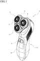
- Fig. 1 is a schematic view (perspective view) illustrating an example of a rotary electric shaver 1 according to the present embodiment.
- the same reference numerals will be assigned to members having the same functions, and the repeated description thereof may be omitted in some cases.
- a configuration in which three sets of blade units 4 are arranged in a head unit 3 held by a main body 2 will be described as an example.
- the blade unit 4 according to the present embodiment is configured to include an outer blade set 5, an external inner blade set 6, and an internal inner blade set 7 (to be described later).
- Fig. 2 illustrates a sectional view of the head unit 3 (sectional view in a portion of one blade unit 4).
- Fig. 3 illustrates a front sectional view (schematic view) of the blade unit 4.
- Fig. 4 illustrates a plan view (schematic view in which a shaving surface is not illustrated to facilitate understanding of an internal structure).
- Fig. 5 illustrates an exploded perspective view (schematic view).
- the present embodiment is an example in a case where three sets of blade units are provided. However, the present embodiment is not limited thereto.
- the main body 2 includes a substantially columnar case 10.
- the case 10 internally accommodates a drive source (electric motor as an example), a battery, and a control circuit board (all not illustrated).
- a power switch 11 is attached to a front surface of the case 10.
- the head unit 3 includes a head case 13 connected to and held by an upper portion of the case 10 of the main body 2, and an outer blade frame 14 fitted to the head case 13 from above, and an inner blade drive shaft 12 accommodated in an inner bottom portion of the head case 13. Furthermore, the head unit 3 includes three sets of an outer blade case 15 fitted to the outer blade frame 14 and a blade unit 4 held to be slightly movable and swingable in an axial direction with respect to the outer blade case 15. The three sets of the blade unit 4 are disposed in a triangular shape as an example. An axial movement amount of the blade unit 4 with respect to the outer blade case 15 (here, specified as an axial movement amount of the external outer blade 20) is set to approximately 0.5 to 1.5 mm, as an example.
- the respective outer blade cases 15 are configured to be movable in a seesaw shape with respect to the outer blade frame 14 while interlocking with each other. In this manner, an upper surface 3a of the head unit 3 can deform between a convex surface state and a concave surface state.
- Fig. 6 illustrates a perspective view (schematic view) of the outer blade set 5.
- the outer blade set 5 is configured to include an external outer blade 20 having a plurality of hair inlet holes (first hair inlet holes) 22 on an annular shaving surface 20 a in a plan view, and an internal outer blade 30 having a plurality of hair inlet holes (second hair inlet holes) 32 on a disk-shaped shaving surface 30a in a plan view and arranged radially inward of the external outer blade 20.
- the external outer blade 20 and the internal outer blade 30 are respectively formed as an integral structure (one component) by using a flat metal plate made of a stainless alloy and performing die cutting and bending using press working.
- the external outer blade 20 is configured to have an outer wall portion 20c and an inner wall portion 20d which respectively extend downward from edge portions of the shaving surface 20a.
- the hair inlet hole (first hair inlet hole) 22 disposed on the shaving surface 20a is formed as a through-hole extending from the shaving surface 20a to a rear surface 20b. According to this configuration, it is possible to obtain an action of cutting the hairs entering the hair inlet hole 22 by interposing the hairs between a lower end portion thereof and a distal end portion (blade edge 42a) of the small blade 42 of the external inner blade 40.
- the hair inlet hole 22 can adopt various shapes such as a slit shape (elongated hole shape), a round hole shape, and a rectangular hole shape, or a combination thereof.
- a configuration is adopted as follows.
- a radially curved slit-shaped hole 22A extending from an inner edge to an outer edge of the shaving surface 20a and a radially curved slit-shaped hole 22B extending from the center to the outer edge of the shaving surface 20a are alternately aligned in a circumferential direction.
- the external outer blade 20 is configured so that the inner wall portion 20d is discontinuous in the circumferential direction, that is, to have a plate shape (planar or curved surface shape) disposed at a plurality of predetermined positions. Furthermore, a cylindrical guide ring 24 formed separately using a metal plate made of a stainless alloy engages with an inner peripheral side of the inner wall portion 20d.
- the guide ring 24 may be formed integrally with the external outer blade 20 (not illustrated).
- the internal outer blade 30 is formed of one component using a metal material as described above, and is configured so that the shaving surface 30a is formed in a dome shape, that is, formed of a curved surface having a convex shape to the surface side and having no cavity (recessed portion) at the radial center.
- the hair inlet hole (second hair inlet hole) 32 disposed on the shaving surface 30a is formed as a through-hole extending from the shaving surface 30a to a rear surface 30b.
- the hair inlet hole 32 can adopt various shapes such as a slit shape (elongated hole shape), a round hole shape, and a rectangular hole shape, or a combination thereof.
- a slit shape elongated hole shape
- a round hole shape elongated hole shape
- a rectangular hole shape elongated hole shape
- rectangular hole shape elongated hole shape
- rectangular hole-shaped hair inlet holes (second hair inlet holes) 32 are aligned in the circumferential direction in three rows in the radial direction.
- An outer peripheral portion of the internal outer blade 30 has a cutout groove 34 engaging with the inner wall portion 20d of the external outer blade 20. That is, a configuration is adopted as follows.
- the inner wall portion 20d of the external outer blade 20 has a plate shape which is discontinuous in the circumferential direction, and the cutout groove 34 of the internal outer blade 30 engages with the inner wall portion 20d. According to this configuration, it is possible to realize a configuration in which the internal outer blade 30 is restricted not to move in the circumferential direction with respect to the external outer blade 20 and is movable in the axial direction.
- Fig. 7 illustrates a perspective view (schematic view) of the external inner blade set 6
- Fig. 8 illustrates a perspective view (schematic view) of the internal inner blade set 7.
- the external inner blade set 6 is configured to include a rotationally driven external inner blade 40 having a plurality of small blades (first small blades) 42 that come into sliding contact with the rear surface 20b of the shaving surface of the external outer blade 20, and an external inner blade rest base 50 to which the external inner blade 40 is fixed.
- the external inner blade 40 is formed as an integral structure (one component) by using a flat metal plate made of a stainless alloy and performing die cutting and bending using press working.
- the external inner blade rest base 50 is formed as an integral structure (one component) by using a resin material through molding.
- the external inner blade rest base 50 can also be formed by using a metal material.
- a structure for assembling the external inner blade 40 to the external inner blade rest base 50 is as follows. Specifically, a plurality of first projections 56 are erected on an upper surface of the external inner blade rest base 50. An inner periphery of the external inner blade 40 has an engagement groove 46 engaging with each of the first projections 56. Caulking (as an example, heat caulking) is performed in a state where the engagement groove 46 engages with the first projection 56. In this manner, the external inner blade rest base 50 and the external inner blade 40 are fixed to each other in a state where both axes coincide with each other.
- the external inner blade 40 has a plurality of small blades (first small blades) 42 so that a portion of the base plate 41 formed of a substantially disk-shaped flat plate is erected on a plate surface (in order to simplify the drawing, the reference numerals are assigned to only some of the blades).
- the small blade (first small blade) 42 has a shape tilting toward a front side in the rotation direction, and an upper end edge on the front side in the rotation direction is the blade edge 42a.
- the small blades (first small blades) 42 are formed to have the same radial width from an upper end to an intermediate portion.
- the radial width is approximately 1 to 3 mm.
- a circumferential width (plate thickness) is approximately 0.3 to 0.6 mm, and a height (axial height from a root to the blade edge) is approximately 3 to 5 mm.
- the size and the shape are not limited.
- a plurality of guides 44 coming into sliding contact with the inner peripheral surface 24a of the guide ring 24 disposed in the external outer blade 20 are disposed at an equal interval in the circumferential direction.
- the guide 44 according to the present embodiment is formed so that a portion of the base plate 41 is erected and curved on the plate surface. According to this configuration, the plurality of guides 44 come into sliding contact with the inner peripheral surface 24a of the guide ring 24.
- the external inner blade 40 can align with the external outer blade 20 in the radial direction. That is, the axes of the external outer blade 20 and the external inner blade 40 can coincide with each other.
- the external outer blade 20 and the external inner blade 40 are sharpened at a position where the axes coincide with each other so that hair cutting performance (hair cutting quality) is optimized. Therefore, the hair cutting performance (hair cutting quality) can be continuously achieved in an optimized state.
- the above-described alignment structure adopts a configuration in which the blades slide at a position closer to the outer periphery in the radial direction, compared to a configuration in which the blades slide at the radial center as disclosed in PTL 2. Therefore, a sliding speed (peripheral speed) increases, thereby causing a disadvantage in that the amount of heat generated due to friction increases.
- the guide 44 solves the disadvantage by adopting the following configuration. Specifically, instead of a configuration in which the blades come into contact with the entire surface facing the inner peripheral surface 24a of the guide ring 24, a configuration is adopted to have a contact portion 44a formed in a curved surface shape for point contact, line contact, or surface contact. According to this configuration, e sliding resistance between the guide 44 and the guide ring 24 can be reduced. Therefore, the amount of heat generated during use can be suppressed, and power consumption and noise can be reduced.
- a lower portion of the external inner blade rest base 50 has a recess 50a with which an upper end of the inner blade drive shaft 12 engages.
- the upper end of the inner blade drive shaft 12 enters the recess 50a from below, and engages with the recess 50a to be swingable, thereby transmitting driving power.
- the engagement structure is an example, and another joint structure may be adopted (not illustrated).
- An upper portion of the external inner blade rest base 50 has an engagement projection 52 with which an internal inner blade rest base 70 (to be described later) engages at a radial center position.
- the engagement projection 52 is formed in a shape having a flat portion 52a parallel to the axial direction on the outer peripheral surface.
- a cross section orthogonal to the axial direction has a D-shape.
- the cross section may be a polygonal shape (not illustrated).
- a plurality of auxiliary guides 54 coming into sliding contact with the inner peripheral surface 24a of the guide ring 24 disposed in the external outer blade 20 are disposed at an equal interval in the circumferential direction in the external inner blade rest base 50. According to this configuration, the plurality of auxiliary guides 54 come into sliding contact with the inner peripheral surface 24a of the guide ring 24. In this manner, the external inner blade rest base 50 can align with the external outer blade 20 in the radial direction. That is, the axes of the external outer blade 20 and the external inner blade rest base 50 can coincide with each other.
- the auxiliary guide 54 adopts a configuration having a contact portion 54a formed in a curved surface shape for point contact, line contact, or surface contact. According to this configuration, sliding resistance between the auxiliary guide 54 and the guide ring 24 can be reduced. Therefore, the amount of heat generated during use can be suppressed, and power consumption and noise can be reduced.
- the internal inner blade set 7 is configured to include the rotationally driven internal inner blade 60 having the plurality of small blades (second small blades) 62 coming into sliding contact with the rear surface 30b of the shaving surface of the internal outer blade 30, and the internal inner blade rest base 70 to which the internal inner blade 60 is fixed.
- the internal inner blade 60 is configured as follows. A first inner blade 60A and a second inner blade 60B overlap each other in the axial direction so that the base plates (that is, 61A and 61B) are in contact with each other.
- the first inner blade 60A and the second inner blade 60B are respectively formed as an integral structure (one component) by using a flat metal plate made of a stainless alloy and performing die cutting and bending using press working.
- the internal inner blade rest base 70 is formed as an integral structure (one component) by using a resin material through molding.
- the internal inner blade rest base 70 can also be formed by using a metal material.
- a structure for assembling the internal inner blade 60 to the internal inner blade rest base 70 is as follows. Specifically, a plurality of second projections 76 are erected on an upper surface of the internal inner blade rest base 70. Each of the first inner blade 60A and the second inner blade 60B has fitting holes 66 (66A, 66B) to be fitted to the respective second projections 76. Caulking (as an example, heat caulking) is performed in a state where the fitting holes 66 (66A, 66B) respectively engage with the second projections 76. In this manner, the internal inner blade rest base 70 and the internal inner blade 60 (that is, the first inner blade 60A and the second inner blade 60B) are fixed to each other in a state where both axes coincide with each other.
- the first inner blade 60A has a plurality of (as an example, three) small blades (second small blades) 62 (62A) so that a portion of the base plate 61 (61A) formed of a substantially disk-shaped flat plate is erected on a plate surface (in order to simplify the drawing, the reference numerals are assigned to only some of the small blades).
- the small blade (second small blade) 62A has a shape in which the upper portion is bent toward the front side in the rotation direction and is inclined, and the upper end edge on the front side in the rotation direction becomes the blade edge 62a.
- the second inner blade 60B has a plurality of (as an example, three) small blades (second small blades) 62 (62B) so that a portion of the base plate 61 (61B) formed of a substantially disk-shaped flat plate is erected on a plate surface (in order to simplify the drawing, the reference numerals are assigned to only some of the small blades).
- the small blade (second small blade) 62B has a shape in which the upper portion is bent and tilted toward the front side in the rotation direction, and the upper end edge on the front side in the rotation direction is the blade edge 62a.
- the small blades (second small blades) 62 (62A and 62B) according to the present embodiment are formed so that the upper portion has a larger radial width than the lower portion.
- the radial width is approximately 3 to 4 mm
- the circumferential width (plate thickness) is approximately 0.1 to 0.2 mm
- the height (axial height from the root to the blade edge) is approximately 2 to 3 mm.
- the size and the scope are not limited thereto.
- the internal inner blade 60 is configured using two of the first inner blade 60A and the second inner blade 60B. Accordingly, compared to a case where the internal inner blade 60 is configured using only one of the two blades, the number of the small blades (second small blades) 62 can be increased while the required height of the small blades (second small blades) 62 is secured. Therefore, hair cutting performance, specifically, deep shaving ability can be further improved, and a shaving time can be shortened. The required height of the small blades (second small blades) 62 is secured. Accordingly, an axial movement structure (to be described later) of the internal outer blade 30 and the internal inner blade 60 can be realized.
- the engagement hole 72 is disposed at the radial center position of the internal inner blade rest base 70.
- the engagement hole 72 of the internal inner blade rest base 70 engages with the engagement projection 52 of the external inner blade rest base 50 with a predetermined gap (fitting dimension).
- a first biasing member 80 (as an example, a coil spring) contracting between the lower surface of the internal inner blade rest base 70 and the upper surface of the external inner blade rest base 50 is arranged. According to this configuration, a structure is realized in which the internal inner blade rest base 70 is supported to be movable in the axial direction by the external inner blade rest base 50 while the internal inner blade rest base 70 receives an upward biasing force.
- the engagement hole 72 is formed in the same shape (D-shape in the present embodiment) as the cross-sectional shape of the above-described engagement projection 52.
- the insertion holes 64 (64A, 64B) disposed in the first inner blade 60A and the second inner blade 60B are disposed in order to insert the engagement projection 52, and are configured not to come into contact with the engagement projection 52.
- the internal inner blade rest base 70 to which the internal inner blade 60 is fixed is biased upward by the first biasing member 80, and is configured so that a stopper 82 is attached to a distal end of the engagement projection 52 in a state where the internal inner blade rest base 70 engages with the external inner blade rest base 50.
- the internal inner blade rest base 70 is prevented from being detached from the external inner blade rest base 50, thereby specifying an upper limit position in the axial movement.
- the axial movement amount of the external inner blade rest base 50 with respect to the internal inner blade rest base 70 (that is, specified as the axial movement amount of the external inner blade 40 with respect to the external outer blade 20) is set to approximately 0.5 to 1 mm, as an example.
- the internal inner blade rest base 70 is configured to have a rear support projection 74 projecting to come into contact with a rear-side surface in the rotation direction of the small blades (second small blades) 62 (62A, 62B).
- the small blades (second small blades) 62 (62A, 62B) can be prevented from being deformed after being bent rearward in the rotation direction when in use. Therefore, the internal inner blade 60 can be formed of a thinner metal material.
- the blade edge 62a coming into sliding contact with the rear surface 30b of the shaving surface of the internal outer blade 30 can be always maintained at an optimum angle. Therefore, the hair cutting performance (hair cutting quality) can be continuously achieved in an optimized state.
- the internal inner blade 60 that is, the small blades (second small blades) 62 (62A, 62B)
- the small blades (second small blades) 62 (62A, 62B)
- the radial width of the small blades (second small blades) 62 (62A, 62B) can be formed to be wider. Therefore, on the shaving surface 30a of the internal outer blade 30, the hair inlet hole (second hair inlet hole) 32 can be disposed to a position closer to the radial center.
- the hair cutting performance can be improved.
- the picking ability and the deep shaving ability can be further improved, and the shaving time can be shortened.
- the cost of components can be reduced and the press working can be facilitated by adopting a thin metal material.
- the rotary electric shaver in the related art disclosed as an example in PTL 2 is configured as follows.
- the cavity for engaging the outer blade stator is disposed in the central outer blade.
- a sense of touch is worsened and an area for catching the hairs is reduced.
- a configuration is complicated due to the increased number of components and machining man-hours.
- the external inner blade 40 aligns with the external outer blade 20 in the radial direction. Accordingly, without providing the outer blade stator, the alignment can be realized by adopting a configuration in which the plurality of guides 44 of the external inner blade 40 are brought into sliding contact with the guide ring 24 of the external outer blade 20. According to this configuration, it is possible to realize the internal outer blade 30 which is formed of one component in which the shaving surface 30a has a curved surface having a convex shape to the surface side and having no cavity at the radial center, and which is movable in the axial direction. Therefore, it is possible to solve the above-described disadvantage.
- a configuration is adopted in which the plurality of auxiliary guides 54 are disposed in the external inner blade rest base 50.
- the external inner blade 40 rotationally driven in a state of being fixed to the external inner blade rest base 50 and coming into sliding contact with the external outer blade 20 can more accurately align with the external outer blade 20 so that the axes coincide with each other. Therefore, smoother rotation can be realized, and the hair cutting performance (hair cutting quality) can be more favorably improved.
- the guides 44 and the auxiliary guides 54 are alternately disposed at an equal interval in the circumferential direction.
- the inner blade drive shaft 12 is a component that is formed of a resin material and transmits the driving power of a drive source (here, an electric motor) to rotationally drive the external inner blade rest base 50.
- the upper end of the inner blade drive shaft 12 according to the present embodiment has a transmission portion 12a that engages with the recess 50a of the external inner blade rest base 50 to transmit the driving power.
- the transmission portion 12a and the recess 50a may have any desired shape such as a polygonal shape or an elliptical shape in a plan view, as long as both of these can engage with each other to transmit the driving power.
- the inner blade drive shaft 12 is configured so that a second biasing member (as an example, a coil spring) 84 is internally contracted to generate a biasing force in an expanding direction.
- the biasing force is a pressing force that presses the external inner blade 40 against the external outer blade 20 and further presses the external outer blade 20 against the outer blade case 15.
- a flange-shaped portion 20e disposed in a lower end of the outer wall portion 20c of the external outer blade 20 functions as a stopper locked to a lower end of the inner wall portion 15a of the outer blade case 15.
- the rotary electric shaver in the present invention it is possible to compatibly achieve favorable hair cutting quality and a favorable sense of touch when hairs are cut, and it is possible to further improve picking ability and deep shaving ability. It is possible to realize a simple configuration having a small number of components and machining man-hours.
- the present invention is not limited to the embodiments described above, and various modifications can be made within the scope not departing from the present invention.
- the rotary electric shaver including three sets of the blade unit has been described as an example.
- a configuration having the number of different sets may be adopted.
- the rotary electric shaver including one row of the annular shaving surfaces in the external outer blade has been described as an example. However, without being limited thereto, a configuration including a plurality of rows may be adopted.
Applications Claiming Priority (1)
| Application Number | Priority Date | Filing Date | Title |
|---|---|---|---|
| JP2019104582A JP7296253B2 (ja) | 2019-06-04 | 2019-06-04 | ロータリー式電気かみそり |
Publications (2)
| Publication Number | Publication Date |
|---|---|
| EP3747606A1 EP3747606A1 (en) | 2020-12-09 |
| EP3747606B1 true EP3747606B1 (en) | 2021-09-22 |
Family
ID=70802658
Family Applications (1)
| Application Number | Title | Priority Date | Filing Date |
|---|---|---|---|
| EP20175759.8A Active EP3747606B1 (en) | 2019-06-04 | 2020-05-20 | Rotary electric shaver |
Country Status (4)
| Country | Link |
|---|---|
| US (1) | US11230020B2 (zh) |
| EP (1) | EP3747606B1 (zh) |
| JP (1) | JP7296253B2 (zh) |
| CN (1) | CN112025775B (zh) |
Families Citing this family (4)
| Publication number | Priority date | Publication date | Assignee | Title |
|---|---|---|---|---|
| EP3659759A1 (en) * | 2018-11-28 | 2020-06-03 | Koninklijke Philips N.V. | Hair-cutting unit with cutter blocking prevention |
| JP7296299B2 (ja) * | 2019-10-28 | 2023-06-22 | マクセルイズミ株式会社 | ロータリー式電気かみそり |
| CN113276170A (zh) * | 2021-06-03 | 2021-08-20 | 安徽五亿方医疗科技股份有限公司 | 一种剃须刀的刀网 |
| CN113427524A (zh) * | 2021-08-16 | 2021-09-24 | 王瑞 | 一种刀网组件 |
Family Cites Families (22)
| Publication number | Priority date | Publication date | Assignee | Title |
|---|---|---|---|---|
| NL132084C (zh) * | 1962-03-20 | |||
| NL7713043A (nl) * | 1977-11-28 | 1979-05-30 | Philips Nv | Scheerapparaat. |
| NL7904042A (nl) * | 1979-05-23 | 1980-11-25 | Philips Nv | Scheerapparaat. |
| JPS55158082A (en) | 1979-05-28 | 1980-12-09 | Matsushita Electric Works Ltd | Rotatory electric razor |
| JPS55158083A (en) | 1979-05-30 | 1980-12-09 | Matsushita Electric Works Ltd | Rotatory electric razor |
| JPS56102271A (en) * | 1980-01-19 | 1981-08-15 | Matsushita Electric Works Ltd | Rotary electric razor |
| JPS57107182A (en) * | 1980-12-22 | 1982-07-03 | Matsushita Electric Works Ltd | Structure for outer edge of rotary electric razor |
| JP2527311B2 (ja) * | 1986-09-22 | 1996-08-21 | 松下電工株式会社 | 回転式電気かみそりの刃 |
| JPH06210078A (ja) * | 1993-01-14 | 1994-08-02 | Tokyo Electric Co Ltd | 回転式切断手工具の内刃体 |
| JP4519219B2 (ja) | 1999-06-21 | 2010-08-04 | 株式会社泉精器製作所 | 回転式電気かみそり |
| EP1827773B1 (en) * | 2004-11-01 | 2009-06-03 | Koninklijke Philips Electronics N.V. | Cutter member for a rotary shaver, and rotary shaver provided therwith |
| JP4766541B2 (ja) * | 2005-03-10 | 2011-09-07 | 九州日立マクセル株式会社 | 電気かみそり |
| JP4919255B2 (ja) * | 2005-10-25 | 2012-04-18 | 株式会社泉精器製作所 | ロータリー式電気かみそり |
| JP4969987B2 (ja) | 2006-10-18 | 2012-07-04 | 株式会社泉精器製作所 | ロータリー式電気かみそり |
| JP5473462B2 (ja) * | 2009-08-06 | 2014-04-16 | 株式会社泉精器製作所 | ロータリー式電気かみそり |
| JP5424258B2 (ja) * | 2010-01-15 | 2014-02-26 | 株式会社泉精器製作所 | 電気かみそり |
| JP2013141566A (ja) * | 2012-01-12 | 2013-07-22 | Izumi Products Co | ロータリー式電気かみそり |
| JP2015071002A (ja) * | 2013-10-04 | 2015-04-16 | 株式会社泉精器製作所 | ロータリー式電気かみそりの内刃 |
| JP6712849B2 (ja) * | 2015-11-02 | 2020-06-24 | マクセルイズミ株式会社 | ロータリー式電気かみそり |
| US20170217030A1 (en) * | 2016-02-02 | 2017-08-03 | Izumi Products Company | Rotary electric shaver and method of manufacturing outer blade of rotary electric shaver |
| CN105818172B (zh) * | 2016-05-27 | 2018-08-07 | 浙江金达电机电器有限公司 | 一种旋转式剃须刀的刀网 |
| CN206519977U (zh) * | 2017-02-14 | 2017-09-26 | 广东罗曼智能科技股份有限公司 | 一种可拆卸浮动式剃须刀 |
-
2019
- 2019-06-04 JP JP2019104582A patent/JP7296253B2/ja active Active
-
2020
- 2020-05-04 US US16/865,646 patent/US11230020B2/en active Active
- 2020-05-20 EP EP20175759.8A patent/EP3747606B1/en active Active
- 2020-06-02 CN CN202010487931.4A patent/CN112025775B/zh active Active
Also Published As
| Publication number | Publication date |
|---|---|
| CN112025775A (zh) | 2020-12-04 |
| JP7296253B2 (ja) | 2023-06-22 |
| US20200384660A1 (en) | 2020-12-10 |
| JP2020195676A (ja) | 2020-12-10 |
| CN112025775B (zh) | 2023-04-25 |
| EP3747606A1 (en) | 2020-12-09 |
| US11230020B2 (en) | 2022-01-25 |
Similar Documents
| Publication | Publication Date | Title |
|---|---|---|
| EP3747606B1 (en) | Rotary electric shaver | |
| EP3173197B1 (en) | Rotary electric shaver and method of manufacturing inner blade of rotary electric shaver | |
| EP3164249B1 (en) | Stationary blade and related manufacturing method therefor | |
| EP1819488B1 (en) | Cutter unit for a rotary shaver and rotary shaver provided therewith | |
| EP3261810B1 (en) | Stationary blade, blade set, and hair cutting appliance | |
| RU2737101C2 (ru) | Механизм регулировки длины для машинки для стрижки волос | |
| JP4730353B2 (ja) | バリカン | |
| EP1787767B1 (en) | Rotary electric shaver | |
| EP2998084B1 (en) | Rotary electric shaver | |
| CN109070368B (zh) | 刀片组制造方法、刀片组和毛发切削器具 | |
| US9174350B2 (en) | Multi-blade electric rotary razor | |
| US10538004B2 (en) | Attachment of electric hair trimmer | |
| JP2008517696A (ja) | ロータリーシェーバーに対する切断部材、並びにかかる部材及びそれを備えられるロータリーシェーバーの製造方法 | |
| US9789616B2 (en) | Rotary electric shaver | |
| US10442095B2 (en) | Rotary electric shaver | |
| US20160089799A1 (en) | Rotary electric shaver | |
| US20010009068A1 (en) | Blade block of a hair cutter | |
| US6952879B2 (en) | Inner cutter unit for an electric rotary shaver | |
| JP4134973B2 (ja) | 電気かみそり | |
| KR100316127B1 (ko) | 원형의 면도날을 갖는 왕복식 자동면도기 |
Legal Events
| Date | Code | Title | Description |
|---|---|---|---|
| PUAI | Public reference made under article 153(3) epc to a published international application that has entered the european phase |
Free format text: ORIGINAL CODE: 0009012 |
|
| STAA | Information on the status of an ep patent application or granted ep patent |
Free format text: STATUS: THE APPLICATION HAS BEEN PUBLISHED |
|
| AK | Designated contracting states |
Kind code of ref document: A1 Designated state(s): AL AT BE BG CH CY CZ DE DK EE ES FI FR GB GR HR HU IE IS IT LI LT LU LV MC MK MT NL NO PL PT RO RS SE SI SK SM TR |
|
| AX | Request for extension of the european patent |
Extension state: BA ME |
|
| STAA | Information on the status of an ep patent application or granted ep patent |
Free format text: STATUS: REQUEST FOR EXAMINATION WAS MADE |
|
| 17P | Request for examination filed |
Effective date: 20210112 |
|
| RBV | Designated contracting states (corrected) |
Designated state(s): AL AT BE BG CH CY CZ DE DK EE ES FI FR GB GR HR HU IE IS IT LI LT LU LV MC MK MT NL NO PL PT RO RS SE SI SK SM TR |
|
| GRAP | Despatch of communication of intention to grant a patent |
Free format text: ORIGINAL CODE: EPIDOSNIGR1 |
|
| STAA | Information on the status of an ep patent application or granted ep patent |
Free format text: STATUS: GRANT OF PATENT IS INTENDED |
|
| INTG | Intention to grant announced |
Effective date: 20210604 |
|
| GRAS | Grant fee paid |
Free format text: ORIGINAL CODE: EPIDOSNIGR3 |
|
| GRAA | (expected) grant |
Free format text: ORIGINAL CODE: 0009210 |
|
| STAA | Information on the status of an ep patent application or granted ep patent |
Free format text: STATUS: THE PATENT HAS BEEN GRANTED |
|
| AK | Designated contracting states |
Kind code of ref document: B1 Designated state(s): AL AT BE BG CH CY CZ DE DK EE ES FI FR GB GR HR HU IE IS IT LI LT LU LV MC MK MT NL NO PL PT RO RS SE SI SK SM TR |
|
| REG | Reference to a national code |
Ref country code: GB Ref legal event code: FG4D |
|
| REG | Reference to a national code |
Ref country code: IE Ref legal event code: FG4D |
|
| REG | Reference to a national code |
Ref country code: DE Ref legal event code: R096 Ref document number: 602020000592 Country of ref document: DE |
|
| REG | Reference to a national code |
Ref country code: CH Ref legal event code: EP Ref country code: AT Ref legal event code: REF Ref document number: 1431950 Country of ref document: AT Kind code of ref document: T Effective date: 20211015 |
|
| REG | Reference to a national code |
Ref country code: LT Ref legal event code: MG9D |
|
| REG | Reference to a national code |
Ref country code: NL Ref legal event code: MP Effective date: 20210922 |
|
| PG25 | Lapsed in a contracting state [announced via postgrant information from national office to epo] |
Ref country code: SE Free format text: LAPSE BECAUSE OF FAILURE TO SUBMIT A TRANSLATION OF THE DESCRIPTION OR TO PAY THE FEE WITHIN THE PRESCRIBED TIME-LIMIT Effective date: 20210922 Ref country code: RS Free format text: LAPSE BECAUSE OF FAILURE TO SUBMIT A TRANSLATION OF THE DESCRIPTION OR TO PAY THE FEE WITHIN THE PRESCRIBED TIME-LIMIT Effective date: 20210922 Ref country code: NO Free format text: LAPSE BECAUSE OF FAILURE TO SUBMIT A TRANSLATION OF THE DESCRIPTION OR TO PAY THE FEE WITHIN THE PRESCRIBED TIME-LIMIT Effective date: 20211222 Ref country code: FI Free format text: LAPSE BECAUSE OF FAILURE TO SUBMIT A TRANSLATION OF THE DESCRIPTION OR TO PAY THE FEE WITHIN THE PRESCRIBED TIME-LIMIT Effective date: 20210922 Ref country code: HR Free format text: LAPSE BECAUSE OF FAILURE TO SUBMIT A TRANSLATION OF THE DESCRIPTION OR TO PAY THE FEE WITHIN THE PRESCRIBED TIME-LIMIT Effective date: 20210922 Ref country code: LT Free format text: LAPSE BECAUSE OF FAILURE TO SUBMIT A TRANSLATION OF THE DESCRIPTION OR TO PAY THE FEE WITHIN THE PRESCRIBED TIME-LIMIT Effective date: 20210922 Ref country code: BG Free format text: LAPSE BECAUSE OF FAILURE TO SUBMIT A TRANSLATION OF THE DESCRIPTION OR TO PAY THE FEE WITHIN THE PRESCRIBED TIME-LIMIT Effective date: 20211222 |
|
| REG | Reference to a national code |
Ref country code: AT Ref legal event code: MK05 Ref document number: 1431950 Country of ref document: AT Kind code of ref document: T Effective date: 20210922 |
|
| PG25 | Lapsed in a contracting state [announced via postgrant information from national office to epo] |
Ref country code: LV Free format text: LAPSE BECAUSE OF FAILURE TO SUBMIT A TRANSLATION OF THE DESCRIPTION OR TO PAY THE FEE WITHIN THE PRESCRIBED TIME-LIMIT Effective date: 20210922 Ref country code: GR Free format text: LAPSE BECAUSE OF FAILURE TO SUBMIT A TRANSLATION OF THE DESCRIPTION OR TO PAY THE FEE WITHIN THE PRESCRIBED TIME-LIMIT Effective date: 20211223 |
|
| PG25 | Lapsed in a contracting state [announced via postgrant information from national office to epo] |
Ref country code: AT Free format text: LAPSE BECAUSE OF FAILURE TO SUBMIT A TRANSLATION OF THE DESCRIPTION OR TO PAY THE FEE WITHIN THE PRESCRIBED TIME-LIMIT Effective date: 20210922 |
|
| PG25 | Lapsed in a contracting state [announced via postgrant information from national office to epo] |
Ref country code: IS Free format text: LAPSE BECAUSE OF FAILURE TO SUBMIT A TRANSLATION OF THE DESCRIPTION OR TO PAY THE FEE WITHIN THE PRESCRIBED TIME-LIMIT Effective date: 20220122 Ref country code: SK Free format text: LAPSE BECAUSE OF FAILURE TO SUBMIT A TRANSLATION OF THE DESCRIPTION OR TO PAY THE FEE WITHIN THE PRESCRIBED TIME-LIMIT Effective date: 20210922 Ref country code: RO Free format text: LAPSE BECAUSE OF FAILURE TO SUBMIT A TRANSLATION OF THE DESCRIPTION OR TO PAY THE FEE WITHIN THE PRESCRIBED TIME-LIMIT Effective date: 20210922 Ref country code: PT Free format text: LAPSE BECAUSE OF FAILURE TO SUBMIT A TRANSLATION OF THE DESCRIPTION OR TO PAY THE FEE WITHIN THE PRESCRIBED TIME-LIMIT Effective date: 20220124 Ref country code: PL Free format text: LAPSE BECAUSE OF FAILURE TO SUBMIT A TRANSLATION OF THE DESCRIPTION OR TO PAY THE FEE WITHIN THE PRESCRIBED TIME-LIMIT Effective date: 20210922 Ref country code: NL Free format text: LAPSE BECAUSE OF FAILURE TO SUBMIT A TRANSLATION OF THE DESCRIPTION OR TO PAY THE FEE WITHIN THE PRESCRIBED TIME-LIMIT Effective date: 20210922 Ref country code: ES Free format text: LAPSE BECAUSE OF FAILURE TO SUBMIT A TRANSLATION OF THE DESCRIPTION OR TO PAY THE FEE WITHIN THE PRESCRIBED TIME-LIMIT Effective date: 20210922 Ref country code: EE Free format text: LAPSE BECAUSE OF FAILURE TO SUBMIT A TRANSLATION OF THE DESCRIPTION OR TO PAY THE FEE WITHIN THE PRESCRIBED TIME-LIMIT Effective date: 20210922 Ref country code: CZ Free format text: LAPSE BECAUSE OF FAILURE TO SUBMIT A TRANSLATION OF THE DESCRIPTION OR TO PAY THE FEE WITHIN THE PRESCRIBED TIME-LIMIT Effective date: 20210922 Ref country code: AL Free format text: LAPSE BECAUSE OF FAILURE TO SUBMIT A TRANSLATION OF THE DESCRIPTION OR TO PAY THE FEE WITHIN THE PRESCRIBED TIME-LIMIT Effective date: 20210922 |
|
| REG | Reference to a national code |
Ref country code: DE Ref legal event code: R097 Ref document number: 602020000592 Country of ref document: DE |
|
| PG25 | Lapsed in a contracting state [announced via postgrant information from national office to epo] |
Ref country code: DK Free format text: LAPSE BECAUSE OF FAILURE TO SUBMIT A TRANSLATION OF THE DESCRIPTION OR TO PAY THE FEE WITHIN THE PRESCRIBED TIME-LIMIT Effective date: 20210922 |
|
| PLBE | No opposition filed within time limit |
Free format text: ORIGINAL CODE: 0009261 |
|
| STAA | Information on the status of an ep patent application or granted ep patent |
Free format text: STATUS: NO OPPOSITION FILED WITHIN TIME LIMIT |
|
| 26N | No opposition filed |
Effective date: 20220623 |
|
| PG25 | Lapsed in a contracting state [announced via postgrant information from national office to epo] |
Ref country code: SI Free format text: LAPSE BECAUSE OF FAILURE TO SUBMIT A TRANSLATION OF THE DESCRIPTION OR TO PAY THE FEE WITHIN THE PRESCRIBED TIME-LIMIT Effective date: 20210922 |
|
| REG | Reference to a national code |
Ref country code: BE Ref legal event code: MM Effective date: 20220531 |
|
| PG25 | Lapsed in a contracting state [announced via postgrant information from national office to epo] |
Ref country code: MC Free format text: LAPSE BECAUSE OF FAILURE TO SUBMIT A TRANSLATION OF THE DESCRIPTION OR TO PAY THE FEE WITHIN THE PRESCRIBED TIME-LIMIT Effective date: 20210922 Ref country code: LU Free format text: LAPSE BECAUSE OF NON-PAYMENT OF DUE FEES Effective date: 20220520 Ref country code: IT Free format text: LAPSE BECAUSE OF FAILURE TO SUBMIT A TRANSLATION OF THE DESCRIPTION OR TO PAY THE FEE WITHIN THE PRESCRIBED TIME-LIMIT Effective date: 20210922 |
|
| PG25 | Lapsed in a contracting state [announced via postgrant information from national office to epo] |
Ref country code: IE Free format text: LAPSE BECAUSE OF NON-PAYMENT OF DUE FEES Effective date: 20220520 |
|
| PG25 | Lapsed in a contracting state [announced via postgrant information from national office to epo] |
Ref country code: BE Free format text: LAPSE BECAUSE OF NON-PAYMENT OF DUE FEES Effective date: 20220531 |
|
| PGFP | Annual fee paid to national office [announced via postgrant information from national office to epo] |
Ref country code: FR Payment date: 20230526 Year of fee payment: 4 Ref country code: DE Payment date: 20230519 Year of fee payment: 4 |
|
| REG | Reference to a national code |
Ref country code: CH Ref legal event code: PL |
|
| PG25 | Lapsed in a contracting state [announced via postgrant information from national office to epo] |
Ref country code: LI Free format text: LAPSE BECAUSE OF NON-PAYMENT OF DUE FEES Effective date: 20230531 Ref country code: CH Free format text: LAPSE BECAUSE OF NON-PAYMENT OF DUE FEES Effective date: 20230531 |
|
| PG25 | Lapsed in a contracting state [announced via postgrant information from national office to epo] |
Ref country code: SM Free format text: LAPSE BECAUSE OF FAILURE TO SUBMIT A TRANSLATION OF THE DESCRIPTION OR TO PAY THE FEE WITHIN THE PRESCRIBED TIME-LIMIT Effective date: 20210922 Ref country code: MK Free format text: LAPSE BECAUSE OF FAILURE TO SUBMIT A TRANSLATION OF THE DESCRIPTION OR TO PAY THE FEE WITHIN THE PRESCRIBED TIME-LIMIT Effective date: 20210922 Ref country code: CY Free format text: LAPSE BECAUSE OF FAILURE TO SUBMIT A TRANSLATION OF THE DESCRIPTION OR TO PAY THE FEE WITHIN THE PRESCRIBED TIME-LIMIT Effective date: 20210922 |