EP3743363B1 - Artikelförderer - Google Patents
Artikelförderer Download PDFInfo
- Publication number
- EP3743363B1 EP3743363B1 EP19701517.5A EP19701517A EP3743363B1 EP 3743363 B1 EP3743363 B1 EP 3743363B1 EP 19701517 A EP19701517 A EP 19701517A EP 3743363 B1 EP3743363 B1 EP 3743363B1
- Authority
- EP
- European Patent Office
- Prior art keywords
- magnet
- magnets
- along
- chain
- transport chain
- Prior art date
- Legal status (The legal status is an assumption and is not a legal conclusion. Google has not performed a legal analysis and makes no representation as to the accuracy of the status listed.)
- Active
Links
Images








Classifications
-
- B—PERFORMING OPERATIONS; TRANSPORTING
- B65—CONVEYING; PACKING; STORING; HANDLING THIN OR FILAMENTARY MATERIAL
- B65G—TRANSPORT OR STORAGE DEVICES, e.g. CONVEYORS FOR LOADING OR TIPPING, SHOP CONVEYOR SYSTEMS OR PNEUMATIC TUBE CONVEYORS
- B65G23/00—Driving gear for endless conveyors; Belt- or chain-tensioning arrangements
- B65G23/22—Arrangements or mountings of driving motors
- B65G23/23—Arrangements or mountings of driving motors of electric linear motors
-
- B—PERFORMING OPERATIONS; TRANSPORTING
- B65—CONVEYING; PACKING; STORING; HANDLING THIN OR FILAMENTARY MATERIAL
- B65G—TRANSPORT OR STORAGE DEVICES, e.g. CONVEYORS FOR LOADING OR TIPPING, SHOP CONVEYOR SYSTEMS OR PNEUMATIC TUBE CONVEYORS
- B65G17/00—Conveyors having an endless traction element, e.g. a chain, transmitting movement to a continuous or substantially-continuous load-carrying surface or to a series of individual load-carriers; Endless-chain conveyors in which the chains form the load-carrying surface
- B65G17/06—Conveyors having an endless traction element, e.g. a chain, transmitting movement to a continuous or substantially-continuous load-carrying surface or to a series of individual load-carriers; Endless-chain conveyors in which the chains form the load-carrying surface having a load-carrying surface formed by a series of interconnected, e.g. longitudinal, links, plates, or platforms
- B65G17/08—Conveyors having an endless traction element, e.g. a chain, transmitting movement to a continuous or substantially-continuous load-carrying surface or to a series of individual load-carriers; Endless-chain conveyors in which the chains form the load-carrying surface having a load-carrying surface formed by a series of interconnected, e.g. longitudinal, links, plates, or platforms the surface being formed by the traction element
-
- H—ELECTRICITY
- H02—GENERATION; CONVERSION OR DISTRIBUTION OF ELECTRIC POWER
- H02K—DYNAMO-ELECTRIC MACHINES
- H02K1/00—Details of the magnetic circuit
- H02K1/02—Details of the magnetic circuit characterised by the magnetic material
-
- H—ELECTRICITY
- H02—GENERATION; CONVERSION OR DISTRIBUTION OF ELECTRIC POWER
- H02K—DYNAMO-ELECTRIC MACHINES
- H02K11/00—Structural association of dynamo-electric machines with electric components or with devices for shielding, monitoring or protection
- H02K11/20—Structural association of dynamo-electric machines with electric components or with devices for shielding, monitoring or protection for measuring, monitoring, testing, protecting or switching
- H02K11/21—Devices for sensing speed or position, or actuated thereby
- H02K11/215—Magnetic effect devices, e.g. Hall-effect or magneto-resistive elements
-
- H—ELECTRICITY
- H02—GENERATION; CONVERSION OR DISTRIBUTION OF ELECTRIC POWER
- H02K—DYNAMO-ELECTRIC MACHINES
- H02K41/00—Propulsion systems in which a rigid body is moved along a path due to dynamo-electric interaction between the body and a magnetic field travelling along the path
- H02K41/02—Linear motors; Sectional motors
- H02K41/03—Synchronous motors; Motors moving step by step; Reluctance motors
- H02K41/031—Synchronous motors; Motors moving step by step; Reluctance motors of the permanent magnet type
-
- B—PERFORMING OPERATIONS; TRANSPORTING
- B65—CONVEYING; PACKING; STORING; HANDLING THIN OR FILAMENTARY MATERIAL
- B65G—TRANSPORT OR STORAGE DEVICES, e.g. CONVEYORS FOR LOADING OR TIPPING, SHOP CONVEYOR SYSTEMS OR PNEUMATIC TUBE CONVEYORS
- B65G2203/00—Indexing code relating to control or detection of the articles or the load carriers during conveying
- B65G2203/02—Control or detection
- B65G2203/0266—Control or detection relating to the load carrier(s)
- B65G2203/0283—Position of the load carrier
-
- B—PERFORMING OPERATIONS; TRANSPORTING
- B65—CONVEYING; PACKING; STORING; HANDLING THIN OR FILAMENTARY MATERIAL
- B65G—TRANSPORT OR STORAGE DEVICES, e.g. CONVEYORS FOR LOADING OR TIPPING, SHOP CONVEYOR SYSTEMS OR PNEUMATIC TUBE CONVEYORS
- B65G2203/00—Indexing code relating to control or detection of the articles or the load carriers during conveying
- B65G2203/02—Control or detection
- B65G2203/0266—Control or detection relating to the load carrier(s)
- B65G2203/0291—Speed of the load carrier
-
- B—PERFORMING OPERATIONS; TRANSPORTING
- B65—CONVEYING; PACKING; STORING; HANDLING THIN OR FILAMENTARY MATERIAL
- B65G—TRANSPORT OR STORAGE DEVICES, e.g. CONVEYORS FOR LOADING OR TIPPING, SHOP CONVEYOR SYSTEMS OR PNEUMATIC TUBE CONVEYORS
- B65G2203/00—Indexing code relating to control or detection of the articles or the load carriers during conveying
- B65G2203/04—Detection means
- B65G2203/042—Sensors
- B65G2203/043—Magnetic
Definitions
- the solution according to one or more embodiments of the present invention generally relates to article conveyor systems. More specifically, the solution refers to a conveyor system of the chain-type.
- conveyor systems - the conveyor systems of the chain type - in short, chain conveyor systems - comprise a transport chain designed to support items, and motor elements to move the transport chain along a predefined path.
- the motor elements, or so-called drive comprise a motor and drive elements, in particular a drive train.
- the motor is usually arranged to drive the transport chain, or so-called conveyor, via the drive train in a conveying direction.
- the transport chain comprises a sequence of chain links coupled to each other.
- Each chain link comprises a substantially planar face adapted to support articles to be transported.
- the transport chain is supported by a guide structure, preferably made of a material with a low friction coefficient, so as to be able to slide with respect to the latter.
- the motor means in particular motor elements or so-called drive, comprise an electric motor adapted to rotate and/or drive, e.g. by means of or via a speed reducer, a pinion having teeth configured to engage directly in corresponding recesses provided on the chain links.
- the rotation of the drive axle translates into a consequent translational movement of the transport chain with respect to the guide structure.
- the motor means in particular motor elements or so-called drive, of the type comprising a gear reducer, or so-called speed reducer or simply reducer, and pinion are currently used in most of the conveyor systems, they are nevertheless affected by non-negligible drawbacks.
- the mechanical coupling between the teeth of the pinion and the recesses provided on the chain links can impede the fluidity of the resulting movement of the transport chain, causing a disadvantageous advancement of the transport chain which could cause the fall of the articles to be transported in the presence of high loads, and/or may cause articles being transported to topple over, in particular in the presence of high loads.
- the hinges that hinge the chain links are subjected to a not negligible wear due to the friction which is established between hinge pins and corresponding seats.
- a system of this type is particularly sensitive to the accumulation of dirt.
- the underlying problem of the present invention is therefore to provide an alternative to the motor means, in particular motor elements or so-called drive, comprising a reducer and pinion currently used in the chain conveyor systems, which is not affected by the aforementioned drawbacks.
- the solution according to one or more embodiments of the present invention is based on the idea of driving the transport chain in motion by means of a linear electric motor, or so-called linear motor or simply motor, comprising permanent magnets located in the chain links and electromagnets located on the guide structure.
- EP 1 714 923 A2 and WO2010/108569 describe a conveyor system according to the preamble of claim 1.
- the present invention relates to a conveyor system according to claim 1.
- the plurality of propulsion electromagnets comprises a sequence of propulsion electromagnets along said first direction.
- said second direction is perpendicular to said support surface.
- the plurality of magnets define a sequence of magnets comprising an alternation of first magnets and second magnets.
- each first magnet and each second magnet has the north pole thereof and the south pole thereof that are aligned along the second direction.
- each first magnet has the north pole thereof that is closer to the support surface than the south pole thereof.
- each first magnet has its north pole positioned closer to the centerline of the support surface than its south pole.
- each first magnet has its north pole positioned more inwardly with respect to the centerline of the support surface and its south pole positioned more outwardly with respect to the centerline of the support surface.
- each second magnet has the south pole thereof that is closer to the support surface than the north pole thereof.
- each second magnet has its south pole positioned closer to the centerline of the support surface than its north pole.
- each second magnet has its south pole positioned more inwardly with respect to the centerline of the support surface and its north pole positioned more outwardly with respect to the centerline of the support surface.
- each propulsion electromagnet comprises a coil having the symmetry axis thereof which is along the second direction.
- each first magnet and each second magnet is a u-shaped magnet in which the north pole thereof and the south pole thereof are aligned along a third direction perpendicular to said first and to said second directions.
- the mutual position along the third direction of the north pole and the south pole of each first magnet being opposite than the mutual position along the third direction of the north pole and the south pole of each second magnet.
- each propulsion electromagnet comprises a coil and a respective u-shaped ferritic or ferromagnetic member comprising a first and second arms extending along the second direction and a joining portion joining the first and second arms and extending along the third direction, wherein each coil is coiled onto the joining portion of the u-shaped member.
- each said second direction is parallel to said support surface.
- each chain link comprises a first set of magnets and a second set of magnets.
- each magnet of the first set of the link is faced toward a respective magnet of the second set of the link along said second direction.
- the propulsion electromagnets are located on the guide structure between the magnets of the first set and the magnet of the second set.
- each propulsion electromagnet comprises a coil having the symmetry axis along the second direction.
- said first set consists of a single magnet and said second set consists of a single magnet.
- said first set comprises three magnets and said second set comprises three magnets.
- each magnet is a neodymium-based permanent magnet.
- each magnet is buried in the respective chain link.
- the conveyor system further comprise an electric supply system for energizing the propulsion electromagnets.
- said electric supply system is a three-phase supply system.
- said electric supply system is a two-phase supply system.
- said electric supply system is a mono-phase supply system.
- the conveyor system further comprises means for sensing the magnetic field generated by the magnets, and means for assessing the position and/or the movement speed of the at least one transport chain based on the sensed magnetic field.
- said at least one transport chain comprises a closed-loop transport chain.
- each one of said at least one transport chain is a chunk of transport chain separated from the other chunks.
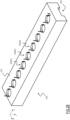
- Figure 1A it is schematically represented by means of an isometric view a short section of an article conveyor system, or simply conveyor of articles, 100 wherein solutions according to one or more embodiments of the present invention can be applied.
- Figure 1B is a top view (parallel to the x and y directions) of the section of the conveyor of articles 100 of Figure 1A .
- the conveyor of articles 100 is a conveyor of the chain type, comprising a transport chain 105 for transporting articles, such as for example beverage bottles (mineral water, soft drinks and the like), not shown in the figure.
- articles such as for example beverage bottles (mineral water, soft drinks and the like)
- the type of conveyor, and the nature of the articles it is intended to convey are not limiting for the purposes of the present invention, which generally applies to any type of conveyor, regardless of the nature of the articles to be conveyed.
- the transport chain 105 can be generally constituted by a plurality of chain chunks, each of which is in turn made up of a plurality of chain links 110, for example made of plastic material, hinged one to one another by means of pins.
- Each chain link 110 comprises a first substantially flat face 112 and a second face (not visible in Figures 1A and 1B ) opposite to the first face.
- the first faces 112 of the chain links 110 are adapted to define a support surface which is substantially flat (parallel to the x and y directions) and/or smooth for supporting the articles to be transported.
- Figures 1A and 1B show only a portion of the transport chain 105, for example corresponding to a single chain chunk.
- the complete transport chain 105 may instead be much longer, and also form a closed loop comprising a forward section, or so-called top run, in which the first faces 112 of the chain links 110 face upwards so as to define the support surface (as shown in Figures 1A and 1B ), and a return section, or so-called bottom run, (not visible in Figures 1A and 1B ) located in an underlying portion of the conveyor, wherein the first faces 112 of the chain links 110 face downwards.
- the transport chain 105 is slidingly supported by a guide structure 120.
- the guide structure has a substantially parallelepiped shape comprising an upper surface 125 and a smaller surface 127 parallel to the directions x, y.
- a guide groove 128 extending longitudinally along a direction parallel to the direction x is made in the upper surface 125 of the guide structure 120, which guide groove 128 defines lateral guide profiles 130 made of a low friction coefficient material on which the transport chain 105 slidingly rests.
- the conveyor of articles 100 comprises motor means, or so-called linear motor, for imparting movement to the transport chain 105 with respect to the guide structure 120.
- the transport chain 105 slides with respect to the guide structure 120 along a movement direction D defined by the guide groove 128.
- the movement direction D is therefore parallel to the x direction.
- the motor means include a linear electric motor comprising permanent magnets located in the chain links 110 of the transport chain 105 and electromagnets - called "propulsion electromagnets" - located in the guide structure 120.
- Figure 2A is a sectional view of the conveyor of articles 100 along a section plane perpendicular to the support surface and passing through the axis A - A of Figure 1B .
- Figure 2B is an isometric view of the guide structure 120 upside down, that is where the lower surface 127 is seen, and where the transport chain 105 has been removed.
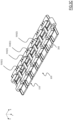
- Figure 2C is an isometric view of the transport chain 105 upside down - that is, in which the lower faces (identified with 202 ) of the chain links 110 opposite to the first faces 112 are visible.
- Figure 2D is an enlarged view of the portion of Figure 2A identified with the reference P1.
- each chain link 110 comprises a respective permanent magnet, or simply "magnet", configured to generate a constant magnetic field along a direction substantially perpendicular to the support surface, i.e., along the z direction.
- the magnets can be neodymium-based permanent magnets.
- the concepts of the present invention can also be applied to cases in which the magnets are formed with different materials, such as metallic materials or composite materials.
- the magnets define along the movement direction D of the chain a sequence of magnets comprising an alternation of first magnets 210(1) and second magnets 210(2).
- the first magnets 210(1) and the second magnets 210(2) have their magnetic north poles and magnetic south poles aligned along the z direction.
- Each of the first magnets 210(1) has the north pole N(1) which is closer to the first face 112 of the chain link 110 - and therefore to the support surface - with respect to the south pole S(1).
- Each of the second magnets 210(2) has the south pole S(2) which is closer to the first face 112 of the chain link 110 - and therefore to the support surface - with respect to the north pole N(2).
- the magnetic fields generated by the sequence of magnets 210(1), 210(2) provide for an alternation of magnetic fields B(1) - generated by magnets 210(1) - and magnetic fields B(2) - generated by magnets 210(2) - opposite to each other.
- the propulsion electromagnets are configured to be energized so as to generate a variable-intensity oscillating magnetic field along a direction substantially perpendicular to the support surface, that is parallel to the direction z.
- the propulsion electromagnets are located in the guide structure 120 and define along the movement direction D of the chain a sequence of propulsion electromagnets comprising an alternation of first propulsion electromagnets 230(1), second propulsion electromagnets 230(2) and third propulsion electromagnets 230(3) in which each first propulsion electromagnet 230(1) is followed by a second propulsion electromagnet 230(2) and each second propulsion electromagnet 230(2) is followed by a third propulsion electromagnet 230(3).
- each of the propulsion electromagnets 230(1), 230(2), 230(3) of the sequence comprises a coil 240 wound around a core 245 of ferritic or ferromagnetic material and having a main axis perpendicular to the support surface, that is parallel to the z direction.
- the propulsion electromagnets 230(1), 230(2), 230(3) are powered by a three-phase electric system which provides that each propulsion electromagnet 230(1) is powered by an alternating electric current having frequency f which has a difference of phase of 120° with respect to the alternating current having frequency f which supplies each propulsion electromagnet 230(2) and a difference of phase of 240° with respect to the alternating current having frequency f which supplies each propulsion electromagnet 230(3).
- the magnetic fields generated by the sequence of propulsion electromagnets 230(1), 230(2), 230(3) provide for an alternation of oscillating magnetic fields Bac(1) - generated by the propulsion electromagnets 230(1) -, Bac(2) - generated by the propulsion electromagnets 230(2) - and Bac(3) - generated by the propulsion electromagnets 230(3) - being reciprocally phase shifted by ⁇ 120°.
- Each chain link 110 is in fact subjected to a simultaneous push action - caused by the magnetic field generated by one or more propulsion electromagnets 230(1), 230(2), 230(3) positioned upstream of the chain link 110 - and traction action - caused by the magnetic field generated by one or more propulsion electromagnets 230(1), 230(2), 230(3) positioned downstream of the chain link 110.
- each propulsion electromagnet 230(1), 230(2), 230(3), the mutual distances between the magnets 210(1), 210(2), the distances between the propulsion electromagnets 230(1), 230(2), 230(3) and the magnets 210(1), 210(2), as well as the intensities of the oscillating magnetic fields Bac(1), Bac(2), Bac(3) and of the constant magnetic fields B(1), B(2) are properly selected so that the push and traction actions the chain links 100 are subjected to do not cause unwanted lifting (along the z direction) of the transport chain 105 with respect to the guide structure 120.
- the housing of the magnets 210(1), 210(2) in the chain links 110 is obtained by embedding ferromagnetic elements into the molten plastic material during the molding phase of the chain links 110 and then magnetizing these ferromagnetic elements at a later time.
- the magnets 210(1), 210(2) are encapsulated within the chain links 110 themselves, avoiding the formation of interstices and cracks within which dirt accumulation can occur.
- the magnets 210(1), 210(2) will be defended from the chemical aggression typical of working environments of particular applications.
- magnets 210(1), 210(2) are embedded within the chain links 110, for example inserted in appropriate niches made in the chain links 110 themselves. It will be possible to seal the niche housing the permanent magnet with suitable cold resin coating both to protect it from environmental agents and to ensure the stability of the coupling to the chain hinge.
- the chain conveyor of articles 100 just described allows the transport chain 105 to move on the guide structure 120 in a more fluid manner, since no toothed coupling is present. Moreover, the absence of toothed couplings and of high stresses on the hinges meshing on the traction pinions, results in a reduction in the wear the chain links 110 are subjected to, and makes the conveyor of articles 100 less prone to the production of dust, squeaking and breaking due to the reaching of fatigue limits of the plastic material.
- each chain link 110 comprises a respective magnet 210(1) or 210(2), similar considerations apply when the magnets 210(1), 210(2) are provided in some chain links 110 only, for example on alternate chain links 110.
- the concepts of the present invention can also be applied in the case in which the propulsion electromagnets 230(1), 230(2), 230(3) have a structure that is different from the described one, provided that they are capable of generating oscillating magnetic fields Bac(1), Bac(2), Bac(3) perpendicular to the support surface.
- the propulsion electromagnets have been described to be supplied by means of a three-phase electrical system, the concepts of the present invention can also be applied to the cases with power supplying through two-phase or single-phase electrical systems.
- the conveyor of articles 100 further comprises magnetic sensing means 250 for detecting the magnetic field B(1), B(2) generated by magnets 210(1), 210(2) during the operation of the conveyor of articles 100.
- the magnetic sensing means 250 comprise a Hall sensor located in the guide groove 128 so as to be hit by the magnetic fields B(1), B(2) generated by the magnets 210(1), 210(2) as the transport chain 105 slides over it.
- the transport chain is a chain that forms a closed loop, it is sufficient to provide a single Hall sensor (or equivalent sensor), while in the case of several separate chain chunks, in order to be able to monitor the position and the speed of each chunk, the presence of several Hall sensors (or equivalent sensors) distributed along the movement path may be required.
- the conveyor of articles 100 is provided with control means (not shown in the figures) adapted to control the intensity of the current flowing in the coils of the propulsion electromagnets 230(1), 230(2), 230(3) - and then adjusting the resulting magnetic force pushing the transport chain 105 - based on information on the effective operation of the conveyor of articles 100 obtained by the magnetic sensing means 250.
- a linear electric motor will now be described which can be used to move the transport chain 105 of the conveyor of articles 100 according to the present invention.
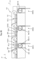
- Figure 3A is a sectional view of the conveyor of articles 100 along a section plane perpendicular to the support surface and passing through the axis A - A of Figure 1B .
- Figure 3B is an isometric view of the guide structure 120 upside down, i.e., where the bottom surface is visible 127, and where the transport chain 105 has been removed.
- Figure 3C is an isometric view of the transport chain 105 upside down - that is, where the lower faces 202 of the chain links 110 opposite to the first faces 112 are visible.
- Figure 3D is an enlarged view of the portion of Figure 3A identified with the reference P2.
- Figure 3E is a sectional view of the conveyor of articles 100 along a section plane parallel to the support surface and passing through the axis B- B of Figure 3A that passes through the chain links 110 of the transport chain 105 along a direction parallel to the direction x.
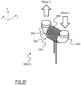
- Figure 3F is an isometric view of one of the propulsion electromagnets located in the guide structure 120.
- the magnets define along the movement direction D of the chain a sequence of magnets comprising an alternation of first magnets 310(1) and second magnets 310(2) in which each magnet 310(1), 310(2) is a permanent magnet in the shape of a "u" having the north and south magnetic poles that are aligned along the y direction.
- each magnet 310(1), 310(2) comprises a plate 320 made of iron, or of a low saturation ferritic material, wherein two neodymium-based magnetic elements 322, 324 are connected on the lower surface - i.e., the surface facing the guide structure 120 - of the plate 320.
- the concepts of the present invention can also be applied to cases in which the magnetic elements 322, 324 are made of different materials, such as metallic or composite materials.
- each first magnet 310(1) The mutual position along the y direction of the north and south magnetic poles of each first magnet 310(1) is opposite to that of the north and south magnetic poles of each second magnet 310(2).
- the magnetic fields generated by the sequence of magnets 310(1), 310(2) in a direction perpendicular to the support surface - that is, parallel to the z direction - provide for an alternation of magnetic fields B'(1) - generated by magnets 310(1) - and magnetic fields B'(2) - generated by magnets 210(2) - opposite to each other.
- the propelling electromagnets are configured to be energized so as to generate an oscillating magnetic field having variable intensity.
- the propulsion electromagnets are located in the guide structure 120 and define along the movement direction D of the chain a sequence of propulsion electromagnets comprising an alternation of first propulsion electromagnets 330(1), second propulsion electromagnets 330(2) and third propulsion electromagnets 330(3) in which each first propulsion electromagnet 330(1) is followed by a second propulsion electromagnet 330(2) and each second propulsion electromagnet 330(2) is followed by a third propulsion electromagnet 330(3).
- each of the propulsion electromagnets 330(1), 330(2), 330(3) of the sequence comprises:
- the propulsion electromagnets 330(1), 330(2), 330(3) are powered by means of a three-phase electrical system which provides that each propulsion electromagnet 330(1) is powered by an alternating electric current having frequency f which has a difference of phase of 120° with respect to the alternating current having frequency f which supplies each propulsion electromagnet 330(2) and a difference of phase of 240° with respect to the alternating current having frequency f which supplies each propulsion electromagnet 330(3).
- the magnetic fields generated by the sequence of propulsion electromagnets 330(1), 330(2), 330(3) provide for an alternation of oscillating magnetic fields Bac'(1) - generated by the propulsion electromagnets 330(1) -, Bac'(2) - generated by the propulsion electromagnets 330(2) - and Bac'(3) - generated by the propulsion electromagnets 330(3) - being reciprocally phase shifted by ⁇ 120°.
- each propulsion electromagnet 330(1), 330(2), 330(3) is then directed along a direction parallel to the z direction.
- FIG. 4A A short section of the conveyor of articles 400 is schematically represented in Figure 4A by an isometric view.
- Figure 4B is a top view (parallel to the x and y directions) of the section of the conveyor of articles 400 of Figure 4A .
- the conveyor of articles 400 as well is a chain-type conveyor, comprising a transport chain 405 for transporting articles , such as for example beverage bottles (mineral water, soft drinks and similar), not shown in the figure.
- articles such as for example beverage bottles (mineral water, soft drinks and similar)
- the type of conveyor, and the nature of the articles it is intended to carry are not limiting for the purposes of the present invention, which generally applies to any type of conveyor, regardless of the nature of the articles to be transported.
- the transport chain 405 can be constituted, in general, by a plurality of chain chunks, each of which is in turn constituted by a plurality of chain links 410, for example made of plastic material, hinged to each other by means of pins.
- Each chain link 410 comprises a substantially flat first face 412 and a second face opposite the first face.
- the transport chain 405 is slidably supported by a guide structure 420 having a guide groove 428 which longitudinally extends along a direction parallel to the x direction, and defines lateral guide profiles 430 made of a low friction coefficient material on which the transport chain 405 slidingly rests.
- the motor means for imparting movement to the transport chain 405 with respect to the guide structure 420 include a linear electric motor comprising permanent magnets located in the chain links 410 of the transport chain 405, and propulsion electromagnets located in the guide structure 420.
- Figure 4C is an isometric view of the transport chain 405 upside down - i.e., in which the lower faces 402 of the chain links 410 opposite to the first faces 412 are visible.
- Figure 4D is a sectional view of the conveyor of articles 400 along a section plane perpendicular to the support surface and passing through the A' - A' of Figure 4B .
- Figura 4E is a sectional view of the conveyor of articles 400 along a section plane parallel to the support surface and passing through the axis B' - B' of Figure 4D .
- Figure 4F is an enlarged view of the portion of Figure 4E identified with the reference P3.
- Figure 4G is a sectional view of the conveyor of articles along a section plane perpendicular to the support surface and passing through axis C'-C' of Figure 4E .
- Figure 4H is an isometric view of one of the propulsion electromagnets located in the guide structure 420.
- each chain link 410 of the transport chain 405 is provided with a pair of wall elements 440, 450 which protrude from below from the lower face 402 along a direction parallel to the z direction (and therefore perpendicular to the support surface).
- the wall elements 440, 450 extend along a direction parallel to the x direction, and are distant from each other by a distance S along the y direction.
- the wall elements 440, 450 of the various chain links 410 define as a whole an empty space 460 having a width equal to S which extends along the x direction.
- the groove 428 of the guide structure 420 has a width T along the y direction sufficiently wide to allow the wall elements 440, 450 to slide within the groove 428 without entering in contact with the inner walls of the latter perpendicular to the y direction when the transport chain 405 is supported by the guide structure 420.
- each chain link 410 comprises a pair of magnets comprising a first magnet 470(1) and a second magnet 470(2).
- the first magnet 470(1) is located in a respective wall element selected between the two wall elements 410, 420 of the chain link 410, while the second magnet 470(2) is located in the other wall element between the two wall elements 410, 420 of the chain link 410.
- the respective magnets 470(1), 470(2) are facing each other and are spaced apart - along the y direction - by a distance corresponding to the distance S.
- each wall element 410, 420 of a chain link 410 comprises a respective housing for accommodating one of the two magnets 470(1), 470(2) of the torque.
- the housing of the magnets 470(1), 470(2) in the wall elements 440, 450 of the chain links 410 can be obtained by embedding ferromagnetic elements in the molten plastic material during the molding step of the chain links 410 and then magnetising said ferromagnetic elements at a later time.
- the magnets 470(1), 470(2) generate a constant magnetic field along a direction parallel to the y direction.
- the magnets 470(1), 470(2) are arranged in their respective housings so as to have the north and south poles aligned along the y direction.
- the first magnet 470(1) has the north pole facing the second magnet 470(2)
- the second magnet 470(2) has the south pole facing the first magnet 470(1), so that the north pole of the first magnet 470(1) faces the south pole of the second magnet 470(2).
- the mutual position along y direction between the first magnet 470(1) and the second magnet 470(2) of a generic chain link 410 is opposite to that between the first magnet 470(1) and the second magnet 470(2) of the two adjacent chain links 410 in the transport chain 405.
- each first magnet 470(1) is alternately housed in the housing of the wall element 440 and in the housing of the wall element 450
- each second magnet 470(2) is housed alternately in the housing of the wall element 450 and in the housing of the wall element 440.
- the magnetic fields generated by the magnets 470(1) and 470(2) provide for an alternation of magnetic fields B(1)" - generated in the links 410 in which the magnets 470(1) are located in the wall elements 450 and the magnets 470(2) are located in the wall elements 440 - and magnetic fields B(2)" - generated in the links 410 in which the magnets 470(1) are located in the wall elements 440 and the magnets 470(2) are located in the wall elements 450 - opposite to each other.
- the propulsion electromagnets are configured to be energized so as to generate a variable intensity oscillating magnetic field along a direction parallel to the y direction, i.e., parallel to the magnetic fields B(1)" and B(2)" generated by the magnets 470(1) and 470(2).
- the propulsion electromagnets are located in the guide structure 420 and define, along the movement direction D of the chain, a sequence of propulsion electromagnets comprising an alternation of first propulsion electromagnets 480(1), second propulsion electromagnets 480(2) and third propulsion electromagnets 480(3) in which each first propulsion electromagnet 480(1) is followed by a second propulsion electromagnet 480(2) and each second propulsion electromagnet 480(2) is followed by a third propulsion electromagnet 480(3).
- the propulsion electromagnets 480(1), 480(2), 480(3) are located in the groove 428.
- the propulsion electromagnet 480(1), 480(2), 480(3) are housed in a support structure 482 which projects (along the z direction) from the bottom of the groove 428 and longitudinally extends along the groove 428 (parallel to the x direction).
- the support structure 482 has a width (along the direction y ) which is lower than the distance S between the wall elements 440 and 450 of the chain links 410 and is such to define with the side walls of the groove 428 two lateral channels 484, 486 having a width (along the y direction) greater than the thickness (along the y direction) of the wall elements 440 and 450. In this way, the wall elements 440 and 450 can slide within the side channels 484, 486 without touching the side walls when the transport chain 405 is slidably supported on the guide structure 420.
- each propulsion electromagnet 480(1), 480(2), 480(3) comprises a core 490 of ferritic or ferromagnetic material which extends within the structure support 482 along a direction parallel to the y direction, and d a coil 495 wound around the core 490, having an axis of symmetry which is also parallel to the y direction.
- the propulsion electromagnets 480(1), 480(2), 480(3) are localized between pairs of magnets 470(1), 470(2) facing to each other and having surfaces substantially perpendicular to the symmetry axis of the coil 495.
- the support structure 482 is made of thermoplastic materials, such as thermoplastic resins, and the cores 490 with the coils 495 are embedded in the thermoplastic material which forms the support structure 482.
- the propulsion electromagnets 480(1), 480(2), 480(3) are supplied by a three-phase electric system which provides for each propulsion electromagnet 480(1) to be powered by an alternating electric current having frequency f which has a difference of phase of 120° with respect to the alternating current having frequency f which supplies each propulsion electromagnet 480(2) and a difference of phase of 240° with respect to the alternating current having frequency f which supplies each propulsion electromagnet 480(3).
- the magnetic fields generated by the sequence propulsion electromagnets 480(1), 480(2), 480(3) provide an alternation of magnetic oscillating fields Bac"(1) - generated by the propulsion electromagnets 480(1) -, Bac"(2) - generated by the propulsion electromagnets 480(2) - and Bac"(3) - generated by the propulsion electromagnets 480(3) - being reciprocally phase shifted by ⁇ 120°.
- the oscillating magnetic fields Bac"(1), Bac”(2), Bac”(3) are directed along the y direction, i.e., parallel to the direction of the constant magnetic fields B(1)" and B(2)" generated by the magnets 470(1) and 470(2) accommodated in the wall elements 440, 450 of the mesh of the chain 410.
- the propulsion electromagnets 480(1), 480(2), 480(3) are surrounded (along the y direction) by pairs of magnets 470(1), 470(2) facing to each other, the magnetic coupling between the propulsion electromagnets 480(1), 480(2), 480(3) and the magnets 470(1), 470(2) is particularly effective, and the magnetic losses are reduced to a minimum. Since the magnetic coupling of propulsion electromagnets / magnets is particularly effective, in accordance with another embodiment of the present invention, the propulsion electromagnets 480(1), 480(2), 480(3) can be implemented by directly embedding the coils. 495 into the thermoplastic material which forms the support structure 482, without providing for the cores 490.
- each chain link 410 instead of containing a single pair of magnets 470(1), 470(2), may contain two or more pairs of magnets having the north poles and south poles aligned along the y direction, so as to generate more constant magnetic fields parallel to the y direction for each chain link 410.
- each chain link 410 may contain three pairs of magnets, with the wall element 450 comprising a first set of magnets consisting of a sequence (along the x direction) of three magnets 510(1), 510(2), 510(3), and the wall element 440 which comprises a second set of magnets consisting of a sequence (along the x direction) of additional three magnets 520(1), 520(2), 520(3).
- the magnet 510(1) is facing the magnet 520(1)
- the magnet 510(2) is facing the magnet 520(2)
- the magnet 510(3) is facing the magnet 520(3).
- Magnets facing to each other on opposing wall elements, as well as adjacent magnets in the same wall element have the north poles and the south poles arranged in opposite way. For example, in the exemplary embodiment shown in Figure 5 :
Landscapes
- Engineering & Computer Science (AREA)
- Power Engineering (AREA)
- Mechanical Engineering (AREA)
- Combustion & Propulsion (AREA)
- Physics & Mathematics (AREA)
- Chemical & Material Sciences (AREA)
- Microelectronics & Electronic Packaging (AREA)
- Electromagnetism (AREA)
- Non-Mechanical Conveyors (AREA)
- Linear Motors (AREA)
- Transition And Organic Metals Composition Catalysts For Addition Polymerization (AREA)
- Gloves (AREA)
- Control And Other Processes For Unpacking Of Materials (AREA)
Claims (12)
- Fördersystem (100), umfassend:- wenigstens eine Transportkette (105) umfassend eine Folge miteinander verbundener Kettenglieder- eine Führungsstruktur (120) zum gleitenden Abstützen der wenigstens einen Transportkette, so dass Kettenglieder der wenigstens einen Transportkette eine im Wesentlichen flache Auflagefläche zum Abstützen der zu transportierenden Gegenstände definieren, und- einen Motor, der bewirkt, dass sich die wenigstens eine Transportkette in Bezug auf die Führungsstruktur entlang einer ersten Richtung parallel zu der Auflagefläche bewegt, wobei:- der Motor einen elektrischen Linearmotor umfasst, der umfasst:- mehrere Magnete (210(1), 210(2); 310(1), 310(2)), die sich jeweils in einem entsprechenden Kettenglied befinden, und- eine Vielzahl von an der Führungsstruktur befindlichen Antriebselektromagneten (230(1), 230(2); 230(3), 330(1), 330(2), 330(3)), dadurch gekennzeichnet, dass:- jeder Magnet (210(1), 210(2); 310(1), 310(2)) so eingerichtet ist, dass er ein konstantes Magnetfeld entlang einer zweiten Richtung senkrecht zur ersten Richtung erzeugt;- jeder Antriebselektromagnet (230(1), 230 (2), 230(3); 330(1), 330(2), 330(3)) so eingerichtet ist, dass er derart erregt wird, dass er ein variables Magnetfeld entlang der zweiten Richtung derart erzeugt, dass er eine Magnetkraft entlang der ersten Richtung erzeugt, um die Bewegung entlang der ersten Richtung der wenigstens einen Transportkette in Bezug auf die Führungsstruktur zu bewirken, wobei:- mehrere Magnete (310(1), 310(2) ) eine Abfolge von Magneten definieren, die einen Wechsel von ersten Magneten (310(1) ) und zweiten Magneten (310(2) ) aufweisen;- jeder erste Magnet (310(1)) und jeder zweite Magnet (310(2) ) ein u-förmiger Magnet ist, bei dem der Nordpol und der Südpol entlang einer dritten Richtung senkrecht zu der ersten und der zweiten Richtung ausgerichtet sind, und- die gegenseitige Position entlang der dritten Richtung des Nordpols und der Südpol jedes ersten Magneten entgegengesetzt der gegenseitigen Position entlang der dritten Richtung des Nordpols und des Südpols jedes zweiten Magneten ist.
- Fördersystem (100) nach Anspruch 1, wobei die mehreren Antriebselektromagnete ( 230(1), 230(2), 230(3); 330(1), 330(2), 330(3) eine Sequenz von Antriebselektromagneten ( 230(1), 230(2) 230(3); 330(1), 330(2), 330(3)) entlang der ersten Richtung umfassen.
- Fördersystem (100) nach Anspruch 1 oder 2, bei dem die zweite Richtung rechtwinklig zur Auflagefläche verläuft.
- Fördersystem (100) nach Anspruch 3, wobei:- mehrere Magnete (210(1), 210(2)) eine Abfolge von Magneten definieren, die einen Wechsel der ersten Magneten (210(1)) und zweiten Magneten (210(2)) aufweisen;- jeder erste Magnet (210(1)) und jeder zweite Magnet (210(2)) den Nordpol und den Südpol davon aufweist, die entlang der zweiten Richtung ausgerichtet sind;- jeder erste Magnet ( 210(1)) den Nordpol davon aufweist, der näher an der Auflagefläche liegt als der Südpol davon, und- jeder zweite Magnet ( 210(2)) den Südpol davon aufweist, der näher an der Auflagefläche liegt als der Nordpol davon.
- Fördersystem (100) nach Anspruch 4, wobei jeder Antriebselektromagnet (230(1), 230(2), 230(3)) eine Spule mit der Symmetrieachse davon aufweist, die entlang der zweiten Richtung verläuft.
- Fördersystem (100) nach Anspruch 1, wobei jeder Antriebselektromagnet (330(1), 330(2), 330(3)) eine Spule (360) und ein jeweiliges u-förmiges ferritisches oder ferromagnetisches Element (340) aufweist, das einen ersten und einen zweiten Arm (342, 344) aufweist, die sich entlang der zweiten Richtung erstrecken, und einen Verbindungsabschnitt (346), der den ersten und den zweiten Arm verbindet und sich entlang der dritten Richtung erstreckt, wobei jede Spule auf den Verbindungsabschnitt des jeweiligen u-förmigen Elements aufgewickelt wird.
- Fördersystem (100) eines der vorhergehenden Ansprüche, wobei jeder Magnet ein Neodym-basierter Permanentmagnet ist.
- Fördersystem (100) eines der vorhergehenden Ansprüche, wobei jeder Magnet in dem jeweiligen Kettenglied vergraben ist.
- Fördersystem (100) eines der vorhergehenden Ansprüche umfasst ferner ein elektrisches Versorgungssystem zum Bestromen der Antriebselektromagnete, wobei das Stromversorgungssystem ein ausgewähltes ist von:- einem dreiphasigen Versorgungssystem;- einem zweiphasigen Versorgungssystem und- einem einphasigen Versorgungssystem.
- Fördersystem (100) nach Anspruch 9, das ferner umfasst:- Mittel (250) zur Erfassung des von den Magneten erzeugten Magnetfelds und- Mittel zur Beurteilung der Position und/oder der Bewegungsgeschwindigkeit der wenigstens einen Transportkette basierend auf dem erfassten Magnetfeld.
- Fördersystem (100) eines der vorhergehenden Ansprüche, wobei die wenigstens eine Transportkette eine geschlossene Transportkette aufweist.
- Fördersystem (100) nach einem der Ansprüche 1 bis 10, wobei jeder der wenigstens einen Transportkette ein von den anderen Teilstücken getrennter Teil der Transportkette ist.
Applications Claiming Priority (2)
| Application Number | Priority Date | Filing Date | Title |
|---|---|---|---|
| IT201800001907A IT201800001907A1 (it) | 2018-01-25 | 2018-01-25 | Trasportatore di articoli |
| PCT/EP2019/051723 WO2019145406A1 (en) | 2018-01-25 | 2019-01-24 | Conveyor of articles |
Publications (2)
| Publication Number | Publication Date |
|---|---|
| EP3743363A1 EP3743363A1 (de) | 2020-12-02 |
| EP3743363B1 true EP3743363B1 (de) | 2024-01-31 |
Family
ID=62044860
Family Applications (1)
| Application Number | Title | Priority Date | Filing Date |
|---|---|---|---|
| EP19701517.5A Active EP3743363B1 (de) | 2018-01-25 | 2019-01-24 | Artikelförderer |
Country Status (5)
| Country | Link |
|---|---|
| US (1) | US11305943B2 (de) |
| EP (1) | EP3743363B1 (de) |
| CN (1) | CN111655599B (de) |
| IT (1) | IT201800001907A1 (de) |
| WO (1) | WO2019145406A1 (de) |
Families Citing this family (3)
| Publication number | Priority date | Publication date | Assignee | Title |
|---|---|---|---|---|
| AT523565A1 (de) * | 2020-03-05 | 2021-09-15 | B & R Ind Automation Gmbh | Transporteinrichtung |
| US11645482B2 (en) | 2020-08-26 | 2023-05-09 | Cattron North America, Inc. | Radio-frequency identification (RFID) systems and methods for changing operator control unit (OCU) configurations |
| CN117326265A (zh) * | 2023-11-20 | 2024-01-02 | 广州市豪田机械设备有限公司 | 一种用于封边机输送机构的链块 |
Family Cites Families (11)
| Publication number | Priority date | Publication date | Assignee | Title |
|---|---|---|---|---|
| IT1215730B (it) * | 1988-01-19 | 1990-02-22 | Regina Sud Spa | Trasportatore a catena perfezionato. |
| IT237914Y1 (it) * | 1997-09-18 | 2000-09-29 | Regina Sud Spa | Guida magnetica migliorata |
| ITTV20040115A1 (it) * | 2004-10-18 | 2005-01-18 | Plastomeccanica Spa | Guida, particolarmente per nastri trasportatori. |
| DE102005019036A1 (de) * | 2005-04-23 | 2006-10-26 | Ima Klessmann Gmbh Holzbearbeitungssysteme | Werkstücktransportvorrichtung mit zumindest einer endlos umlaufenden Kette |
| ATE446930T1 (de) * | 2006-07-12 | 2009-11-15 | Homag Holzbearbeitungssysteme | Kettenglied für eine umlaufende transportkette einer werkzeugmaschine, sowie doppelendprofiler mit aus solchen kettengliedern gebildeten führungsketten |
| DE102006036328A1 (de) * | 2006-08-03 | 2008-02-07 | Siemens Ag | Umlaufeinrichtung für eine Transportkette oder ein Transportband |
| WO2010108509A1 (de) * | 2009-03-25 | 2010-09-30 | Trumpf Werkzeugmaschinen Gmbh + Co. Kg | Elektrischer linearantrieb |
| ITMI20120120A1 (it) * | 2012-01-31 | 2013-08-01 | Rexnord Marbett Srl | Sistema di monitoraggio per la misurazione della velocita¿ e dell¿allungamento di catene di trasporto di trasportatori di articoli |
| WO2016131879A1 (en) * | 2015-02-18 | 2016-08-25 | Rexnord Flattop Europe S.R.L. | Guide for chain for articles conveyor |
| CN105151803B (zh) * | 2015-09-24 | 2018-03-27 | Abb瑞士股份有限公司 | 输送装置及其传输系统 |
| CN105391269A (zh) | 2015-12-16 | 2016-03-09 | 优丫优科技股份有限公司 | 一种新型的永磁直线步进电机 |
-
2018
- 2018-01-25 IT IT201800001907A patent/IT201800001907A1/it unknown
-
2019
- 2019-01-24 EP EP19701517.5A patent/EP3743363B1/de active Active
- 2019-01-24 WO PCT/EP2019/051723 patent/WO2019145406A1/en not_active Ceased
- 2019-01-24 US US16/964,326 patent/US11305943B2/en active Active
- 2019-01-24 CN CN201980010116.4A patent/CN111655599B/zh active Active
Non-Patent Citations (1)
| Title |
|---|
| TECNOTION B.V.: "How does a linear motor work?", YOUTUBE, 22 May 2017 (2017-05-22), pages 1 pp., XP054981985, Retrieved from the Internet <URL:https://www.youtube.com/watch?v=0_QBl6-_jJU&t=105s> [retrieved on 20210629] * |
Also Published As
| Publication number | Publication date |
|---|---|
| IT201800001907A1 (it) | 2019-07-25 |
| CN111655599B (zh) | 2023-05-23 |
| CN111655599A (zh) | 2020-09-11 |
| US20210039891A1 (en) | 2021-02-11 |
| EP3743363A1 (de) | 2020-12-02 |
| WO2019145406A1 (en) | 2019-08-01 |
| US11305943B2 (en) | 2022-04-19 |
Similar Documents
| Publication | Publication Date | Title |
|---|---|---|
| US8511460B2 (en) | Conveyor belt apparatus including magnetically actuated rollers | |
| EP3743363B1 (de) | Artikelförderer | |
| JP6340407B2 (ja) | 磁気的に駆動される移動子を有する転換コンベヤ | |
| CN104271476B (zh) | 具有通过电磁感应致动的辊的输送机 | |
| JP6506894B2 (ja) | 線状物品誘導装置 | |
| US7597190B2 (en) | Belt including a flexible rare earth magnetic strip and conveyor utilizing a belt including a flexible rare earth magnetic strip | |
| CN105531423A (zh) | 件货用的由线性马达操作的传输系统的无源切换装置 | |
| JPS6115557A (ja) | 浮上式搬送装置 | |
| JP2012516130A (ja) | 短ブロックのリニア同期モータおよび切り替え機構によって動力供給される改良された輸送システム | |
| US7121400B2 (en) | Systems and methods for guiding conveyance elements | |
| CN112499140A (zh) | 分拣小车、磁力齿条及分拣机 | |
| CA2458522C (en) | Induction drive for induction driven conveyor | |
| JP2630558B2 (ja) | 仕分けコンベヤの切換装置 | |
| KR100840927B1 (ko) | 선형전동기 및 비접촉 급전시스템을 이용한 철도차량시스템 | |
| US20070170043A1 (en) | Conveyor for material with magnetically driven flights in a tube | |
| JP4165117B2 (ja) | 真空容器内搬送装置 | |
| JP2008166842A (ja) | 真空容器内搬送装置 | |
| KR102251764B1 (ko) | 자기부상 반송장치 | |
| JPS63133803A (ja) | 磁気浮上搬送装置 | |
| JP2006044936A (ja) | リニアモータ駆動チェーン | |
| JP4788993B2 (ja) | ワーク搬送機構に用いられる吸引防止装置及びその吸引防止方法 | |
| JP4935724B2 (ja) | 搬送設備 | |
| JPS62155702A (ja) | 移送装置 | |
| JP2005306551A (ja) | 物品仕分けコンベヤ装置 | |
| JPH01264740A (ja) | 切粉搬送装置 |
Legal Events
| Date | Code | Title | Description |
|---|---|---|---|
| STAA | Information on the status of an ep patent application or granted ep patent |
Free format text: STATUS: UNKNOWN |
|
| STAA | Information on the status of an ep patent application or granted ep patent |
Free format text: STATUS: THE INTERNATIONAL PUBLICATION HAS BEEN MADE |
|
| PUAI | Public reference made under article 153(3) epc to a published international application that has entered the european phase |
Free format text: ORIGINAL CODE: 0009012 |
|
| STAA | Information on the status of an ep patent application or granted ep patent |
Free format text: STATUS: REQUEST FOR EXAMINATION WAS MADE |
|
| 17P | Request for examination filed |
Effective date: 20200811 |
|
| AK | Designated contracting states |
Kind code of ref document: A1 Designated state(s): AL AT BE BG CH CY CZ DE DK EE ES FI FR GB GR HR HU IE IS IT LI LT LU LV MC MK MT NL NO PL PT RO RS SE SI SK SM TR |
|
| AX | Request for extension of the european patent |
Extension state: BA ME |
|
| DAV | Request for validation of the european patent (deleted) | ||
| DAX | Request for extension of the european patent (deleted) | ||
| STAA | Information on the status of an ep patent application or granted ep patent |
Free format text: STATUS: EXAMINATION IS IN PROGRESS |
|
| 17Q | First examination report despatched |
Effective date: 20210705 |
|
| GRAP | Despatch of communication of intention to grant a patent |
Free format text: ORIGINAL CODE: EPIDOSNIGR1 |
|
| STAA | Information on the status of an ep patent application or granted ep patent |
Free format text: STATUS: GRANT OF PATENT IS INTENDED |
|
| INTG | Intention to grant announced |
Effective date: 20230323 |
|
| P01 | Opt-out of the competence of the unified patent court (upc) registered |
Effective date: 20230522 |
|
| GRAJ | Information related to disapproval of communication of intention to grant by the applicant or resumption of examination proceedings by the epo deleted |
Free format text: ORIGINAL CODE: EPIDOSDIGR1 |
|
| STAA | Information on the status of an ep patent application or granted ep patent |
Free format text: STATUS: EXAMINATION IS IN PROGRESS |
|
| GRAP | Despatch of communication of intention to grant a patent |
Free format text: ORIGINAL CODE: EPIDOSNIGR1 |
|
| STAA | Information on the status of an ep patent application or granted ep patent |
Free format text: STATUS: GRANT OF PATENT IS INTENDED |
|
| INTC | Intention to grant announced (deleted) | ||
| INTG | Intention to grant announced |
Effective date: 20230822 |
|
| GRAS | Grant fee paid |
Free format text: ORIGINAL CODE: EPIDOSNIGR3 |
|
| GRAA | (expected) grant |
Free format text: ORIGINAL CODE: 0009210 |
|
| STAA | Information on the status of an ep patent application or granted ep patent |
Free format text: STATUS: THE PATENT HAS BEEN GRANTED |
|
| AK | Designated contracting states |
Kind code of ref document: B1 Designated state(s): AL AT BE BG CH CY CZ DE DK EE ES FI FR GB GR HR HU IE IS IT LI LT LU LV MC MK MT NL NO PL PT RO RS SE SI SK SM TR |
|
| REG | Reference to a national code |
Ref country code: GB Ref legal event code: FG4D Ref country code: CH Ref legal event code: EP |
|
| REG | Reference to a national code |
Ref country code: IE Ref legal event code: FG4D |
|
| REG | Reference to a national code |
Ref country code: DE Ref legal event code: R096 Ref document number: 602019045918 Country of ref document: DE |
|
| REG | Reference to a national code |
Ref country code: NL Ref legal event code: FP |
|
| REG | Reference to a national code |
Ref country code: LT Ref legal event code: MG9D |
|
| PG25 | Lapsed in a contracting state [announced via postgrant information from national office to epo] |
Ref country code: IS Free format text: LAPSE BECAUSE OF FAILURE TO SUBMIT A TRANSLATION OF THE DESCRIPTION OR TO PAY THE FEE WITHIN THE PRESCRIBED TIME-LIMIT Effective date: 20240531 |
|
| PG25 | Lapsed in a contracting state [announced via postgrant information from national office to epo] |
Ref country code: LT Free format text: LAPSE BECAUSE OF FAILURE TO SUBMIT A TRANSLATION OF THE DESCRIPTION OR TO PAY THE FEE WITHIN THE PRESCRIBED TIME-LIMIT Effective date: 20240131 |
|
| PG25 | Lapsed in a contracting state [announced via postgrant information from national office to epo] |
Ref country code: GR Free format text: LAPSE BECAUSE OF FAILURE TO SUBMIT A TRANSLATION OF THE DESCRIPTION OR TO PAY THE FEE WITHIN THE PRESCRIBED TIME-LIMIT Effective date: 20240501 |
|
| REG | Reference to a national code |
Ref country code: AT Ref legal event code: MK05 Ref document number: 1653753 Country of ref document: AT Kind code of ref document: T Effective date: 20240131 |
|
| PG25 | Lapsed in a contracting state [announced via postgrant information from national office to epo] |
Ref country code: HR Free format text: LAPSE BECAUSE OF FAILURE TO SUBMIT A TRANSLATION OF THE DESCRIPTION OR TO PAY THE FEE WITHIN THE PRESCRIBED TIME-LIMIT Effective date: 20240131 Ref country code: RS Free format text: LAPSE BECAUSE OF FAILURE TO SUBMIT A TRANSLATION OF THE DESCRIPTION OR TO PAY THE FEE WITHIN THE PRESCRIBED TIME-LIMIT Effective date: 20240430 |
|
| PG25 | Lapsed in a contracting state [announced via postgrant information from national office to epo] |
Ref country code: ES Free format text: LAPSE BECAUSE OF FAILURE TO SUBMIT A TRANSLATION OF THE DESCRIPTION OR TO PAY THE FEE WITHIN THE PRESCRIBED TIME-LIMIT Effective date: 20240131 |
|
| PG25 | Lapsed in a contracting state [announced via postgrant information from national office to epo] |
Ref country code: AT Free format text: LAPSE BECAUSE OF FAILURE TO SUBMIT A TRANSLATION OF THE DESCRIPTION OR TO PAY THE FEE WITHIN THE PRESCRIBED TIME-LIMIT Effective date: 20240131 |
|
| PG25 | Lapsed in a contracting state [announced via postgrant information from national office to epo] |
Ref country code: RS Free format text: LAPSE BECAUSE OF FAILURE TO SUBMIT A TRANSLATION OF THE DESCRIPTION OR TO PAY THE FEE WITHIN THE PRESCRIBED TIME-LIMIT Effective date: 20240430 Ref country code: NO Free format text: LAPSE BECAUSE OF FAILURE TO SUBMIT A TRANSLATION OF THE DESCRIPTION OR TO PAY THE FEE WITHIN THE PRESCRIBED TIME-LIMIT Effective date: 20240430 Ref country code: LT Free format text: LAPSE BECAUSE OF FAILURE TO SUBMIT A TRANSLATION OF THE DESCRIPTION OR TO PAY THE FEE WITHIN THE PRESCRIBED TIME-LIMIT Effective date: 20240131 Ref country code: IS Free format text: LAPSE BECAUSE OF FAILURE TO SUBMIT A TRANSLATION OF THE DESCRIPTION OR TO PAY THE FEE WITHIN THE PRESCRIBED TIME-LIMIT Effective date: 20240531 Ref country code: HR Free format text: LAPSE BECAUSE OF FAILURE TO SUBMIT A TRANSLATION OF THE DESCRIPTION OR TO PAY THE FEE WITHIN THE PRESCRIBED TIME-LIMIT Effective date: 20240131 Ref country code: GR Free format text: LAPSE BECAUSE OF FAILURE TO SUBMIT A TRANSLATION OF THE DESCRIPTION OR TO PAY THE FEE WITHIN THE PRESCRIBED TIME-LIMIT Effective date: 20240501 Ref country code: FI Free format text: LAPSE BECAUSE OF FAILURE TO SUBMIT A TRANSLATION OF THE DESCRIPTION OR TO PAY THE FEE WITHIN THE PRESCRIBED TIME-LIMIT Effective date: 20240131 Ref country code: ES Free format text: LAPSE BECAUSE OF FAILURE TO SUBMIT A TRANSLATION OF THE DESCRIPTION OR TO PAY THE FEE WITHIN THE PRESCRIBED TIME-LIMIT Effective date: 20240131 Ref country code: BG Free format text: LAPSE BECAUSE OF FAILURE TO SUBMIT A TRANSLATION OF THE DESCRIPTION OR TO PAY THE FEE WITHIN THE PRESCRIBED TIME-LIMIT Effective date: 20240131 Ref country code: AT Free format text: LAPSE BECAUSE OF FAILURE TO SUBMIT A TRANSLATION OF THE DESCRIPTION OR TO PAY THE FEE WITHIN THE PRESCRIBED TIME-LIMIT Effective date: 20240131 |
|
| PG25 | Lapsed in a contracting state [announced via postgrant information from national office to epo] |
Ref country code: PL Free format text: LAPSE BECAUSE OF FAILURE TO SUBMIT A TRANSLATION OF THE DESCRIPTION OR TO PAY THE FEE WITHIN THE PRESCRIBED TIME-LIMIT Effective date: 20240131 Ref country code: PT Free format text: LAPSE BECAUSE OF FAILURE TO SUBMIT A TRANSLATION OF THE DESCRIPTION OR TO PAY THE FEE WITHIN THE PRESCRIBED TIME-LIMIT Effective date: 20240531 |
|
| PG25 | Lapsed in a contracting state [announced via postgrant information from national office to epo] |
Ref country code: SE Free format text: LAPSE BECAUSE OF FAILURE TO SUBMIT A TRANSLATION OF THE DESCRIPTION OR TO PAY THE FEE WITHIN THE PRESCRIBED TIME-LIMIT Effective date: 20240131 Ref country code: PT Free format text: LAPSE BECAUSE OF FAILURE TO SUBMIT A TRANSLATION OF THE DESCRIPTION OR TO PAY THE FEE WITHIN THE PRESCRIBED TIME-LIMIT Effective date: 20240531 Ref country code: PL Free format text: LAPSE BECAUSE OF FAILURE TO SUBMIT A TRANSLATION OF THE DESCRIPTION OR TO PAY THE FEE WITHIN THE PRESCRIBED TIME-LIMIT Effective date: 20240131 Ref country code: LV Free format text: LAPSE BECAUSE OF FAILURE TO SUBMIT A TRANSLATION OF THE DESCRIPTION OR TO PAY THE FEE WITHIN THE PRESCRIBED TIME-LIMIT Effective date: 20240131 |
|
| PG25 | Lapsed in a contracting state [announced via postgrant information from national office to epo] |
Ref country code: DK Free format text: LAPSE BECAUSE OF FAILURE TO SUBMIT A TRANSLATION OF THE DESCRIPTION OR TO PAY THE FEE WITHIN THE PRESCRIBED TIME-LIMIT Effective date: 20240131 |
|
| PG25 | Lapsed in a contracting state [announced via postgrant information from national office to epo] |
Ref country code: SM Free format text: LAPSE BECAUSE OF FAILURE TO SUBMIT A TRANSLATION OF THE DESCRIPTION OR TO PAY THE FEE WITHIN THE PRESCRIBED TIME-LIMIT Effective date: 20240131 |
|
| PG25 | Lapsed in a contracting state [announced via postgrant information from national office to epo] |
Ref country code: EE Free format text: LAPSE BECAUSE OF FAILURE TO SUBMIT A TRANSLATION OF THE DESCRIPTION OR TO PAY THE FEE WITHIN THE PRESCRIBED TIME-LIMIT Effective date: 20240131 Ref country code: CZ Free format text: LAPSE BECAUSE OF FAILURE TO SUBMIT A TRANSLATION OF THE DESCRIPTION OR TO PAY THE FEE WITHIN THE PRESCRIBED TIME-LIMIT Effective date: 20240131 |
|
| PG25 | Lapsed in a contracting state [announced via postgrant information from national office to epo] |
Ref country code: SK Free format text: LAPSE BECAUSE OF FAILURE TO SUBMIT A TRANSLATION OF THE DESCRIPTION OR TO PAY THE FEE WITHIN THE PRESCRIBED TIME-LIMIT Effective date: 20240131 |
|
| PG25 | Lapsed in a contracting state [announced via postgrant information from national office to epo] |
Ref country code: SM Free format text: LAPSE BECAUSE OF FAILURE TO SUBMIT A TRANSLATION OF THE DESCRIPTION OR TO PAY THE FEE WITHIN THE PRESCRIBED TIME-LIMIT Effective date: 20240131 Ref country code: SK Free format text: LAPSE BECAUSE OF FAILURE TO SUBMIT A TRANSLATION OF THE DESCRIPTION OR TO PAY THE FEE WITHIN THE PRESCRIBED TIME-LIMIT Effective date: 20240131 Ref country code: RO Free format text: LAPSE BECAUSE OF FAILURE TO SUBMIT A TRANSLATION OF THE DESCRIPTION OR TO PAY THE FEE WITHIN THE PRESCRIBED TIME-LIMIT Effective date: 20240131 Ref country code: EE Free format text: LAPSE BECAUSE OF FAILURE TO SUBMIT A TRANSLATION OF THE DESCRIPTION OR TO PAY THE FEE WITHIN THE PRESCRIBED TIME-LIMIT Effective date: 20240131 Ref country code: DK Free format text: LAPSE BECAUSE OF FAILURE TO SUBMIT A TRANSLATION OF THE DESCRIPTION OR TO PAY THE FEE WITHIN THE PRESCRIBED TIME-LIMIT Effective date: 20240131 Ref country code: CZ Free format text: LAPSE BECAUSE OF FAILURE TO SUBMIT A TRANSLATION OF THE DESCRIPTION OR TO PAY THE FEE WITHIN THE PRESCRIBED TIME-LIMIT Effective date: 20240131 |
|
| REG | Reference to a national code |
Ref country code: DE Ref legal event code: R097 Ref document number: 602019045918 Country of ref document: DE |
|
| PLBE | No opposition filed within time limit |
Free format text: ORIGINAL CODE: 0009261 |
|
| STAA | Information on the status of an ep patent application or granted ep patent |
Free format text: STATUS: NO OPPOSITION FILED WITHIN TIME LIMIT |
|
| 26N | No opposition filed |
Effective date: 20241101 |
|
| PG25 | Lapsed in a contracting state [announced via postgrant information from national office to epo] |
Ref country code: SI Free format text: LAPSE BECAUSE OF FAILURE TO SUBMIT A TRANSLATION OF THE DESCRIPTION OR TO PAY THE FEE WITHIN THE PRESCRIBED TIME-LIMIT Effective date: 20240131 |
|
| REG | Reference to a national code |
Ref country code: CH Ref legal event code: PL |
|
| PG25 | Lapsed in a contracting state [announced via postgrant information from national office to epo] |
Ref country code: LU Free format text: LAPSE BECAUSE OF NON-PAYMENT OF DUE FEES Effective date: 20250124 Ref country code: MC Free format text: LAPSE BECAUSE OF FAILURE TO SUBMIT A TRANSLATION OF THE DESCRIPTION OR TO PAY THE FEE WITHIN THE PRESCRIBED TIME-LIMIT Effective date: 20240131 |
|
| GBPC | Gb: european patent ceased through non-payment of renewal fee |
Effective date: 20250124 |
|
| PG25 | Lapsed in a contracting state [announced via postgrant information from national office to epo] |
Ref country code: GB Free format text: LAPSE BECAUSE OF NON-PAYMENT OF DUE FEES Effective date: 20250124 Ref country code: BE Free format text: LAPSE BECAUSE OF NON-PAYMENT OF DUE FEES Effective date: 20250131 |
|
| PG25 | Lapsed in a contracting state [announced via postgrant information from national office to epo] |
Ref country code: FR Free format text: LAPSE BECAUSE OF NON-PAYMENT OF DUE FEES Effective date: 20250131 |
|
| PG25 | Lapsed in a contracting state [announced via postgrant information from national office to epo] |
Ref country code: CH Free format text: LAPSE BECAUSE OF NON-PAYMENT OF DUE FEES Effective date: 20250131 |
|
| REG | Reference to a national code |
Ref country code: BE Ref legal event code: MM Effective date: 20250131 |
|
| PG25 | Lapsed in a contracting state [announced via postgrant information from national office to epo] |
Ref country code: IE Free format text: LAPSE BECAUSE OF NON-PAYMENT OF DUE FEES Effective date: 20250124 |
|
| PGFP | Annual fee paid to national office [announced via postgrant information from national office to epo] |
Ref country code: NL Payment date: 20260121 Year of fee payment: 8 |
|
| PGFP | Annual fee paid to national office [announced via postgrant information from national office to epo] |
Ref country code: DE Payment date: 20260121 Year of fee payment: 8 |
|
| PGFP | Annual fee paid to national office [announced via postgrant information from national office to epo] |
Ref country code: IT Payment date: 20260126 Year of fee payment: 8 |