EP3737817B1 - Motorisiertes antriebssystem, verwendung des antriebssystems zur betätigung einer tür, herstellungsverfahren für ein antriebssystem - Google Patents
Motorisiertes antriebssystem, verwendung des antriebssystems zur betätigung einer tür, herstellungsverfahren für ein antriebssystem Download PDFInfo
- Publication number
- EP3737817B1 EP3737817B1 EP19700686.9A EP19700686A EP3737817B1 EP 3737817 B1 EP3737817 B1 EP 3737817B1 EP 19700686 A EP19700686 A EP 19700686A EP 3737817 B1 EP3737817 B1 EP 3737817B1
- Authority
- EP
- European Patent Office
- Prior art keywords
- drive
- assembly
- shaft
- brake
- rotor
- Prior art date
- Legal status (The legal status is an assumption and is not a legal conclusion. Google has not performed a legal analysis and makes no representation as to the accuracy of the status listed.)
- Active
Links
Images


Classifications
-
- E—FIXED CONSTRUCTIONS
- E05—LOCKS; KEYS; WINDOW OR DOOR FITTINGS; SAFES
- E05F—DEVICES FOR MOVING WINGS INTO OPEN OR CLOSED POSITION; CHECKS FOR WINGS; WING FITTINGS NOT OTHERWISE PROVIDED FOR, CONCERNED WITH THE FUNCTIONING OF THE WING
- E05F15/00—Power-operated mechanisms for wings
- E05F15/60—Power-operated mechanisms for wings using electrical actuators
- E05F15/603—Power-operated mechanisms for wings using electrical actuators using rotary electromotors
- E05F15/611—Power-operated mechanisms for wings using electrical actuators using rotary electromotors for swinging wings
- E05F15/614—Power-operated mechanisms for wings using electrical actuators using rotary electromotors for swinging wings operated by meshing gear wheels, one of which being mounted at the wing pivot axis; operated by a motor acting directly on the wing pivot axis
-
- E—FIXED CONSTRUCTIONS
- E05—LOCKS; KEYS; WINDOW OR DOOR FITTINGS; SAFES
- E05F—DEVICES FOR MOVING WINGS INTO OPEN OR CLOSED POSITION; CHECKS FOR WINGS; WING FITTINGS NOT OTHERWISE PROVIDED FOR, CONCERNED WITH THE FUNCTIONING OF THE WING
- E05F15/00—Power-operated mechanisms for wings
- E05F15/60—Power-operated mechanisms for wings using electrical actuators
- E05F15/603—Power-operated mechanisms for wings using electrical actuators using rotary electromotors
- E05F15/611—Power-operated mechanisms for wings using electrical actuators using rotary electromotors for swinging wings
- E05F15/616—Power-operated mechanisms for wings using electrical actuators using rotary electromotors for swinging wings operated by push-pull mechanisms
- E05F15/622—Power-operated mechanisms for wings using electrical actuators using rotary electromotors for swinging wings operated by push-pull mechanisms using screw-and-nut mechanisms
-
- E—FIXED CONSTRUCTIONS
- E05—LOCKS; KEYS; WINDOW OR DOOR FITTINGS; SAFES
- E05F—DEVICES FOR MOVING WINGS INTO OPEN OR CLOSED POSITION; CHECKS FOR WINGS; WING FITTINGS NOT OTHERWISE PROVIDED FOR, CONCERNED WITH THE FUNCTIONING OF THE WING
- E05F5/00—Braking devices, e.g. checks; Stops; Buffers
- E05F5/02—Braking devices, e.g. checks; Stops; Buffers specially for preventing the slamming of swinging wings during final closing movement, e.g. jamb stops
- E05F5/022—Braking devices, e.g. checks; Stops; Buffers specially for preventing the slamming of swinging wings during final closing movement, e.g. jamb stops specially adapted for vehicles, e.g. for hoods or trunks
- E05F5/025—Braking devices, e.g. checks; Stops; Buffers specially for preventing the slamming of swinging wings during final closing movement, e.g. jamb stops specially adapted for vehicles, e.g. for hoods or trunks specially adapted for vehicle doors
-
- E—FIXED CONSTRUCTIONS
- E05—LOCKS; KEYS; WINDOW OR DOOR FITTINGS; SAFES
- E05Y—INDEXING SCHEME ASSOCIATED WITH SUBCLASSES E05D AND E05F, RELATING TO CONSTRUCTION ELEMENTS, ELECTRIC CONTROL, POWER SUPPLY, POWER SIGNAL OR TRANSMISSION, USER INTERFACES, MOUNTING OR COUPLING, DETAILS, ACCESSORIES, AUXILIARY OPERATIONS NOT OTHERWISE PROVIDED FOR, APPLICATION THEREOF
- E05Y2201/00—Constructional elements; Accessories therefor
- E05Y2201/20—Brakes; Disengaging means; Holders; Stops; Valves; Accessories therefor
- E05Y2201/21—Brakes
-
- E—FIXED CONSTRUCTIONS
- E05—LOCKS; KEYS; WINDOW OR DOOR FITTINGS; SAFES
- E05Y—INDEXING SCHEME ASSOCIATED WITH SUBCLASSES E05D AND E05F, RELATING TO CONSTRUCTION ELEMENTS, ELECTRIC CONTROL, POWER SUPPLY, POWER SIGNAL OR TRANSMISSION, USER INTERFACES, MOUNTING OR COUPLING, DETAILS, ACCESSORIES, AUXILIARY OPERATIONS NOT OTHERWISE PROVIDED FOR, APPLICATION THEREOF
- E05Y2201/00—Constructional elements; Accessories therefor
- E05Y2201/20—Brakes; Disengaging means; Holders; Stops; Valves; Accessories therefor
- E05Y2201/214—Disengaging means
- E05Y2201/216—Clutches
-
- E—FIXED CONSTRUCTIONS
- E05—LOCKS; KEYS; WINDOW OR DOOR FITTINGS; SAFES
- E05Y—INDEXING SCHEME ASSOCIATED WITH SUBCLASSES E05D AND E05F, RELATING TO CONSTRUCTION ELEMENTS, ELECTRIC CONTROL, POWER SUPPLY, POWER SIGNAL OR TRANSMISSION, USER INTERFACES, MOUNTING OR COUPLING, DETAILS, ACCESSORIES, AUXILIARY OPERATIONS NOT OTHERWISE PROVIDED FOR, APPLICATION THEREOF
- E05Y2201/00—Constructional elements; Accessories therefor
- E05Y2201/20—Brakes; Disengaging means; Holders; Stops; Valves; Accessories therefor
- E05Y2201/23—Actuation thereof
- E05Y2201/246—Actuation thereof by auxiliary motors, magnets, springs or weights
-
- E—FIXED CONSTRUCTIONS
- E05—LOCKS; KEYS; WINDOW OR DOOR FITTINGS; SAFES
- E05Y—INDEXING SCHEME ASSOCIATED WITH SUBCLASSES E05D AND E05F, RELATING TO CONSTRUCTION ELEMENTS, ELECTRIC CONTROL, POWER SUPPLY, POWER SIGNAL OR TRANSMISSION, USER INTERFACES, MOUNTING OR COUPLING, DETAILS, ACCESSORIES, AUXILIARY OPERATIONS NOT OTHERWISE PROVIDED FOR, APPLICATION THEREOF
- E05Y2201/00—Constructional elements; Accessories therefor
- E05Y2201/40—Motors; Magnets; Springs; Weights; Accessories therefor
- E05Y2201/404—Function thereof
- E05Y2201/41—Function thereof for closing
-
- E—FIXED CONSTRUCTIONS
- E05—LOCKS; KEYS; WINDOW OR DOOR FITTINGS; SAFES
- E05Y—INDEXING SCHEME ASSOCIATED WITH SUBCLASSES E05D AND E05F, RELATING TO CONSTRUCTION ELEMENTS, ELECTRIC CONTROL, POWER SUPPLY, POWER SIGNAL OR TRANSMISSION, USER INTERFACES, MOUNTING OR COUPLING, DETAILS, ACCESSORIES, AUXILIARY OPERATIONS NOT OTHERWISE PROVIDED FOR, APPLICATION THEREOF
- E05Y2201/00—Constructional elements; Accessories therefor
- E05Y2201/40—Motors; Magnets; Springs; Weights; Accessories therefor
- E05Y2201/404—Function thereof
- E05Y2201/422—Function thereof for opening
-
- E—FIXED CONSTRUCTIONS
- E05—LOCKS; KEYS; WINDOW OR DOOR FITTINGS; SAFES
- E05Y—INDEXING SCHEME ASSOCIATED WITH SUBCLASSES E05D AND E05F, RELATING TO CONSTRUCTION ELEMENTS, ELECTRIC CONTROL, POWER SUPPLY, POWER SIGNAL OR TRANSMISSION, USER INTERFACES, MOUNTING OR COUPLING, DETAILS, ACCESSORIES, AUXILIARY OPERATIONS NOT OTHERWISE PROVIDED FOR, APPLICATION THEREOF
- E05Y2201/00—Constructional elements; Accessories therefor
- E05Y2201/40—Motors; Magnets; Springs; Weights; Accessories therefor
- E05Y2201/46—Magnets
-
- E—FIXED CONSTRUCTIONS
- E05—LOCKS; KEYS; WINDOW OR DOOR FITTINGS; SAFES
- E05Y—INDEXING SCHEME ASSOCIATED WITH SUBCLASSES E05D AND E05F, RELATING TO CONSTRUCTION ELEMENTS, ELECTRIC CONTROL, POWER SUPPLY, POWER SIGNAL OR TRANSMISSION, USER INTERFACES, MOUNTING OR COUPLING, DETAILS, ACCESSORIES, AUXILIARY OPERATIONS NOT OTHERWISE PROVIDED FOR, APPLICATION THEREOF
- E05Y2201/00—Constructional elements; Accessories therefor
- E05Y2201/60—Suspension or transmission members; Accessories therefor
- E05Y2201/622—Suspension or transmission members elements
- E05Y2201/696—Screw mechanisms
- E05Y2201/702—Spindles; Worms
-
- E—FIXED CONSTRUCTIONS
- E05—LOCKS; KEYS; WINDOW OR DOOR FITTINGS; SAFES
- E05Y—INDEXING SCHEME ASSOCIATED WITH SUBCLASSES E05D AND E05F, RELATING TO CONSTRUCTION ELEMENTS, ELECTRIC CONTROL, POWER SUPPLY, POWER SIGNAL OR TRANSMISSION, USER INTERFACES, MOUNTING OR COUPLING, DETAILS, ACCESSORIES, AUXILIARY OPERATIONS NOT OTHERWISE PROVIDED FOR, APPLICATION THEREOF
- E05Y2201/00—Constructional elements; Accessories therefor
- E05Y2201/60—Suspension or transmission members; Accessories therefor
- E05Y2201/622—Suspension or transmission members elements
- E05Y2201/696—Screw mechanisms
- E05Y2201/704—Worm wheels
-
- E—FIXED CONSTRUCTIONS
- E05—LOCKS; KEYS; WINDOW OR DOOR FITTINGS; SAFES
- E05Y—INDEXING SCHEME ASSOCIATED WITH SUBCLASSES E05D AND E05F, RELATING TO CONSTRUCTION ELEMENTS, ELECTRIC CONTROL, POWER SUPPLY, POWER SIGNAL OR TRANSMISSION, USER INTERFACES, MOUNTING OR COUPLING, DETAILS, ACCESSORIES, AUXILIARY OPERATIONS NOT OTHERWISE PROVIDED FOR, APPLICATION THEREOF
- E05Y2201/00—Constructional elements; Accessories therefor
- E05Y2201/60—Suspension or transmission members; Accessories therefor
- E05Y2201/622—Suspension or transmission members elements
- E05Y2201/706—Shafts
-
- E—FIXED CONSTRUCTIONS
- E05—LOCKS; KEYS; WINDOW OR DOOR FITTINGS; SAFES
- E05Y—INDEXING SCHEME ASSOCIATED WITH SUBCLASSES E05D AND E05F, RELATING TO CONSTRUCTION ELEMENTS, ELECTRIC CONTROL, POWER SUPPLY, POWER SIGNAL OR TRANSMISSION, USER INTERFACES, MOUNTING OR COUPLING, DETAILS, ACCESSORIES, AUXILIARY OPERATIONS NOT OTHERWISE PROVIDED FOR, APPLICATION THEREOF
- E05Y2600/00—Mounting or coupling arrangements for elements provided for in this subclass
- E05Y2600/50—Mounting methods; Positioning
- E05Y2600/52—Toolless
- E05Y2600/526—Gluing or cementing
-
- E—FIXED CONSTRUCTIONS
- E05—LOCKS; KEYS; WINDOW OR DOOR FITTINGS; SAFES
- E05Y—INDEXING SCHEME ASSOCIATED WITH SUBCLASSES E05D AND E05F, RELATING TO CONSTRUCTION ELEMENTS, ELECTRIC CONTROL, POWER SUPPLY, POWER SIGNAL OR TRANSMISSION, USER INTERFACES, MOUNTING OR COUPLING, DETAILS, ACCESSORIES, AUXILIARY OPERATIONS NOT OTHERWISE PROVIDED FOR, APPLICATION THEREOF
- E05Y2900/00—Application of doors, windows, wings or fittings thereof
- E05Y2900/50—Application of doors, windows, wings or fittings thereof for vehicles
- E05Y2900/53—Type of wing
- E05Y2900/531—Doors
Definitions
- the invention relates to a motorized drive system, in particular for operating a door, according to the preamble of claim 1.
- the invention further relates to a use of the drive system for operating a door, in particular a vehicle door, and a manufacturing method for a drive system.
- Drive systems for, in particular, electromechanical control of doors, in particular vehicle doors and vehicle flaps, are known from the prior art.
- a force from an electric motor is transmitted to the vehicle door, for example via a threaded spindle.
- the drive systems can comprise, for example, a clutch to protect the vehicle door, in particular a connecting element of the drive system to the vehicle door, from overload, a brake to hold the vehicle door in a certain position, a gear to adjust the transmitted force and speed and/or a bearing to absorb forces that are input into the drive system from the vehicle door.
- EP 1940012A1 For a compact design and low noise levels of the drive system, EP 1940012 A1 the use of a hysteresis brake for a generic drive system.
- EP 1664470 B1 Another generic drive system is described in the publication EP 1664470 B1 described.
- EP 1664470 B1 reveals a generic Drive system and a reduced construction volume through precise bearings as well as axial guidance and alignment of the drive system components.
- Other generic drive systems are available from the publications EP 2 543 808 A1 , EP 032 020 A1 and DE 10 2011 082 540 A1 known.
- the problem with drive systems of this type is that very high forces are sometimes or briefly introduced into the drive system during operation, for example from a door operated by the drive system, for example because a force, for example from a user, acts on the door with a much larger lever with respect to a rotation axis of the door than the drive system.
- These forces can damage sensitive components of the drive system, such as a motor or a brake.
- the components cannot be designed to be as voluminous and/or stable as desired, particularly due to cost and installation space restrictions, which can lead to premature failure of the drive systems.
- the object of the invention is therefore to provide a drive system, in particular for operating a door, for example a vehicle door, and a manufacturing method for a drive system which is particularly reliable, space-saving and at the same time cost-effective.
- the subject matter of the present invention provides a drive system which solves this problem according to the features of claim 1.
- the problem is also solved by a use according to the features of claim 9 and a manufacturing method according to the features of claim 10.
- Advantageous embodiments emerge from the dependent claims.
- a motorized drive system in particular for operating a door, for example a vehicle door, comprises at least one gear assembly with a spindle axis and a drive axis.
- the gear assembly is designed to translate a rotational movement about the drive axis into a rotational movement about the spindle axis.
- the drive system comprises at least one spindle assembly, in particular for operating the door, with a threaded spindle that can be rotated about a spindle axis, wherein the threaded spindle is mechanically coupled to a part of the gear assembly that can be rotated about the spindle axis.
- the drive system comprises at least one drive assembly for driving the threaded spindle with a drive shaft.
- the drive shaft is mechanically coupled to a part of the gear assembly that can be rotated about the drive axis. coupled.
- door in the sense of the present invention includes any device for reversibly closing or at least partially covering, shading or concealing at least one section and in particular an access opening of a technical device or a building.
- door also includes, for example, doors on loading and/or unloading openings and/or ventilation openings, in particular windows.
- a "vehicle door” in the sense of the invention includes, in addition to doors for access by passengers to the vehicle, for example, also trunk lids and engine hoods or other openable surface sections of the vehicle, such as luggage flaps on a coach.
- vehicle in the sense of the invention particularly includes land, water and air vehicles.
- mechanically coupled in the sense of the present invention includes any coupling that is designed to transmit a mechanical force and/or a torque.
- a coupling can be mediated, for example, by a materially and/or physically connected, in particular rigid, connection and/or a magnetic connection for transmitting kinetic energy.
- the spindle axis and the drive axis are arranged in such a way that they are not coaxial with each other.
- the drive assembly is arranged to the side of the spindle axis.
- a non-coaxial arrangement of the spindle axis and drive axis advantageously prevents a force introduced into the drive system along the spindle axis, for example by a door operated by the drive system, from being passed on along the drive axis.
- a non-coaxial arrangement leads to a mechanical decoupling or at least partial decoupling of the drive assembly from the spindle assembly and thus to the protection of the drive assembly from the application of force via the spindle assembly along the spindle axis.
- the assemblies arranged on the drive axis are protected from these forces.
- the assemblies arranged on the drive axis can be arranged to the side of the spindle axis, in particular next to assemblies arranged along the spindle axis.
- the assemblies arranged to the side are additionally protected from forces introduced along the spindle axis. Due to the lower requirement for mechanical load capacity resulting from the lower mechanical load
- the drive system can be designed to be particularly compact and at the same time cost-effective, particularly with regard to its length along the spindle axis.
- the compact design makes the drive system particularly suitable for vehicle doors, since there is often only a small amount of installation space available in vehicles, for example in automobiles.
- the spindle axis and the drive axis form an angle of 45° to 90°, preferably 60° to 90°, particularly preferably 90°.
- the "angle" is the smaller of the two angles that lie between the two axes at their intersection point - possibly after a parallel displacement of at least one of the axes. The closer the angle is to 90°, the more efficiently a rotary movement about the drive axis can be translated into a rotary movement about the spindle axis, which means that the drive system can work particularly efficiently and reliably.
- inexpensive and easy-to-obtain standard gear components can be used.
- the at least one drive assembly comprises at least one motor assembly for driving a rotary movement of the threaded spindle about the spindle axis with a motor shaft that can rotate about the drive axis.
- the motor shaft can be driven by an electric motor, for example.
- the motor shaft is rigidly connected to the drive shaft and can be enclosed by the drive shaft.
- the motor shaft can be part of the drive shaft or identical to the drive shaft.
- the at least one gear assembly can comprise a worm gear for translating a rotational movement around the drive axis into a rotational movement around the spindle axis.
- a worm gear offers the advantages of particularly quiet operation and a particularly high load capacity, so that even high torques can be transmitted reliably. Quiet operation is particularly advantageous for use on vehicle doors of high-priced vehicles, as this conveys a high level of value to the customer.
- the worm gear can comprise a worm shaft that is rotatable about the drive axis and mechanically coupled to the drive shaft and a worm wheel that is rotatable about the spindle axis and mechanically coupled to the threaded spindle.
- This design allows the worm gear to convert a rotational movement of the drive shaft about the drive axis into a rotational movement of the threaded spindle in a particularly compact design. around the spindle axis.
- the worm wheel and the worm shaft can also be interchanged.
- the worm shaft can be enclosed by the drive shaft and/or rigidly connected to the drive shaft.
- the worm shaft can be part of the drive shaft or identical to the drive shaft.
- the worm shaft can be rigidly connected, in particular in a form-fitting and/or material-fitting manner, and/or coaxially, to a motor shaft of a motor assembly and/or a brake shaft of a brake assembly.
- This enables particularly efficient and reliable torque transmission between the motor shaft and/or brake shaft and the worm shaft.
- a section of the motor shaft and/or brake shaft can interact with a section of the worm shaft in a form-fitting manner with respect to rotation about the drive axis.
- the at least one drive assembly comprises at least one brake assembly for braking a rotary movement of the threaded spindle about the spindle axis with a brake shaft that can rotate about the drive axis and is preferably guided by a bearing.
- the brake assembly can prevent excessively rapid movement, for example of a door operated by the drive system, which could injure a user and/or damage the door.
- the door can be held in a certain position by the brake assembly in which the door would not remain without the brake assembly, for example due to the force of gravity acting on it. This can also prevent injuries to a user and/or damage to the door.
- the brake assembly is arranged on a side of the motor assembly facing the transmission assembly, in particular between the transmission assembly and the motor assembly.
- this results in the advantages that control components and/or sensors that could be negatively influenced by magnetic fields, heat and/or vibrations generated by the brake assembly and/or transmission assembly can be arranged safely on the side of the motor assembly facing away from the transmission assembly.
- the motor assembly can thus shield the control components and/or sensors against the magnetic fields, heat and/or vibrations, so that no separate shielding is necessary and a particularly cost-effective and compact design of the drive system is achieved.
- the control components and/or sensors are on the side facing away from the transmission assembly.
- the motor assembly comprises an angular position sensor, in particular a Hall sensor, for measuring an angular position of the motor shaft relative to the motor assembly, wherein the angular position sensor is arranged on a side of the motor assembly facing away from the brake assembly.
- An angular position sensor in particular a Hall sensor, can easily be disturbed by magnetic fields, so that an arrangement on the side of the motor assembly facing away from the brake assembly is particularly advantageous for reliable measurement.
- the angular position sensor can advantageously be used to determine an angular position of the threaded spindle and thus a position of a component actuated by the drive system, for example an opening state of a door, simply, precisely and reliably, for example with the aid of a calibration function.
- the brake assembly can, for example, comprise a mechanical friction brake, for example a disc brake and/or a felt brake.
- a mechanical friction brake offers the advantages of low manufacturing costs and easy assembly.
- the brake assembly can comprise an electromagnetic brake, for example a brake with a switchably energized electromagnet.
- An electromagnetic brake offers the advantage that its function can be controlled electrically, for example by switching an electromagnet on and/or off.
- the bearing can, for example, comprise a plain bearing and/or a rolling bearing, in particular a ball bearing.
- the bearing advantageously prevents movements of the brake shaft radially to its axis of rotation, which could, for example, impair the function of the brake assembly and/or the gear assembly.
- the brake shaft is rigidly connected to the drive shaft and can be enclosed by the drive shaft.
- the brake shaft can be part of the drive shaft or identical to the drive shaft.
- the brake shaft can be mechanically coupled to the motor shaft of the motor assembly, particularly preferably rigidly and/or coaxially connected.
- a rigid and/or coaxial connection enables a particularly simple structure of the drive system and a particularly high braking effect.
- a section of the motor shaft can be pressed onto a section of the brake shaft.
- the brake shaft can be detachably connected to the motor shaft during operation of the drive device, for example by means of a freewheel clutch and/or a clutch, in particular an electrically switchable clutch, for separating the brake shaft from the motor shaft while the threaded spindle is driven by the motor assembly.
- a freewheel clutch and/or a clutch in particular an electrically switchable clutch
- a connection between the motor shaft and the brake shaft that can be detachably connected during operation of the drive device can, for example, be a brake arrangement as described in the publication DE102014212863A1 described.
- the brake assembly comprises a hysteresis brake, in particular with at least one rotor rigidly connected to the brake shaft, preferably glued and/or pressed, and at least one stator arranged in a fixed position on a housing of the brake assembly, wherein the rotor comprises at least one permanent magnet by which the stator can be magnetized.
- the stator can comprise at least one permanent magnet by which the rotor can be magnetized. If the rotor is glued to the brake shaft, the hysteresis brake can be manufactured particularly easily. If the rotor is pressed to the brake shaft, this results in a particularly long-term stable connection, in particular with respect to chemical solvents, and the hysteresis brake can be manufactured with particularly tight tolerances.
- a hysteresis brake offers the advantages that it can operate odorlessly and silently and is more wear-resistant than mechanical friction brakes, particularly in a range of up to 20 million revolutions relevant to the drive system. Furthermore, a hysteresis brake requires only a small installation space along the drive axis. In addition, the braking torque of a hysteresis brake depends less on the speed of the brake shaft than a mechanical friction brake, particularly in a speed range of 0 to 3000 revolutions per minute relevant to the drive system, and less on the ambient temperature of the hysteresis brake, particularly in a temperature range of -30 °C to +80 °C relevant to the drive system.
- the hysteresis brake can be used as described in the publication EP2192675A1 be designed as described.
- the rotor and/or the stator can be arranged substantially cylindrically and/or coaxially to the brake shaft.
- the rotor and/or the stator can comprise a number of recesses for a positive connection to the brake shaft or a housing of the brake assembly with respect to rotation about the drive axis.
- a coaxial arrangement allows the hysteresis brake to be particularly compact, particularly when the rotor and stator are cylindrical. It is particularly advantageous for the rotor to be arranged in the stator, with the stator in particular completely covering the rotor radially to the brake shaft. Complete coverage minimizes the strength of a magnetic field outside the stator, which can reduce or even completely prevent unwanted magnetization of other components, such as a bearing.
- the rotor is arranged centrally in the stator along the brake shaft. This minimizes magnetic forces that act on the rotor along the brake shaft and could thereby loosen the connection between the rotor and the brake shaft.
- the rotor is arranged inside the stator, it is particularly advantageous if the rotor comprises at least one permanent magnet, by means of which the stator can be magnetized.
- the stator can be magnetized.
- heat is mainly generated in the component that is permanently remagnetized. If this component is the external stator, this heat can be dissipated more easily than if this component is the internal rotor.
- the rotor and the stator can be spaced apart from each other, for example by an air gap. This advantageously prevents the rotor and the stator from rubbing against each other when the hysteresis brake is in operation, which would lead to increased noise and heat generation as well as increased wear. Furthermore, by selecting a gap between the rotor and the stator, the strength of the magnetic interaction between them can be adjusted and thus a braking torque of the hysteresis brake suitable for the drive system can be set.
- a gap of 0.1 mm to 1 mm, in particular 0.2 mm to 0.8 mm, for example 0.5 mm, has proven to be particularly advantageous for generating a high braking torque with manufacturing tolerances achievable using conventional manufacturing methods.
- the strength of the magnetic interaction between the rotor and the stator, and thus the braking torque, can be adjusted by selecting a length of the rotor and/or the stator along the brake shaft.
- the braking torque is adjusted by selecting the length of the rotor arranged inside the stator. This means that different braking torques can be achieved by varying a single component, namely the rotor, without changing the installation space required by the hysteresis brake, which is essentially determined by the stator.
- the rotor length is preferably selected to be less than or equal to the stator length, and/or the rotor outer diameter and the stator inner diameter are selected such that the gap size is from 0.1 mm to 1 mm, in particular from 0.2 mm to 0.8 mm, for example 0.5 mm.
- the ratios or dimensions mentioned allow a braking torque suitable for typical drive system applications to be achieved using standard stator and rotor materials, and the drive system can be manufactured cost-effectively using standard manufacturing methods and tolerances.
- the dimensions can be scaled depending on the application requirements, whereby the gap size in particular can remain constant.
- a spacer preferably made of a polymer, can be arranged between the rotor and the brake shaft.
- the spacer can reduce unwanted magnetization of the brake shaft.
- the spacer can also ensure a spacing from other components that should not be magnetized, for example a bearing.
- the rotor can be attached directly to the brake shaft, for example by gluing it on. Direct attachment allows the brake assembly to be manufactured particularly cost-effectively, in particular more cost-effectively than using a spacer. If the brake shaft is made of a magnetizable material, such as steel, attaching the rotor directly to it has the additional advantage that magnetizing the brake shaft can increase the magnetic interaction with the stator and thus the braking torque.
- the rotor can be secured against displacement along the brake shaft by a locking element, for example a locking ring on the brake shaft.
- the brake assembly can comprise a heat sink to absorb heat generated when the rotor or stator is magnetized.
- the heat sink can advantageously prevent heat-sensitive parts of the drive system from heating up too much.
- the heat sink can, for example, comprise a metal block, in particular with heat-radiating fins, which is connected in a heat-conducting manner to the stator.
- the rotor and/or the stator can consist of a number of modules arranged one behind the other along the brake shaft. This advantageously allows the magnetic interaction between the rotor and stator and thus the braking torque of the brake assembly to be adjusted for different applications of the drive system via the number of modules used.
- the brake assembly can comprise a coil for strengthening and/or weakening a magnetic field of the permanent magnet.
- the magnetic interaction between the rotor and stator and thus the braking torque of the brake assembly can advantageously be adjusted, particularly during operation of the drive system, via an electric current flowing through the coil. For example, the braking torque can be reduced while a motor drives the threaded spindle so that the drive system works more efficiently.
- the permanent magnet can consist of a rare earth alloy, for example a neodymium-iron-boron alloy, and the rotor or stator of an aluminum-nickel-cobalt alloy.
- a neodymium-iron-boron alloy is particularly suitable for producing a permanent magnet with a high magnetization, while an aluminum-nickel-cobalt alloy can be remagnetized particularly well by a permanent magnet due to its low coercive field strength.
- the permanent magnet can advantageously have at least one anti-corrosive coating, for example a nickel, nickel-copper and/or plastic coating, in particular an epoxy resin coating.
- a plastic coating offers the additional advantage, especially if the permanent magnet consists of a generally brittle rare earth alloy, that it can also protect the permanent magnet from mechanical stress.
- the at least one motor assembly can be spaced apart from the at least one brake assembly. This ensures that these two assemblies do not impair each other's function, for example through the transfer of heat and/or vibrations. In particular, it could otherwise happen that a permanent magnet of the brake assembly is heated above its Curie temperature by heat emitted by the motor assembly and thus loses its magnetization, which would impair the braking effect of the brake assembly. This risk exists in particular with neodymium-iron-boron magnets, which have a relatively low Curie temperature in the range of 80 °C.
- the drive system can be particularly advantageously designed so that the overload clutch is triggered at a load that is lower than the maximum load that the door, the connecting element and the drive system can each absorb without damage. Furthermore, the drive system is advantageously designed so that its maximum load is lower than the respective maximum load of the door and the connecting element. This ensures that in the event of a malfunction or incorrect operation, it is not the door or the connecting element that is damaged, but only the drive system - which is generally easier to replace.
- the spindle assembly can comprise a guide bush for guiding and/or a spindle bearing for supporting the threaded spindle.
- the guide bush and/or the spindle bearing can prevent undesirable translational movements of the threaded spindle, which could, for example, impair the function of a coupling and/or a gear connected to the threaded spindle, thus ensuring reliable operation of the drive system.
- the present invention comprises a use of a drive system according to the invention for actuating a door, in particular a vehicle door.
- the drive system can also be used to move other objects, for example to adjust the height of a table.
- the material-locking Bonding ensures a stable and permanent attachment of the rotor to the brake shaft.
- the adhesive can be selected in particular so that a permanently elastic connection is created between the rotor and the brake shaft, so that possible vibrations of the brake shaft, which could damage the rotor, are only transmitted to it in a dampened manner.
- the rotor comprises a permanent magnet, in particular a rare earth magnet, for example made of a neodymium-iron-boron alloy
- the rotor is generally too brittle to be pressed directly onto the brake shaft.
- This problem is solved according to the invention by applying a spacer, in particular made of a polymer, between the brake shaft and the rotor.
- the spacer can at least partially absorb forces that occur during pressing, for example through plastic deformation, so that the rotor is not exposed to any stresses that could lead to damage to the rotor.
- the spacer can be mounted cylindrically around the brake shaft, in particular adjacent thereto, and/or the rotor can be mounted cylindrically around the spacer, in particular adjacent thereto.
- the pressing can, for example, comprise widening the brake shaft, whereby a force directed radially outwards from the brake shaft acts on the spacer and the rotor in order to press them together and with the brake shaft.
- the pressing can
- the spacer which may be designed as a bushing applied to the brake shaft, may be subjected to a force axial to the brake shaft, whereby the spacer is pressed into a gap between the brake shaft and the rotor.
- the manufacturing method may comprise applying a securing element, in particular a securing ring, to the brake shaft to secure the rotor against displacement along the brake shaft.
- Figure 1 shows a schematic drawing of a drive system 100 according to the invention as a side view ( Fig. 1a ) and as a cut ( Fig. 1b ) in the Figure 1a marked level BB.
- the illustrated drive system 100 comprises a spindle assembly 110 and a drive assembly 200, which are connected to one another by a gear assembly 220.
- the spindle assembly 110 comprises a threaded spindle (not shown) rotatable about a spindle axis SA
- the drive assembly 200 comprises a drive shaft 201 rotatable about a drive axis AA.
- the threaded spindle and the drive shaft 201 are mechanically coupled to one another via the gear assembly 200, wherein the gear assembly 220 is designed to translate a rotational movement about the drive axis AA into a rotational movement about the spindle axis SA.
- the illustrated drive assembly 200 comprises a motor assembly 210 for driving a rotary movement of the threaded spindle about the spindle axis SA and a brake assembly 230 arranged on a side of the motor assembly 210 facing the gear assembly 220 for braking a rotary movement of the threaded spindle about the spindle axis SA.
- the gear assembly 220 is arranged, for example, between the motor assembly 210 and the brake assembly 230.
- the drive axis AA and the spindle axis SA are not arranged coaxially and enclose an angle ⁇ which is, for example, 90°.
- a supply line 130 in particular for supplying the drive system 100 with energy and/or control signals, is arranged on the drive assembly 200.
- a connection device 120 is arranged at each end of the drive system 100 along the spindle axis SA.
- the connection devices 120 which can each comprise a ball stud, for example, can be designed, for example, to connect the drive system 100 to a vehicle (not shown) and a vehicle door (not shown) of the vehicle, for the actuation of which the drive system 100 is intended.
- Figure 2 shows another drive system 100 according to the invention as a section as in Figure 1b In contrast to Figure 1
- the drive system 100 shown in Figure 2 In the drive system 100 shown, the brake assembly 230 is arranged between the motor assembly 210 and the transmission assembly 220.
- FIG. 3 shows a schematic sectional drawing of a drive assembly 200 according to the invention.
- the illustrated drive assembly 200 comprises a motor assembly 210 for driving a rotary movement of a threaded spindle (not shown) about a spindle axis SA with a motor shaft 211 rotatable about a drive axis AA.
- the illustrated drive assembly 200 comprises a brake assembly 230 for braking a rotary movement of the threaded spindle about the spindle axis SA with a brake shaft 231 that is rotatable about the drive axis AA and guided, for example, by a bearing 235.
- the brake assembly 230 comprises, for example, a hysteresis brake 237.
- the brake shaft 231 is rigidly connected to the motor shaft 211, for example via a worm shaft 222 of a gear assembly 220, wherein the brake shaft 231, worm shaft 222 and motor shaft 211 are advantageously arranged coaxially to one another and/or together form a drive shaft of the drive assembly 200.
- the motor assembly 210 and the brake assembly 230 are arranged on opposite sides of the spindle axis SA and the gear assembly 220.
- the illustrated motor assembly 210 comprises an angular position sensor 213, in particular a Hall sensor, for measuring an angular position of the motor shaft 211 relative to the motor assembly 210, wherein the angular position sensor 213 is arranged on a side of the motor assembly 210 facing away from the brake assembly 230.
- FIG 4 shows a schematic sectional drawing of another drive assembly 200 according to the invention.
- the drive assembly 200 shown differs from the one in Figure 3 illustrated drive assembly 200 in that the brake assembly 230 is arranged between the motor assembly 210 and the transmission assembly 220.
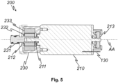
- FIG. 5 shows a schematic sectional drawing of another drive assembly 200 according to the invention.
- the illustrated drive assembly 200 comprises, like the one in Figure 4
- the drive assembly 200 shown includes a motor assembly 210 with a motor shaft 211 rotatable about a drive axis AA and an angular position sensor 213. Furthermore, a supply line 130 for supplying the motor assembly 210 with energy and/or control signals is shown.
- the motor shaft 211 on the side of the motor assembly 210 facing away from the angular position sensor 213 is directly and rigidly connected to a brake shaft 231 of a brake assembly 230 that can rotate about the drive axis AA, for example by the motor shaft 211 being coaxially inserted into a recess 212 in the brake shaft 231 and pressed therewith.
- a rotor 232 in particular a cylindrical one, is mounted on the brake shaft 231 shown, for example coaxially to the brake shaft 231.
- the rotor 232 shown which comprises a permanent magnet for example, is arranged, in particular coaxially, in a stator 233, for example a cylindrical one, which can be magnetized by the rotor 232.
- the rotor 232 and the stator 233 together form a hysteresis brake.
- FIG 6 shows a schematic sectional drawing of a brake assembly 230 according to the invention.
- the brake assembly 230 shown comprises a brake shaft 231 which is rotatable about a drive axis AA and is guided by a bearing 235.
- the brake shaft 231 shown is rigidly connected to a worm shaft 222 of a gear assembly (not shown), for example formed integrally therewith.
- the brake assembly 230 shown comprises a rotor 232 and a stator 233 which together form a hysteresis brake and as in Figure 3 shown can be arranged and designed with the difference that in Figure 4 the rotor 232 is spaced from the brake shaft 231 by a spacer 234.
- the spacer 234 for example made of a polymer, is shaped in the example shown such that the spacer 234 spaces the rotor 232 from both the brake shaft 231 and the bearing 235.
- the brake assembly 230 shown is enclosed by a housing 236, which is composed of two plastic half-shells, for example.
- FIG. 7 shows a schematic sectional drawing of another drive system 100 according to the invention. Components that are already in Figure 1 are provided with the same reference numerals as there and will not be described again.
- the spindle assembly 110 shown comprises a guide bush 112 for guiding a threaded spindle (not shown).
- the threaded spindle which can rotate about a spindle axis SA, is mechanically coupled to a worm wheel 223 of a worm gear 221 via a coupling assembly 240, for example with an overload clutch.
- the worm wheel 223 shown is mechanically coupled to a worm shaft (not shown) of the worm gear 221, the worm shaft being rotatable about a drive axis AA and, in particular, rigidly and/or coaxially, connected to a motor shaft 211 of a motor assembly 210.
- Both the threaded spindle and the worm shaft can each be mounted on at least one bearing 235.
- the angle ⁇ enclosed by the spindle axis SA and the drive axis AA is approximately 75°.
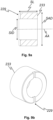
- Figure 8 shows a schematic representation of a rotor 232 according to the invention on a brake shaft 231 as a section along the drive axis AA ( Fig. 8a ) and as perspective Depiction ( Fig. 8b ).
- the rotor 232 is, for example, glued directly to the brake shaft 231.
- the rotor 232 shown is cylindrical and has, for example, a rotor length RL of 12.5 mm, a rotor inner diameter RID of 5.95 mm and/or a rotor outer diameter RAD of 13.5 mm.
- the rotor 232 can, for example, consist of a neodymium-iron-boron alloy, in particular with a nickel-copper coating.
- the brake shaft 231 has, for example, a section 239 for positive connection with a worm shaft of a gear assembly (not shown) with respect to rotation about the drive axis AA.
- the section 239 is designed, for example, as a gear wheel.
- FIG. 9 shows a schematic representation of a stator 233 according to the invention as a section along the drive axis AA ( Fig. 9a ) and as a perspective representation ( Fig. 9b ).
- the stator 233 shown is essentially cylindrical and has, for example, a stator length SL of 13 mm, a stator inner diameter SID of 14.5 mm and/or a stator outer diameter of 23 mm.
- the stator 233 can, for example, consist of an aluminum-nickel-copper alloy.
- FIG 10 shows a schematic representation of a manufacturing method 300 according to the invention for a drive system 100.
- the manufacturing method 300 initially comprises applying 310 an adhesive to a brake shaft 231 and/or a rotor 232 for a hysteresis brake 237 for the drive system 100.
- the next step involves attaching 320 the rotor 232 directly to the brake shaft 231, for example by pushing the rotor 232 coaxially onto the brake shaft 231.
- the rotor 232 is bonded 330 to the brake shaft 231 using the adhesive.
- the further manufacture of the hysteresis brake and the drive system can be carried out, for example, using standard manufacturing methods.
Landscapes
- Connection Of Motors, Electrical Generators, Mechanical Devices, And The Like (AREA)
- Gear Transmission (AREA)
- Power-Operated Mechanisms For Wings (AREA)
- Transmission Devices (AREA)
Description
- Die Erfindung betrifft ein motorisiertes Antriebssystem, insbesondere zur Betätigung einer Tür, gemäß dem Oberbegriff des Anspruchs 1. Die Erfindung betrifft ferner eine Verwendung des Antriebssystems zur Betätigung einer Tür, insbesondere einer Fahrzeugtür, und ein Herstellungsverfahren für ein Antriebssystem.
- Aus dem Stand der Technik sind Antriebssysteme zur, insbesondere elektromechanischen Ansteuerung beispielsweise von Türen, insbesondere von Fahrzeugtüren und Fahrzeugklappen, bekannt. Dabei wird eine Kraft eines Elektromotors, beispielsweise über eine Gewindespindel, an die Fahrzeugtür übertragen. Ferner können die Antriebssysteme beispielsweise eine Kupplung zum Schutz der Fahrzeugtür, insbesondere eines Anbindungselements des Antriebssystems an die Fahrzeugtür, vor Überlastung, eine Bremse zum Halten der Fahrzeugtür in einer bestimmten Position, ein Getriebe zur Anpassung der übertragenen Kraft und Drehzahl und/oder ein Lager zur Aufnahme von Kräften, die von Seiten der Fahrzugtür in das Antriebssystem eingegeben werden, umfassen.
- Ein gattungsgemäßes Antriebssystem wird beispielsweise in der Druckschrift
EP1940012A1 beschrieben. Für einen kompakten Aufbau und eine geringe Geräuschentwicklung des Antriebssystems schlägtEP 1940012 A1 die Verwendung einer Hysteresebremse für ein gattungsgemäßes Antriebssystem vor. - Ein weiteres gattungsgemäßes Antriebssystem wird in der Druckschrift
EP 1664470 B1 beschrieben.EP 1664470 B1 offenbart ein gattungsgemäßes Antriebssystem und ein verringertes Bauvolumen durch eine exakte Lagerung sowie axiale Führung und Ausrichtung der Bauteile des Antriebssystems. Weitere gattungsgemäße Antriebssysteme sind aus den DruckschriftenEP 2 543 808 A1 ,EP 032 020 A1 DE 10 2011 082 540 A1 bekannt. - Bei gattungsgemäßen Antriebssystemen besteht das Problem, dass im Betrieb mitunter bzw. kurzzeitig sehr hohe Kräfte, beispielsweise von einer von dem Antriebssystem betätigten Tür, in das Antriebssystem eingeleitet werden, beispielsweise weil eine Kraft, zum Beispiel durch einen Benutzer, mit einem wesentlich größeren Hebel bezüglich einer Drehachse der Tür an die Tür angreift als das Antriebssystem. Diese Kräfte können empfindliche Baugruppen des Antriebssystems, beispielsweise einen Motor oder eine Bremse beschädigen. Gleichzeitig können die Baugruppen, insbesondere durch Kosten- und Bauraumbeschränkungen auch nicht beliebig voluminös und/oder stabil ausgelegt werden, sodass es zu einem vorzeitigen Versagen der Antriebssysteme kommen kann.
- Aufgabe der Erfindung ist es daher, ein Antriebssystem, insbesondere zur Betätigung einer Tür, beispielsweise einer Fahrzeugtür, und ein Herstellungsverfahren für ein Antriebssystem zu schaffen, das besonders zuverlässig, platzsparend und gleichzeitig kostengünstig ist.
- Der Gegenstand der vorliegenden Erfindung stellt ein Antriebssystem bereit, das diese Aufgabe erfindungsgemäß entsprechend den Merkmalen des Anspruches 1 löst. Ebenso wird die Aufgabe durch eine Verwendung entsprechend den Merkmalen des Anspruches 9 und ein Herstellungsverfahren gemäß den Merkmalen des Anspruchs 10 gelöst. Vorteilhafte Ausgestaltungen ergeben sich aus den abhängigen Ansprüchen.
- Ein erfindungsgemäßes motorisiertes Antriebssystem, insbesondere zur Betätigung einer Tür, beispielsweise einer Fahrzeugtür, umfasst zumindest eine Getriebebaugruppe mit einer Spindelachse und einer Antriebsachse. Die Getriebebaugruppe ist zur Übersetzung einer Rotationsbewegung um die Antriebsachse in eine Rotationsbewegung um die Spindelachse ausgelegt. Das Antriebssystem umfasst zumindest eine Spindelbaugruppe, insbesondere zur Betätigung der Tür, mit einer um eine Spindelachse drehbaren Gewindespindel, wobei die Gewindespindel mit einem um die Spindelachse rotierbaren Teil der Getriebebaugruppe mechanisch gekoppelt ist. Das Antriebssystem umfasst zumindest eine Antriebsbaugruppe zum Antrieb der Gewindespindel mit einer Antriebswelle. Die Antriebswelle ist mit einem um die Antriebsachse rotierbaren Teil der Getriebebaugruppe mechanisch gekoppelt.
- Der Begriff "Tür" im Sinne der vorliegenden Erfindung umfasst jegliche Vorrichtung zum reversiblen Verschließen oder zumindest teilweisen Überdecken, Abschatten oder Abdecken zumindest eines Abschnitts und insbesondere einer Zugangsöffnung eines technischen Gerätes oder eines Gebäudes. Neben Türen für den Zugang von Personen sind beispielsweise auch Türen an Be- und/oder Entladungsöffnungen und/oder Lüftungsöffnungen, insbesondere auch Fenster, von dem Begriff "Tür" umfasst. Eine "Fahrzeugtür" im Sinne der Erfindung umfasst neben Türen für den Zugang von Passagieren zu dem Fahrzeug beispielsweise auch Kofferraumklappen und Motorhauben oder sonstige öffenbare Flächenabschnitte des Fahrzeugs, wie beispielsweise Gepäckklappen eines Reisebusses. Von dem Begriff "Fahrzeug" werden im Sinne der Erfindung insbesondere Land-, Wasser- und Luftfahrzeuge umfasst.
- Der Ausdruck "mechanisch gekoppelt" im Sinne der vorliegenden Erfindung umfasst jegliche Kopplung, die zur Übertragung einer mechanischen Kraft und/oder eines Drehmoments ausgelegt ist. Eine solche Kopplung kann beispielsweise durch eine stofflich und/oder körperlich verbundene, insbesondere starre, Verbindung und/oder eine magnetische Verbindung zur Übertragung von Bewegungsenergie vermittelt sein.
- Die Spindelachse und die Antriebsachse sind so angeordnet, dass sie nicht koaxial zueinander sind. Die Antriebsbaugruppe ist seitlich von der Spindelachse angeordnet. Eine nicht koaxiale Anordnung von Spindelachse und Antriebsachse verhindert vorteilhafterweise, dass eine, beispielsweise von einer von dem Antriebssystem betätigten Tür, entlang der Spindelachse in das Antriebssystem eingeleitete Kraft entlang der Antriebsachse weitergeleitet wird. Eine nicht koaxiale Anordnung führt zu einer mechanischen Entkopplung oder zumindest Teilentkopplung der Antriebsbaugruppe von der Spindelbaugruppe und damit zum Schutz der Antriebsbaugruppe vor Kraftbeaufschlagung über die Spindelbaugruppe entlang der Spindelachse. Dadurch werden an der Antriebsachse angeordnete Baugruppen des Antriebssystems, insbesondere eine Antriebsbaugruppe, vor diesen Kräften geschützt. Weiterhin können die an der Antriebsachse angeordneten Baugruppen seitlich von der Spindelachse, insbesondere neben entlang der Spindelachse angeordneten Baugruppen, angeordnet sein. Dadurch werden die seitlich angeordneten Baugruppen zusätzlich vor entlang der Spindelachse eingeleiteten Kräften geschützt. Aufgrund der aus der geringeren mechanischen Belastung resultierenden geringeren Anforderung von mechanischer Belastungsfähigkeit an das Material in Art, Struktur, Volumen und/oder Form kann das Antriebssystem, insbesondere bezüglich seiner Länge entlang der Spindelachse, besonders kompakt und gleichzeitig kostengünstig aufgebaut sein. Durch einen kompakten Aufbau eignet sich das Antriebssystem besonders gut für Fahrzeugtüren, da in Fahrzeugen, beispielsweise in Automobilen, häufig nur ein geringer Bauraum zur Verfügung steht.
- Die Spindelachse und die Antriebsachse schließen einen Winkel, der von 45° bis 90°, bevorzugt von 60° bis 90°, besonders bevorzugt 90° beträgt, ein. Erfindungsgemäß ist der "Winkel" der kleinere der beiden Winkel, die in deren Schnittpunkt - gegebenenfalls nach einer Parallelverschiebung zumindest einer der Achsen - zwischen den beiden Achsen liegen. Je näher der Winkel an 90° liegt, desto effizienter kann eine Drehbewegung um die Antriebsachse in eine Drehbewegung um die Spindelachse übersetzt werden, wodurch das Antriebssystem besonders effizient und zuverlässig arbeiten kann. Insbesondere bei einem Winkel von 90° können kostengünstige und einfach zu beschaffende Standard-Getriebekomponenten verwendet werden.
- Die zumindest eine Antriebsbaugruppe umfasst zumindest eine Motorbaugruppe zum Antrieb einer Drehbewegung der Gewindespindel um die Spindelachse mit einer um die Antriebsachse drehbaren Motorwelle. Die Motorwelle kann beispielsweise von einem Elektromotor angetrieben werden. Die Motorwelle ist starr mit der Antriebswelle verbunden und kann von der Antriebswelle umfasst sein. Insbesondere kann die Motorwelle ein Teil der Antriebswelle oder mit der Antriebswelle identisch sein.
- Die zumindest eine Getriebebaugruppe kann ein Schneckengetriebe zur Übersetzung einer Rotationsbewegung um die Antriebsachse in eine Rotationsbewegung um die Spindelachse umfassen. Ein Schneckengetriebe bietet die Vorteile eines besonders geräuscharmen Betriebs und einer besonders hohen Belastbarkeit, sodass sich auch hohe Drehmomente zuverlässig übertragen lassen. Ein geräuscharmer Betrieb ist insbesondere für den Einsatz bei Fahrzeugtüren hochpreisiger Fahrzeuge von Vorteil, da hierdurch einem Kunden eine hohe Wertigkeit vermittelt wird.
- Das Schneckengetriebe kann eine um die Antriebsachse rotierbare und mit der Antriebswelle mechanisch gekoppelte Schneckenwelle und ein um die Spindelachse rotierbares und mit der Gewindespindel mechanisch gekoppeltes Schneckenrad umfassen. Durch diese Ausgestaltung kann von dem Schneckengetriebe bei besonders kompakter Bauform eine Rotationsbewegung der Antriebswelle um die Antriebsachse in eine Rotationsbewegung der Gewindespindel um die Spindelachse übersetzt werden. Erfindungsgemäß können das Schneckenrad und die Schneckenwelle auch gegeneinander vertauscht sein.
- Die Schneckenwelle kann von der Antriebswelle umfasst und/oder starr mit der Antriebswelle verbunden sein. Insbesondere kann die Schneckenwelle ein Teil der Antriebswelle oder mit der Antriebswelle identisch sein.
- Die Schneckenwelle kann starr, insbesondere formschlüssig und/oder stoffschlüssig, und/oder koaxial, mit einer Motorwelle einer Motorbaugruppe und/oder einer Bremswelle einer Bremsbaugruppe verbunden sein. Dadurch wird eine besonders effiziente und zuverlässige Drehmomentübertragung zwischen der Motorwelle und/oder Bremswelle und der Schneckenwelle ermöglicht. Beispielsweise kann ein Abschnitt der Motorwelle und/oder Bremswelle bezüglich einer Rotation um die Antriebsachse formschlüssig mit einem Abschnitt der Schneckenwelle zusammenwirken.
- Die zumindest eine Antriebsbaugruppe umfasst zumindest eine Bremsbaugruppe zum Abbremsen einer Drehbewegung der Gewindespindel um die Spindelachse mit einer um die Antriebsachse drehbaren und bevorzugt durch ein Lager geführten Bremswelle. Durch die Bremsbaugruppe kann eine zu schnelle Bewegung, beispielsweise einer von dem Antriebssystem betätigten Tür, die einen Benutzer verletzen und/oder die Tür beschädigen könnte, verhindert werden. Insbesondere kann die Tür durch die Bremsbaugruppe in einer bestimmten Stellung gehalten werden, in der die Tür ohne Bremsbaugruppe, beispielsweise aufgrund der auf sie wirkenden Schwerkraft nicht verharren würde. Auch dadurch können Verletzungen eines Benutzers und/oder Beschädigungen der Tür vermieden werden.
- Die Bremsbaugruppe ist an einer der Getriebebaugruppe zugewandten Seite der Motorbaugruppe, insbesondere zwischen der Getriebebaugruppe und der Motorbaugruppe, angeordnet. Im Gegensatz zu einer Anordnung der Bremsbaugruppe an der der Getriebebaugruppe abgewandten Seite der Motorbaugruppe ergeben sich daraus die Vorteile, dass an der der Getriebebaugruppe abgewandten Seite der Motorbaugruppe Steuerungskomponenten und/oder Sensoren, die durch von der Bremsbaugruppe und/oder Getriebebaugruppe erzeugte Magnetfelder, Wärme und/oder Vibrationen negativ beeinflusst werden könnten, gefahrlos angeordnet werden können. Die Motorbaugruppe kann somit die Steuerungskomponenten und/oder Sensoren gegen die Magnetfelder, Wärme und/oder Vibrationen abschirmen, sodass keine separate Abschirmung notwendig ist und ein besonders kostengünstiger und kompakter Aufbau des Antriebssystems erreicht wird. Weiterhin sind die Steuerungskomponenten und/oder Sensoren auf der der Getriebebaugruppe abgewandten
- Seite, beispielsweise zur Verbindung mit anderen Komponenten oder zur Wartung, leichter zugänglich als auf der der Getriebebaugruppe zugewandten Seite.
- Die Motorbaugruppe umfasst einen Winkelpositionssensor, insbesondere einen Hall-Sensor, zur Messung einer Winkelposition der Motorwelle relativ zu der Motorbaugruppe, wobei der Winkelpositionssensor an einer der Bremsbaugruppe abgewandten Seite der Motorbaugruppe angeordnet ist. Ein Winkelpositionssensor, insbesondere ein Hall-Sensor, kann durch magnetische Felder leicht gestört werden, sodass eine Anordnung an der der Bremsbaugruppe abgewandten Seite der Motorbaugruppe für eine zuverlässige Messung besonders vorteilhaft ist. Durch den Winkelpositionssensor kann vorteilhafterweise eine Winkelposition der Gewindespindel und somit eine Position einer von dem Antriebssystem betätigten Komponente, beispielsweise ein Öffnungszustand einer Tür, einfach, präzise und zuverlässig, beispielsweise mit Hilfe einer Kalibrierungsfunktion, bestimmt werden.
- Die Bremsbaugruppe kann beispielsweise eine mechanische Reibbremse, beispielsweise eine Scheibenbremse und/oder eine Filzbremse umfassen. Eine mechanische Reibbremse bietet die Vorteile geringer Herstellungskosten und einer einfachen Montage. Die Bremsbaugruppe kann eine elektromagnetische Bremse, beispielsweise eine Bremse mit einem schaltbar bestromten Elektromagneten umfassen. Eine elektromagnetische Bremse bietet den Vorteil, dass ihre Funktion elektrisch, beispielsweise durch Ein- und/oder Ausschalten eines Elektromagneten gesteuert werden kann.
- Das Lager kann beispielsweise ein Gleitlager und/oder Wälzlager, insbesondere ein Kugellager umfassen. Durch das Lager werden vorteilhafterweise Bewegungen der Bremswelle radial zu ihrer Drehachse, die zum Beispiel die Funktion der Bremsbaugruppe und/oder der Getriebebaugruppe beeinträchtigen könnten, verhindert.
- Die Bremswelle ist starr mit der Antriebswelle verbunden und kann von der Antriebswelle umfasst sein. Insbesondere kann die Bremswelle ein Teil der Antriebswelle oder mit der Antriebswelle identisch sein.
- Die Bremswelle kann mit der Motorwelle der Motorbaugruppe mechanisch gekoppelt, besonders bevorzugt starr und/oder koaxial verbunden, sein. Durch eine starre und/oder koaxiale Verbindung wird ein besonders einfacher Aufbau des Antriebssystems und eine besonders hohe Bremswirkung ermöglicht. Beispielsweise kann ein Abschnitt der Motorwelle mit einem Abschnitt der Bremswelle verpresst sein.
- Die Bremswelle kann mit der Motorwelle im Betrieb der Antriebsvorrichtung lösbar verbunden sein, beispielsweise durch eine Freilaufkupplung und/oder eine, insbesondere elektrisch, schaltbare Kupplung zum Trennen der Bremswelle von der Motorwelle, während die Gewindespindel von der Motorbaugruppe angetrieben wird. Dadurch kann das Antriebssystem energieeffizienter arbeiten, und/oder die Motorbaugruppe kann leistungsschwächer und somit kleiner, leichter und/oder kostengünstiger ausgelegt sein. Eine im Betrieb der Antriebsvorrichtung lösbare Verbindung der Motorwelle mit der Bremswelle kann beispielsweise als eine Bremsanordnung, wie sie in der Druckschrift
DE102014212863A1 beschrieben ist, ausgestaltet sein. - Die Bremsbaugruppe umfasst eine Hysteresebremse, insbesondere mit zumindest einem mit der Bremswelle starr verbundenen, bevorzugt verklebten und/oder verpressten, Rotor und zumindest einem an einem Gehäuse der Bremsbaugruppe ortsfest angeordneten Stator, wobei der Rotor zumindest einen Permanentmagneten umfasst, durch den der Stator magnetisierbar ist. Alternativ kann der Stator zumindest einen Permanentmagneten umfassen, durch den der Rotor magnetisierbar ist. Ist der Rotor mit der Bremswelle verklebt, lässt sich die Hysteresebremse besonders einfach herstellen. Ist der Rotor mit der Bremswelle verpresst, ergibt sich daraus eine besonders langzeitstabile Verbindung, insbesondere gegenüber chemischen Lösemitteln, und die Hysteresebremse kann in besonders engen Toleranzen gefertigt sein.
- Eine Hysteresebremse bietet die Vorteile, dass sie geruchlos und geräuschlos arbeiten kann und, insbesondere in einem für das Antriebssystem relevanten Umfang von bis zu 20 Millionen Umdrehungen, verschleißbeständiger ist als mechanische Reibbremsen. Ferner benötigt eine Hysteresebremse nur einen geringen Bauraum entlang der Antriebsachse. Außerdem hängt das Brems-Drehmoment einer Hysteresebremse im Vergleich zu einer mechanischen Reibbremse, insbesondere in einem für das Antriebssystem relevanten Drehzahlbereich von 0 bis 3000 Umdrehungen pro Minute, weniger von einer Drehzahl der Bremswelle, und, insbesondere in einem für das Antriebssystem relevanten Temperaturbereich von -30 °C bis +80 °C, weniger von einer Umgebungstemperatur der Hysteresebremse ab. Ferner lässt sich das Brems-Drehmoment einer Hysteresebremse besser vorherbestimmen als bei einer mechanischen Reibbremse, wodurch eine kleine relative Toleranz des Brems-Drehmoments erreichbar ist. Durch eine Hysteresebremse kann daher das Brems-Drehmoment wesentlich genauer und mit geringeren Sicherheitsmargen auf das jeweilige Anwendungsgebiet des Antriebssystems ausgelegt sein als bei mechanischen Reibbremsen. Dadurch kann das Antriebssystem besonders effizient und zuverlässig arbeiten.
- Die Hysteresebremse kann beispielsweise wie in der Druckschrift
EP2192675A1 beschrieben ausgestaltet sein. - Der Rotor und/oder der Stator können im Wesentlichen zylinderförmig und/oder koaxial zur Bremswelle angeordnet sein. Der Rotor und/oder der Stator kann eine Anzahl von Ausnehmungen für eine bezüglich einer Rotation um die Antriebsachse formschlüssige Verbindung mit der Bremswelle oder einem Gehäuse der Bremsbaugruppe umfassen.
- Durch eine koaxiale Anordnung kann die Hysteresebremse, insbesondere wenn der Rotor und der Stator zylinderförmig sind, besonders kompakt aufgebaut sein. Besonders vorteilhaft ist der Rotor in dem Stator angeordnet, wobei insbesondere der Stator den Rotor radial zur Bremswelle vollständig überdeckt. Durch eine vollständige Überdeckung wird die Stärke eines magnetischen Feldes außerhalb des Stators minimiert, wodurch eine unerwünschte Magnetisierung weiterer Bauteile, beispielsweise eines Lagers, verringert oder sogar vollständig verhindert werden kann.
- Vorteilhafterweise ist der Rotor entlang der Bremswelle mittig in dem Stator angeordnet. Dadurch werden magnetische Kräfte, die entlang der Bremswelle auf den Rotor wirken und dadurch die Verbindung des Rotors mit der Bremswelle lösen könnten, minimiert.
- Wenn der Rotor innerhalb des Stators angeordnet ist, ist es besonders vorteilhaft, wenn der Rotor zumindest einen Permanentmagneten umfasst, durch den der Stator magnetisierbar ist. Im Betrieb der Hysteresebremse wird Wärme hauptsächlich in dem Bauteil erzeugt, das permanent ummagnetisiert wird. Ist dieses Bauteil der außenliegende Stator, kann diese Wärme leichter abgeführt werden, als wenn dieses Bauteil der innenliegende Rotor ist.
- Der Rotor und der Stator können, beispielsweise durch einen Luftspalt, voneinander beabstandet sein. Dadurch wird vorteilhaft verhindert, dass der Rotor und der Stator im Betrieb der Hysteresebremse aneinander reiben, wodurch es zu erhöhter Geräusch- und Wärmeentwicklung sowie erhöhtem Verschleiß kommen würde. Ferner kann durch die Wahl eines Spaltmaßes zwischen dem Rotor und dem Stator die Stärke der magnetischen Wechselwirkung dazwischen eingestellt und somit ein für das Antriebssystem geeignetes Brems-Drehmoment der Hysteresebremse eingestellt werden. Für typische Anwendungen des Antriebssystems hat sich beispielsweise ein Spaltmaß von 0,1 mm bis 1 mm, insbesondere von 0,2 mm bis 0,8 mm, beispielsweise 0,5 mm, als besonders vorteilhaft zur Erzeugung eines hohen Brems-Drehmoments bei mit üblichen Herstellungsmethoden erreichbaren Fertigungstoleranzen erwiesen.
- Die Stärke der magnetischen Wechselwirkung zwischen dem Rotor und dem Stator, und somit das Brems-Drehmoment, können durch die Wahl einer Länge des Rotors und/oder des Stators entlang der Bremswelle eingestellt werden. Für eine möglichst einfache Herstellung von Hysteresebremsen mit unterschiedlichen Brems-Drehmomenten ist es besonders vorteilhaft, wenn das Brems-Drehmoment durch die Wahl der Länge des innerhalb des Stators angeordneten Rotors eingestellt wird. Dadurch können durch die Variation eines einzigen Bauteils, nämlich des Rotors, unterschiedliche Brems-Drehmomente realisiert werden, ohne dass sich dadurch der von der Hysteresebremse beanspruchte Bauraum, der im Wesentlichen durch den Stator bestimmt wird, ändert. Für typische Anwendungen des Antriebssystems hat sich beispielsweise eine Länge des Stators von 5 mm bis 50 mm, insbesondere von 10 mm bis 20 mm, beispielsweise 13 mm, als besonders vorteilhaft erwiesen, wobei vorzugsweise die Länge des Rotors kleiner oder gleich der Länge des Stators, beispielsweise 12,5 mm bei einer Länge des Stators von 13 mm, gewählt ist.
- Der Rotor kann in dem Stator angeordnet sein und entlang der Bremswelle eine Rotorlänge und orthogonal zu der Bremswelle einen Rotoraußendurchmesser aufweisen, und der Stator kann entlang der Bremswelle eine Statorlänge und orthogonal zu der Bremswelle einen Statorinnendurchmesser aufweisen, wobei die genannten Maße vorzugsweise in folgendem Verhältnis zueinander stehen und besonders bevorzugt folgende Werte annehmen:
- a. Rotorlänge von 5 mm bis 50 mm, insbesondere von 10 mm bis 20 mm, beispielsweise 12,5 mm;
- b. Rotoraußendurchmesser von 5 mm bis 50 mm, insbesondere von 10 mm bis 20 mm, beispielsweise 13,5 mm;
- c. Statorlänge von 5 mm bis 50 mm, insbesondere von 10 mm bis 20 mm, beispielsweise 13 mm; und
- d. Statorinnendurchmesser von 5 mm bis 50 mm, insbesondere von 10 mm bis 20 mm, beispielsweise 14,5 mm.
- Dabei ist vorzugsweise die Rotorlänge kleiner oder gleich der Statorlänge gewählt, und/oder der Rotoraußendurchmesser und der Statorinnendurchmesser sind so gewählt, dass das Spaltmaß von 0,1 mm bis 1 mm, insbesondere von 0,2 mm bis 0,8 mm, beispielsweise 0,5 mm, beträgt.
- Durch die genannten Verhältnisse oder Maße wird mit üblichen Stator- und Rotormaterialien ein für übliche Anwendungen des Antriebssystems geeignetes Brems-Drehmoment erreicht, und das Antriebssystem kann mit üblichen Fertigungsmethoden und Fertigungstoleranzen kostengünstig hergestellt werden. Selbstverständlich können die Maße je nach Anwendungsanforderungen skaliert werden, wobei insbesondere das Spaltmaß konstant bleiben kann.
- Zwischen dem Rotor und der Bremswelle kann ein Abstandshalter, bevorzugt aus einem Polymer, angeordnet sein. Durch den Abstandshalter kann eine unerwünschte Magnetisierung der Bremswelle vermindert werden. Ferner kann der Abstandshalter auch eine Beabstandung von weiteren Bauteilen, die nicht magnetisiert werden sollen, beispielsweise einem Lager, sicherstellen.
- Der Rotor kann direkt auf der Bremswelle befestigt, beispielsweise aufgeklebt sein. Durch eine direkte Befestigung kann die Bremsbaugruppe besonders kostengünstig, insbesondere kostengünstiger als bei Verwendung eines Abstandhalters, hergestellt werden. Wenn die Bremswelle aus einem magnetisierbaren Material, beispielsweise aus Stahl, besteht, ergibt sich bei einer direkten Befestigung des Rotors darauf der zusätzliche Vorteil, dass durch eine Magnetisierung der Bremswelle die magnetische Wechselwirkung mit dem Stator und somit das Brems-Drehmoment verstärkt werden kann.
- Der Rotor kann durch ein Sicherungselement, beispielsweise einen Sicherungsring auf der Bremswelle, gegen eine Verschiebung entlang der Bremswelle gesichert sein.
- Die Bremsbaugruppe kann eine Wärmesenke zur Aufnahme bei einer Ummagnetisierung des Rotors oder Stators erzeugter Wärme umfassen. Durch die Wärmesenke kann vorteilhaft verhindert werden, dass sich wärmeempfindliche Teile des Antriebssystems zu stark erhitzen. Die Wärmesenke kann beispielsweise einen, insbesondere mit dem Stator wärmeleitend verbundenen, Metallblock, insbesondere mit Wärmeabstrahlrippen, umfassen.
- Der Rotor und/oder der Stator kann aus einer Anzahl von entlang der Bremswelle hintereinander angeordneten Modulen bestehen. Dadurch können vorteilhafterweise die magnetische Wechselwirkung zwischen Rotor und Stator und somit das Brems-Drehmoment der Bremsbaugruppe über die Anzahl der verwendeten Module für unterschiedliche Anwendungen des Antriebssystems eingestellt werden.
- Die Bremsbaugruppe kann eine Spule zur Verstärkung und/oder Schwächung eines Magnetfeldes des Permanentmagneten umfassen. Über einen die Spule durchfließenden elektrischen Strom können vorteilhafterweise die magnetische Wechselwirkung zwischen Rotor und Stator und somit das Brems-Drehmoment der Bremsbaugruppe, insbesondere während eines Betriebs des Antriebssystems, eingestellt werden. Beispielsweise kann das Brems-Drehmoment verringert werden, während ein Motor die Gewindespindel antreibt, damit das Antriebssystem effizienter arbeitet.
- Der Permanentmagnet kann aus einer Selten-Erd-Legierung, beispielsweise aus einer Neodym-Eisen-Bor-Legierung, und der Rotor oder der Stator aus einer Aluminium-Nickel-Kobalt-Legierung bestehen. Eine Neodym-Eisen-Bor-Legierung eignet sich besonders zur Herstellung eines Permanentmagneten mit einer hohen Magnetisierung, während sich eine Aluminium-Nickel-Kobalt-Legierung aufgrund ihrer geringen Koerzitiv-Feldstärke besonders gut durch einen Permanentmagneten ummagnetisieren lässt. Der Permanentmagnet kann vorteilhafterweise zumindest eine Korrosionsschutzbeschichtung, beispielsweise eine Nickel-, Nickel-Kupfer- und/oder Kunststoffbeschichtung, insbesondere eine Epoxidharzbeschichtung, aufweisen. Eine Kunststoffbeschichtung bietet, insbesondere wenn der Permanentmagnet aus einer in der Regel spröden Selten-Erd-Legierung besteht, den zusätzlichen Vorteil, dass sie den Permanentmagneten auch vor mechanischen Belastungen schützen kann.
- Die zumindest eine Motorbaugruppe kann von der zumindest einen Bremsbaugruppe beabstandet sein. Dadurch wird sichergestellt, dass sich diese beiden Baugruppen in ihrer Funktion nicht gegenseitig beeinträchtigen, beispielsweise durch eine Übertragung von Wärme und/oder Vibrationen. Insbesondere könnte es sonst passieren, dass ein Permanentmagnet der Bremsbaugruppe durch von der Motorbaugruppe abgegebene Wärme über seine Curie-Temperatur erhitzt wird und dadurch seine Magnetisierung verliert, wodurch die Bremswirkung der Bremsbaugruppe beeinträchtigt würde. Diese Gefahr besteht insbesondere bei Neodym-Eisen-Bor-Magneten, die eine relativ niedrige Curie-Temperatur im Bereich von 80 °C aufweisen.
- Beispielsweise kann die zumindest eine Getriebebaugruppe und/oder ein thermisches Isoliermittel zwischen der Motorbaugruppe und der Bremsbaugruppe angeordnet sein, und/oder die Motorbaugruppe und die Bremsbaugruppe können auf einander gegenüberliegenden Seiten der Spindelachse angeordnet sein.
- Das Antriebssystem kann zumindest eine Kupplungsbaugruppe zum Entkuppeln einer Drehbewegung der Gewindespindel um die Spindelachse von einer Drehbewegung der Antriebswelle um die Antriebsachse umfassen. Die Kupplungsbaugruppe kann bevorzugt eine Überlastkupplung, insbesondere zum Schutz einer von dem Antriebssystem betätigten Tür und/oder einer Anbindungsvorrichtung des Antriebssystems an die Tür, beispielsweise eines Kugelzapfens, vor Überlastung, umfassen.
- Besonders vorteilhaft kann das Antriebssystem so ausgelegt sein, dass die Überlastkupplung bei einer Belastung auslöst, die geringer ist als eine von der Tür, dem Anbindungselement und dem Antriebssystem jeweils ohne Beschädigung aufnehmbaren Maximalbelastung. Ferner ist das Antriebssystem vorteilhafterweise so ausgelegt, dass seine Maximalbelastung geringer ist als die jeweilige Maximalbelastung der Tür und des Anbindungselements. Dadurch wird sichergestellt, dass bei einer Fehlfunktion oder Fehlbedienung nicht die Tür oder das Anbindungselement, sondern nur das - in der Regel einfacher auszutauschende - Antriebssystem beschädigt wird.
- Die Spindelbaugruppe kann eine Führungsbuchse zur Führung und/oder ein Spindellager zur Lagerung der Gewindespindel umfassen. Durch die Führungsbuchse und/oder das Spindellager können unerwünschte Translationsbewegungen der Gewindespindel, die beispielsweise die Funktion einer mit der Gewindespindel verbundenen Kupplung und/oder eines Getriebes beeinträchtigen könnte, verhindert werden, sodass sich ein zuverlässiger Betrieb des Antriebssystems ergibt.
- Die vorliegende Erfindung umfasst eine Verwendung eines erfindungsgemäßen Antriebssystems zur Betätigung einer Tür, insbesondere einer Fahrzeugtür. Erfindungsgemäß kann das Antriebssystem auch zur Bewegung anderer Objekte, beispielsweise zur Höhenverstellung eines Tischs, verwendet werden.
- Ein erfindungsgemäßes Herstellungsverfahren für ein erfindungsgemäßes Antriebssystem, insbesondere zur Betätigung einer Tür, beispielsweise einer Fahrzeugtür, umfasst zumindest folgende Schritte:
- a. Aufbringen eines Klebstoffs auf eine Bremswelle und/oder einen Rotor für eine Hysteresebremse für das Antriebssystem;
- b. Anbringen des Rotors direkt auf der Bremswelle und
- c. stoffschlüssiges Verbinden des Rotors mit der Bremswelle durch den Klebstoff.
- Durch das Anbringen des Rotors direkt auf der Bremswelle wird ein besonders kompakter Aufbau der Hysteresebremse und somit des Antriebssystems erreicht. Das stoffschlüssige Verbinden sorgt für eine stabile und dauerhafte Befestigung des Rotors an der Bremswelle. Der Klebstoff kann insbesondere so gewählt sein, dass eine dauerhaft elastische Verbindung zwischen dem Rotor und der Bremswelle entsteht, sodass mögliche Vibrationen der Bremswelle, die den Rotor beschädigen könnten, nur gedämpft an diesen übertragen werden.
- Alternativ kann ein Herstellungsverfahren für ein, insbesondere erfindungsgemäßes, Antriebssystem folgende Schritte umfassen:
- a. Aufbringen eines Abstandshalters auf eine Bremswelle für eine Hysteresebremse für das Antriebssystem;
- b. Anbringen eines Rotors an dem Abstandshalter und
- c. Verpressen des Abstandshalters mit der Bremswelle und dem Rotor.
- Durch ein Verpressen kann eine besonders zuverlässige und langzeitstabile Verbindung des Abstandshalters mit der Bremswelle und dem Rotor erreicht werden. Insbesondere ist kein Klebstoff notwendig, der prozesstechnisch schwierig zu kontrollieren ist, beispielsweise weil seine Viskosität und/oder sein Trocknungsverhalten von Umgebungsparametern wie Temperatur und Feuchtigkeit abhängen. Außerdem kann ein Klebstoff durch Alterungsprozesse seine haftvermittelnde Wirkung zumindest teilweise einbüßen, wodurch die Langzeitstabilität einer Klebeverbindung gefährdet wird.
- Umfasst der Rotor einen Permanentmagneten, insbesondere einen Selten-Erd-Magneten, beispielsweise aus einer Neodym-Eisen-Bor-Legierung, ist der Rotor in der Regel zu spröde, um direkt mit der Bremswelle verpresst zu werden. Dieses Problem wird erfindungsgemäß dadurch gelöst, dass zwischen der Bremswelle und dem Rotor ein Abstandhalter, insbesondere aus einem Polymer, aufgebracht wird. Der Abstandshalter kann, beispielsweise durch plastische Verformung, beim Verpressen auftretende Kräfte zumindest teilweise aufnehmen, sodass der Rotor keinen Spannungen, die zu einer Beschädigung des Rotors führen könnten, ausgesetzt wird.
- Für einen besonders einfachen Aufbau des Antriebssystems und eine besonders zuverlässige Verbindung des Rotors mit der Bremswelle kann beispielsweise der Abstandshalter zylindrisch um die Bremswelle, insbesondere daran anliegend, aufgebracht und/oder der Rotor zylindrisch um den Abstandshalter, insbesondere daran anliegend, angebracht werden.
- Das Verpressen kann beispielsweise ein Aufweiten der Bremswelle umfassen, wodurch eine von der Bremswelle radial nach außen gerichtete Kraft auf den Abstandshalter und den Rotor wirkt, um diese miteinander und mit der Bremswelle zu verpressen. Das Verpressen kann beispielsweise eine Beaufschlagung des Abstandshalters, der beispielsweise als auf die Bremswelle aufgebrachte Buchse ausgestaltet sein kann, mit einer zur Bremswelle axialen Kraft umfassen, wodurch der Abstandshalter in einen Zwischenraum zwischen der Bremswelle und dem Rotor gepresst wird.
- Das Herstellungsverfahren kann ein Aufbringen eines Sicherungselements, insbesondere eines Sicherungsrings, auf die Bremswelle zur Sicherung des Rotors gegen eine Verschiebung entlang der Bremswelle umfassen.
- Weitere Vorteile, Ziele und Eigenschaften vorliegender Erfindung werden anhand nachfolgender Beschreibung und anliegender Zeichnungen erläutert, in welchen beispielhaft erfindungsgemäße Antriebssysteme dargestellt sind. Bauteile der Antriebssysteme, welche in den Figuren wenigstens im Wesentlichen hinsichtlich ihrer Funktion übereinstimmen, können hierbei mit gleichen Bezugsziffern gekennzeichnet sein, wobei diese Bauteile nicht in allen Figuren beziffert und erläutert sein müssen.
-
- Fig. 1
- eine schematische Zeichnung eines erfindungsgemäßen Antriebssystems;
- Fig. 2
- eine schematische Zeichnung eines weiteren erfindungsgemäßen Antriebssystems;
- Fig. 3
- eine schematische Schnittzeichnung einer erfindungsgemäßen Antriebsbaugruppe;
- Fig. 4
- eine schematische Schnittzeichnung einer weiteren erfindungsgemäßen Antriebsbaugruppe;
- Fig. 5
- eine schematische Schnittzeichnung einer weiteren erfindungsgemäßen Antriebsbaugruppe;
- Fig. 6
- eine schematische Schnittzeichnung einer erfindungsgemäßen Bremsbaugruppe;
- Fig. 7
- eine schematische Schnittzeichnung eines weiteren erfindungsgemäßen Antriebssystems;
- Fig. 8
- eine schematische Darstellung eines erfindungsgemäßen Rotors auf einer Bremswelle;
- Fig. 9
- eine schematische Darstellung eines erfindungsgemäßen Stators und
- Fig. 10
- eine schematische Darstellung eines erfindungsgemäßen Verfahrens.
-
Figur 1 zeigt eine schematische Zeichnung eines erfindungsgemäßen Antriebssystems 100 als Seitansicht (Fig. 1a ) und als Schnitt (Fig. 1b ) in der inFigur 1a markierten Ebene B-B. - Das dargestellte Antriebssystem 100 umfasst eine Spindelbaugruppe 110 und eine Antriebsbaugruppe 200, die durch eine Getriebebaugruppe 220 miteinander verbunden sind. Die Spindelbaugruppe 110 umfasst eine um eine Spindelachse SA rotierbare Gewindespindel (nicht dargestellt), und die Antriebsbaugruppe 200 umfasst eine um eine Antriebsachse AA rotierbare Antriebswelle 201. Die Gewindespindel und die Antriebswelle 201 sind über die Getriebebaugruppe 200 mechanisch miteinander gekoppelt, wobei die Getriebebaugruppe 220 zur Übersetzung einer Rotationsbewegung um die Antriebsachse AA in eine Rotationsbewegung um die Spindelachse SA ausgelegt ist.
- Die dargestellte Antriebsbaugruppe 200 umfasst eine Motorbaugruppe 210 zum Antrieb einer Drehbewegung der Gewindespindel um die Spindelachse SA und eine an einer der Getriebebaugruppe 220 zugewandten Seite der Motorbaugruppe 210 angeordnete Bremsbaugruppe 230 zum Abbremsen einer Drehbewegung der Gewindespindel um die Spindelachse SA. Dabei ist die Getriebebaugruppe 220 beispielsweise zwischen der Motorbaugruppe 210 und der Bremsbaugruppe 230 angeordnet.
- Die Antriebsachse AA und die Spindelachse SA sind im dargestellten Beispiel nicht koaxial angeordnet und schließen einen Winkel α ein, der beispielsweise 90° beträgt. Beispielsweise an der Antriebsbaugruppe 200 ist eine Versorgungsleitung 130, insbesondere zur Versorgung des Antriebssystems 100 mit Energie und/oder Steuersignalen, angeordnet. Beispielsweise an den Enden des Antriebssystems 100 entlang der Spindelachse SA ist zum Beispiel jeweils eine Anbindungsvorrichtung 120 angeordnet. Die Anbindungsvorrichtungen 120, die beispielsweise jeweils einen Kugelzapfen umfassen können, können zum Beispiel dazu ausgelegt sein, das Antriebssystem 100 mit einem Fahrzeug (nicht dargestellt) und einer Fahrzeugtür (nicht dargestellt) des Fahrzeugs zu verbinden, zu deren Betätigung das Antriebssystem 100 vorgesehen ist.
-
Figur 2 zeigt ein weiteres erfindungsgemäßes Antriebssystems 100 als Schnitt wie inFigur 1b . Im Gegensatz zum inFigur 1 dargestellten Antriebssystem 100 ist bei dem inFigur 2 dargestellten Antriebssystem 100 die Bremsbaugruppe 230 zwischen der Motorbaugruppe 210 und der Getriebebaugruppe 220 angeordnet. -
Figur 3 zeigt eine schematische Schnittzeichnung einer erfindungsgemäßen Antriebsbaugruppe 200. Die dargestellte Antriebsbaugruppe 200 umfasst eine Motorbaugruppe 210 zum Antrieb einer Drehbewegung einer Gewindespindel (nicht dargestellt) um eine Spindelachse SA mit einer um eine Antriebsachse AA drehbaren Motorwelle 211. - Die dargestellte Antriebsbaugruppe 200 umfasst eine Bremsbaugruppe 230 zum Abbremsen einer Drehbewegung der Gewindespindel um die Spindelachse SA mit einer um die Antriebsachse AA drehbaren und beispielsweise durch ein Lager 235 geführten Bremswelle 231. Die Bremsbaugruppe 230 umfasst beispielsweise eine Hysteresebremse 237. Die Bremswelle 231 ist beispielsweise über eine Schneckenwelle 222 einer Getriebebaugruppe 220 starr mit der Motorwelle 211 verbunden, wobei Bremswelle 231, Schneckenwelle 222 und Motorwelle 211 vorteilhafterweise koaxial zueinander angeordnet sind und/oder zusammen eine Antriebswelle der Antriebsbaugruppe 200 bilden.
- Im dargestellten Beispiel sind die Motorbaugruppe 210 und die Bremsbaugruppe 230 an einander gegenüberliegenden Seiten der Spindelachse SA und der Getriebebaugruppe 220 angeordnet.
- Die dargestellte Motorbaugruppe 210 umfasst einen Winkelpositionssensor 213, insbesondere einen Hall-Sensor, zur Messung einer Winkelposition der Motorwelle 211 relativ zu der Motorbaugruppe 210, wobei der Winkelpositionssensor 213 an einer der Bremsbaugruppe 230 abgewandten Seite der Motorbaugruppe 210 angeordnet ist.
-
Figur 4 zeigt eine schematische Schnittzeichnung einer weiteren erfindungsgemäßen Antriebsbaugruppe 200. Die dargestellte Antriebsbaugruppe 200 unterscheidet sich von der inFigur 3 dargestellten Antriebsbaugruppe 200 dadurch, dass die Bremsbaugruppe 230 zwischen der Motorbaugruppe 210 und der Getriebebaugruppe 220 angeordnet ist. -
Figur 5 zeigt eine schematische Schnittzeichnung einer weiteren erfindungsgemäßen Antriebsbaugruppe 200. Die dargestellte Antriebsbaugruppe 200 umfasst wie die inFigur 4 dargestellte Antriebsbaugruppe 200 eine Motorbaugruppe 210 mit einer um eine Antriebsachse AA drehbaren Motorwelle 211 und einen Winkelpositionssensor 213. Weiterhin ist eine Versorgungsleitung 130 zur Versorgung der Motorbaugruppe 210 mit Energie und/oder Steuersignalen dargestellt. - Im dargestellten Beispiel ist die Motorwelle 211 an der dem Winkelpositionssensor 213 abgewandten Seite der Motorbaugruppe 210 direkt und starr mit einer um die Antriebsachse AA drehbaren Bremswelle 231 einer Bremsbaugruppe 230 verbunden, beispielsweise indem die Motorwelle 211 koaxial in eine Vertiefung 212 in der Bremswelle 231 eingeführt und damit verpresst ist.
- Auf der dargestellten Bremswelle 231 ist ein, insbesondere zylindrischer, Rotor 232, beispielsweise koaxial zu der Bremswelle 231 angebracht. Der dargestellte Rotor 232, der beispielsweise einen Permanentmagneten umfasst, ist, insbesondere koaxial, in einem beispielsweise zylindrischen Stator 233 angeordnet, der durch den Rotor 232 magnetisiert werden kann. Der Rotor 232 und der Stator 233 bilden zusammen eine Hysteresebremse.
-
Figur 6 zeigt eine schematische Schnittzeichnung einer erfindungsgemäßen Bremsbaugruppe 230. Die dargestellte Bremsbaugruppe 230 umfasst eine um eine Antriebsachse AA drehbare Bremswelle 231, die durch ein Lager 235 geführt ist. Die dargestellte Bremswelle 231 ist mit einer Schneckenwelle 222 einer Getriebebaugruppe (nicht dargestellt) starr verbunden, beispielsweise einstückig damit ausgebildet. Die dargestellte Bremsbaugruppe 230 umfasst einen Rotor 232 und einen Stator 233, die zusammen eine Hysteresebremse bilden und wie inFigur 3 dargestellt angeordnet und ausgestaltet sein können mit dem Unterschied, dass inFigur 4 der Rotor 232 durch einen Abstandshalter 234 von der Bremswelle 231 beabstandet ist. Der Abstandshalter 234, beispielsweise aus einem Polymer, ist im dargestellten Beispiel so geformt, dass der Abstandshalter 234 den Rotor 232 sowohl von der Bremswelle 231 als auch von dem Lager 235 beabstandet. Die dargestellte Bremsbaugruppe 230 ist von einem Gehäuse 236, das beispielsweise aus zwei Kunststoffhalbschalen zusammengesetzt ist, umschlossen. -
Figur 7 zeigt eine schematische Schnittzeichnung eines weiteren erfindungsgemäßen Antriebssystems 100. Komponenten, die bereits inFigur 1 dargestellt sind, sind mit den gleichen Bezugszeichen wie dort versehen und werden nicht erneut beschrieben. Die dargestellte Spindelbaugruppe 110 umfasst eine Führungsbuchse 112 zur Führung einer Gewindespindel (nicht dargestellt). Die um eine Spindelachse SA drehbare Gewindespindel ist im dargestellten Beispiel über eine Kupplungsbaugruppe 240, beispielsweise mit einer Überlastkupplung, mit einem Schneckenrad 223 eines Schneckengetriebes 221 mechanisch gekoppelt. Das dargestellte Schneckenrad 223 ist mit einer Schneckenwelle (nicht dargestellt) des Schneckengetriebes 221 mechanisch gekoppelt, wobei die Schneckenwelle um eine Antriebsachse AA drehbar und, insbesondere starr und/oder koaxial, mit einer Motorwelle 211 einer Motorbaugruppe 210 verbunden ist. Sowohl die Gewindespindel als auch die Schneckenwelle können an jeweils zumindest einem Lager 235 gelagert sein. Im dargestellten Beispiel beträgt der von der Spindelachse SA und der Antriebsachse AA eingeschlossene Winkel α etwa 75°. -
Figur 8 zeigt eine schematische Darstellung eines erfindungsgemäßen Rotors 232 auf einer Bremswelle 231 als Schnitt entlang der Antriebsachse AA (Fig. 8a ) und als perspektivische Darstellung (Fig. 8b ). Der Rotor 232 ist beispielsweise direkt auf die Bremswelle 231 geklebt. Der dargestellte Rotor 232 ist zylinderförmig und hat beispielsweise eine Rotorlänge RL von 12,5 mm, einen Rotorinnendurchmesser RID von 5,95 mm und/oder einen Rotoraußendurchmesser RAD von 13,5 mm. Der Rotor 232 kann beispielsweise aus einer Neodym-Eisen-Bor-Legierung, insbesondere mit einer Nickel-Kupfer-Beschichtung, bestehen. - Die Bremswelle 231 weist beispielsweise einen Abschnitt 239 zur bezüglich einer Drehung um die Antriebsachse AA formschlüssigen Verbindung mit einer Schneckenwelle einer Getriebebaugruppe (nicht dargestellt) auf. Der Abschnitt 239 ist beispielsweise als Zahnrad ausgestaltet.
- Die Bremswelle 231 kann zumindest abschnittsweise hohl sein, sodass eine Motorwelle einer Motorbaugruppe (nicht dargestellt) und/oder eine Schneckenwelle einer Getriebebaugruppe (nicht dargestellt) zumindest teilweise in die Bremswelle 231 eingeführt und beispielsweise damit verpresst werden kann.
-
Figur 9 zeigt eine schematische Darstellung eines erfindungsgemäßen Stators 233 als Schnitt entlang der Antriebsachse AA (Fig. 9a ) und als perspektivische Darstellung (Fig. 9b ). Der dargestellte Stator 233 ist im Wesentlichen zylinderförmig und hat beispielsweise eine Statorlänge SL von 13 mm, einen Statorinnendurchmesser SID von 14,5 mm und/oder einen Statoraußendurchmesser von 23 mm. Der Stator 233 kann beispielsweise aus einer Aluminium-Nickel-Kupfer-Legierung bestehen. - Der dargestellte Stator 233 weist eine Anzahl von, beispielsweise zwei, Ausnehmungen 229 zur bezüglich einer Drehung um die Antriebsachse AA formschlüssigen Verbindung des Stators 233 mit einem Gehäuse einer Bremsbaugruppe (nicht dargestellt) auf.
-
Figur 10 zeigt eine schematische Darstellung eines erfindungsgemäßen Herstellungsverfahrens 300 für ein Antriebssystem 100. Das Herstellungsverfahren 300 umfasst zunächst ein Aufbringen 310 eines Klebstoffs auf eine Bremswelle 231 und/oder einen Rotor 232 für eine Hysteresebremse 237 für das Antriebssystem 100. Beispielsweise als nächster Schritt erfolgt ein Anbringen 320 des Rotors 232 direkt auf der Bremswelle 231, beispielsweise indem der Rotor 232 koaxial auf die Bremswelle 231 geschoben wird. Zum Beispiel im folgenden Schritt erfolgt ein stoffschlüssiges Verbinden 330 des Rotors 232 mit der Bremswelle 231 durch den Klebstoff. Die weitere Herstellung der Hysteresebremse und des Antriebssystems kann zum Beispiel mit fachüblichen Herstellungsmethoden erfolgen. -
- 100
- Antriebssystem
- 110
- Spindelbaugruppe
- 112
- Führungsbuchse
- 120
- Anbindungsvorrichtung
- 130
- Versorgungsleitung
- 200
- Antriebsbaugruppe
- 201
- Antriebswelle
- 210
- Motorbaugruppe
- 211
- Motorwelle
- 212
- Vertiefung
- 213
- Winkelpositionssensor
- 220
- Getriebebaugruppe
- 221
- Schneckengetriebe
- 222
- Schneckenwelle
- 223
- Schneckenrad
- 229
- Ausnehmung
- 230
- Bremsbaugruppe
- 231
- Bremswelle
- 232
- Rotor
- 233
- Stator
- 234
- Abstandshalter
- 235
- Lager
- 236
- Gehäuse
- 237
- Hysteresebremse
- 239
- Abschnitt
- 240
- Kupplungsbaugruppe
- 300
- Herstellungsverfahren
- 310
- Aufbringen
- 320
- Anbringen
- 330
- Verbinden
- RAD
- Rotoraußendurchmesser
- RID
- Rotorinnendurchmesser
- RL
- Rotorlänge
- SAD
- Statoraußendurchmesser
- SID
- Statorinnendurchmesser
- SL
- Statorlänge
- AA
- Antriebsachse
- SA
- Spindelachse
- α
- Winkel
Claims (10)
- Motorisiertes Antriebssystem (100), insbesondere zur Betätigung einer Tür, umfassenda. zumindest eine Getriebebaugruppe (220) mit einer Spindelachse (SA) und einer Antriebsachse (AA), wobei die Getriebebaugruppe (220) zur Übersetzung einer Rotationsbewegung um die Antriebsachse (AA) in eine Rotationsbewegung um die Spindelachse (SA) ausgelegt ist;b. zumindest eine Spindelbaugruppe (110) mit einer um eine Spindelachse (SA) drehbaren Gewindespindel, wobei die Gewindespindel mit einem um die Spindelachse (SA) rotierbaren Teil der Getriebebaugruppe (220) mechanisch gekoppelt ist, undc. zumindest eine Antriebsbaugruppe (200) zum Antrieb der Gewindespindel mit einer Antriebswelle (201), wobei die Antriebswelle (201) mit einem um die Antriebsachse (AA) rotierbaren Teil der Getriebebaugruppe (220) mechanisch gekoppelt ist,
wobei die zumindest eine Antriebsbaugruppe (200)d. zumindest eine Motorbaugruppe (210) zum Antrieb einer Drehbewegung der Gewindespindel um die Spindelachse (SA) mit einer um die Antriebsachse (AA) drehbaren und mit der Antriebswelle (201) starr verbundenen Motorwelle (211) unde. zumindest eine an einer der Getriebebaugruppe (220) zugewandten Seite der Motorbaugruppe (210) angeordnete Bremsbaugruppe (230) zum Abbremsen einer Drehbewegung der Gewindespindel um die Spindelachse (SA) mit einer um die Antriebsachse (AA) drehbaren und mit der Motorwelle (211) starr verbundenen Bremswelle (231) umfasst, wobei die Bremsbaugruppe (230) eine Hysteresebremse (237) umfasst,f dadurch gekennzeichnet, dass die Motorbaugruppe (210) einen Winkelpositionssensor (213) zur Messung einer Winkelposition der Motorwelle (211) relativ zu der Motorbaugruppe (210) umfasst, wobei der Winkelpositionssensor (213) an einer der Bremsbaugruppe (230) abgewandten Seite der Motorbaugruppe (210) angeordnet ist, wobeig die Spindelachse (SA) und die Antriebsachse (AA) nicht koaxial angeordnet sind, und die Antriebsbaugruppe (200) seitlich von der Spindelachse (SA) angeordnet ist, wobei die Spindelachse (SA) und die Antriebsachse (AA) einen Winkel (α), der von 45° bis 90° beträgt, einschließen. - Antriebssystem (100) nach Anspruch 1,
dadurch gekennzeichnet, dass
die Spindelachse (SA) und die Antriebsachse (AA) einen Winkel (α), der von 60° bis 90°, bevorzugt 90°, beträgt, einschließen. - Antriebssystem (100) nach Anspruch 1 oder 2,
dadurch gekennzeichnet, dass
der Winkelpositionssensor (213) einen Hall-Sensor umfasst. - Antriebssystem (100) nach einem der Ansprüche 1 bis 3,
dadurch gekennzeichnet, dassdie zumindest eine Getriebebaugruppe (220) ein Schneckengetriebe (221) zur Übersetzung einer Rotationsbewegung um die Antriebsachse (AA) in eine Rotationsbewegung um die Spindelachse (SA) umfasst, wobei das Schneckengetriebe (221) bevorzugta. eine um die Antriebsachse (AA) rotierbare und mit der Antriebswelle (201) mechanisch gekoppelte Schneckenwelle (222) undb. ein um die Spindelachse (SA) rotierbares und mit der Gewindespindel mechanisch gekoppeltes Schneckenrad (223) umfasst,wobei die Schneckenwelle (222) besonders bevorzugt von der Antriebswelle (201) umfasst und/oder starr und/oder koaxial mit einer Motorwelle (201) einer Motorbaugruppe (210) verbunden ist. - Antriebssystem (100) nach einem der Ansprüche 1 bis 4,
dadurch gekennzeichnet, dass
die Hysteresebremse (237) zumindest einen mit der Bremswelle (231) starr verbundenen Rotor (232) und zumindest einen an einem Gehäuse (236) der Bremsbaugruppe (230) ortsfest angeordneten Stator (233) umfasst, wobei der Rotor (232) zumindest einen Permanentmagneten umfasst, durch den der Stator (233) magnetisierbar ist, oder umgekehrt. - Antriebssystem (100) nach Anspruch 5,
dadurch gekennzeichnet, dass
der Rotor (232) und der Stator (233) im Wesentlichen zylinderförmig und koaxial zur Bremswelle (231) angeordnet sind, wobei der Rotor (232) in dem Stator (233) angeordnet ist und entlang der Bremswelle (231) eine Rotorlänge und orthogonal zu der Bremswelle (231) einen Rotoraußendurchmesser aufweist, und der Stator (233) entlang der Bremswelle (231) eine Statorlänge und orthogonal zu der Bremswelle (231) einen Statorinnendurchmesser aufweist, wobei die genannten Maße in folgendem Verhältnis zueinander stehen und bevorzugt folgende Werte annehmen:a. Rotorlänge (RL) von 5 mm bis 50 mm, bevorzugt von 10 mm bis 20 mm, besonders bevorzugt 12,5 mm;b. Rotoraußendurchmesser (RAD) von 5 mm bis 50 mm, bevorzugt von 10 mm bis 20 mm, besonders bevorzugt 13,5 mm;c. Statorlänge (SL) von 5 mm bis 50 mm, bevorzugt von 10 mm bis 20 mm, besonders bevorzugt 13 mm; undd. Statorinnendurchmesser (SID) von 5 mm bis 50 mm, bevorzugt von 10 mm bis 20 mm, besonders bevorzugt 14,5 mm. - Antriebssystem (100) nach Anspruch 5 oder 6,
dadurch gekennzeichnet, dass
der Permanentmagnet aus einer Neodym-Eisen-Bor-Legierung, insbesondre mit einer Korrosionsschutzbeschichtung, und der Rotor (232) oder der Stator (233) aus einer Aluminium-Nickel-Kobalt-Legierung besteht. - Antriebssystem (100) nach einem der Ansprüche 1 bis 7,
gekennzeichnet durch
zumindest eine Kupplungsbaugruppe (240) zum Entkuppeln einer Drehbewegung der Gewindespindel um die Spindelachse (SA) von einer Drehbewegung einer Antriebswelle (201) um die Antriebsachse (AA), wobei die Kupplungsbaugruppe (240) bevorzugt eine Überlastkupplung (241), insbesondere zum Schutz einer von dem Antriebssystem (100) betätigten Tür und/oder einer Anbindungsvorrichtung (120) des Antriebssystems (100) an die Tür vor Überlastung, umfasst. - Verwendung eines Antriebssystems (100) gemäß einem der Ansprüche 1 bis 8 zum Betätigen einer Tür, insbesondere einer Fahrzeugtür.
- Herstellungsverfahren (300) für ein Antriebssystem (100) gemäß einem der Ansprüche 1 bis 8 mit zumindest folgenden Schritten:a. Aufbringen (310) eines Klebstoffs auf eine Bremswelle (231) und/oder einen Rotor (232) für eine Hysteresebremse (237) für das Antriebssystem (100);b. Anbringen (320) des Rotors (232) direkt auf der Bremswelle (231) undc. stoffschlüssiges Verbinden (330) des Rotors (232) mit der Bremswelle (231) durch den Klebstoff.
Applications Claiming Priority (2)
| Application Number | Priority Date | Filing Date | Title |
|---|---|---|---|
| DE102018100562.8A DE102018100562A1 (de) | 2018-01-11 | 2018-01-11 | Motorisiertes antriebssystem, verwendung des antriebssystems zur betätigung einer tür, herstellungsverfahren für ein antriebssystem |
| PCT/EP2019/050681 WO2019138068A1 (de) | 2018-01-11 | 2019-01-11 | Motorisiertes antriebssystem, verwendung des antriebssystems zur betätigung einer tür, herstellungsverfahren für ein antriebssystem |
Publications (2)
| Publication Number | Publication Date |
|---|---|
| EP3737817A1 EP3737817A1 (de) | 2020-11-18 |
| EP3737817B1 true EP3737817B1 (de) | 2025-03-05 |
Family
ID=65031064
Family Applications (1)
| Application Number | Title | Priority Date | Filing Date |
|---|---|---|---|
| EP19700686.9A Active EP3737817B1 (de) | 2018-01-11 | 2019-01-11 | Motorisiertes antriebssystem, verwendung des antriebssystems zur betätigung einer tür, herstellungsverfahren für ein antriebssystem |
Country Status (8)
| Country | Link |
|---|---|
| US (1) | US11332969B2 (de) |
| EP (1) | EP3737817B1 (de) |
| JP (1) | JP7258033B2 (de) |
| KR (1) | KR102703980B1 (de) |
| CN (1) | CN111601941B (de) |
| DE (1) | DE102018100562A1 (de) |
| MX (1) | MX2020007398A (de) |
| WO (1) | WO2019138068A1 (de) |
Families Citing this family (22)
| Publication number | Priority date | Publication date | Assignee | Title |
|---|---|---|---|---|
| DE102017115183A1 (de) * | 2017-07-06 | 2019-01-10 | Edscha Engineering Gmbh | Antriebsvorrichtung für eine Fahrzeugklappe |
| DE102017128390A1 (de) * | 2017-11-30 | 2019-06-06 | U-Shin Deutschland Zugangssysteme Gmbh | Spindelantriebsbaugruppe sowie Fahrzeugklappe mit einer Spindelantriebsbaugruppe |
| DE102018220080A1 (de) * | 2018-11-22 | 2020-05-28 | Stabilus Gmbh | Kinematik für Fahrzeug-Klappe |
| DE102019102857A1 (de) | 2019-02-05 | 2020-08-06 | Brose Fahrzeugteile Se & Co. Kommanditgesellschaft, Bamberg | Antriebsstrang |
| JP7252058B2 (ja) * | 2019-05-27 | 2023-04-04 | 株式会社ユーシン | 車両用ドア支持装置 |
| US11713609B2 (en) | 2019-11-01 | 2023-08-01 | Magna Closures Inc. | Powered door unit with improved mounting arrangement |
| DE102020105716C5 (de) * | 2020-03-03 | 2024-08-29 | Edscha Engineering Gmbh | Stellantrieb mit einer Drehmomentbegrenzungsvorrichtung |
| KR102463882B1 (ko) * | 2021-01-11 | 2022-11-07 | 주식회사 광진 | 자동차용 측면도어의 개폐장치 |
| CN112728340B (zh) * | 2021-01-20 | 2025-01-28 | 航天科工微电子系统研究院有限公司 | 一种用于多系统共轴集成设计的两轴空心转台 |
| DE102021104891A1 (de) * | 2021-03-01 | 2022-09-01 | Stabilus Gmbh | Antriebssystem zum Öffnen und Schließen einer Kraftfahrzeugtür, Kraftfahrzeugtür mit dem Antriebssystem |
| CN113217576B (zh) * | 2021-05-14 | 2023-11-03 | 宁波华楷电子科技有限公司 | 一种用于电动尾门撑杆的新型阻尼结构 |
| US12221821B2 (en) * | 2021-09-29 | 2025-02-11 | U-Shin Deutschland Zugangssysteme Gmbh | Drive for a flap |
| DE102021131945A1 (de) * | 2021-12-03 | 2023-06-07 | Brose Fahrzeugteile Se & Co. Kommanditgesellschaft, Bamberg | Antriebseinheit zum motorischen Verstellen eines Verschlusselements eines Ktaftfahrzeugs |
| DE102022100369B3 (de) | 2022-01-10 | 2023-04-27 | Stabilus Gmbh | Elektromotor zum Antrieb einer Fahrzeugklappe, Verwendung und Verfahren zur Herstellung des Elektromotors |
| US20250379491A1 (en) * | 2022-02-16 | 2025-12-11 | Nidec Taiwan Corporation | Electric actuator |
| WO2023157108A1 (ja) * | 2022-02-16 | 2023-08-24 | ニデック株式会社 | 電動アクチュエータ |
| DE102022129941A1 (de) | 2022-11-11 | 2024-05-16 | Brose Fahrzeugteile Se & Co. Kommanditgesellschaft, Bamberg | Antriebseinheit zur motorischen Verstellung eines Verschlusselements eines Kraftfahrzeugs |
| KR102886826B1 (ko) * | 2023-07-05 | 2025-11-21 | 주식회사 일진 | 전동 도어 드라이브 장치용 브레이크 모듈 및 이를 포함하는 전동 도어 드라이브 장치 |
| KR102832204B1 (ko) * | 2023-07-10 | 2025-07-09 | 대동도어 주식회사 | 차량 도어의 자동 및 수동 개폐장치 |
| KR102859221B1 (ko) * | 2023-08-07 | 2025-09-15 | 피에이치에이 주식회사 | 오토도어 클로저 장치 |
| KR20250021716A (ko) * | 2023-08-07 | 2025-02-14 | 피에이치에이 주식회사 | 오토도어 클로저 장치 |
| DE102023121213A1 (de) * | 2023-08-09 | 2025-02-13 | Brose Fahrzeugteile Se & Co. Kommanditgesellschaft, Bamberg | Antriebseinheit zur motorischen Verstellung eines Verschlusselements eines Kraftfahrzeugs |
Citations (13)
| Publication number | Priority date | Publication date | Assignee | Title |
|---|---|---|---|---|
| WO2006039931A1 (en) | 2004-10-15 | 2006-04-20 | Linak A/S | A linear actuator |
| DE60112597T2 (de) | 2000-10-03 | 2006-06-08 | Linak A/S | Linearer stellantrieb |
| US20060270330A1 (en) | 2005-04-28 | 2006-11-30 | Kurt Schmid | Linear drive unit |
| EP1940012A1 (de) | 2006-12-27 | 2008-07-02 | Valeo Sicherheitssysteme GmbH | Selbsttätigeverstellvorrichtung für eine Kraftfahrzeugtür |
| CN201381734Y (zh) | 2009-03-26 | 2010-01-13 | 杭州三园工具有限公司 | 平开门机限位装置 |
| EP2192675A1 (de) | 2008-11-27 | 2010-06-02 | Valeo Sicherheitssysteme GmbH | Hysteresebremse |
| EP2543808A1 (de) | 2011-07-05 | 2013-01-09 | VALEO Sicherheitssysteme GmbH | Aktuatorvorrichtung zum automatischen Betätigen der Fahrzeugtür eines Kraftfahrzeugs |
| DE102011082540A1 (de) * | 2011-09-12 | 2013-03-14 | Stabilus Gmbh | Antriebseinrichtung |
| AU2014101008A4 (en) | 2014-08-26 | 2014-10-02 | Dongyang Linix Machine Electricity Co.,Ltd. | Brake Mechanism for Electric Sliding Door |
| EP2845979A1 (de) | 2013-07-05 | 2015-03-11 | Magna Closures Inc. | Antrieb für Garagentor |
| WO2015048876A1 (en) | 2013-10-01 | 2015-04-09 | Warren Industries Ltd. | Vehicle door control system |
| EP3032020A1 (de) | 2014-12-11 | 2016-06-15 | U-Shin Deutschland Zugangssysteme GmbH | Aktuatorvorrichtung zum automatischen Betätigen der Fahrzeugtür eines Kraftfahrzeugs |
| WO2016198196A1 (en) | 2015-06-08 | 2016-12-15 | Reac Ab | An electric motor arrangement adapted for use in an actuator and an actuator including the motor arrangement |
Family Cites Families (22)
| Publication number | Priority date | Publication date | Assignee | Title |
|---|---|---|---|---|
| KR200273545Y1 (ko) * | 2002-01-25 | 2002-04-25 | 주식회사 모아텍 | 소형 모터용 회전자 마그네트 |
| DE20313273U1 (de) | 2003-08-21 | 2004-09-30 | Brose Fahrzeugteile Gmbh & Co. Kg, Coburg | Antriebssystem für Verstelleinrichtungen in Kraftfahrzeugen |
| US7226111B2 (en) * | 2004-08-24 | 2007-06-05 | Hi-Lex Controls Inc. | Integrated spring actuator strut assembly |
| US20070151158A1 (en) * | 2006-01-03 | 2007-07-05 | Fenelon Paul J | Window lift mechanism |
| WO2009020610A1 (en) * | 2007-08-06 | 2009-02-12 | Strattec Power Access Llc | Linear drive actuator for a movable vehicle panel |
| US8366175B2 (en) * | 2010-04-29 | 2013-02-05 | Honda Motor Co., Ltd. | Door checker drive mechanism |
| DE102010043185A1 (de) * | 2010-10-29 | 2012-05-03 | Robert Bosch Gmbh | Werkzeugmaschinenbremsvorrichtung |
| DE102015110089A1 (de) * | 2014-06-27 | 2015-12-31 | Magna Closures Inc. | Elektromechanische Strebe mit integrierter Flexkupplung und Schlupfvorrichtung und zugehörige Kupplungs-/Kopplungs-Anordnung |
| DE102014212863B4 (de) | 2014-07-02 | 2020-08-20 | Stabilus Gmbh | Klappensteuerung |
| DE102014220414A1 (de) * | 2014-10-08 | 2016-04-14 | Brose Fahrzeugteile Gmbh & Co. Kg, Hallstadt | Permanentmagnetbremse für eine Antriebsvorrichtung zum Verstellen eines Fahrzeugteils |
| US10683691B2 (en) | 2016-04-07 | 2020-06-16 | Magna Closures Inc. | Power swing door actuator with integrated door check mechanism |
| DE102016206415A1 (de) | 2016-04-15 | 2017-10-19 | Stabilus Gmbh | Sicherheitsschaltung für einen Drehantrieb |
| EP3258148B1 (de) * | 2016-06-14 | 2020-05-06 | Hamilton Sundstrand Corporation | Drehbetätigungsmechanismus |
| US10711504B2 (en) * | 2016-08-16 | 2020-07-14 | Magna Closures Inc. | Power door presenter with latching feature |
| DE102016218226A1 (de) | 2016-09-22 | 2018-03-22 | Stabilus Gmbh | Stellvorrichtung |
| US11008780B2 (en) * | 2016-12-23 | 2021-05-18 | Magna Closures, Inc. | Power door presenter with latching feature |
| US10655378B2 (en) * | 2017-02-07 | 2020-05-19 | Magna Closures Inc. | Power side door actuator with rotating drive nut |
| US10801245B2 (en) * | 2017-10-18 | 2020-10-13 | Magna Closures Inc. | Power door with toothed rod crank mechanism |
| JP2019090258A (ja) * | 2017-11-15 | 2019-06-13 | アイシン精機株式会社 | ドアチェック装置 |
| US20200165856A1 (en) * | 2018-11-28 | 2020-05-28 | Magna Closures Inc. | Counterbalance strut for vehicle closure panel lift system having an active brake and method for counterbalance strut and system control |
| JP7088455B2 (ja) * | 2019-01-08 | 2022-06-21 | 三井金属アクト株式会社 | 車両サイドドアの開閉装置 |
| DE102019121644A1 (de) * | 2019-06-04 | 2020-12-10 | Inventus Engineering Gmbh | Verfahren zum Steuern von Türbewegungen einer Tür eines Kraftfahrzeugs und Kraftfahrzeugkomponente |
-
2018
- 2018-01-11 DE DE102018100562.8A patent/DE102018100562A1/de active Pending
-
2019
- 2019-01-11 MX MX2020007398A patent/MX2020007398A/es unknown
- 2019-01-11 JP JP2020538634A patent/JP7258033B2/ja active Active
- 2019-01-11 US US16/959,682 patent/US11332969B2/en active Active
- 2019-01-11 KR KR1020207022250A patent/KR102703980B1/ko active Active
- 2019-01-11 EP EP19700686.9A patent/EP3737817B1/de active Active
- 2019-01-11 WO PCT/EP2019/050681 patent/WO2019138068A1/de not_active Ceased
- 2019-01-11 CN CN201980008056.2A patent/CN111601941B/zh active Active
Patent Citations (13)
| Publication number | Priority date | Publication date | Assignee | Title |
|---|---|---|---|---|
| DE60112597T2 (de) | 2000-10-03 | 2006-06-08 | Linak A/S | Linearer stellantrieb |
| WO2006039931A1 (en) | 2004-10-15 | 2006-04-20 | Linak A/S | A linear actuator |
| US20060270330A1 (en) | 2005-04-28 | 2006-11-30 | Kurt Schmid | Linear drive unit |
| EP1940012A1 (de) | 2006-12-27 | 2008-07-02 | Valeo Sicherheitssysteme GmbH | Selbsttätigeverstellvorrichtung für eine Kraftfahrzeugtür |
| EP2192675A1 (de) | 2008-11-27 | 2010-06-02 | Valeo Sicherheitssysteme GmbH | Hysteresebremse |
| CN201381734Y (zh) | 2009-03-26 | 2010-01-13 | 杭州三园工具有限公司 | 平开门机限位装置 |
| EP2543808A1 (de) | 2011-07-05 | 2013-01-09 | VALEO Sicherheitssysteme GmbH | Aktuatorvorrichtung zum automatischen Betätigen der Fahrzeugtür eines Kraftfahrzeugs |
| DE102011082540A1 (de) * | 2011-09-12 | 2013-03-14 | Stabilus Gmbh | Antriebseinrichtung |
| EP2845979A1 (de) | 2013-07-05 | 2015-03-11 | Magna Closures Inc. | Antrieb für Garagentor |
| WO2015048876A1 (en) | 2013-10-01 | 2015-04-09 | Warren Industries Ltd. | Vehicle door control system |
| AU2014101008A4 (en) | 2014-08-26 | 2014-10-02 | Dongyang Linix Machine Electricity Co.,Ltd. | Brake Mechanism for Electric Sliding Door |
| EP3032020A1 (de) | 2014-12-11 | 2016-06-15 | U-Shin Deutschland Zugangssysteme GmbH | Aktuatorvorrichtung zum automatischen Betätigen der Fahrzeugtür eines Kraftfahrzeugs |
| WO2016198196A1 (en) | 2015-06-08 | 2016-12-15 | Reac Ab | An electric motor arrangement adapted for use in an actuator and an actuator including the motor arrangement |
Also Published As
| Publication number | Publication date |
|---|---|
| DE102018100562A1 (de) | 2019-07-11 |
| US11332969B2 (en) | 2022-05-17 |
| WO2019138068A1 (de) | 2019-07-18 |
| US20200370357A1 (en) | 2020-11-26 |
| KR102703980B1 (ko) | 2024-09-05 |
| KR20200106059A (ko) | 2020-09-10 |
| JP2021510402A (ja) | 2021-04-22 |
| CN111601941B (zh) | 2022-05-17 |
| JP7258033B2 (ja) | 2023-04-14 |
| MX2020007398A (es) | 2020-09-14 |
| EP3737817A1 (de) | 2020-11-18 |
| CN111601941A (zh) | 2020-08-28 |
Similar Documents
| Publication | Publication Date | Title |
|---|---|---|
| EP3737817B1 (de) | Motorisiertes antriebssystem, verwendung des antriebssystems zur betätigung einer tür, herstellungsverfahren für ein antriebssystem | |
| EP2679865B2 (de) | Baureihe von Antriebseinrichtungen | |
| EP3649376B1 (de) | Antriebsvorrichtung für eine fahrzeugklappe | |
| DE102008043173A1 (de) | Getriebe-Antriebseinheit mit einer Selbsthemmvorrichtung | |
| DE102010052920A1 (de) | Fahrwerkaktuator | |
| DE102013005732A1 (de) | Linearsteller | |
| DE102013005731A1 (de) | Linearsteller | |
| DE102019219002A1 (de) | Elektromechanische Bremsvorrichtung für ein Kraftfahrzeug | |
| DE102013000420A1 (de) | Antriebseinheit für eine Karusselltür mit einer integrierten Blockier- und/oder Bremseinrichtung | |
| EP2262989B1 (de) | Reibschaltkupplung sowie antriebssystem für die kühlung eines verbrennungsmotors eines fahrzeugs mit einer reibschaltkupplung | |
| DE102010013622B4 (de) | Antriebsvorrichtung für ein Stellelement eines Kraftfahrzeugs | |
| EP3404172B1 (de) | Sicherheitseinrichtung für schlösser | |
| DE102007039239A1 (de) | Elektromotor, insbesondere Stell- oder Antriebsmotor in Kraftfahrzeugen | |
| DE102019201952A1 (de) | Parksperre | |
| EP1928678B1 (de) | Antriebseinheit | |
| DE102013110334B4 (de) | Antriebsrad für ein Kleinfahrzeug, insbesondere Rollstuhl | |
| EP1958315B1 (de) | Sperrvorrichtung, getriebe-antriebseinheit beinhaltend eine solche sperrvorrichtung, sowie verfahren zur herstellung einer solchen getriebe-antriebseinheit | |
| DE102013206941A1 (de) | Lastdrehmomentsperre und Getriebe-Antriebseinrichtung mit einer Lastdrehmomentsperre | |
| DE102017210707A1 (de) | Antriebssystem | |
| DE202015004083U1 (de) | Reckeinrichtung | |
| EP1563587A1 (de) | Antriebsvorrichtung für verstelleinrichtungen in kraftfahrzeugen | |
| DE102014100719A1 (de) | Hinterachslenkung für Kraftfahrzeuge | |
| AT526237B1 (de) | Möbelantrieb | |
| DE102019111266A1 (de) | Handkraftaktuatorsystem für ein Steer-by-Wire System eines Fahrzeugs | |
| DE102017111397A1 (de) | Stellantrieb für ein kraftfahrzeug |
Legal Events
| Date | Code | Title | Description |
|---|---|---|---|
| STAA | Information on the status of an ep patent application or granted ep patent |
Free format text: STATUS: UNKNOWN |
|
| STAA | Information on the status of an ep patent application or granted ep patent |
Free format text: STATUS: THE INTERNATIONAL PUBLICATION HAS BEEN MADE |
|
| PUAI | Public reference made under article 153(3) epc to a published international application that has entered the european phase |
Free format text: ORIGINAL CODE: 0009012 |
|
| STAA | Information on the status of an ep patent application or granted ep patent |
Free format text: STATUS: REQUEST FOR EXAMINATION WAS MADE |
|
| 17P | Request for examination filed |
Effective date: 20200810 |
|
| AK | Designated contracting states |
Kind code of ref document: A1 Designated state(s): AL AT BE BG CH CY CZ DE DK EE ES FI FR GB GR HR HU IE IS IT LI LT LU LV MC MK MT NL NO PL PT RO RS SE SI SK SM TR |
|
| AX | Request for extension of the european patent |
Extension state: BA ME |
|
| RIN1 | Information on inventor provided before grant (corrected) |
Inventor name: MAZEPA, SERGEI Inventor name: HUEMMERICH, MAGNUS Inventor name: BOCHEN, MARIAN Inventor name: SCHMENGLER, MARCEL Inventor name: HOEFER, FLORIAN |
|
| DAV | Request for validation of the european patent (deleted) | ||
| DAX | Request for extension of the european patent (deleted) | ||
| P01 | Opt-out of the competence of the unified patent court (upc) registered |
Effective date: 20230509 |
|
| STAA | Information on the status of an ep patent application or granted ep patent |
Free format text: STATUS: EXAMINATION IS IN PROGRESS |
|
| 17Q | First examination report despatched |
Effective date: 20230619 |
|
| TPAC | Observations filed by third parties |
Free format text: ORIGINAL CODE: EPIDOSNTIPA |
|
| GRAP | Despatch of communication of intention to grant a patent |
Free format text: ORIGINAL CODE: EPIDOSNIGR1 |
|
| STAA | Information on the status of an ep patent application or granted ep patent |
Free format text: STATUS: GRANT OF PATENT IS INTENDED |
|
| GRAS | Grant fee paid |
Free format text: ORIGINAL CODE: EPIDOSNIGR3 |
|
| INTG | Intention to grant announced |
Effective date: 20241126 |
|
| GRAA | (expected) grant |
Free format text: ORIGINAL CODE: 0009210 |
|
| STAA | Information on the status of an ep patent application or granted ep patent |
Free format text: STATUS: THE PATENT HAS BEEN GRANTED |
|
| AK | Designated contracting states |
Kind code of ref document: B1 Designated state(s): AL AT BE BG CH CY CZ DE DK EE ES FI FR GB GR HR HU IE IS IT LI LT LU LV MC MK MT NL NO PL PT RO RS SE SI SK SM TR |
|
| REG | Reference to a national code |
Ref country code: GB Ref legal event code: FG4D Free format text: NOT ENGLISH |
|
| REG | Reference to a national code |
Ref country code: CH Ref legal event code: EP |
|
| REG | Reference to a national code |
Ref country code: IE Ref legal event code: FG4D Free format text: LANGUAGE OF EP DOCUMENT: GERMAN |
|
| REG | Reference to a national code |
Ref country code: DE Ref legal event code: R096 Ref document number: 502019013012 Country of ref document: DE |
|
| PG25 | Lapsed in a contracting state [announced via postgrant information from national office to epo] |
Ref country code: RS Free format text: LAPSE BECAUSE OF FAILURE TO SUBMIT A TRANSLATION OF THE DESCRIPTION OR TO PAY THE FEE WITHIN THE PRESCRIBED TIME-LIMIT Effective date: 20250605 |
|
| PG25 | Lapsed in a contracting state [announced via postgrant information from national office to epo] |
Ref country code: FI Free format text: LAPSE BECAUSE OF FAILURE TO SUBMIT A TRANSLATION OF THE DESCRIPTION OR TO PAY THE FEE WITHIN THE PRESCRIBED TIME-LIMIT Effective date: 20250305 |
|
| REG | Reference to a national code |
Ref country code: NL Ref legal event code: MP Effective date: 20250305 |
|
| PG25 | Lapsed in a contracting state [announced via postgrant information from national office to epo] |
Ref country code: ES Free format text: LAPSE BECAUSE OF FAILURE TO SUBMIT A TRANSLATION OF THE DESCRIPTION OR TO PAY THE FEE WITHIN THE PRESCRIBED TIME-LIMIT Effective date: 20250305 |
|
| REG | Reference to a national code |
Ref country code: LT Ref legal event code: MG9D |
|
| PG25 | Lapsed in a contracting state [announced via postgrant information from national office to epo] |
Ref country code: NO Free format text: LAPSE BECAUSE OF FAILURE TO SUBMIT A TRANSLATION OF THE DESCRIPTION OR TO PAY THE FEE WITHIN THE PRESCRIBED TIME-LIMIT Effective date: 20250605 |
|
| PG25 | Lapsed in a contracting state [announced via postgrant information from national office to epo] |
Ref country code: HR Free format text: LAPSE BECAUSE OF FAILURE TO SUBMIT A TRANSLATION OF THE DESCRIPTION OR TO PAY THE FEE WITHIN THE PRESCRIBED TIME-LIMIT Effective date: 20250305 |
|
| PG25 | Lapsed in a contracting state [announced via postgrant information from national office to epo] |
Ref country code: LV Free format text: LAPSE BECAUSE OF FAILURE TO SUBMIT A TRANSLATION OF THE DESCRIPTION OR TO PAY THE FEE WITHIN THE PRESCRIBED TIME-LIMIT Effective date: 20250305 |
|
| PG25 | Lapsed in a contracting state [announced via postgrant information from national office to epo] |
Ref country code: GR Free format text: LAPSE BECAUSE OF FAILURE TO SUBMIT A TRANSLATION OF THE DESCRIPTION OR TO PAY THE FEE WITHIN THE PRESCRIBED TIME-LIMIT Effective date: 20250606 Ref country code: BG Free format text: LAPSE BECAUSE OF FAILURE TO SUBMIT A TRANSLATION OF THE DESCRIPTION OR TO PAY THE FEE WITHIN THE PRESCRIBED TIME-LIMIT Effective date: 20250305 |
|
| PG25 | Lapsed in a contracting state [announced via postgrant information from national office to epo] |
Ref country code: NL Free format text: LAPSE BECAUSE OF FAILURE TO SUBMIT A TRANSLATION OF THE DESCRIPTION OR TO PAY THE FEE WITHIN THE PRESCRIBED TIME-LIMIT Effective date: 20250305 |
|
| PG25 | Lapsed in a contracting state [announced via postgrant information from national office to epo] |
Ref country code: SE Free format text: LAPSE BECAUSE OF FAILURE TO SUBMIT A TRANSLATION OF THE DESCRIPTION OR TO PAY THE FEE WITHIN THE PRESCRIBED TIME-LIMIT Effective date: 20250305 |
|
| PG25 | Lapsed in a contracting state [announced via postgrant information from national office to epo] |
Ref country code: SM Free format text: LAPSE BECAUSE OF FAILURE TO SUBMIT A TRANSLATION OF THE DESCRIPTION OR TO PAY THE FEE WITHIN THE PRESCRIBED TIME-LIMIT Effective date: 20250305 |
|
| PG25 | Lapsed in a contracting state [announced via postgrant information from national office to epo] |
Ref country code: PT Free format text: LAPSE BECAUSE OF FAILURE TO SUBMIT A TRANSLATION OF THE DESCRIPTION OR TO PAY THE FEE WITHIN THE PRESCRIBED TIME-LIMIT Effective date: 20250707 |
|
| PG25 | Lapsed in a contracting state [announced via postgrant information from national office to epo] |
Ref country code: PL Free format text: LAPSE BECAUSE OF FAILURE TO SUBMIT A TRANSLATION OF THE DESCRIPTION OR TO PAY THE FEE WITHIN THE PRESCRIBED TIME-LIMIT Effective date: 20250305 Ref country code: IT Free format text: LAPSE BECAUSE OF FAILURE TO SUBMIT A TRANSLATION OF THE DESCRIPTION OR TO PAY THE FEE WITHIN THE PRESCRIBED TIME-LIMIT Effective date: 20250305 |
|
| PG25 | Lapsed in a contracting state [announced via postgrant information from national office to epo] |
Ref country code: EE Free format text: LAPSE BECAUSE OF FAILURE TO SUBMIT A TRANSLATION OF THE DESCRIPTION OR TO PAY THE FEE WITHIN THE PRESCRIBED TIME-LIMIT Effective date: 20250305 Ref country code: CZ Free format text: LAPSE BECAUSE OF FAILURE TO SUBMIT A TRANSLATION OF THE DESCRIPTION OR TO PAY THE FEE WITHIN THE PRESCRIBED TIME-LIMIT Effective date: 20250305 |
|
| PG25 | Lapsed in a contracting state [announced via postgrant information from national office to epo] |
Ref country code: RO Free format text: LAPSE BECAUSE OF FAILURE TO SUBMIT A TRANSLATION OF THE DESCRIPTION OR TO PAY THE FEE WITHIN THE PRESCRIBED TIME-LIMIT Effective date: 20250305 |
|
| PG25 | Lapsed in a contracting state [announced via postgrant information from national office to epo] |
Ref country code: SK Free format text: LAPSE BECAUSE OF FAILURE TO SUBMIT A TRANSLATION OF THE DESCRIPTION OR TO PAY THE FEE WITHIN THE PRESCRIBED TIME-LIMIT Effective date: 20250305 |
|
| PG25 | Lapsed in a contracting state [announced via postgrant information from national office to epo] |
Ref country code: IS Free format text: LAPSE BECAUSE OF FAILURE TO SUBMIT A TRANSLATION OF THE DESCRIPTION OR TO PAY THE FEE WITHIN THE PRESCRIBED TIME-LIMIT Effective date: 20250705 |
|
| REG | Reference to a national code |
Ref country code: DE Ref legal event code: R026 Ref document number: 502019013012 Country of ref document: DE |
|
| PLBI | Opposition filed |
Free format text: ORIGINAL CODE: 0009260 |