EP3736013A2 - Ballonkatheter mit entlüftung von restluft in proximaler richtung - Google Patents
Ballonkatheter mit entlüftung von restluft in proximaler richtung Download PDFInfo
- Publication number
- EP3736013A2 EP3736013A2 EP20173467.0A EP20173467A EP3736013A2 EP 3736013 A2 EP3736013 A2 EP 3736013A2 EP 20173467 A EP20173467 A EP 20173467A EP 3736013 A2 EP3736013 A2 EP 3736013A2
- Authority
- EP
- European Patent Office
- Prior art keywords
- lumen
- inflation
- exhaust
- balloon
- fluid communication
- Prior art date
- Legal status (The legal status is an assumption and is not a legal conclusion. Google has not performed a legal analysis and makes no representation as to the accuracy of the status listed.)
- Granted
Links
Images


Classifications
-
- A—HUMAN NECESSITIES
- A61—MEDICAL OR VETERINARY SCIENCE; HYGIENE
- A61M—DEVICES FOR INTRODUCING MEDIA INTO, OR ONTO, THE BODY; DEVICES FOR TRANSDUCING BODY MEDIA OR FOR TAKING MEDIA FROM THE BODY; DEVICES FOR PRODUCING OR ENDING SLEEP OR STUPOR
- A61M25/00—Catheters; Hollow probes
- A61M25/10—Balloon catheters
- A61M25/1018—Balloon inflating or inflation-control devices
- A61M25/10184—Means for controlling or monitoring inflation or deflation
-
- A—HUMAN NECESSITIES
- A61—MEDICAL OR VETERINARY SCIENCE; HYGIENE
- A61M—DEVICES FOR INTRODUCING MEDIA INTO, OR ONTO, THE BODY; DEVICES FOR TRANSDUCING BODY MEDIA OR FOR TAKING MEDIA FROM THE BODY; DEVICES FOR PRODUCING OR ENDING SLEEP OR STUPOR
- A61M25/00—Catheters; Hollow probes
- A61M25/10—Balloon catheters
- A61M25/1018—Balloon inflating or inflation-control devices
- A61M25/10184—Means for controlling or monitoring inflation or deflation
- A61M25/10185—Valves
-
- A—HUMAN NECESSITIES
- A61—MEDICAL OR VETERINARY SCIENCE; HYGIENE
- A61M—DEVICES FOR INTRODUCING MEDIA INTO, OR ONTO, THE BODY; DEVICES FOR TRANSDUCING BODY MEDIA OR FOR TAKING MEDIA FROM THE BODY; DEVICES FOR PRODUCING OR ENDING SLEEP OR STUPOR
- A61M25/00—Catheters; Hollow probes
- A61M25/10—Balloon catheters
- A61M25/104—Balloon catheters used for angioplasty
-
- A—HUMAN NECESSITIES
- A61—MEDICAL OR VETERINARY SCIENCE; HYGIENE
- A61B—DIAGNOSIS; SURGERY; IDENTIFICATION
- A61B17/00—Surgical instruments, devices or methods
- A61B17/12—Surgical instruments, devices or methods for ligaturing or otherwise compressing tubular parts of the body, e.g. blood vessels or umbilical cord
- A61B17/12022—Occluding by internal devices, e.g. balloons or releasable wires
- A61B17/12099—Occluding by internal devices, e.g. balloons or releasable wires characterised by the location of the occluder
- A61B17/12109—Occluding by internal devices, e.g. balloons or releasable wires characterised by the location of the occluder in a blood vessel
-
- A—HUMAN NECESSITIES
- A61—MEDICAL OR VETERINARY SCIENCE; HYGIENE
- A61B—DIAGNOSIS; SURGERY; IDENTIFICATION
- A61B17/00—Surgical instruments, devices or methods
- A61B17/12—Surgical instruments, devices or methods for ligaturing or otherwise compressing tubular parts of the body, e.g. blood vessels or umbilical cord
- A61B17/12022—Occluding by internal devices, e.g. balloons or releasable wires
- A61B17/12131—Occluding by internal devices, e.g. balloons or releasable wires characterised by the type of occluding device
- A61B17/12136—Balloons
-
- A—HUMAN NECESSITIES
- A61—MEDICAL OR VETERINARY SCIENCE; HYGIENE
- A61B—DIAGNOSIS; SURGERY; IDENTIFICATION
- A61B17/00—Surgical instruments, devices or methods
- A61B17/22—Implements for squeezing-off ulcers or the like on inner organs of the body; Implements for scraping-out cavities of body organs, e.g. bones; for invasive removal or destruction of calculus using mechanical vibrations; for removing obstructions in blood vessels, not otherwise provided for
-
- A—HUMAN NECESSITIES
- A61—MEDICAL OR VETERINARY SCIENCE; HYGIENE
- A61M—DEVICES FOR INTRODUCING MEDIA INTO, OR ONTO, THE BODY; DEVICES FOR TRANSDUCING BODY MEDIA OR FOR TAKING MEDIA FROM THE BODY; DEVICES FOR PRODUCING OR ENDING SLEEP OR STUPOR
- A61M25/00—Catheters; Hollow probes
- A61M25/0021—Catheters; Hollow probes characterised by the form of the tubing
- A61M25/0023—Catheters; Hollow probes characterised by the form of the tubing by the form of the lumen, e.g. cross-section, variable diameter
- A61M25/0026—Multi-lumen catheters with stationary elements
-
- A—HUMAN NECESSITIES
- A61—MEDICAL OR VETERINARY SCIENCE; HYGIENE
- A61M—DEVICES FOR INTRODUCING MEDIA INTO, OR ONTO, THE BODY; DEVICES FOR TRANSDUCING BODY MEDIA OR FOR TAKING MEDIA FROM THE BODY; DEVICES FOR PRODUCING OR ENDING SLEEP OR STUPOR
- A61M25/00—Catheters; Hollow probes
- A61M25/10—Balloon catheters
- A61M25/1002—Balloon catheters characterised by balloon shape
-
- A—HUMAN NECESSITIES
- A61—MEDICAL OR VETERINARY SCIENCE; HYGIENE
- A61M—DEVICES FOR INTRODUCING MEDIA INTO, OR ONTO, THE BODY; DEVICES FOR TRANSDUCING BODY MEDIA OR FOR TAKING MEDIA FROM THE BODY; DEVICES FOR PRODUCING OR ENDING SLEEP OR STUPOR
- A61M25/00—Catheters; Hollow probes
- A61M25/10—Balloon catheters
- A61M25/1018—Balloon inflating or inflation-control devices
- A61M25/10181—Means for forcing inflation fluid into the balloon
-
- A—HUMAN NECESSITIES
- A61—MEDICAL OR VETERINARY SCIENCE; HYGIENE
- A61M—DEVICES FOR INTRODUCING MEDIA INTO, OR ONTO, THE BODY; DEVICES FOR TRANSDUCING BODY MEDIA OR FOR TAKING MEDIA FROM THE BODY; DEVICES FOR PRODUCING OR ENDING SLEEP OR STUPOR
- A61M39/00—Tubes, tube connectors, tube couplings, valves, access sites or the like, specially adapted for medical use
- A61M39/22—Valves or arrangement of valves
- A61M39/223—Multiway valves
-
- A—HUMAN NECESSITIES
- A61—MEDICAL OR VETERINARY SCIENCE; HYGIENE
- A61B—DIAGNOSIS; SURGERY; IDENTIFICATION
- A61B17/00—Surgical instruments, devices or methods
- A61B17/22—Implements for squeezing-off ulcers or the like on inner organs of the body; Implements for scraping-out cavities of body organs, e.g. bones; for invasive removal or destruction of calculus using mechanical vibrations; for removing obstructions in blood vessels, not otherwise provided for
- A61B2017/22038—Implements for squeezing-off ulcers or the like on inner organs of the body; Implements for scraping-out cavities of body organs, e.g. bones; for invasive removal or destruction of calculus using mechanical vibrations; for removing obstructions in blood vessels, not otherwise provided for with a guide wire
- A61B2017/22047—Means for immobilising the guide wire in the patient
- A61B2017/22048—Balloons
-
- A—HUMAN NECESSITIES
- A61—MEDICAL OR VETERINARY SCIENCE; HYGIENE
- A61B—DIAGNOSIS; SURGERY; IDENTIFICATION
- A61B17/00—Surgical instruments, devices or methods
- A61B17/22—Implements for squeezing-off ulcers or the like on inner organs of the body; Implements for scraping-out cavities of body organs, e.g. bones; for invasive removal or destruction of calculus using mechanical vibrations; for removing obstructions in blood vessels, not otherwise provided for
- A61B2017/22051—Implements for squeezing-off ulcers or the like on inner organs of the body; Implements for scraping-out cavities of body organs, e.g. bones; for invasive removal or destruction of calculus using mechanical vibrations; for removing obstructions in blood vessels, not otherwise provided for with an inflatable part, e.g. balloon, for positioning, blocking, or immobilisation
- A61B2017/22065—Functions of balloons
- A61B2017/22067—Blocking; Occlusion
-
- A—HUMAN NECESSITIES
- A61—MEDICAL OR VETERINARY SCIENCE; HYGIENE
- A61B—DIAGNOSIS; SURGERY; IDENTIFICATION
- A61B17/00—Surgical instruments, devices or methods
- A61B17/22—Implements for squeezing-off ulcers or the like on inner organs of the body; Implements for scraping-out cavities of body organs, e.g. bones; for invasive removal or destruction of calculus using mechanical vibrations; for removing obstructions in blood vessels, not otherwise provided for
- A61B2017/22079—Implements for squeezing-off ulcers or the like on inner organs of the body; Implements for scraping-out cavities of body organs, e.g. bones; for invasive removal or destruction of calculus using mechanical vibrations; for removing obstructions in blood vessels, not otherwise provided for with suction of debris
-
- A—HUMAN NECESSITIES
- A61—MEDICAL OR VETERINARY SCIENCE; HYGIENE
- A61M—DEVICES FOR INTRODUCING MEDIA INTO, OR ONTO, THE BODY; DEVICES FOR TRANSDUCING BODY MEDIA OR FOR TAKING MEDIA FROM THE BODY; DEVICES FOR PRODUCING OR ENDING SLEEP OR STUPOR
- A61M25/00—Catheters; Hollow probes
- A61M25/0021—Catheters; Hollow probes characterised by the form of the tubing
- A61M25/0023—Catheters; Hollow probes characterised by the form of the tubing by the form of the lumen, e.g. cross-section, variable diameter
- A61M25/0026—Multi-lumen catheters with stationary elements
- A61M2025/0039—Multi-lumen catheters with stationary elements characterized by lumina being arranged coaxially
-
- A—HUMAN NECESSITIES
- A61—MEDICAL OR VETERINARY SCIENCE; HYGIENE
- A61M—DEVICES FOR INTRODUCING MEDIA INTO, OR ONTO, THE BODY; DEVICES FOR TRANSDUCING BODY MEDIA OR FOR TAKING MEDIA FROM THE BODY; DEVICES FOR PRODUCING OR ENDING SLEEP OR STUPOR
- A61M25/00—Catheters; Hollow probes
- A61M25/0021—Catheters; Hollow probes characterised by the form of the tubing
- A61M25/0023—Catheters; Hollow probes characterised by the form of the tubing by the form of the lumen, e.g. cross-section, variable diameter
- A61M25/0026—Multi-lumen catheters with stationary elements
- A61M2025/004—Multi-lumen catheters with stationary elements characterized by lumina being arranged circumferentially
-
- A—HUMAN NECESSITIES
- A61—MEDICAL OR VETERINARY SCIENCE; HYGIENE
- A61M—DEVICES FOR INTRODUCING MEDIA INTO, OR ONTO, THE BODY; DEVICES FOR TRANSDUCING BODY MEDIA OR FOR TAKING MEDIA FROM THE BODY; DEVICES FOR PRODUCING OR ENDING SLEEP OR STUPOR
- A61M25/00—Catheters; Hollow probes
- A61M25/0043—Catheters; Hollow probes characterised by structural features
- A61M2025/0059—Catheters; Hollow probes characterised by structural features having means for preventing the catheter, sheath or lumens from collapsing due to outer forces, e.g. compressing forces, or caused by twisting or kinking
-
- A—HUMAN NECESSITIES
- A61—MEDICAL OR VETERINARY SCIENCE; HYGIENE
- A61M—DEVICES FOR INTRODUCING MEDIA INTO, OR ONTO, THE BODY; DEVICES FOR TRANSDUCING BODY MEDIA OR FOR TAKING MEDIA FROM THE BODY; DEVICES FOR PRODUCING OR ENDING SLEEP OR STUPOR
- A61M25/00—Catheters; Hollow probes
- A61M25/0043—Catheters; Hollow probes characterised by structural features
- A61M2025/006—Catheters; Hollow probes characterised by structural features having a special surface topography or special surface properties, e.g. roughened or knurled surface
-
- A—HUMAN NECESSITIES
- A61—MEDICAL OR VETERINARY SCIENCE; HYGIENE
- A61M—DEVICES FOR INTRODUCING MEDIA INTO, OR ONTO, THE BODY; DEVICES FOR TRANSDUCING BODY MEDIA OR FOR TAKING MEDIA FROM THE BODY; DEVICES FOR PRODUCING OR ENDING SLEEP OR STUPOR
- A61M25/00—Catheters; Hollow probes
- A61M25/10—Balloon catheters
- A61M2025/1043—Balloon catheters with special features or adapted for special applications
- A61M2025/1061—Balloon catheters with special features or adapted for special applications having separate inflations tubes, e.g. coaxial tubes or tubes otherwise arranged apart from the catheter tube
-
- A—HUMAN NECESSITIES
- A61—MEDICAL OR VETERINARY SCIENCE; HYGIENE
- A61M—DEVICES FOR INTRODUCING MEDIA INTO, OR ONTO, THE BODY; DEVICES FOR TRANSDUCING BODY MEDIA OR FOR TAKING MEDIA FROM THE BODY; DEVICES FOR PRODUCING OR ENDING SLEEP OR STUPOR
- A61M25/00—Catheters; Hollow probes
- A61M25/10—Balloon catheters
- A61M2025/1043—Balloon catheters with special features or adapted for special applications
- A61M2025/1077—Balloon catheters with special features or adapted for special applications having a system for expelling the air out of the balloon before inflation and use
-
- A—HUMAN NECESSITIES
- A61—MEDICAL OR VETERINARY SCIENCE; HYGIENE
- A61M—DEVICES FOR INTRODUCING MEDIA INTO, OR ONTO, THE BODY; DEVICES FOR TRANSDUCING BODY MEDIA OR FOR TAKING MEDIA FROM THE BODY; DEVICES FOR PRODUCING OR ENDING SLEEP OR STUPOR
- A61M25/00—Catheters; Hollow probes
- A61M25/10—Balloon catheters
- A61M2025/1043—Balloon catheters with special features or adapted for special applications
- A61M2025/1084—Balloon catheters with special features or adapted for special applications having features for increasing the shape stability, the reproducibility or for limiting expansion, e.g. containments, wrapped around fibres, yarns or strands
-
- A—HUMAN NECESSITIES
- A61—MEDICAL OR VETERINARY SCIENCE; HYGIENE
- A61M—DEVICES FOR INTRODUCING MEDIA INTO, OR ONTO, THE BODY; DEVICES FOR TRANSDUCING BODY MEDIA OR FOR TAKING MEDIA FROM THE BODY; DEVICES FOR PRODUCING OR ENDING SLEEP OR STUPOR
- A61M25/00—Catheters; Hollow probes
- A61M25/10—Balloon catheters
- A61M2025/1043—Balloon catheters with special features or adapted for special applications
- A61M2025/1086—Balloon catheters with special features or adapted for special applications having a special balloon surface topography, e.g. pores, protuberances, spikes or grooves
-
- A—HUMAN NECESSITIES
- A61—MEDICAL OR VETERINARY SCIENCE; HYGIENE
- A61M—DEVICES FOR INTRODUCING MEDIA INTO, OR ONTO, THE BODY; DEVICES FOR TRANSDUCING BODY MEDIA OR FOR TAKING MEDIA FROM THE BODY; DEVICES FOR PRODUCING OR ENDING SLEEP OR STUPOR
- A61M25/00—Catheters; Hollow probes
- A61M25/10—Balloon catheters
- A61M2025/1043—Balloon catheters with special features or adapted for special applications
- A61M2025/109—Balloon catheters with special features or adapted for special applications having balloons for removing solid matters, e.g. by grasping or scraping plaque, thrombus or other matters that obstruct the flow
-
- A—HUMAN NECESSITIES
- A61—MEDICAL OR VETERINARY SCIENCE; HYGIENE
- A61M—DEVICES FOR INTRODUCING MEDIA INTO, OR ONTO, THE BODY; DEVICES FOR TRANSDUCING BODY MEDIA OR FOR TAKING MEDIA FROM THE BODY; DEVICES FOR PRODUCING OR ENDING SLEEP OR STUPOR
- A61M25/00—Catheters; Hollow probes
- A61M25/0021—Catheters; Hollow probes characterised by the form of the tubing
- A61M25/0023—Catheters; Hollow probes characterised by the form of the tubing by the form of the lumen, e.g. cross-section, variable diameter
- A61M25/0026—Multi-lumen catheters with stationary elements
- A61M25/0032—Multi-lumen catheters with stationary elements characterized by at least one unconventionally shaped lumen, e.g. polygons, ellipsoids, wedges or shapes comprising concave and convex parts
-
- A—HUMAN NECESSITIES
- A61—MEDICAL OR VETERINARY SCIENCE; HYGIENE
- A61M—DEVICES FOR INTRODUCING MEDIA INTO, OR ONTO, THE BODY; DEVICES FOR TRANSDUCING BODY MEDIA OR FOR TAKING MEDIA FROM THE BODY; DEVICES FOR PRODUCING OR ENDING SLEEP OR STUPOR
- A61M25/00—Catheters; Hollow probes
- A61M25/0043—Catheters; Hollow probes characterised by structural features
- A61M25/005—Catheters; Hollow probes characterised by structural features with embedded materials for reinforcement, e.g. wires, coils, braids
-
- A—HUMAN NECESSITIES
- A61—MEDICAL OR VETERINARY SCIENCE; HYGIENE
- A61M—DEVICES FOR INTRODUCING MEDIA INTO, OR ONTO, THE BODY; DEVICES FOR TRANSDUCING BODY MEDIA OR FOR TAKING MEDIA FROM THE BODY; DEVICES FOR PRODUCING OR ENDING SLEEP OR STUPOR
- A61M25/00—Catheters; Hollow probes
- A61M25/0097—Catheters; Hollow probes characterised by the hub
Definitions
- the present invention relates to an intravascular medical system.
- the present invention is directed to an improved balloon catheter with venting of residual air in a proximal direction.
- Balloon catheters are widely used in connection with a variety of intravascular medical procedures or treatments.
- a fluid or liquid under pressure is injected into an inflation lumen of the catheter in order to inflate the balloon.
- the balloon catheter Prior to being introduced into the body, the balloon catheter is prepped by the physician or interventionalist correctly following a multi-step process to properly purge residual air from the inflation lumen and balloon.
- the purging of air from the inflation lumen prevents an air embolism from entering the vasculature system in the case of leak or rupture of the balloon.
- residual air is also purged from the balloon itself to insure inflation of the balloon using a desired volume of inflation medium that might otherwise be inaccurate due to the compressed unknown volume of residual air within the balloon.
- One common technique for purging residual air from a balloon catheter prior to introduction into the body is by applying a vacuum or negative pressure to the proximal end of the inflation lumen using a syringe or vacuum and drawing out as much air as possible proximally through the inflation lumen. Then the syringe vacuum is closed off via a valve (e.g., a three-way luer valve) and the inflation lumen is opened under vacuum allowing the dispensing of the inflation medium therethrough and into the balloon.
- the balloon is preferably held vertically with a downward inclination to promote air to exhaust allowing the residual air within the catheter to rise through the inflation medium towards an inflation port.
- the device is configured so that the residual air from the inflation lumen and balloon is exhausted via a distal vent, rather than proximally.
- An aspect of the present invention relates to an improved balloon catheter with venting of residual air in a proximal direction.
- the balloon guide catheter has a catheter shaft with a proximal end and an opposite distal end; wherein the catheter shaft includes: (i) a main lumen defined axially through the catheter shaft; (ii) an inflation lumen extending axially along the catheter shaft; the inflation lumen having a proximal end, an opposite terminating distal end; and (iii) an exhaust lumen extending axially along the catheter shaft, the exhaust lumen having a proximal end and an opposite terminating distal end.
- the balloon guide catheter further includes a balloon disposed about a distal region of an outer surface of the catheter shaft, wherein the exhaust lumen is configured to purge the residual air in a proximal direction and out from a proximal region of the balloon guide catheter.
- Still another aspect of the present invention is directed to a method for using a balloon guide catheter system as described in the preceding paragraph.
- the method including the step of dispensing an inflation medium through an inflation port of a hub connected to the proximal end of the catheter shaft and into the inflation lumen.
- the inflation medium is advanced distally through the inflation lumen pushed by the dispensed inflation medium, causing the residual air to be exhausted proximally through the exhaust lumen exiting from the terminating distal end of the inflation lumen.
- the residual air being expelled through a membrane permitting passage therethrough of only the residual air and out from a proximal region of the balloon guide catheter.
- distal or proximal are used in the following description with respect to a position or direction relative to the treating physician or medical interventionalist.
- distal or disally are a position distant from or in a direction away from the physician or interventionalist.
- Proximal or “proximally” or “proximate” are a position near or in a direction toward the physician or medical interventionalist.
- occlusion or “clot” or “blockage” are used interchangeably.
- the present inventive balloon catheter has multiple lumens arranged in the outer wall of the catheter radially outward relative to a main lumen that receives a guidewire therethrough. Specifically, there is at least one inflation lumen and at least one exhaust/venting lumen, each extending axially in the outer wall of the catheter from the hub to the balloon. Respective distal ends of the inflation lumen and exhaust/venting lumen are in localized fluid communication with one another.
- the diameter size of the main lumen of the device is sufficient to serve as a conduit for guidewire(s) (e.g., 0.014", 0.018", 0.035" & 0.038" guidewires) as well as ancillary devices such as; accommodating microcatheters, mechanical thrombectomy devices, diagnostic catheters, intermediate catheters/aspiration catheters during the procedure.
- guidewire(s) e.g., 0.014", 0.018", 0.035" & 0.038" guidewires
- ancillary devices such as; accommodating microcatheters, mechanical thrombectomy devices, diagnostic catheters, intermediate catheters/aspiration catheters during the procedure.
- the main lumen has a diameter of approximately 0.088".
- the present inventive balloon catheter purges, exhaust or vents residual air in a proximal direction from the balloon catheter.
- the catheter has a proximal end 105 and an opposite distal end 110.
- a hub 130 is secured proximate the proximal end 105 of the balloon catheter 100.
- hub 130 includes a main/guidewire port 140 for receiving therein a guidewire 90 or ancillary device.
- a separate inflation medium port 135 is also provided in the hub 130 for receiving therein inflation medium (e.g., preferably, a 50% contrast saline solution) introduced into the balloon catheter 100 from a syringe or other dispensing mechanism (syringe 536 is shown in Figure 5 ).
- inflation medium e.g., preferably, a 50% contrast saline solution
- hub 130 does not have an exhaust or vent port. Rather, residual air is vented or exhausted via an aperture defined in the exterior surface of the exhaust lumen proximate the proximal end of the catheter shaft, but distally of the hub 130.
- balloon 115 While in a deflated (non-inflated) state, balloon 115 fits tightly around the catheter shaft prohibiting residual air from being present between the deflated balloon and catheter shaft.
- Distal terminating ends of both the inflation lumen 125 and exhaust lumen 120 coincide beneath the balloon 115 and are arranged close to one another so that the relatively low volume residual air in the inflation lumen communicates effectively to the exhaust lumen.
- the progressing inflation medium follows the path of least resistance flowing into the balloon region rather than advancing back up the exhaust lumen.
- a main/guidewire lumen 123 Arranged axially or longitudinally through the balloon catheter 100 starting from the proximal end 105 are at least three separate, distinct, independent lumen, namely a main/guidewire lumen 123, an exhaust lumen 120 and an inflation lumen 125.
- the exhaust and inflation lumen 120, 125 are arranged radially outward relative to the main/guidewire lumen 123.
- the main/guidewire lumen 123 extends from the proximal end 105 to the opposite distal end 110, while respective terminating distal ends of the exhaust lumen 120 and inflation lumen 125 terminate beneath the balloon 115 (coincide with the balloon), as is clearly visible from the enlarged partial view of the distal end of the catheter in Figure IB.
- a microporous membrane or filter 121 proximate the terminating distal end of the exhaust lumen 120 is a microporous membrane or filter 121. Pores of the microporous membrane are sized to permit only the passage of gas (e.g., residual air) therethrough, liquid (inflation medium) dispensed through the inflation lumen is prevented from permeating through the microporous membrane allowing the pressure within the inflation lumen to build-up and inflate the balloon as the volume within the balloon fills with the inflation medium.
- gas e.g., residual air
- the microporous membrane is a certain grade (based on porosity and thickness) of sintered polytetrafluoroethylene (PTFE), for example, expanded polytetrafluoroethylene (ePTFE) that permits the passage of air molecules therethrough but acts as a barrier to larger higher cohesive molecules such as water and contrast agent.
- PTFE sintered polytetrafluoroethylene
- ePTFE expanded polytetrafluoroethylene
- Such microporous membrane may also prevent air-locking of the exhaust lumen and improper operation of the catheter.
- Figure 2A is an alternative configuration of the hub 130' which includes an exhaust port 137 (through which the residual air purged in a proximal direction exits from the balloon catheter 100) as well as the previously described inflation port 135 and main/guidewire port 140.
- Different ancillary devices are connectable to the exhaust port 137.
- a 1-way valve 145 may be connected to the exhaust port 137 to control expelling the residual air from the balloon catheter.
- FIG. 2B An alternative configuration is shown in Figure 2B wherein the exhaust port 137 has been replaced by an inflatable lung, container or sac 150 to store therein the residual air that has been proximally purged from the balloon catheter.
- inflation medium preferably, 50% contrast saline solution
- a syringe or other dispensing device attached to the inflation port of the hub.
- the inflation medium travels through the inflation lumen and into the deflated balloon.
- a microporous membrane located at the interface of the balloon and exhaust lumen has pores that are sized to prohibit the passage therethrough of the inflation medium, allowing only the residual air to pass out of the balloon and through the exhaust lumen.
- the balloon fills with the inflation medium it inflates.
- the pressure inside the balloon increases causing the residual air in the balloon to be automatically exhausted or vented in a proximal direction through the exhaust lumen.
- the residual air exiting from the balloon catheter may be controlled using a sealable 1-way exhaust valve and/or the purged residual air can be stored in an inflatable or expandable purge lung thereby removing the residual air from the system and storing it outside of the body in the hub by taking advantage of the fact that it is compressible.
- the inflation lumen 125A has a curved segment radial cross-section whose radius of curvature shares a common center (coaxial; concentric) with that of the main/guidewire lumen 123A.
- Two exhaust lumen 120A having a circular radial cross-section are illustrated radially displaced from one another as far as possible within the inflation lumen 125A, but any number of one or more exhaust lumen may be provided, as desired, as well as the location or spacing of the exhaust lumen(s) 120A within the inflation lumen 125A.
- Figure 3B is an alternative configuration wherein each of the exhaust and inflation lumens 120B, 125B, respectively, has a curved segment radial cross-section whose radius of curvature shares a common center (coaxial; concentric) with that of the main/guidewire lumen 123B.
- Figure 3C Similar to Figure 3A , the inflation lumen 125C in Figure 3C has a curved segment radial cross-section whose radius of curvature shares a common center (coaxial; concentric) with that of the main/guidewire lumen 123C.
- each of the exhaust and inflation lumens 120D, 125D, respectively, in Figure 3D has a curved segment radial cross-section whose radius of curvature shares a common center (coaxial; concentric) with that of the main/guidewire lumen 123A.
- Figure 3D differs from Figure 3B in that the exhaust and inflation lumen 120D, 125D, respectively, are arranged approximately 180 degrees radially separated from one another (mirror images of one another).
- the curved inflation and exhaust lumens may be 'D' shaped or have a smaller/larger radius or curvature than that of the main/guidewire lumen.
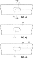
- Figure 4A is an exemplary partial axial cross-sectional view of the respective distal ends of an exhaust lumen 420 and inflation lumen 425 coinciding with the balloon 415, wherein the balloon is shown in a deflated (non-inflated) state.
- a localized fluid communication channel, basin or recess 475 is defined in the outer wall of the catheter shaft in a location anywhere in an axial direction that coincides with the balloon (e.g., proximal region of the balloon, mid region of the balloon, distal region of the balloon) so long as the channel is beneath/underneath (coincides with) the balloon 415.
- the localized fluid communication channel 475 may be D-shape, however, other geometric shapes (e.g., circle, oval, etc.) are contemplated. Fluid communication between terminating distal ends of the respective inflation lumen 425 and exhaust/vent lumen 420 occurs within this localized fluid communication channel 475.
- the terminating distal ends of the respective exhaust and inflation lumen extend partially into the localized fluid communication channel 475. Alternatively, the terminating distal ends of the respective exhaust and inflation lumen may coincide with the perimeter or interface of the localized communication channel 475.
- Figure 4C is a radial cross-sectional view through the localized fluid communication channel 475 along lines IV(C) - IV(C) of Figure 4A depicting the side-by-side configuration of the terminating distal ends of the respective inflation and exhaust lumens 425, 420 therein.
- balloon 415 While in a deflated (non-inflated) state, balloon 415 is taut around the outer surface of the catheter shaft, as shown in Figure 4A .
- the residual air advanced through the inflation lumen 425 by the pressurized injected inflation medium is expelled proximally through the exhaust lumen 420 and from the catheter, without inflating the balloon 415.
- FIG. 4D-4F Alternative arrangements or configurations of the terminating distal ends of the respective exhaust and inflation lumen within the localized fluid communication channel 475 radially outward from the main/guidewire lumen 423 are depicted in the different radial cross-sectional views in Figure 4D-4F .
- inflation lumen 425 and exhaust lumen 420 are side-by-side in physical contact with one another and equal both in inner and outer diameters.
- Figure 4E illustrates again a side-by-side arrangement with the two lumens in physical contact with one another within the localized fluid communication channel 475, however, the lumen differ in both inner and outer diameters.
- the outer diameter of inflation lumen 425 is smaller than the outer diameter of the exhaust lumen 420, but the inner diameter of the inflation lumen 425 is larger than the inner diameter of the exhaust lumen 420.
- the inner diameter of the inflation lumen is greater than the inner diameter of the exhaust lumen since the exhaust lumen merely functions to exhaust the residual air.
- the inflation and exhaust lumens 425, 420 again are disposed side-by-side in physical contact with one another within the localized fluid communication channel 475.
- the outer diameters of the inflation and exhaust lumen are equal in diameter, while the inner diameter of the inflation lumen 425 is greater than that of the exhaust lumen 420. Any combination or permutation of these arrangements of the exhaust and inflation lumens within the channel as well as the sizes of the inner and outer diameters of each lumen is within the scope of the invention.
- Figure 4G is a top view of a partial distal section of still another configuration of the present inventive balloon catheter having a single localized fluid communication channel defined in the shaft in which distal terminating ends of respective exhaust and inflation lumen coincide within the single localized fluid communication channel.
- a surface profile 480 Disposed about a portion of the outer perimeter of the catheter shaft is a surface profile 480 that coincides with the localized fluid communication channel 475 to promote the flow of fluid from the inflation lumen 425 to the exhaust lumen 420.
- the surface profile 480 is a mesh made of polymeric, metal and/or other material wrapped about the outer surface of the catheter shaft.
- the balloon extends axially so as to completely cover or enclose the surface profile 480.
- a radial cross-sectional profile through the single localized fluid communication channel 475 would be similar to that illustrated in Figure 4C , although different arrangements such as those shown in Figures 4D-4F are possible, as desired.
- Figure 4H is a top view of still another configuration in which the terminating distal end of the inflation lumen 425 coincides with a first localized fluid communication channel 475', while the terminating distal end of the exhaust lumen 420 coincides with a second localized fluid communication channel 475" displaced axially apart from the first localized fluid communication channel 475'.
- the surface profile 480 coincides with both the first and second localized fluid communication channels 475', 475".
- the surface profile 480 promotes fluid communication between inflation and exhaust lumens which is particularly applicable in this arrangement wherein the first and second localized fluid communication channels 475', 475" are displaced axially from one another along the catheter shaft.
- a top view of a section of the catheter shaft (without the balloon) shown in Figures 4I & 4J shows a first localized fluid communication channel as a punched hole (e.g., oval, circle, etc.) defined in an outer surface of the catheter shaft.
- the terminating distal end of the inflation lumen 425 extends partially into the punched hole 475 in Figure 4I , whereas in Figure 4J the terminating distal end of the inflation lumen 425 is aligned with the interface of the punched hole 475, that is, the terminating distal end of the inflation lumen does not extend into the punched hole.
- a radial cross-sectional view through the first localized fluid communication channel 475 of Figure 4I along lines IV(K)-IV(K) is shown in Figure 4K .
- the position of the inflation lumen 425 within the first localized fluid communication channel 475 in Figure 4K is to the left; however, the position may be selected, as desired, anywhere within the first localized fluid communication channel 475 (e.g., midway within the channel, to the right within the channel, etc.).
- terminating distal ends of respective inflation and exhaust lumens may be aligned with (coincide with) an interface of a single punched hole defined in the outer surface of the catheter shaft serving as the single localized fluid communication channel, as shown in Figure 4L .
- Figure 5 shows the present inventive balloon catheter 500 with the balloon 515 in an inflated state at a target site in an artery 550.
- Syringe 536 or other injection device is connected to the inflation port 535 in Figure 5 to introduce inflation medium (e.g., 50/50 contrast/saline solution) into the inflation lumen.
- inflation medium e.g., 50/50 contrast/saline solution
- a one-way or manual valve 545 is connected to the exhaust port 537 to control the purging of residual air from the catheter.
- the main/guidewire port or opening 540 is also provided in the hub 530 for receiving a guidewire 90 therein.
- Figure 6A is a partial axial cross-sectional view of the distal end of another exemplary configuration of a balloon catheter 600 in accordance with the present invention, wherein the balloon 615 is in a deflated (non-inflated) state.
- the inflation and exhaust lumens 625, 620 are two separate channels or passageways that extend side-by-side axially in the catheter shaft or body.
- the inflation lumen 625 terminates in at least one inlet port, opening or channel 630 (two being illustrated in Figure 6A ) defined in the outer surface anywhere along the catheter shaft and in fluid communication with the balloon 615 through which the inflation medium passes. Whereas, the residual air is exhausted through an outlet port, opening or channel 635 and into the exhaust lumen 620 defined in the catheter shaft.
- a reinforcing member preferably a metal wire, preferably a 0.001" - 0.003" stainless steel wire such as SS304 grade, made into a coil, braid or both may be provided along a portion of the catheter shaft between the main lumen 623 and the inflation lumen 625 to enhance the stiffness of the distal region of the catheter to aid during navigation of the vessel.
- the reinforcing member is preferably embedded in a soft, flexible polymeric material to prevent the catheter lumen from ovalling, prolapsing and kinking.
- the reinforcing member is a braid 640 disposed about a proximal region of the catheter shaft followed distally thereafter by a coil 640' disposed along a distal region of the catheter shaft.
- a braid or coil alone may serve as the reinforcing member.
- an inner liner preferably made of polytetrafluoroethylene (PTFE)
- PTFE polytetrafluoroethylene
- a reinforcing inner sheath or sleeve 645 may be provided between the main lumen 623 and the inflation lumen 625, radially inward of the reinforcing member.
- inlet opening 630 is disposed distally in an axial direction relative to that of the outlet opening 635.
- the inflation lumen 625 is concentrically (coaxially) arranged, while the exhaust lumen 620 is eccentrically arranged, relative to the main lumen 623.
- Figure 6C depicts the catheter 600 while the balloon 615 is in an inflated state with the inlet and outlet openings 630, 635, respectively, in fluid communication with the balloon 615.
- a top view ( Figure 6D ) of the catheter shaft without the balloon shows the arrangement of the inlet and outlet openings 630, 635.
- any number of one or more inlet ports and one or more outlet ports may be varied, as desired, along with the arrangement of those ports along the catheter shaft.
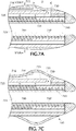
- FIG 7A is a partial longitudinal cross-sectional view of the distal end of yet another exemplary configuration of the balloon catheter 700 in accordance with the present invention.
- the inflation lumen 725 is disposed radially outward of the main lumen 723 between the concentric shafts (see Figure 7B ).
- An exhaust lumen 720 is created by bonding, welding, mounting or attaching a thin polymer jacket 716 about the outer surface of the catheter shaft creating a passageway or space therebetween that serves as an exhaust lumen 720.
- Inflation medium travels though the inflation lumen 725, out from the inlet opening 730, and into the balloon 715.
- the axial distance D between the inlet port 730 and the outlet port 735 is preferably minimized to assist in communication of expelled residual air between the inflation and exhaust lumen.
- the relatively large exhaust lumen created by the relatively thin polymer jacket mounted to the outer surface of the outer shaft provides the benefit of reduced prepping time and superior deflation times when the exhaust lumen is opened.
- reinforcing structures e.g., a braid 740, coil 740' and/or inner sheath 745 may be employed to provide enhanced stiffness to the catheter.
- Figure 8A is a partial axial cross-sectional view of the distal end of still another exemplary configuration of the balloon catheter 800 in accordance with the present invention.
- This design is similar to that of Figure 6A in that the inflation lumen 825 is concentrically arranged relative to the main lumen 823.
- the axially extending exhaust lumen 820 is an independent isolated lumen disposed entirely within the inflation lumen 825 between the inner and outer shafts of the catheter body, as shown in Figure 8B .
- the inlet opening 830 is in fluid communication with the balloon 815, while the outlet opening 835 is defined in the outer shaft providing a direct communication between the balloon 815 and exhaust lumen 820.
- An enlarged inner diameter is a benefit of this balloon catheter design able to accommodate a wide range of ancillary devices having larger outer diameters.
- reinforcing structures e.g., a braid 840, a coil 840' and/or an inner sheath 845 may be employed to provide enhanced stiffness to the catheter.
- FIG. 9A Yet another exemplary configuration of the balloon catheter 900 in accordance with the present invention is represented by the partial axial cross-sectional view of the distal end of the catheter in Figure 9A .
- the inflation lumen 925 is concentrically arranged relative to the main lumen 923, while each of the two exhaust lumens 920 are eccentrically arranged relative to the main lumen 923.
- the inflation lumen was disposed between the inner and outer shafts comprising the catheter body.
- the exhaust lumen 920 is disposed within the inner catheter shaft radially between the main lumen 923 and the inflation lumen 925.
- Figure 9B is a radial cross-sectional view of the catheter along lines IX(B) - IX(B) in which the two exhaust lumens 920 disposed within the inner shaft and radially inward of the inflation lumen 925 is clearly illustrated.
- Figure 9C depicts the catheter of Figure 9A while in an inflated state.
- the inflation lumen is concentric (coaxial), while the exhaust lumen is eccentric, with respect to the main/guidewire lumen.
- Figure 10A is a perspective view of yet another configuration of the present inventive balloon guide catheter having dual lumen (one inflation lumen 1025 and one exhaust lumen 1020) defined in the outer wall of the catheter shaft, aside from the main lumen 1023. Terminating distal ends of the respective inflation and exhaust lumens 1025, 1023 coincide with a localized fluid communication channel, recess or basin 1075.
- the localized fluid communication channel 1075 is where the terminating distal ends of the respective inflation and exhaust lumens are in fluid communication with one another.
- a balloon, not illustrated in Figure 10A is assembled taut or snug about the outer surface of the distal region of the catheter shaft covering the localized fluid communication channel 1075.
- a proximal hub 1030 is connected to the proximal end of the balloon guide catheter. Hub 1030 includes a main/guidewire port 1040, an inflation port 1035 and an exhaust/vent port 1045. A valve 1095 is disposed at the exhaust port 1045.
- FIG 11A is a cross-sectional axial view of the hub 1030 in Figure 10A , wherein a 3-way valve 1095 is oriented or positioned for inflation of the balloon with an inflation medium (e.g., 50/50 contrast/saline solution) injected into the inflation port 1040 (via a syringe 536 similar to that shown in Figure 5 ).
- Inflation medium injected into the inflation port 1040 enters an inflation opening 1026 in the outer wall of the catheter shaft and fills the inflation lumen 1025.
- the inflation medium reaching the localized fluid communication channel it enters the exhaust lumen 1020 and travels proximally therethrough exiting from the vent opening 1027 and into the hub 1030.
- Valve 1095 disposed distally of the exhaust port 1045 is oriented or positioned in Figure 11A in an open state allowing the flow of residual air therethrough which then passes out of the exhaust port 1045 via a microporous membrane or filter 1021. Pores or openings of the microporous membrane or filter 1021 are sized to permit the passage therethrough of residual air, while prohibiting or preventing passage therethrough of the inflation medium.
- any additional flow of the inflation medium or increase in pressure applied by the syringe causes the balloon to inflate. Flow rates of the inflation medium are maintained so that full venting of residual air occurs without sufficient pressure built-up or generated in the catheter to initiate inflation of the balloon.
- the localized fluid communication channel 1075 underneath the balloon is designed so that both lumens (the exhaust lumen 1020 and the inflation lumen 1025) communicate allowing residual air and inflation medium to flow out from the terminating distal end of the inflation lumen and into the terminating distal end of the exhaust lumen.
- Deflation of the balloon is achieved by attaching a vacuum (e.g., syringe) to the inflation port 1040 creating a negative pressure within the catheter.
- a vacuum e.g., syringe
- valve 1095 is oriented to close off flow to the exhaust port 1045.
- a vacuum or suction e.g., syringe
- the inflation medium exhausted from the exhaust lumen is redirected into the bridge fluid communication channel 1090, combining with the inflation medium vented through the inflation lumen and out from the inflation port 1040.
- This unique hub configuration and, in particular, the orientation or positioning of the valve during deflation to close off the exhaust port 1045, upon application of a vacuum to the inflation port provides for the removal of inflation medium simultaneously through both inflation and exhaust lumens thereby optimizing deflation of the balloon.
- the configuration of the hub 1030 is optimized by minimizing its overall axial length in order to minimize cost of manufacture as well as minimize the unusable length of hub that other catheters go through. It is also contemplated to replace the 3-way manual valve 1095 with a spring-loaded or ball valve that is automatically actuated upon the introduction of a suction or vacuum applied to the inflation port 1040.
- the present inventive closed loop proximal venting system has several advantages. Since the residual air is vented in a proximal direction preparation of the device by the interventionalist may occur while the device is in the patient. Another benefit of the present inventive closed loop proximal design is that the inflation medium automatically expels the residual air/gas through the microporous membrane and out the exhaust lumen while the inflation medium is prevented from passing through the microporous membrane thereby causing the balloon to inflate and expand. Accordingly, the need for a valve or other mechanical device for causing the balloon to inflate once the residual air has been purged has been eliminated in accordance with the present invention.
Landscapes
- Health & Medical Sciences (AREA)
- Life Sciences & Earth Sciences (AREA)
- Heart & Thoracic Surgery (AREA)
- General Health & Medical Sciences (AREA)
- Public Health (AREA)
- Engineering & Computer Science (AREA)
- Biomedical Technology (AREA)
- Animal Behavior & Ethology (AREA)
- Veterinary Medicine (AREA)
- Pulmonology (AREA)
- Anesthesiology (AREA)
- Hematology (AREA)
- Biophysics (AREA)
- Surgery (AREA)
- Child & Adolescent Psychology (AREA)
- Vascular Medicine (AREA)
- Nuclear Medicine, Radiotherapy & Molecular Imaging (AREA)
- Medical Informatics (AREA)
- Molecular Biology (AREA)
- Reproductive Health (AREA)
- Orthopedic Medicine & Surgery (AREA)
- Physics & Mathematics (AREA)
- Geometry (AREA)
- Media Introduction/Drainage Providing Device (AREA)
Applications Claiming Priority (5)
| Application Number | Priority Date | Filing Date | Title |
|---|---|---|---|
| US201962845711P | 2019-05-09 | 2019-05-09 | |
| US201962845747P | 2019-05-09 | 2019-05-09 | |
| US201962845683P | 2019-05-09 | 2019-05-09 | |
| US201962845699P | 2019-05-09 | 2019-05-09 | |
| US16/601,221 US11607531B2 (en) | 2019-05-09 | 2019-10-14 | Balloon catheter with venting of residual air in a proximal direction |
Publications (4)
| Publication Number | Publication Date |
|---|---|
| EP3736013A2 true EP3736013A2 (de) | 2020-11-11 |
| EP3736013A3 EP3736013A3 (de) | 2020-11-18 |
| EP3736013B1 EP3736013B1 (de) | 2025-06-11 |
| EP3736013C0 EP3736013C0 (de) | 2025-06-11 |
Family
ID=70616969
Family Applications (1)
| Application Number | Title | Priority Date | Filing Date |
|---|---|---|---|
| EP20173467.0A Active EP3736013B1 (de) | 2019-05-09 | 2020-05-07 | Ballonkatheter mit entlüftung von restluft in proximaler richtung |
Country Status (6)
| Country | Link |
|---|---|
| US (2) | US11607531B2 (de) |
| EP (1) | EP3736013B1 (de) |
| JP (1) | JP7605394B2 (de) |
| KR (1) | KR20200130665A (de) |
| CN (1) | CN111956935B (de) |
| ES (1) | ES3034791T3 (de) |
Families Citing this family (9)
| Publication number | Priority date | Publication date | Assignee | Title |
|---|---|---|---|---|
| US20200107849A1 (en) * | 2018-10-08 | 2020-04-09 | Chris Salvino | Actuating scalpel device |
| US12285182B2 (en) | 2018-10-10 | 2025-04-29 | Innova Vascular, Inc. | Devices and methods for removing an embolus |
| US11241561B2 (en) * | 2019-11-21 | 2022-02-08 | Stryker Corporation | Balloon catheter with porous outer member for air purging |
| US11197684B1 (en) | 2021-03-04 | 2021-12-14 | Nventric Corporation | Thrombectomy device and method |
| CN114288529A (zh) * | 2022-01-24 | 2022-04-08 | 茵络(无锡)医疗器械有限公司 | 一种球囊扩张装置及其使用方法 |
| CN116570822A (zh) * | 2022-02-01 | 2023-08-11 | 艾柯医疗器械(北京)股份有限公司 | 多腔球囊导引导管装置和使用方法 |
| CN115120298A (zh) * | 2022-08-02 | 2022-09-30 | 为泰医疗器械(深圳)有限公司 | 双腔封堵球囊导管及其使用方法 |
| US12114880B1 (en) | 2023-08-03 | 2024-10-15 | Nventric Corporation | Thrombectomy device having open frame cell ring |
| CN117883684B (zh) * | 2023-12-28 | 2025-09-12 | 天津市环湖医院(天津市神经外科研究所、天津市脑系科中心医院) | 球囊导管 |
Family Cites Families (190)
| Publication number | Priority date | Publication date | Assignee | Title |
|---|---|---|---|---|
| GB1318278A (en) * | 1969-09-23 | 1973-05-23 | Sheridan D S | Manufacture of medico-surgical tubes |
| US4188954A (en) | 1976-08-05 | 1980-02-19 | The Kendall Company | Catheter with improved balloon assembly |
| US4323071A (en) | 1978-04-24 | 1982-04-06 | Advanced Catheter Systems, Inc. | Vascular guiding catheter assembly and vascular dilating catheter assembly and a combination thereof and methods of making the same |
| JPS59166163A (ja) * | 1983-03-14 | 1984-09-19 | テルモ株式会社 | バル−ンカテ−テル |
| JPS59177064A (ja) * | 1983-03-29 | 1984-10-06 | テルモ株式会社 | バル−ンカテ−テル |
| US4684363A (en) | 1984-10-31 | 1987-08-04 | American Hospital Supply Corporation | Rapidly inflatable balloon catheter and method |
| US4715378A (en) | 1986-07-28 | 1987-12-29 | Mansfield Scientific, Inc. | Balloon catheter |
| JPS6395065A (ja) | 1986-10-09 | 1988-04-26 | オリンパス光学工業株式会社 | バル−ンカテ−テル |
| JPS63158064A (ja) * | 1986-12-23 | 1988-07-01 | テルモ株式会社 | 血管拡張カテ−テル |
| US4821722A (en) | 1987-01-06 | 1989-04-18 | Advanced Cardiovascular Systems, Inc. | Self-venting balloon dilatation catheter and method |
| US4753238A (en) * | 1987-01-06 | 1988-06-28 | Advanced Cardiovascular Systems, Inc. | Proximal manifold and adapter |
| US5256143A (en) | 1987-01-06 | 1993-10-26 | Advanced Cardiovascular Systems, Inc. | Self-venting balloon dilatation catheter |
| US4793351A (en) * | 1987-06-15 | 1988-12-27 | Mansfield Scientific, Inc. | Multi-lumen balloon catheter |
| US4811737A (en) | 1987-11-16 | 1989-03-14 | Schneider-Shiley (Usa) Inc. | Self-purging balloon catheter |
| US5035705A (en) | 1989-01-13 | 1991-07-30 | Scimed Life Systems, Inc. | Method of purging a balloon catheter |
| US5100385A (en) | 1989-01-27 | 1992-03-31 | C. R. Bard, Inc. | Fast purge balloon dilatation catheter |
| US5135486A (en) | 1990-08-31 | 1992-08-04 | Endosonics Corporation | Self-venting balloon dilitation catheter |
| US5176698A (en) | 1991-01-09 | 1993-01-05 | Scimed Life Systems, Inc. | Vented dilatation cathether and method for venting |
| US5224933A (en) | 1992-03-23 | 1993-07-06 | C. R. Bard, Inc. | Catheter purge device |
| US5800421A (en) | 1996-06-12 | 1998-09-01 | Lemelson; Jerome H. | Medical devices using electrosensitive gels |
| US6869431B2 (en) | 1997-07-08 | 2005-03-22 | Atrionix, Inc. | Medical device with sensor cooperating with expandable member |
| US6010521A (en) | 1997-11-25 | 2000-01-04 | Advanced Cardiovasular Systems, Inc. | Catheter member with bondable layer |
| NL1008051C2 (nl) | 1998-01-16 | 1999-07-19 | Cordis Europ | Ballonkatheter. |
| US6517515B1 (en) | 1998-03-04 | 2003-02-11 | Scimed Life Systems, Inc. | Catheter having variable size guide wire lumen |
| US6960222B2 (en) | 1998-03-13 | 2005-11-01 | Gore Enterprise Holdins, Inc. | Catheter having a funnel-shaped occlusion balloon of uniform thickness and methods of manufacture |
| US6709429B1 (en) | 2000-01-19 | 2004-03-23 | Scimed Life Systems, Inc. | Intravascular catheter with multiple axial fibers |
| US6464625B2 (en) | 1999-06-23 | 2002-10-15 | Robert A. Ganz | Therapeutic method and apparatus for debilitating or killing microorganisms within the body |
| US6102931A (en) | 1999-08-09 | 2000-08-15 | Embol-X, Inc. | Intravascular device for venting an inflatable chamber |
| US6994687B1 (en) | 2000-01-19 | 2006-02-07 | Cordis Neurovascular, Inc. | Inflatable balloon catheter with purge mechanism and method |
| GB0011053D0 (en) | 2000-05-09 | 2000-06-28 | Hudson John O | Medical device and use thereof |
| US6786887B2 (en) | 2001-01-26 | 2004-09-07 | Scimed Life Systems, Inc. | Intravascular occlusion balloon catheter |
| US6673001B2 (en) | 2001-03-29 | 2004-01-06 | Zsolt Toth | Compact apparatus and system for creating and dispensing cushioning dunnage |
| US8252040B2 (en) | 2001-07-20 | 2012-08-28 | Microvention, Inc. | Aneurysm treatment device and method of use |
| US8715312B2 (en) | 2001-07-20 | 2014-05-06 | Microvention, Inc. | Aneurysm treatment device and method of use |
| US6923787B2 (en) | 2001-12-20 | 2005-08-02 | Scimed Life Systems, Inc. | Catheter having an improved balloon-to-catheter bond |
| US6953431B2 (en) | 2002-04-11 | 2005-10-11 | University Of South Florida | Eccentric dilation balloons for use with endoscopes |
| US7338511B2 (en) | 2002-05-24 | 2008-03-04 | Boston Scientific-Scimed, Inc. | Solid embolic material with variable expansion |
| WO2004026371A2 (en) | 2002-09-20 | 2004-04-01 | Flowmedica, Inc. | Method and apparatus for selective drug infusion via an intraaortic flow diverter delivery catheter |
| US20040260329A1 (en) | 2003-06-19 | 2004-12-23 | Richard Gribbons | Catheter and guide wire exchange system with decoupled guide member |
| US7371228B2 (en) | 2003-09-19 | 2008-05-13 | Medtronic Vascular, Inc. | Delivery of therapeutics to treat aneurysms |
| US20050070881A1 (en) | 2003-09-26 | 2005-03-31 | Richard Gribbons | Transition section for a catheter |
| US20050124932A1 (en) | 2003-12-05 | 2005-06-09 | Kimberly-Clark Worldwide, Inc. | Venting catheter |
| US20080147048A1 (en) | 2004-01-09 | 2008-06-19 | Deutsch Harvey L | Drain with Occlusion Removing Structure |
| US7641631B2 (en) | 2004-02-17 | 2010-01-05 | Scimed Life Systems, Inc. | Dilatation balloon having a valved opening and related catheters and methods |
| US9308382B2 (en) | 2004-06-10 | 2016-04-12 | Medtronic Urinary Solutions, Inc. | Implantable pulse generator systems and methods for providing functional and/or therapeutic stimulation of muscles and/or nerves and/or central nervous system tissue |
| US9655633B2 (en) | 2004-09-10 | 2017-05-23 | Penumbra, Inc. | System and method for treating ischemic stroke |
| US20060089637A1 (en) | 2004-10-14 | 2006-04-27 | Werneth Randell L | Ablation catheter |
| US8562672B2 (en) | 2004-11-19 | 2013-10-22 | Medtronic, Inc. | Apparatus for treatment of cardiac valves and method of its manufacture |
| US7678075B2 (en) | 2004-12-30 | 2010-03-16 | Advanced Cardiovascular Systems, Inc. | Infusion catheter and use thereof |
| US9636115B2 (en) | 2005-06-14 | 2017-05-02 | Stryker Corporation | Vaso-occlusive delivery device with kink resistant, flexible distal end |
| EP2759276A1 (de) | 2005-06-20 | 2014-07-30 | Medtronic Ablation Frontiers LLC | Ablationskatheter |
| US7500982B2 (en) | 2005-06-22 | 2009-03-10 | Futurematrix Interventional, Inc. | Balloon dilation catheter having transition from coaxial lumens to non-coaxial multiple lumens |
| CA2630021C (en) | 2005-11-17 | 2013-08-13 | Microvention, Inc. | Three-dimensional complex coil |
| US9757260B2 (en) | 2006-03-30 | 2017-09-12 | Medtronic Vascular, Inc. | Prosthesis with guide lumen |
| US9615832B2 (en) | 2006-04-07 | 2017-04-11 | Penumbra, Inc. | Aneurysm occlusion system and method |
| WO2007139799A2 (en) | 2006-05-24 | 2007-12-06 | Mayo Foundation For Medical Education And Research | Devices and methods for crossing chronic total occlusions |
| US8377091B2 (en) | 2006-06-15 | 2013-02-19 | Microvention, Inc. | Embolization device constructed from expansile polymer |
| US8066670B2 (en) * | 2006-11-06 | 2011-11-29 | Becton, Dickinson And Company | Vascular access device septum venting |
| US11660420B2 (en) | 2018-09-17 | 2023-05-30 | Seigla Medical, Inc. | Catheters and related devices and methods of manufacture |
| AU2008345590B2 (en) | 2007-12-21 | 2014-10-30 | Microvention, Inc. | Hydrogel filaments for biomedical uses |
| US8974518B2 (en) | 2008-03-25 | 2015-03-10 | Medtronic Vascular, Inc. | Eversible branch stent-graft and deployment method |
| US9572982B2 (en) | 2008-04-30 | 2017-02-21 | Medtronic, Inc. | Techniques for placing medical leads for electrical stimulation of nerve tissue |
| US8070694B2 (en) | 2008-07-14 | 2011-12-06 | Medtronic Vascular, Inc. | Fiber based medical devices and aspiration catheters |
| US8333796B2 (en) | 2008-07-15 | 2012-12-18 | Penumbra, Inc. | Embolic coil implant system and implantation method |
| US8721714B2 (en) | 2008-09-17 | 2014-05-13 | Medtronic Corevalve Llc | Delivery system for deployment of medical devices |
| US8021420B2 (en) | 2009-03-12 | 2011-09-20 | Medtronic Vascular, Inc. | Prosthetic valve delivery system |
| KR101719831B1 (ko) | 2009-04-15 | 2017-03-24 | 마이크로벤션, 인코포레이티드 | 임플란트 전달 시스템 |
| US8298218B2 (en) | 2009-07-29 | 2012-10-30 | Medtronic Cryocath Lp | Compliant balloon |
| WO2011038017A1 (en) | 2009-09-22 | 2011-03-31 | Penumbra, Inc. | Manual actuation system for deployment of implant |
| BR112012025969B1 (pt) | 2010-04-14 | 2021-01-05 | Microvention, Inc. | dispositivo de fornecimento de implante |
| US8764811B2 (en) | 2010-04-20 | 2014-07-01 | Medtronic Vascular, Inc. | Controlled tip release stent graft delivery system and method |
| US9155869B2 (en) | 2010-04-30 | 2015-10-13 | Abbott Cardiovascular Systems Inc. | Catheter having inflation and deflation lumen useful for preventing or reducing reperfusion injury |
| US8876878B2 (en) | 2010-07-23 | 2014-11-04 | Medtronic, Inc. | Attachment mechanism for stent release |
| US8616040B2 (en) | 2010-09-17 | 2013-12-31 | Medtronic Vascular, Inc. | Method of forming a drug-eluting medical device |
| US8956383B2 (en) | 2010-12-03 | 2015-02-17 | ArgioDynamics, Inc. | Devices and methods for removing clots |
| WO2012088162A1 (en) | 2010-12-20 | 2012-06-28 | Microvention, Inc. | Polymer stents and methods of manufacture |
| US8721588B2 (en) | 2011-04-15 | 2014-05-13 | DePuy Synthes Products, LLC | Noncircular inner lumen guiding catheter with assisted variable support |
| US9486604B2 (en) | 2011-05-12 | 2016-11-08 | Medtronic, Inc. | Packaging and preparation tray for a delivery system |
| WO2012158668A1 (en) | 2011-05-17 | 2012-11-22 | Stryker Corporation | Method of fabricating an implantable medical device that includes one or more thin film polymer support layers |
| WO2012162183A1 (en) | 2011-05-20 | 2012-11-29 | Boston Scientific Scimed, Inc. | Balloon catheter with improved pushability |
| WO2012166467A1 (en) | 2011-05-27 | 2012-12-06 | Stryker Corporation | Assembly for percutaneously inserting an implantable medical device, steering the device to a target location and deploying the device |
| EP2572749B1 (de) | 2011-09-23 | 2022-04-27 | Covidien LP | Ballonführungskatheter für distalen Zugang |
| US9750565B2 (en) | 2011-09-30 | 2017-09-05 | Medtronic Advanced Energy Llc | Electrosurgical balloons |
| EP3156006B1 (de) | 2012-03-16 | 2022-05-18 | Terumo Corporation | Stent und stentfreisetzungssystem |
| US9717421B2 (en) | 2012-03-26 | 2017-08-01 | Medtronic, Inc. | Implantable medical device delivery catheter with tether |
| US9833625B2 (en) | 2012-03-26 | 2017-12-05 | Medtronic, Inc. | Implantable medical device delivery with inner and outer sheaths |
| US9242290B2 (en) | 2012-04-03 | 2016-01-26 | Medtronic Vascular, Inc. | Method and apparatus for creating formed elements used to make wound stents |
| EP2841142A4 (de) | 2012-04-24 | 2015-12-09 | Mayser Llc | Ballonkatheter mit dehnungsventil und verfahren zur herstellung und verwendung davon |
| US9549832B2 (en) | 2012-04-26 | 2017-01-24 | Medtronic Vascular, Inc. | Apparatus and methods for filling a drug eluting medical device via capillary action |
| US9700399B2 (en) | 2012-04-26 | 2017-07-11 | Medtronic Vascular, Inc. | Stopper to prevent graft material slippage in a closed web stent-graft |
| US9241752B2 (en) | 2012-04-27 | 2016-01-26 | Medtronic Ardian Luxembourg S.A.R.L. | Shafts with pressure relief in cryotherapeutic catheters and associated devices, systems, and methods |
| US9445828B2 (en) | 2012-07-05 | 2016-09-20 | Cognition Medical Corp. | Methods, devices, and systems for postconditioning with clot removal |
| US9149190B2 (en) | 2012-07-17 | 2015-10-06 | Stryker Corporation | Notification system of deviation from predefined conditions |
| WO2014028528A1 (en) | 2012-08-13 | 2014-02-20 | Microvention, Inc. | Shaped removal device |
| US9993628B2 (en) | 2012-08-22 | 2018-06-12 | Volcano Corporation | Balloon catheter junction |
| US9504476B2 (en) | 2012-10-01 | 2016-11-29 | Microvention, Inc. | Catheter markers |
| CN108992204B (zh) * | 2012-10-01 | 2021-11-23 | C·R·巴德公司 | 具有多个充注内腔的球囊导管和相关方法 |
| JP6385937B2 (ja) | 2012-10-15 | 2018-09-05 | マイクロベンション インコーポレイテッドMicrovention, Inc. | ポリマーの治療用組成物 |
| US9539022B2 (en) | 2012-11-28 | 2017-01-10 | Microvention, Inc. | Matter conveyance system |
| WO2014089390A1 (en) | 2012-12-07 | 2014-06-12 | Medtronic, Inc. | Minimally invasive implantable neurostimulation system |
| JP5242848B1 (ja) | 2012-12-27 | 2013-07-24 | 富士システムズ株式会社 | パージ孔付きバルーンカテーテル |
| JP6149431B2 (ja) | 2013-03-08 | 2017-06-21 | 住友ベークライト株式会社 | 医療用機器、カテーテルおよび医療用機器の製造方法 |
| US20140257359A1 (en) | 2013-03-11 | 2014-09-11 | St. Jude Medical Puerto Rico Llc | Temporary sealing device with blood flashback for vessel location |
| US9539382B2 (en) | 2013-03-12 | 2017-01-10 | Medtronic, Inc. | Stepped catheters with flow restrictors and infusion systems using the same |
| WO2014150824A1 (en) | 2013-03-14 | 2014-09-25 | Stryker Corporation | Vaso-occlusive device delivery system |
| CN105228534B (zh) | 2013-03-14 | 2018-03-30 | 斯瑞克公司 | 血管闭塞装置输送系统 |
| WO2014159606A1 (en) | 2013-03-14 | 2014-10-02 | Stryker Corporation | Vaso-occlusive device delivery system |
| US20140276028A1 (en) | 2013-03-15 | 2014-09-18 | Volcano Corporation | Integrated Therapeutic Imaging Catheter and Methods |
| BR112015023602A2 (pt) | 2013-03-15 | 2017-07-18 | Microvention Inc | dispositivo de proteção embólica |
| US9833252B2 (en) | 2013-03-15 | 2017-12-05 | Microvention, Inc. | Multi-component obstruction removal system and method |
| US9398966B2 (en) | 2013-03-15 | 2016-07-26 | Medtronic Vascular, Inc. | Welded stent and stent delivery system |
| US9662425B2 (en) | 2013-04-22 | 2017-05-30 | Stryker European Holdings I, Llc | Method for drug loading hydroxyapatite coated implant surfaces |
| US9445928B2 (en) | 2013-05-30 | 2016-09-20 | Medtronic Vascular, Inc. | Delivery system having a single handed deployment handle for a retractable outer sheath |
| US10086173B2 (en) | 2013-07-25 | 2018-10-02 | Merit Medical Systems, Inc. | Balloon catheter systems and methods |
| US9901716B2 (en) | 2013-09-10 | 2018-02-27 | Cook Medical Technologies Llc | Tipless balloon catheter with stiffening member through balloon |
| US9675782B2 (en) | 2013-10-10 | 2017-06-13 | Medtronic Vascular, Inc. | Catheter pull wire actuation mechanism |
| US9439827B2 (en) | 2013-10-25 | 2016-09-13 | Medtronic Vascular, Inc. | Tissue compression device with pressure indicator |
| KR102211335B1 (ko) | 2013-12-20 | 2021-02-03 | 마이크로벤션, 인코포레이티드 | 장치 전달 시스템 |
| EP3082939B1 (de) | 2013-12-20 | 2020-12-02 | MicroVention, Inc. | Ausgabeadapter |
| WO2015095587A1 (en) | 2013-12-20 | 2015-06-25 | Boston Scientific Scimed, Inc. | Integrated catheter system |
| US9855089B2 (en) | 2014-03-21 | 2018-01-02 | Medtronic Cryocath Lp | Shape changing ablation balloon |
| CN106163459B (zh) | 2014-04-08 | 2018-05-29 | 斯瑞克公司 | 植入物递送系统 |
| WO2015167997A1 (en) | 2014-04-30 | 2015-11-05 | Stryker Corporation | Implant delivery system and method of use |
| US9060777B1 (en) | 2014-05-28 | 2015-06-23 | Tw Medical Technologies, Llc | Vaso-occlusive devices and methods of use |
| EP4470485A3 (de) | 2014-06-13 | 2025-02-19 | Neuravi Limited | Vorrichtungen und verfahren zur entfernung von akuten verstopfungen aus blutgefässen |
| US9668898B2 (en) | 2014-07-24 | 2017-06-06 | Medtronic Vascular, Inc. | Stent delivery system having dynamic deployment and methods of manufacturing same |
| US9770577B2 (en) | 2014-09-15 | 2017-09-26 | Medtronic Xomed, Inc. | Pressure relief for a catheter balloon device |
| US9579484B2 (en) | 2014-09-19 | 2017-02-28 | Medtronic Vascular, Inc. | Sterile molded dispenser |
| WO2016081950A1 (en) | 2014-11-21 | 2016-05-26 | Microvention, Inc. | Improved reinforced balloon catheter |
| US9692557B2 (en) | 2015-02-04 | 2017-06-27 | Stryker European Holdings I, Llc | Apparatus and methods for administering treatment within a bodily duct of a patient |
| JP2016168151A (ja) | 2015-03-12 | 2016-09-23 | 株式会社東海メディカルプロダクツ | バルーンカテーテル |
| JP6472536B2 (ja) | 2015-03-19 | 2019-02-20 | プリタイム・メディカル・デバイシーズ・インコーポレイテッドPrytime Medical Devices,Inc. | 低プロファイル閉塞バルーンカテーテル用のシステムおよび方法 |
| US10307168B2 (en) | 2015-08-07 | 2019-06-04 | Terumo Corporation | Complex coil and manufacturing techniques |
| US10154905B2 (en) | 2015-08-07 | 2018-12-18 | Medtronic Vascular, Inc. | System and method for deflecting a delivery catheter |
| US10492938B2 (en) | 2015-08-11 | 2019-12-03 | Terumo Corporation | System and method for implant delivery |
| US10322020B2 (en) | 2015-09-18 | 2019-06-18 | Terumo Corporation | Pushable implant delivery system |
| CN108348323B (zh) | 2015-09-18 | 2021-11-16 | 微仙美国有限公司 | 植入物固位、脱离以及递送系统 |
| WO2017049312A1 (en) | 2015-09-18 | 2017-03-23 | Microvention, Inc. | Releasable delivery system |
| EP3349669B1 (de) | 2015-09-18 | 2020-10-21 | Terumo Corporation | Gefässprothese |
| ES2788738T3 (es) | 2015-09-21 | 2020-10-22 | Stryker Corp | Dispositivos de embolectomía |
| WO2017053287A1 (en) | 2015-09-21 | 2017-03-30 | Stryker Corporation | Embolectomy devices |
| US10172632B2 (en) | 2015-09-22 | 2019-01-08 | Medtronic Vascular, Inc. | Occlusion bypassing apparatus with a re-entry needle and a stabilization tube |
| JP2018529495A (ja) | 2015-09-28 | 2018-10-11 | ストライカー コーポレイションStryker Corporation | 機械的血栓摘出装置および方法 |
| US10327791B2 (en) | 2015-10-07 | 2019-06-25 | Medtronic Vascular, Inc. | Occlusion bypassing apparatus with a re-entry needle and a distal stabilization balloon |
| WO2017062383A1 (en) | 2015-10-07 | 2017-04-13 | Stryker Corporation | Multiple barrel clot removal devices |
| US10786302B2 (en) | 2015-10-09 | 2020-09-29 | Medtronic, Inc. | Method for closure and ablation of atrial appendage |
| US10271873B2 (en) | 2015-10-26 | 2019-04-30 | Medtronic Vascular, Inc. | Sheathless guide catheter assembly |
| WO2017087195A1 (en) | 2015-11-18 | 2017-05-26 | Shockwave Medical, Inc. | Shock wave electrodes |
| US20170147765A1 (en) | 2015-11-19 | 2017-05-25 | Penumbra, Inc. | Systems and methods for treatment of stroke |
| US10631946B2 (en) | 2015-11-30 | 2020-04-28 | Penumbra, Inc. | System for endoscopic intracranial procedures |
| US10369326B2 (en) | 2015-12-09 | 2019-08-06 | Medtronic Vascular, Inc. | Catheter with a lumen shaped as an identification symbol |
| US10500046B2 (en) | 2015-12-14 | 2019-12-10 | Medtronic, Inc. | Delivery system having retractable wires as a coupling mechanism and a deployment mechanism for a self-expanding prosthesis |
| US10159568B2 (en) | 2015-12-14 | 2018-12-25 | Medtronic, Inc. | Delivery system having retractable wires as a coupling mechanism and a deployment mechanism for a self-expanding prosthesis |
| ES2913227T3 (es) | 2015-12-30 | 2022-06-01 | Stryker Corp | Dispositivos embólicos |
| US20170189033A1 (en) | 2016-01-06 | 2017-07-06 | Microvention, Inc. | Occlusive Embolic Coil |
| US10070950B2 (en) | 2016-02-09 | 2018-09-11 | Medtronic Vascular, Inc. | Endoluminal prosthetic assemblies, and associated systems and methods for percutaneous repair of a vascular tissue defect |
| BR122018071070A2 (pt) | 2016-02-10 | 2019-09-10 | Microvention Inc | dispositivos para oclusão vascular |
| AU2017217879B9 (en) | 2016-02-10 | 2021-08-19 | Microvention, Inc. | Intravascular treatment site access |
| US10188500B2 (en) | 2016-02-12 | 2019-01-29 | Medtronic Vascular, Inc. | Stent graft with external scaffolding and method |
| WO2017172735A1 (en) | 2016-03-31 | 2017-10-05 | 1/1Medtronic Vascular Inc. | Endoluminal prosthetic devices having fluid-absorbable compositions for repair of a vascular tissue defect |
| WO2017172451A1 (en) | 2016-03-31 | 2017-10-05 | Medtronic Vascular Inc. | Expandable introducer sheath having a steering mechanism |
| US10695542B2 (en) | 2016-04-04 | 2020-06-30 | Medtronic Vascular, Inc. | Drug coated balloon |
| US10252024B2 (en) | 2016-04-05 | 2019-04-09 | Stryker Corporation | Medical devices and methods of manufacturing same |
| US10441407B2 (en) | 2016-04-12 | 2019-10-15 | Medtronic Vascular, Inc. | Gutter filling stent-graft and method |
| US9987122B2 (en) | 2016-04-13 | 2018-06-05 | Medtronic Vascular, Inc. | Iliac branch device and method |
| CN205649678U (zh) * | 2016-04-15 | 2016-10-19 | 张家庆 | 引流管以及引流装置 |
| US10010403B2 (en) | 2016-04-18 | 2018-07-03 | Medtronic Vascular, Inc. | Stent-graft prosthesis and method of manufacture |
| US20170304097A1 (en) | 2016-04-21 | 2017-10-26 | Medtronic Vascular, Inc. | Stent-graft delivery system having an inner shaft component with a loading pad or covering on a distal segment thereof for stent retention |
| US10940294B2 (en) | 2016-04-25 | 2021-03-09 | Medtronic Vascular, Inc. | Balloon catheter including a drug delivery sheath |
| CN109414272B (zh) | 2016-04-25 | 2021-09-28 | 斯瑞克公司 | 翻转机械血栓切除装置及在血管系统中使用的方法 |
| CN113576607B (zh) | 2016-04-25 | 2024-11-29 | 斯瑞克公司 | 预加载的翻转牵引器血栓切除装置及方法 |
| ES2859656T3 (es) | 2016-04-25 | 2021-10-04 | Stryker Corp | Aparatos de trombectomía antiatascamiento y macerante |
| US10517711B2 (en) | 2016-04-25 | 2019-12-31 | Medtronic Vascular, Inc. | Dissection prosthesis system and method |
| US10406011B2 (en) | 2016-04-28 | 2019-09-10 | Medtronic Vascular, Inc. | Implantable medical device delivery system |
| US11147952B2 (en) | 2016-04-28 | 2021-10-19 | Medtronic Vascular, Inc. | Drug coated inflatable balloon having a thermal dependent release layer |
| US10191615B2 (en) | 2016-04-28 | 2019-01-29 | Medtronic Navigation, Inc. | Method and apparatus for image-based navigation |
| MA44884A (fr) | 2016-05-06 | 2019-03-13 | Mayo Found Medical Education & Res | Dispositifs et procédés de thrombectomie de l'artère carotide interne |
| US10292844B2 (en) | 2016-05-17 | 2019-05-21 | Medtronic Vascular, Inc. | Method for compressing a stented prosthesis |
| EP3463543B1 (de) | 2016-06-01 | 2021-04-14 | Microvention, Inc. | Verbesserter verstärkter ballonkatheter |
| CN113440223B (zh) | 2016-06-03 | 2024-08-06 | 斯瑞克公司 | 翻转血栓切除装置 |
| US10576254B2 (en) | 2016-08-05 | 2020-03-03 | Covidien Lp | Medical balloon having a plurality of structural layers |
| AU2017312421A1 (en) | 2016-08-17 | 2019-03-07 | Neuravi Limited | A clot retrieval system for removing occlusive clot from a blood vessel |
| CN107875500A (zh) * | 2016-09-27 | 2018-04-06 | 先健科技(深圳)有限公司 | 球囊导管 |
| JP2020516439A (ja) | 2016-11-11 | 2020-06-11 | リビング プルーフ インコーポレイテッド | 膨張性のポリマーマイクロスフェアを膨張させるための方法 |
| GB2558930A (en) | 2017-01-20 | 2018-07-25 | The Flume Catheter Company Ltd | Urinary catheter |
| US20180333192A1 (en) | 2017-05-16 | 2018-11-22 | St. Jude Medical, Cardiology Division, Inc. | Apparatus and system for heated ablation balloon |
| US10058684B1 (en) | 2017-12-05 | 2018-08-28 | Justin Panian | Method and devices for passing a chronic total occlusion and re-entry into a true lumen |
| AU2019396336B2 (en) | 2018-12-10 | 2025-11-13 | Abiomed, Inc. | Kink resistant peel away medical sheath |
| US11571553B2 (en) | 2019-05-09 | 2023-02-07 | Neuravi Limited | Balloon guide catheter with thermally expandable material |
| US11931522B2 (en) | 2019-05-09 | 2024-03-19 | Neuravi Limited | Inflation lumen kink protection and balloon profile |
-
2019
- 2019-10-14 US US16/601,221 patent/US11607531B2/en active Active
-
2020
- 2020-05-07 EP EP20173467.0A patent/EP3736013B1/de active Active
- 2020-05-07 ES ES20173467T patent/ES3034791T3/es active Active
- 2020-05-08 KR KR1020200055442A patent/KR20200130665A/ko not_active Ceased
- 2020-05-08 CN CN202010382927.1A patent/CN111956935B/zh active Active
- 2020-05-11 JP JP2020083087A patent/JP7605394B2/ja active Active
-
2023
- 2023-01-24 US US18/159,081 patent/US12343486B2/en active Active
Also Published As
| Publication number | Publication date |
|---|---|
| EP3736013B1 (de) | 2025-06-11 |
| CN111956935B (zh) | 2025-04-22 |
| US12343486B2 (en) | 2025-07-01 |
| EP3736013A3 (de) | 2020-11-18 |
| US11607531B2 (en) | 2023-03-21 |
| JP7605394B2 (ja) | 2024-12-24 |
| EP3736013C0 (de) | 2025-06-11 |
| ES3034791T3 (en) | 2025-08-22 |
| JP2020185386A (ja) | 2020-11-19 |
| US20230173237A1 (en) | 2023-06-08 |
| US20200353229A1 (en) | 2020-11-12 |
| KR20200130665A (ko) | 2020-11-19 |
| CN111956935A (zh) | 2020-11-20 |
Similar Documents
| Publication | Publication Date | Title |
|---|---|---|
| US12343486B2 (en) | Balloon catheter with venting of residual air in a proximal direction | |
| US11738182B2 (en) | Reinforced balloon catheter | |
| US11446474B2 (en) | Reinforced balloon catheter | |
| US5728065A (en) | Self-venting elastomeric balloon catheter | |
| US11931522B2 (en) | Inflation lumen kink protection and balloon profile | |
| EP2307086B1 (de) | Vorrichtung zur Behandlung von Obstruktionen in Körperlumen | |
| JP7555727B2 (ja) | 残留空気の陽圧通気を可能とするバルーンガイドカテーテル | |
| US7160266B2 (en) | Inflatable balloon catheter with purge mechanism and method | |
| WO2005016434A1 (en) | Inflation adaptor with magnetically-assisted loading | |
| US12226601B2 (en) | Balloon catheter assembly for insertion and positioning therapeutic devices within a vascular system | |
| US20110251595A1 (en) | Endovascular catheter and method with hydraulic bladder system | |
| JP2021119963A (ja) | 医療用コネクタおよびカテーテル |
Legal Events
| Date | Code | Title | Description |
|---|---|---|---|
| PUAI | Public reference made under article 153(3) epc to a published international application that has entered the european phase |
Free format text: ORIGINAL CODE: 0009012 |
|
| STAA | Information on the status of an ep patent application or granted ep patent |
Free format text: STATUS: THE APPLICATION HAS BEEN PUBLISHED |
|
| PUAL | Search report despatched |
Free format text: ORIGINAL CODE: 0009013 |
|
| AK | Designated contracting states |
Kind code of ref document: A2 Designated state(s): AL AT BE BG CH CY CZ DE DK EE ES FI FR GB GR HR HU IE IS IT LI LT LU LV MC MK MT NL NO PL PT RO RS SE SI SK SM TR |
|
| AX | Request for extension of the european patent |
Extension state: BA ME |
|
| AK | Designated contracting states |
Kind code of ref document: A3 Designated state(s): AL AT BE BG CH CY CZ DE DK EE ES FI FR GB GR HR HU IE IS IT LI LT LU LV MC MK MT NL NO PL PT RO RS SE SI SK SM TR |
|
| AX | Request for extension of the european patent |
Extension state: BA ME |
|
| RIC1 | Information provided on ipc code assigned before grant |
Ipc: A61M 25/10 20130101AFI20201012BHEP Ipc: A61M 25/00 20060101ALI20201012BHEP |
|
| STAA | Information on the status of an ep patent application or granted ep patent |
Free format text: STATUS: REQUEST FOR EXAMINATION WAS MADE |
|
| 17P | Request for examination filed |
Effective date: 20210513 |
|
| RBV | Designated contracting states (corrected) |
Designated state(s): AL AT BE BG CH CY CZ DE DK EE ES FI FR GB GR HR HU IE IS IT LI LT LU LV MC MK MT NL NO PL PT RO RS SE SI SK SM TR |
|
| STAA | Information on the status of an ep patent application or granted ep patent |
Free format text: STATUS: EXAMINATION IS IN PROGRESS |
|
| 17Q | First examination report despatched |
Effective date: 20220801 |
|
| GRAP | Despatch of communication of intention to grant a patent |
Free format text: ORIGINAL CODE: EPIDOSNIGR1 |
|
| STAA | Information on the status of an ep patent application or granted ep patent |
Free format text: STATUS: GRANT OF PATENT IS INTENDED |
|
| INTG | Intention to grant announced |
Effective date: 20241025 |
|
| GRAJ | Information related to disapproval of communication of intention to grant by the applicant or resumption of examination proceedings by the epo deleted |
Free format text: ORIGINAL CODE: EPIDOSDIGR1 |
|
| STAA | Information on the status of an ep patent application or granted ep patent |
Free format text: STATUS: EXAMINATION IS IN PROGRESS |
|
| GRAP | Despatch of communication of intention to grant a patent |
Free format text: ORIGINAL CODE: EPIDOSNIGR1 |
|
| STAA | Information on the status of an ep patent application or granted ep patent |
Free format text: STATUS: GRANT OF PATENT IS INTENDED |
|
| INTC | Intention to grant announced (deleted) | ||
| INTG | Intention to grant announced |
Effective date: 20250217 |
|
| GRAS | Grant fee paid |
Free format text: ORIGINAL CODE: EPIDOSNIGR3 |
|
| GRAA | (expected) grant |
Free format text: ORIGINAL CODE: 0009210 |
|
| STAA | Information on the status of an ep patent application or granted ep patent |
Free format text: STATUS: THE PATENT HAS BEEN GRANTED |
|
| AK | Designated contracting states |
Kind code of ref document: B1 Designated state(s): AL AT BE BG CH CY CZ DE DK EE ES FI FR GB GR HR HU IE IS IT LI LT LU LV MC MK MT NL NO PL PT RO RS SE SI SK SM TR |
|
| REG | Reference to a national code |
Ref country code: GB Ref legal event code: FG4D |
|
| REG | Reference to a national code |
Ref country code: CH Ref legal event code: EP |
|
| REG | Reference to a national code |
Ref country code: DE Ref legal event code: R096 Ref document number: 602020052539 Country of ref document: DE |
|
| REG | Reference to a national code |
Ref country code: IE Ref legal event code: FG4D |
|
| U01 | Request for unitary effect filed |
Effective date: 20250630 |
|
| U07 | Unitary effect registered |
Designated state(s): AT BE BG DE DK EE FI FR IT LT LU LV MT NL PT RO SE SI Effective date: 20250704 |
|
| REG | Reference to a national code |
Ref country code: ES Ref legal event code: FG2A Ref document number: 3034791 Country of ref document: ES Kind code of ref document: T3 Effective date: 20250822 |
|
| PG25 | Lapsed in a contracting state [announced via postgrant information from national office to epo] |
Ref country code: NO Free format text: LAPSE BECAUSE OF FAILURE TO SUBMIT A TRANSLATION OF THE DESCRIPTION OR TO PAY THE FEE WITHIN THE PRESCRIBED TIME-LIMIT Effective date: 20250911 Ref country code: GR Free format text: LAPSE BECAUSE OF FAILURE TO SUBMIT A TRANSLATION OF THE DESCRIPTION OR TO PAY THE FEE WITHIN THE PRESCRIBED TIME-LIMIT Effective date: 20250912 |
|
| PG25 | Lapsed in a contracting state [announced via postgrant information from national office to epo] |
Ref country code: HR Free format text: LAPSE BECAUSE OF FAILURE TO SUBMIT A TRANSLATION OF THE DESCRIPTION OR TO PAY THE FEE WITHIN THE PRESCRIBED TIME-LIMIT Effective date: 20250611 |
|
| PG25 | Lapsed in a contracting state [announced via postgrant information from national office to epo] |
Ref country code: RS Free format text: LAPSE BECAUSE OF FAILURE TO SUBMIT A TRANSLATION OF THE DESCRIPTION OR TO PAY THE FEE WITHIN THE PRESCRIBED TIME-LIMIT Effective date: 20250911 |
|
| PG25 | Lapsed in a contracting state [announced via postgrant information from national office to epo] |
Ref country code: IS Free format text: LAPSE BECAUSE OF FAILURE TO SUBMIT A TRANSLATION OF THE DESCRIPTION OR TO PAY THE FEE WITHIN THE PRESCRIBED TIME-LIMIT Effective date: 20251011 |
|
| PG25 | Lapsed in a contracting state [announced via postgrant information from national office to epo] |
Ref country code: SM Free format text: LAPSE BECAUSE OF FAILURE TO SUBMIT A TRANSLATION OF THE DESCRIPTION OR TO PAY THE FEE WITHIN THE PRESCRIBED TIME-LIMIT Effective date: 20250611 |
|
| PG25 | Lapsed in a contracting state [announced via postgrant information from national office to epo] |
Ref country code: CZ Free format text: LAPSE BECAUSE OF FAILURE TO SUBMIT A TRANSLATION OF THE DESCRIPTION OR TO PAY THE FEE WITHIN THE PRESCRIBED TIME-LIMIT Effective date: 20250611 |
|
| PG25 | Lapsed in a contracting state [announced via postgrant information from national office to epo] |
Ref country code: PL Free format text: LAPSE BECAUSE OF FAILURE TO SUBMIT A TRANSLATION OF THE DESCRIPTION OR TO PAY THE FEE WITHIN THE PRESCRIBED TIME-LIMIT Effective date: 20250611 |
|
| PG25 | Lapsed in a contracting state [announced via postgrant information from national office to epo] |
Ref country code: SK Free format text: LAPSE BECAUSE OF FAILURE TO SUBMIT A TRANSLATION OF THE DESCRIPTION OR TO PAY THE FEE WITHIN THE PRESCRIBED TIME-LIMIT Effective date: 20250611 |