EP3733317A1 - Walzen eines walzguts - Google Patents
Walzen eines walzguts Download PDFInfo
- Publication number
- EP3733317A1 EP3733317A1 EP19171923.6A EP19171923A EP3733317A1 EP 3733317 A1 EP3733317 A1 EP 3733317A1 EP 19171923 A EP19171923 A EP 19171923A EP 3733317 A1 EP3733317 A1 EP 3733317A1
- Authority
- EP
- European Patent Office
- Prior art keywords
- rolling
- rolling stock
- work rolls
- onto
- lubricant
- Prior art date
- Legal status (The legal status is an assumption and is not a legal conclusion. Google has not performed a legal analysis and makes no representation as to the accuracy of the status listed.)
- Granted
Links
Images

Classifications
-
- B—PERFORMING OPERATIONS; TRANSPORTING
- B21—MECHANICAL METAL-WORKING WITHOUT ESSENTIALLY REMOVING MATERIAL; PUNCHING METAL
- B21B—ROLLING OF METAL
- B21B45/00—Devices for surface or other treatment of work, specially combined with or arranged in, or specially adapted for use in connection with, metal-rolling mills
- B21B45/02—Devices for surface or other treatment of work, specially combined with or arranged in, or specially adapted for use in connection with, metal-rolling mills for lubricating, cooling, or cleaning
- B21B45/0203—Cooling
- B21B45/0209—Cooling devices, e.g. using gaseous coolants
- B21B45/0215—Cooling devices, e.g. using gaseous coolants using liquid coolants, e.g. for sections, for tubes
-
- B—PERFORMING OPERATIONS; TRANSPORTING
- B21—MECHANICAL METAL-WORKING WITHOUT ESSENTIALLY REMOVING MATERIAL; PUNCHING METAL
- B21B—ROLLING OF METAL
- B21B1/00—Metal-rolling methods or mills for making semi-finished products of solid or profiled cross-section; Sequence of operations in milling trains; Layout of rolling-mill plant, e.g. grouping of stands; Succession of passes or of sectional pass alternations
- B21B1/22—Metal-rolling methods or mills for making semi-finished products of solid or profiled cross-section; Sequence of operations in milling trains; Layout of rolling-mill plant, e.g. grouping of stands; Succession of passes or of sectional pass alternations for rolling plates, strips, bands or sheets of indefinite length
- B21B1/30—Metal-rolling methods or mills for making semi-finished products of solid or profiled cross-section; Sequence of operations in milling trains; Layout of rolling-mill plant, e.g. grouping of stands; Succession of passes or of sectional pass alternations for rolling plates, strips, bands or sheets of indefinite length in a non-continuous process
- B21B1/32—Metal-rolling methods or mills for making semi-finished products of solid or profiled cross-section; Sequence of operations in milling trains; Layout of rolling-mill plant, e.g. grouping of stands; Succession of passes or of sectional pass alternations for rolling plates, strips, bands or sheets of indefinite length in a non-continuous process in reversing single stand mills, e.g. with intermediate storage reels for accumulating work
-
- B—PERFORMING OPERATIONS; TRANSPORTING
- B21—MECHANICAL METAL-WORKING WITHOUT ESSENTIALLY REMOVING MATERIAL; PUNCHING METAL
- B21B—ROLLING OF METAL
- B21B45/00—Devices for surface or other treatment of work, specially combined with or arranged in, or specially adapted for use in connection with, metal-rolling mills
- B21B45/02—Devices for surface or other treatment of work, specially combined with or arranged in, or specially adapted for use in connection with, metal-rolling mills for lubricating, cooling, or cleaning
- B21B45/0239—Lubricating
- B21B45/0245—Lubricating devices
- B21B45/0248—Lubricating devices using liquid lubricants, e.g. for sections, for tubes
-
- B—PERFORMING OPERATIONS; TRANSPORTING
- B21—MECHANICAL METAL-WORKING WITHOUT ESSENTIALLY REMOVING MATERIAL; PUNCHING METAL
- B21B—ROLLING OF METAL
- B21B27/00—Rolls, roll alloys or roll fabrication; Lubricating, cooling or heating rolls while in use
- B21B27/06—Lubricating, cooling or heating rolls
- B21B27/10—Lubricating, cooling or heating rolls externally
- B21B2027/103—Lubricating, cooling or heating rolls externally cooling externally
-
- B—PERFORMING OPERATIONS; TRANSPORTING
- B21—MECHANICAL METAL-WORKING WITHOUT ESSENTIALLY REMOVING MATERIAL; PUNCHING METAL
- B21B—ROLLING OF METAL
- B21B27/00—Rolls, roll alloys or roll fabrication; Lubricating, cooling or heating rolls while in use
- B21B27/06—Lubricating, cooling or heating rolls
- B21B27/10—Lubricating, cooling or heating rolls externally
-
- B—PERFORMING OPERATIONS; TRANSPORTING
- B21—MECHANICAL METAL-WORKING WITHOUT ESSENTIALLY REMOVING MATERIAL; PUNCHING METAL
- B21B—ROLLING OF METAL
- B21B45/00—Devices for surface or other treatment of work, specially combined with or arranged in, or specially adapted for use in connection with, metal-rolling mills
- B21B45/02—Devices for surface or other treatment of work, specially combined with or arranged in, or specially adapted for use in connection with, metal-rolling mills for lubricating, cooling, or cleaning
- B21B45/0203—Cooling
- B21B45/0209—Cooling devices, e.g. using gaseous coolants
- B21B45/0215—Cooling devices, e.g. using gaseous coolants using liquid coolants, e.g. for sections, for tubes
- B21B45/0218—Cooling devices, e.g. using gaseous coolants using liquid coolants, e.g. for sections, for tubes for strips, sheets, or plates
-
- B—PERFORMING OPERATIONS; TRANSPORTING
- B21—MECHANICAL METAL-WORKING WITHOUT ESSENTIALLY REMOVING MATERIAL; PUNCHING METAL
- B21B—ROLLING OF METAL
- B21B45/00—Devices for surface or other treatment of work, specially combined with or arranged in, or specially adapted for use in connection with, metal-rolling mills
- B21B45/02—Devices for surface or other treatment of work, specially combined with or arranged in, or specially adapted for use in connection with, metal-rolling mills for lubricating, cooling, or cleaning
- B21B45/0239—Lubricating
- B21B45/0245—Lubricating devices
- B21B45/0248—Lubricating devices using liquid lubricants, e.g. for sections, for tubes
- B21B45/0251—Lubricating devices using liquid lubricants, e.g. for sections, for tubes for strips, sheets, or plates
Definitions
- the invention relates to a method and a rolling device for rolling a rolling stock with a reversing roll stand.
- rolling stock In a reversing mill, rolling stock is alternately guided in two opposite rolling directions through a roll gap between two rotating work rolls in order to reduce the thickness of the rolling stock.
- the rolling stock is usually a metallic rolled strip.
- a passage of the rolling stock through the roll gap is referred to as a rolling pass.
- the rolling stock runs into the roll gap with a relatively high pickling roughness, which is then smoothed in with each subsequent rolling pass.
- the friction of the rolling stock with the work rolls is correspondingly high in the first rolling passes.
- the result is high rolling forces and negative effects of rolling wear on the strip cleanliness of the rolled stock. Excessively high rolling forces in the reversing mill may lead to a higher number of rolling passes required and thus to longer production times.
- EP 2 651 577 B1 discloses a method and apparatus for applying a lubricant while rolling a metallic rolled strip, which is guided through a roll gap between two work rolls.
- a mixture of the lubricant and a carrier gas is generated in an atomization device, and the mixture is applied with spray nozzles to the surface of at least one work roll and / or to the surface of the rolled strip.
- EP 3 092 088 B1 discloses a method and apparatus for applying a lubricating oil when rolling a metallic flat rolling stock in a roll stand.
- the lubricating oil is atomized by means of compressed air to form an aerosol, which is sprayed onto the rolling stock and / or at least one roller of the rolling stand by means of several spray nozzles arranged next to one another.
- the invention is based on the object of specifying an improved method and an improved rolling device for rolling a rolling stock with a reversing roll stand.
- the object is achieved according to the invention by a method with the features of claim 1 and a rolling device with the features of claim 10.
- the rolling stock is passed alternately in two opposing rolling directions through a roll gap between two work rolls of a reversing roll stand.
- a lubricant for example a lubricating oil
- a coolant is applied to the rolling stock and / or the work rolls.
- the lubricant is dispensed in a mixture with a carrier gas, the mixture exclusively on an outlet side of a rolling pass, on which the rolling stock runs out of the roll gap, onto the work rolls and / or onto the Rolled stock is sprayed.
- the coolant is only discharged onto the work rolls and / or onto the rolling stock on an inlet side of a rolling pass, on which the rolling stock runs into the roll gap. Since every two successive rolling passes have different rolling directions, the entry side of a rolling pass is one side of the reversing roll stand, which is the exit side of the subsequent rolling pass, and the exit side of a rolling pass is a side of the reversing mill stand, which is the entry side of the subsequent rolling pass.
- the invention provides for a rolling stock to be lubricated only on the outlet side with a lubricant when rolling in a reversing roll stand and only to be cooled on the inlet side with a coolant, the lubricant in a mixture (aerosol) with a carrier gas on the work rolls and / or on the rolling stock is sprayed.
- the lubricant is preferably only applied to the work rolls because less lubricant is carried out of the reversing roll stand, which reduces the lubricant consumption.
- Applying the lubricant by spraying the work rolls and / or the rolling stock with a mixture of the lubricant and a carrier gas for example compared to applying a lubricating emulsion, has the advantage that the lubricant is very targeted only on certain surface areas of the work rolls and / or the rolling stock can be applied in order to concentrate the lubricant application on the contact zone in which the rolling stock rests against the work rolls in the roll gap.
- the lubrication can be reduced to a minimum quantity lubrication with a minimal quantity of lubricant.
- Dispensing coolant onto the work rolls and / or onto the rolling stock only on the inlet side prevents larger quantities of the coolant from being carried out of the reversing roll stand on the outlet side, which is precisely the case at higher rolling speeds of the rolling stock due to the Inertia of the coolant can occur.
- the only outlet-side spraying of the work rolls and / or the rolling stock with the mixture of the lubricant and the carrier gas takes into account that in the case of an inlet-side spraying and simultaneous discharge of coolant on the inlet-side on the work rolls and / or on the rolling stock, the coolant can prevent the mixture reaches the work rolls and / or onto the rolling stock from the lubricant and the carrier gas.
- the cooling emulsion contains, for example, a rolling oil with a proportion of less than ten percent by volume of the cooling emulsion.
- the coolant can contain at least one emulsifier, which prevents the components (for example water and rolling oil) of the cooling emulsion from separating and improves adhesion of the lubricant to the work rolls and / or to the rolling stock.
- pure water as a coolant has the advantage over the use of a cooling emulsion that the temperature of the coolant can be kept lower than with emulsion cooling (a cooling emulsion requires a certain minimum temperature), which improves the cooling effect.
- the mixture of the lubricant and the carrier gas is sprayed onto the work rolls and / or onto the rolling stock only when the rolling stock is passed through the roll gap in one of the two rolling directions.
- spray bars for dispensing the mixture only need to be arranged on one side of the reversing roll stand.
- the mixture of the lubricant and the carrier gas is sprayed onto the work rolls and / or onto the rolled product in both rolling directions when the rolling stock is passed through the roll gap.
- This requires spray bars to dispense the mixture on both sides of the reversing roll stand, but enables more flexible lubrication, since lubricant can be applied to the work rolls and / or to the rolling stock on the outlet side for any roll pass.
- a rolling stock head of the rolling stock which is passed through the roll gap as the first area of the rolling stock, passes through the roll gap at a slower speed than the remaining area of the rolling stock Roll gap is performed. It can furthermore be provided that when the rolling stock head is first passed through the roll gap, no coolant is discharged onto the work rolls and / or onto the rolling stock.
- the slower passage of the rolling stock head through the nip during the first pass does not result in the need for cooling as high as when it is passed through at a higher speed. As a result, there is no need for cooling while the rolling stock is being threaded into the reversing roll stand. As a rule, this does not pose a problem, as the rolling stock head usually has a reduced quality anyway and is therefore scrapped.
- a rolling device according to the invention enables the method according to the invention to be carried out.
- the advantages of a rolling device according to the invention therefore correspond to the advantages of the method according to the invention already mentioned above.
- all the spray bars are arranged on the same side of the reversing roll stand.
- This configuration of the rolling device saves space, effort and costs compared to an arrangement of spray bars on both sides of the reversing roll stand and takes into account the fact that, due to the good adhesion of the lubricant to the work rolls and / or to the rolling stock, a lubrication at each pass can usually be dispensed with.
- At least one spray bar and at least one cooling bar are arranged on at least one side of the reversing roll stand.
- At least one spray bar is arranged on at least one side of the reversing roll stand above a rolling stock level in which the rolling stock is guided, and at least one spray bar is arranged below the rolling stock level.
- at least one cooling beam can be arranged above the rolling stock level and at least one cooling beam below the rolling stock level on at least one side of the reversing roll stand.
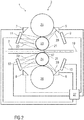
- Figure 1 shows schematically a side view of a first embodiment of a rolling device 1 according to the invention for rolling a rolling stock 2.
- the rolling stock 2 is a metallic rolled strip, for example a steel strip, the thickness of which is reduced by the rolling.
- the rolling device 1 comprises a reversing roll stand 3, two spray bars 5, 6, four cooling bars 9 to 12 and a control unit 27.
- the reversing roll stand 3 has two work rolls 23, 24 and two backup rolls 25, 26 arranged one above the other, one back-up roll 25 being arranged above the two work rolls 23, 24 and the other back-up roll 26 being arranged below the two work rolls 23, 24.
- the two work rolls 23, 24 are spaced apart from one another by a roll gap 17.
- the work rolls 23, 24 are set in rotation and the rolling stock 2 is guided through the roll gap 17 by the rotating work rolls 23, 24 alternately in two opposite rolling directions.
- a rolling pass is shown in which the rolling stock 2 is guided from left to right through the roll gap 17, so that the left side of the reversing roll stand 3 is the entry side of the roll pass and the right side of the reversing roll stand 3 is the exit side of the roll pass.
- the rolling stock 2 is passed from right to left through the roll gap 17, so that the right side of the reversing roll stand 3 is the inlet side of the roll pass and the left side of the reversing roll stand 3 is the exit side of the roll pass.
- the spray bars 5, 6 are arranged on one side of the reversing roll stand 3, one spray bar 5 being arranged above a rolling stock level 19 in which the rolling stock 2 is guided and the other spray bar 6 being arranged below the rolling stock level 19.
- Each spray bar 5, 6 is set up to spray a mixture 20 (aerosol) of a lubricant 21, for example a lubricating oil, and a carrier gas onto the surface of a work roll 23, 24.
- each spray bar 5, 6 has an atomizing device (not shown in detail) to which the lubricant 21 and the carrier gas are supplied and which atomizes the lubricant 21 in the carrier gas.
- each spray bar 5, 6 also does not have Spray nozzles shown in more detail, which are set up to spray the mixture 20 onto the surface of a work roll 23, 24.
- the cooling bars 9 to 12 are arranged on both sides of the reversing roll stand 3, with a cooling bar 9, 11 being arranged above the rolling stock plane 19 and a cooling bar 10, 12 being arranged below the rolling stock level 19 on each side of the reversing roll stand 3.
- Each cooling beam 9 to 12 is set up to output a coolant 22 onto a surface of a work roll 23, 24 and / or a surface of the rolling stock 2.
- each cooling bar 9 to 12 has, for example, spray nozzles (not shown in more detail) through which the coolant 21 can be dispensed.
- the coolant 22 is, for example, water or a cooling emulsion that contains water and a rolling oil, the oil content of the cooling emulsion being less than ten percent by volume.
- the coolant 22 can contain at least one emulsifier which improves the adhesion of the lubricant 21 to the work rolls 23, 24 and / or to the rolling stock 2.
- the spray bars 5, 6 and the cooling bars 9 to 12 can be controlled by the control unit 27.
- the control unit 27 is set up to control the spray bars 5, 6 and the cooling bars 9 to 12 in such a way that the mixture 20 is sprayed exclusively on the outlet side of a rolling pass onto the work rolls 23, 24 and the coolant 22 exclusively on the inlet side of a rolling pass is output onto the work rolls 23, 24 and / or onto the rolling stock 2. Since the in Figure 1 The embodiment shown, the spray bars 5, 6 are only arranged on one side of the reversing roll stand 3, in this embodiment the mixture 20 is thus only sprayed onto the work rolls 23, 24 at most every second rolling pass.
- FIG Figure 2 shows schematically a side view of a second embodiment of a rolling device 1 according to the invention for rolling a rolling stock 2.
- This embodiment differs from that in FIG Figure 1
- the first embodiment shown only by the number and arrangement of spray bars 5 to 8.
- a spray bar 5, 7 and a cooling bar 9, 11 above the rolling stock level 19 and a spray bar 6, 8 and a cooling bar are on each side of the reversing roll stand 3 10, 12 arranged below the plane 19 of the rolling stock.
- control unit 27 is set up to control the spray bars 5 to 8 and the cooling bars 9 to 12 in such a way that the mixture 20 is sprayed onto the work rolls 23, 24 exclusively on one outlet side of a rolling pass and the coolant 22 exclusively is issued on an inlet side of a rolling pass on the work rolls 23, 24 and / or on the rolling stock 2.
- spray bars 5 to 8 are arranged on both sides of the reversing roll stand 3, in contrast to the one in FIG Figure 1
- the mixture 20 can be sprayed onto the work rolls 23, 24 for each rolling pass.
- FIG 2 is like in Figure 1 a rolling pass is shown in which the rolling stock 2 is guided from left to right through the roll gap 17 so that the inlet side of the rolling pass is the left side of the reversing roll stand 3 and the outlet side of the rolling pass is the right side of the reversing roll stand 3. Accordingly, the work rolls 23, 24 in this rolling pass only from the right spray bars 5, 6 arranged by the reversing roll stand 3 are sprayed with the mixture 20 and the coolant 22 is only output from the cooling bars 11, 12 arranged to the left of the reversing roll stand 3 onto the work rolls 23, 24 and / or the rolling stock 2.
Landscapes
- Engineering & Computer Science (AREA)
- Mechanical Engineering (AREA)
- Metal Rolling (AREA)
Abstract
Description
- Die Erfindung betrifft ein Verfahren und eine Walzvorrichtung zum Walzen eines Walzguts mit einem Reversierwalzgerüst.
- In einem Reversierwalzgerüst wird ein Walzgut abwechselnd in zwei einander entgegensetzten Walzrichtungen durch einen Walzspalt zwischen zwei rotierenden Arbeitswalzen geführt, um die Dicke des Walzguts zu reduzieren. Das Walzgut ist ein in der Regel metallisches Walzband. Ein Durchgang des Walzguts durch den Walzspalt wird als ein Walzstich bezeichnet. Beim ersten Walzstich läuft das Walzgut dabei in den Walzspalt mit einer relativ hohen Beizrauheit ein, welche danach bei jedem weiteren Walzstich weiter eingeglättet wird. Die Reibung des Walzguts mit den Arbeitswalzen ist in den ersten Walzstichen dementsprechend hoch. Die Folge sind hohe Walzkräfte sowie negative Auswirkungen des Walzabriebs auf die Bandsauberkeit des Walzguts. Zu hohe Walzkräfte führen im Reversierwalzgerüst unter Umständen zu einer höheren Anzahl an benötigten Walzstichen und damit zu längeren Produktionszeiten. Zu hohe Reibwerte können auch dazu führen, dass besonders dünne Produkte überhaupt nicht hergestellt werden können, da wegen der elastischen Walzenverformung ab einer bestimmten Dicke des Walzguts keine weitere Reduktion der Dicke möglich ist. Schlechte Bandsauberkeit hat verminderte Produktqualität (im Fall eines kaltgewalzten Endprodukts) beziehungsweise zusätzlichen Aufwand in den nachfolgenden Bearbeitungsschritten (im Fall eines geglühten und/oder verzinkten Endprodukts) zur Folge. Um die Reibung des Walzguts mit den Arbeitswalzen zu reduzieren, wird der Walzspalt in der Regel geschmiert. Ferner werden die Arbeitswalzen in der Regel gekühlt, um die Temperatur und den Verschleiß der Arbeitswalzen zu reduzieren.
-
EP 2 651 577 B1 offenbart ein Verfahren und eine Vorrichtung zum Aufbringen eines Schmiermittels beim Walzen eines metallischen Walzbandes, das in einem Walzspalt zwischen zwei Arbeitswalzen hindurch geführt wird. Dabei wird in einer Zerstäubungseinrichtung ein Gemisch aus dem Schmiermittel und einem Trägergas erzeugt, und das Gemisch wird mit Sprühdüsen auf die Oberfläche zumindest einer Arbeitswalze und/oder auf die Oberfläche des Walzbandes aufgebracht. -
EP 3 092 088 B1 offenbart ein Verfahren und eine Vorrichtung zum Aufbringen eines Schmieröls beim Walzen eines metallischen flachen Walzguts in einem Walzgerüst. Das Schmieröl wird dazu mittels Druckluft zu einem Aerosol zerstäubt, das mittels mehrerer nebeneinander angeordneter Spritzdüsen auf das Walzgut und/oder mindestens eine Walze des Walzgerüsts aufgespritzt wird. - Der Erfindung liegt die Aufgabe zugrunde, ein verbessertes Verfahren und eine verbesserte Walzvorrichtung zum Walzen eines Walzguts mit einem Reversierwalzgerüst anzugeben.
- Die Aufgabe wird erfindungsgemäß durch ein Verfahren mit den Merkmalen des Anspruchs 1 und eine Walzvorrichtung mit den Merkmalen des Anspruchs 10 gelöst.
- Vorteilhafte Ausgestaltungen der Erfindung sind Gegenstand der Unteransprüche.
- Bei dem erfindungsgemäßen Verfahren zum Walzen eines Walzguts wird das Walzgut abwechselnd in zwei einander entgegensetzten Walzrichtungen durch einen Walzspalt zwischen zwei Arbeitswalzen eines Reversierwalzgerüsts geführt. In eine Kontaktzone, in der das Walzgut an den Arbeitswalzen anliegt, wird ein Schmiermittel, beispielsweise ein Schmieröl, zur Schmierung der Kontaktzone eingebracht und auf das Walzgut oder/und die Arbeitswalzen wird ein Kühlmittel aufgebracht. Das Schmiermittel wird in einem Gemisch mit einem Trägergas ausgegeben, wobei das Gemisch ausschließlich auf einer Auslaufseite eines Walzstichs, auf der das Walzgut aus dem Walzspalt herausläuft, auf die Arbeitswalzen oder/und auf das Walzgut gesprüht wird. Das Kühlmittel wird ausschließlich auf einer Einlaufseite eines Walzstichs, auf der das Walzgut in den Walzspalt einläuft, auf die Arbeitswalzen oder/und auf das Walzgut ausgegeben. Da je zwei aufeinander folgende Walzstiche unterschiedliche Walzrichtungen aufweisen, ist die Einlaufseite eines Walzstichs eine Seite des Reversierwalzgerüsts, die die Auslaufseite des darauf folgenden Walzstichs ist, und die Auslaufseite eines Walzstichs ist eine Seite des Reversierwalzgerüsts, die die Einlaufseite des darauf folgenden Walzstichs ist.
- Mit anderen Worten sieht die Erfindung vor, ein Walzgut beim Walzen in einem Reversierwalzgerüst nur auslaufseitig mit einem Schmiermittel zu schmieren und nur einlaufseitig mit einem Kühlmittel zu kühlen, wobei das Schmiermittel in einem Gemisch (Aerosol) mit einem Trägergas auf die Arbeitswalzen oder/und auf das Walzgut gesprüht wird. Vorzugsweise wird das Schmiermittel nur auf die Arbeitswalzen aufgebracht, weil dabei weniger Schmiermittel aus dem Reversierwalzgerüst herausgetragen wird, was den Schmiermittelverbrauch reduziert. Das Aufbringen des Schmiermittels durch Besprühen der Arbeitswalzen oder/und des Walzguts mit einem Gemisch aus dem Schmiermittel und einem Trägergas hat, beispielsweise gegenüber dem Aufbringen einer Schmieremulsion, den Vorteil, dass das Schmiermittel sehr gezielt nur auf bestimmte Oberflächenbereiche der Arbeitswalzen oder/und des Walzguts aufgetragen werden kann, um den Schmiermittelauftrag auf die Kontaktzone zu konzentrieren, in der das Walzgut in dem Walzspalt an den Arbeitswalzen anliegt. Dadurch kann insbesondere die Schmierung auf eine Minimalmengenschmierung (so genannte Minimum Quantity Lubrication) mit einer minimalen Schmiermittelmenge reduziert werden.
- Das nur einlaufseitige Ausgeben von Kühlmittel auf die Arbeitswalzen oder/und auf das Walzgut verhindert, dass größere Mengen des Kühlmittels auslaufseitig aus dem Reversierwalzgerüst herausgetragen werden, was gerade bei höheren Walzgeschwindigkeiten des Walzguts aufgrund der Massenträgheit des Kühlmittels auftreten kann. Das nur auslaufseitige Besprühen der Arbeitswalzen oder/und des Walzguts mit dem Gemisch aus dem Schmiermittel und dem Trägergas berücksichtigt, dass bei einem einlaufseitigen Besprühen und gleichzeitigem einlaufseitigen Ausgeben von Kühlmittel auf die Arbeitswalzen oder/und auf das Walzgut das Kühlmittel verhindern kann, dass das Gemisch aus dem Schmiermittel und dem Trägergas die Arbeitswalzen oder/und auf das Walzgut erreicht. Dabei wird ausgenutzt, dass Schmiermittel, das durch Besprühen der Arbeitswalzen oder/und des Walzguts mit dem Gemisch aus dem Schmiermittel und dem Trägergas aufgebracht wird, besser an den Arbeitswalzen oder/und an dem Walzgut haftet als beispielsweise ein Schmiermittel, das mit einer Emulsion aufgebracht wird, so dass kein ein- und auslaufseitiges Ausbringen von Schmiermittel erforderlich ist, da auslaufseitig aufgebrachtes Schmiermittel aufgrund seiner Haftung auch einlaufseitig wirkt.
- Als Kühlmittel wird beispielsweise Wasser oder eine Kühlemulsion verwendet. Die Kühlemulsion enthält beispielsweise ein Walzöl mit einem Anteil von weniger als zehn Volumenprozent an der Kühlemulsion. Ferner kann das Kühlmittel wenigstens einen Emulgator enthalten, der die Entmischung der Komponenten (beispielsweise Wasser und Walzöl) der Kühlemulsion verhindert und ein Anhaften des Schmiermittels an den Arbeitswalzen oder/und an dem Walzgut verbessert. Die Verwendung von reinem Wasser als Kühlmittel hat gegenüber der Verwendung einer Kühlemulsion den Vorteil, dass die Temperatur des Kühlmittels niedriger gehalten werden kann als bei einer Emulsionskühlung (eine Kühlemulsion benötigt eine gewisse Mindesttemperatur), wodurch die Kühlwirkung verbessert wird. Außerdem entfällt bei einer reinen Wasserkühlung der Aufwand (Installation, laufende Betriebskosten) für die Herstellung und Wiederaufbereitung der Kühlemulsion. Durch die Beimischung eines Emulgators, der ein Anhaften des Schmiermittels an den Arbeitswalzen oder/und an dem Walzgut verbessert, kann der Schmiermittelbedarf vorteilhaft weiter reduziert werden.
- Ferner kann vorgesehen sein, dass das Gemisch aus dem Schmiermittel und dem Trägergas nur beim Durchführen des Walzguts durch den Walzspalt in einer der beiden Walzrichtungen auf die Arbeitswalzen oder/und auf das Walzgut gesprüht wird. Dadurch brauchen Sprühbalken zum Ausgeben des Gemisches nur auf einer Seite des Reversierwalzgerüsts angeordnet werden.
- Alternativ kann vorgesehen sein, dass das Gemisch aus dem Schmiermittel und dem Trägergas beim Durchführen des Walzguts durch den Walzspalt in beiden Walzrichtungen auf die Arbeitswalzen oder/und auf das Walzgut gesprüht wird. Dies erfordert Sprühbalken zum Ausgeben des Gemisches auf beiden Seiten des Reversierwalzgerüsts, ermöglicht jedoch eine flexiblere Schmierung, da bei jedem beliebigen Walzstich Schmiermittel auslaufseitig auf die Arbeitswalzen oder/und auf das Walzgut aufgebracht werden kann.
- Ferner kann vorgesehen sein, dass beim erstmaligen Durchführen des Walzguts durch den Walzspalt (das heißt beim ersten Walzstich) ein Walzgutkopf des Walzguts, der als erster Bereich des Walzguts durch den Walzspalt geführt wird, mit einer geringeren Geschwindigkeit als der übrige Bereich des Walzguts durch den Walzspalt geführt wird. Dabei kann des Weiteren vorgesehen sein, dass beim erstmaligen Durchführen des Walzgutkopfes durch den Walzspalt kein Kühlmittel auf die Arbeitswalzen oder/und auf das Walzgut ausgegeben wird. Bei dieser Ausgestaltung der Erfindung entsteht durch das langsamere Durchführen des Walzgutkopfs durch den Walzspalt beim ersten Walzstich kein so hoher Kühlbedarf wie beim Durchführen mit einer höheren Geschwindigkeit. Dadurch kann auf ein Kühlen während des Einfädelns des Walzguts in das Reversierwalzgerüst verzichtet werden. Dies stellt in der Regel kein Problem dar, da der Walzgutkopf meist ohnehin eine reduzierte Qualität aufweist und daher abgeschrottet wird.
- Eine erfindungsgemäße Walzvorrichtung zum Durchführen des erfindungsgemäßen Verfahrens umfasst
- ein Reversierwalzgerüst mit zwei Arbeitswalzen,
- wenigstens einen Sprühbalken, der dazu eingerichtet ist, das Gemisch aus dem Schmiermittel und dem Trägergas auf eine Arbeitswalze oder/und auf das Walzgut zu sprühen,
- wenigstens einen Kühlbalken, der dazu eingerichtet ist, das Kühlmittel auf eine Arbeitswalze oder/und auf das Walzgut auszugeben, und
- eine Steuereinheit, die dazu eingerichtet ist, jeden Sprühbalken und jeden Kühlbalken derart zu steuern, dass das Gemisch aus dem Schmiermittel und dem Trägergas ausschließlich auf einer Auslaufseite eines Walzstichs und das Kühlmittel ausschließlich auf einer Einlaufseite eines Walzstichs ausgegeben wird.
- Eine erfindungsgemäße Walzvorrichtung ermöglicht die Durchführung des erfindungsgemäßen Verfahrens. Daher entsprechen die Vorteile einer erfindungsgemäßen Walzvorrichtung den oben bereits genannten Vorteilen des erfindungsgemäßen Verfahrens.
- Bei einer Ausgestaltung der Walzvorrichtung sind alle Sprühbalken auf derselben Seite des Reversierwalzgerüsts angeordnet. Diese Ausgestaltung der Walzvorrichtung ist gegenüber einer Anordnung von Sprühbalken auf beiden Seiten des Reversierwalzgerüsts platz-, aufwand- und kostensparend und berücksichtigt, dass aufgrund des oben bereits diskutierten guten Haftens des Schmiermittels an den Arbeitswalzen oder/und an dem Walzgut auf eine Schmierung bei jedem Walzstich in der Regel verzichtet werden kann.
- Bei einer weiteren Ausgestaltung der Walzvorrichtung sind auf wenigstens einer Seite des Reversierwalzgerüsts wenigstens ein Sprühbalken und wenigstens ein Kühlbalken angeordnet.
- Bei einer weiteren Ausgestaltung der Walzvorrichtung sind auf wenigstens einer Seite des Reversierwalzgerüsts wenigstens ein Sprühbalken oberhalb einer Walzgutebene, in der das Walzgut geführt wird, und wenigstens ein Sprühbalken unterhalb der Walzgutebene angeordnet. Ferner können auf wenigstens einer Seite des Reversierwalzgerüsts wenigstens ein Kühlbalken oberhalb der Walzgutebene und wenigstens ein Kühlbalken unterhalb der Walzgutebene angeordnet sein. Diese Ausgestaltungen der Walzvorrichtung ermöglichen vorteilhaft ein Schmieren und/oder Kühlen der Arbeitswalzen oder/und des Walzguts auf beiden Seiten des Walzguts.
- Die oben beschriebenen Eigenschaften, Merkmale und Vorteile dieser Erfindung sowie die Art und Weise, wie diese erreicht werden, werden klarer und deutlicher verständlich im Zusammenhang mit der folgenden Beschreibung von Ausführungsbeispielen, die im Zusammenhang mit den Zeichnungen näher erläutert werden. Dabei zeigen:
-
FIG 1 schematisch eine Seitenansicht eines ersten Ausführungsbeispiels einer erfindungsgemäßen Walzvorrichtung, -
FIG 2 schematisch eine Seitenansicht eines zweiten Ausführungsbeispiels einer erfindungsgemäßen Walzvorrichtung. - Einander entsprechende Teile sind in den Figuren mit denselben Bezugszeichen versehen.
-
Figur 1 zeigt schematisch eine Seitenansicht eines ersten Ausführungsbeispiels einer erfindungsgemäßen Walzvorrichtung 1 zum Walzen eines Walzguts 2. Das Walzgut 2 ist ein metallisches Walzband, beispielsweise ein Stahlband, dessen Dicke durch das Walzen reduziert wird. Die Walzvorrichtung 1 umfasst ein Reversierwalzgerüst 3, zwei Sprühbalken 5, 6, vier Kühlbalken 9 bis 12 und eine Steuereinheit 27. - Das Reversierwalzgerüst 3 weist zwei übereinander angeordnete Arbeitswalzen 23, 24 und zwei Stützwalzen 25, 26 auf, wobei eine Stützwalze 25 oberhalb der beiden Arbeitswalzen 23, 24 angeordnet ist und die andere Stützwalze 26 unterhalb der beiden Arbeitswalzen 23, 24 angeordnet ist. Die beiden Arbeitswalzen 23, 24 sind voneinander durch einen Walzspalt 17 beabstandet.
- Zum Walzen des Walzguts 2 werden die Arbeitswalzen 23, 24 in Rotation versetzt und das Walzgut 2 wird durch die rotierenden Arbeitswalzen 23, 24 abwechselnd in zwei einander entgegensetzten Walzrichtungen durch den Walzspalt 17 geführt. In
Figur 1 ist ein Walzstich gezeigt, bei dem das Walzgut 2 von links nach rechts durch den Walzspalt 17 geführt wird, so dass die linke Seite des Reversierwalzgerüsts 3 die Einlaufseite des Walzstichs ist und die rechte Seite des Reversierwalzgerüsts 3 die Auslaufseite des Walzstichs ist. Bei dem darauf folgenden Walzstich wird das Walzgut 2 von rechts nach links durch den Walzspalt 17 geführt, so dass die rechte Seite des Reversierwalzgerüsts 3 die Einlaufseite des Walzstichs ist und die linke Seite des Reversierwalzgerüsts 3 die Auslaufseite des Walzstichs ist. - Die Sprühbalken 5, 6 sind auf einer Seite des Reversierwalzgerüsts 3 angeordnet, wobei ein Sprühbalken 5 oberhalb einer Walzgutebene 19, in der das Walzgut 2 geführt wird, angeordnet ist und der andere Sprühbalken 6 unterhalb der Walzgutebene 19 angeordnet ist. Jeder Sprühbalken 5, 6 ist dazu eingerichtet, ein Gemisch 20 (Aerosol) aus einem Schmiermittel 21, beispielsweise einem Schmieröl, und einem Trägergas auf die Oberfläche einer Arbeitswalze 23, 24 zu sprühen. Zum Erzeugen des Gemisches 20 weist jeder Sprühbalken 5, 6 eine nicht näher dargestellte Zerstäubungseinrichtung auf, welcher das Schmiermittel 21 und das Trägergas zugeführt werden und welche das Schmiermittel 21 in dem Trägergas zerstäubt. Zum Ausgeben des Gemisches 20 weist jeder Sprühbalken 5, 6 ebenfalls nicht näher dargestellte Sprühdüsen auf, die dazu eingerichtet sind, das Gemisch 20 auf die Oberfläche einer Arbeitswalze 23, 24 zu sprühen.
- Die Kühlbalken 9 bis 12 sind beidseitig des Reversierwalzgerüsts 3 angeordnet, wobei auf jeder Seite des Reversierwalzgerüsts 3 ein Kühlbalken 9, 11 oberhalb der Walzgutebene 19 angeordnet ist und ein Kühlbalken 10, 12 unterhalb der Walzgutebene 19 angeordnet ist. Jeder Kühlbalken 9 bis 12 ist dazu eingerichtet, ein Kühlmittel 22 auf eine Oberfläche einer Arbeitswalze 23, 24 oder/und eine Oberfläche des Walzguts 2 auszugeben. Dazu weist jeder Kühlbalken 9 bis 12 beispielsweise nicht näher dargestellte Spritzdüsen auf, durch die das Kühlmittel 21 ausgebbar ist. Das Kühlmittel 22 ist beispielsweise Wasser oder eine Kühlemulsion, die Wasser und ein Walzöl enthält, wobei der Ölgehalt der Kühlemulsion weniger als zehn Volumenprozent beträgt. Ferner kann das Kühlmittel 22 wenigstens einen Emulgator enthalten, der ein Anhaften des Schmiermittels 21 an den Arbeitswalzen 23, 24 oder/und an dem Walzgut 2 verbessert.
- Die Sprühbalken 5, 6 und die Kühlbalken 9 bis 12 sind durch die Steuereinheit 27 steuerbar. Die Steuereinheit 27 ist dazu eingerichtet, die Sprühbalken 5, 6 und die Kühlbalken 9 bis 12 derart zu steuern, dass das Gemisch 20 ausschließlich auf der Auslaufseite eines Walzstichs auf die Arbeitswalzen 23, 24 gesprüht wird und das Kühlmittel 22 ausschließlich auf der Einlaufseite eines Walzstichs auf die Arbeitswalzen 23, 24 oder/und auf das Walzgut 2 ausgegeben wird. Da bei dem in
Figur 1 gezeigten Ausführungsbeispiel die Sprühbalken 5, 6 nur auf einer Seite des Reversierwalzgerüsts 3 angeordnet sind, wird bei diesem Ausführungsbeispiel das Gemisch 20 also nur höchstens bei jedem zweiten Walzstich auf die Arbeitswalzen 23, 24 gesprüht. - Vorzugsweise wird ferner bei dem ersten Walzstich ein Walzgutkopf des Walzguts 2, der als erster Bereich des Walzguts 2 durch den Walzspalt 17 geführt wird, mit einer geringeren Geschwindigkeit als der übrige Bereich des Walzguts 2 durch den Walzspalt 17 geführt und beim erstmaligen Durchführen des Walzgutkopfes durch den Walzspalt 17 wird kein Kühlmittel 22 auf die Arbeitswalzen 23, 24 oder/und auf das Walzgut 2 ausgegeben.
-
Figur 2 zeigt schematisch eine Seitenansicht eines zweiten Ausführungsbeispiels einer erfindungsgemäßen Walzvorrichtung 1 zum Walzen eines Walzguts 2. Dieses Ausführungsbeispiel unterscheidet sich von dem inFigur 1 gezeigten ersten Ausführungsbeispiel lediglich durch die Anzahl und Anordnung von Sprühbalken 5 bis 8. Bei den zweiten Ausführungsbeispiel sind auf jeder Seite des Reversierwalzgerüsts 3 ein Sprühbalken 5, 7 und ein Kühlbalken 9, 11 oberhalb der Walzgutebene 19 und ein Sprühbalken 6, 8 und ein Kühlbalken 10, 12 unterhalb der Walzgutebene 19 angeordnet. - Die Steuereinheit 27 ist analog zu dem ersten Ausführungsbeispiel dazu eingerichtet, die Sprühbalken 5 bis 8 und die Kühlbalken 9 bis 12 derart zu steuern, dass das Gemisch 20 ausschließlich auf einer Auslaufseite eines Walzstichs auf die Arbeitswalzen 23, 24 gesprüht wird und das Kühlmittel 22 ausschließlich auf einer Einlaufseite eines Walzstichs auf die Arbeitswalzen 23, 24 oder/und auf das Walzgut 2 ausgegeben wird. Da bei dem in
Figur 2 gezeigten Ausführungsbeispiel Sprühbalken 5 bis 8 auf beiden Seiten des Reversierwalzgerüsts 3 angeordnet sind, kann im Unterschied zu dem inFigur 1 gezeigten Ausführungsbeispiel das Gemisch 20 bei jedem Walzstich auf die Arbeitswalzen 23, 24 gesprüht werden. InFigur 2 ist wie inFigur 1 ein Walzstich gezeigt, bei dem das Walzgut 2 von links nach rechts durch den Walzspalt 17 geführt wird, so dass die Einlaufseite des Walzstichs die linke Seite des Reversierwalzgerüsts 3 ist und die Auslaufseite des Walzstichs die rechte Seite des Reversierwalzgerüsts 3 ist. Dementsprechend werden die Arbeitswalzen 23, 24 bei diesem Walzstich nur von den rechts von dem Reversierwalzgerüst 3 angeordneten Sprühbalken 5, 6 mit dem Gemisch 20 besprüht und das Kühlmittel 22 wird nur von den links von dem Reversierwalzgerüst 3 angeordneten Kühlbalken 11, 12 auf die Arbeitswalzen 23, 24 und/oder das Walzgut 2 ausgegeben. - Obwohl die Erfindung im Detail durch bevorzugte Ausführungsbeispiele näher illustriert und beschrieben wurde, so ist die Erfindung nicht durch die offenbarten Beispiele eingeschränkt und andere Variationen können vom Fachmann hieraus abgeleitet werden, ohne den Schutzumfang der Erfindung zu verlassen.
-
- 1
- Walzvorrichtung
- 2
- Walzgut
- 3
- Reversierwalzgerüst
- 5 bis 8
- Sprühbalken
- 9 bis 12
- Kühlbalken
- 17
- Walzspalt
- 19
- Walzgutebene
- 20
- Gemisch
- 21
- Schmiermittel
- 22
- Kühlmittel
- 23, 24
- Arbeitswalze
- 25, 26
- Stützwalze
- 27
- Steuereinheit
Claims (14)
- Verfahren zum Walzen eines Walzguts (2), wobei- das Walzgut (2) abwechselnd in zwei einander entgegensetzten Walzrichtungen durch einen Walzspalt (17) zwischen zwei Arbeitswalzen (23, 24) eines Reversierwalzgerüsts (3) geführt wird,- in eine Kontaktzone, in der das Walzgut (2) an den Arbeitswalzen (23, 24) anliegt, ein Schmiermittel (21) zur Schmierung der Kontaktzone eingebracht wird,- und ein Kühlmittel (22) auf die Arbeitswalzen (23, 24) oder/und auf das Walzgut (2) aufgebracht wird, wobei- das Schmiermittel (21) in einem Gemisch (20) mit einem Trägergas ausgegeben wird, wobei das Gemisch (20) ausschließlich auf einer Auslaufseite eines Walzstichs, auf der das Walzgut (2) aus dem Walzspalt (17) herausläuft, auf die Arbeitswalzen (23, 24) oder/und auf das Walzgut (2) gesprüht wird,- und das Kühlmittel (22) ausschließlich auf einer Einlaufseite eines Walzstichs, auf der das Walzgut (2) in den Walzspalt (17) einläuft, auf die Arbeitswalzen (23, 24) oder/und auf das Walzgut (2) ausgegeben wird.
- Verfahren nach Anspruch 1, wobei das Schmiermittel (21) ein Schmieröl ist.
- Verfahren nach Anspruch 1 oder 2, wobei als Kühlmittel (22) Wasser verwendet wird.
- Verfahren nach Anspruch 1 oder 2, wobei als Kühlmittel (22) eine Kühlemulsion verwendet wird.
- Verfahren nach Anspruch 4, wobei das Kühlmittel (22) wenigstens einen Emulgator enthält, der ein Anhaften des Schmiermittels (21) an den Arbeitswalzen (23, 24) oder/und an dem Walzgut (2) verbessert.
- Verfahren nach einem der vorhergehenden Ansprüche, wobei das Gemisch (20) aus dem Schmiermittel (21) und dem Trägergas nur beim Durchführen des Walzguts (2) durch den Walzspalt (17) in einer der beiden Walzrichtungen auf die Arbeitswalzen (23, 24) oder/und auf das Walzgut (2) gesprüht wird.
- Verfahren nach einem der Ansprüche 1 bis 5, wobei das Gemisch (20) aus dem Schmiermittel (21) und dem Trägergas beim Durchführen des Walzguts (2) durch den Walzspalt (17) in beiden Walzrichtungen auf die Arbeitswalzen (23, 24) oder/und auf das Walzgut (2) gesprüht wird.
- Verfahren nach einem der vorhergehenden Ansprüche, wobei beim erstmaligen Durchführen des Walzguts (2) durch den Walzspalt (17) ein Walzgutkopf des Walzguts (2), der als erster Bereich des Walzguts (2) durch den Walzspalt (17) geführt wird, mit einer geringeren Geschwindigkeit als der übrige Bereich des Walzguts (2) durch den Walzspalt (17) geführt wird.
- Verfahren nach Anspruch 8, wobei beim erstmaligen Durchführen des Walzgutkopfes durch den Walzspalt (17) kein Kühlmittel (22) auf die Arbeitswalzen (23, 24) oder/und auf das Walzgut (2) ausgegeben wird.
- Walzvorrichtung (1) zum Durchführen des Verfahrens nach einem der vorhergehenden Ansprüche, die Walzvorrichtung (1) umfassend- ein Reversierwalzgerüst (3) mit zwei Arbeitswalzen (23, 24),- wenigstens einen Sprühbalken (5 bis 8), der dazu eingerichtet ist, das Gemisch (20) aus dem Schmiermittel (21) und dem Trägergas auf eine Arbeitswalze (23, 24) oder/und auf das Walzgut (2) zu sprühen,- wenigstens einen Kühlbalken (9 bis 12), der dazu eingerichtet ist, das Kühlmittel (22) auf eine Arbeitswalze (23, 24) oder/und auf das Walzgut (2) auszugeben, und- eine Steuereinheit (27), die dazu eingerichtet ist, jeden Sprühbalken (5 bis 8) und jeden Kühlbalken (9 bis 12) derart zu steuern, dass das Gemisch (20) aus dem Schmiermittel (21) und dem Trägergas ausschließlich auf einer Auslaufseite eines Walzstichs und das Kühlmittel (22) ausschließlich auf einer Einlaufseite eines Walzstichs ausgegeben wird.
- Walzvorrichtung (1) nach Anspruch 10, wobei alle Sprühbalken (5, 6) auf derselben Seite des Reversierwalzgerüsts (3) angeordnet sind.
- Walzvorrichtung (1) nach Anspruch 10 oder 11, wobei auf wenigstens einer Seite des Reversierwalzgerüsts (3) wenigstens ein Sprühbalken (5 bis 8) und wenigstens ein Kühlbalken (9 bis 12) angeordnet sind.
- Walzvorrichtung (1) nach einem der Ansprüche 10 bis 12, wobei auf wenigstens einer Seite des Reversierwalzgerüsts (3) wenigstens ein Sprühbalken (5, 7) oberhalb einer Walzgutebene (19), in der das Walzgut (2) geführt wird, angeordnet ist und wenigstens ein Sprühbalken (6, 8) unterhalb der Walzgutebene (19) angeordnet ist.
- Walzvorrichtung (1) nach einem der Ansprüche 10 bis 13, wobei auf wenigstens einer Seite des Reversierwalzgerüsts (3) wenigstens ein Kühlbalken (9, 11) oberhalb einer Walzgutebene (19), in der das Walzgut (2) geführt wird, angeordnet ist und wenigstens ein Kühlbalken (10, 12) unterhalb der Walzgutebene (19) angeordnet ist.
Priority Applications (4)
| Application Number | Priority Date | Filing Date | Title |
|---|---|---|---|
| EP19171923.6A EP3733317B1 (de) | 2019-04-30 | 2019-04-30 | Walzen eines walzguts |
| CN202080032363.7A CN113727789B (zh) | 2019-04-30 | 2020-04-23 | 轧件的轧制 |
| US17/607,514 US11529660B2 (en) | 2019-04-30 | 2020-04-23 | Rolling of a rolled material |
| PCT/EP2020/061368 WO2020221654A1 (de) | 2019-04-30 | 2020-04-23 | Walzen eines walzguts |
Applications Claiming Priority (1)
| Application Number | Priority Date | Filing Date | Title |
|---|---|---|---|
| EP19171923.6A EP3733317B1 (de) | 2019-04-30 | 2019-04-30 | Walzen eines walzguts |
Publications (2)
| Publication Number | Publication Date |
|---|---|
| EP3733317A1 true EP3733317A1 (de) | 2020-11-04 |
| EP3733317B1 EP3733317B1 (de) | 2022-10-05 |
Family
ID=66349341
Family Applications (1)
| Application Number | Title | Priority Date | Filing Date |
|---|---|---|---|
| EP19171923.6A Active EP3733317B1 (de) | 2019-04-30 | 2019-04-30 | Walzen eines walzguts |
Country Status (4)
| Country | Link |
|---|---|
| US (1) | US11529660B2 (de) |
| EP (1) | EP3733317B1 (de) |
| CN (1) | CN113727789B (de) |
| WO (1) | WO2020221654A1 (de) |
Families Citing this family (3)
| Publication number | Priority date | Publication date | Assignee | Title |
|---|---|---|---|---|
| IT201900005442A1 (it) * | 2019-04-09 | 2020-10-09 | Danieli Off Mecc | Processo di laminazione a freddo di un prodotto in alluminio e relativo impianto di laminazione a freddo |
| EP4501480A1 (de) | 2023-08-03 | 2025-02-05 | Primetals Technologies Austria GmbH | Verfahren und system zum aufbringen eines schmiermittels beim kaltwalzen eines walzguts in einem walzgerüst |
| DE102024209337A1 (de) | 2024-09-26 | 2026-03-26 | Sms Group Gmbh | Verfahren und Reversierwalzwerk zum Walzen eines metallischen Bandes |
Citations (4)
| Publication number | Priority date | Publication date | Assignee | Title |
|---|---|---|---|---|
| WO2013029886A1 (de) * | 2011-08-30 | 2013-03-07 | Siemens Vai Metals Technologies Gmbh | Reversierwalzwerk und betriebsverfahren für ein reversierwalzwerk |
| EP2651577A1 (de) | 2010-12-16 | 2013-10-23 | Siemens VAI Metals Technologies GmbH | Verfahren und vorrichtung zum aufbringen eines schmiermittels beim walzen eines metallischen walzgutes |
| EP3092088A1 (de) | 2014-01-08 | 2016-11-16 | Primetals Technologies Austria GmbH | Schmierung mit spritzdüsen mit mehreren öleintrittsöffnungen |
| EP3461566A1 (de) * | 2017-10-02 | 2019-04-03 | Primetals Technologies Austria GmbH | Walzen eines walzguts |
Family Cites Families (8)
| Publication number | Priority date | Publication date | Assignee | Title |
|---|---|---|---|---|
| SU1235585A1 (ru) | 1984-12-28 | 1986-06-07 | Институт черной металлургии | Способ холодной прокатки полос на реверсивном стане |
| RU2212962C2 (ru) | 2001-12-25 | 2003-09-27 | Открытое акционерное общество "Новолипецкий металлургический комбинат" | Способ холодной прокатки полос в непрерывном многоклетьевом стане |
| JP4355279B2 (ja) * | 2004-11-22 | 2009-10-28 | 新日本製鐵株式会社 | 冷間圧延における潤滑油供給方法 |
| DE102007032485A1 (de) * | 2006-12-15 | 2008-06-19 | Sms Demag Ag | Verfahren und Schmiermittelauftragsvorrichtung zum Regeln der Planheit und/oder der Rauheit eines Metallbandes |
| CN101396694A (zh) * | 2008-10-31 | 2009-04-01 | 莱芜钢铁股份有限公司 | 一种轧辊气雾冷却方法及装置 |
| CN106269896B (zh) * | 2015-06-12 | 2018-03-30 | 宝山钢铁股份有限公司 | 冷轧单机架可逆轧制控制设备及方法 |
| CN106345827A (zh) * | 2016-11-15 | 2017-01-25 | 王红昊 | 一种金属板带轧制润滑冷却工艺 |
| CN107838197A (zh) * | 2017-12-11 | 2018-03-27 | 中冶南方工程技术有限公司 | 一种冷轧可逆轧机无滴漏防缠导板装置 |
-
2019
- 2019-04-30 EP EP19171923.6A patent/EP3733317B1/de active Active
-
2020
- 2020-04-23 US US17/607,514 patent/US11529660B2/en active Active
- 2020-04-23 CN CN202080032363.7A patent/CN113727789B/zh active Active
- 2020-04-23 WO PCT/EP2020/061368 patent/WO2020221654A1/de not_active Ceased
Patent Citations (4)
| Publication number | Priority date | Publication date | Assignee | Title |
|---|---|---|---|---|
| EP2651577A1 (de) | 2010-12-16 | 2013-10-23 | Siemens VAI Metals Technologies GmbH | Verfahren und vorrichtung zum aufbringen eines schmiermittels beim walzen eines metallischen walzgutes |
| WO2013029886A1 (de) * | 2011-08-30 | 2013-03-07 | Siemens Vai Metals Technologies Gmbh | Reversierwalzwerk und betriebsverfahren für ein reversierwalzwerk |
| EP3092088A1 (de) | 2014-01-08 | 2016-11-16 | Primetals Technologies Austria GmbH | Schmierung mit spritzdüsen mit mehreren öleintrittsöffnungen |
| EP3461566A1 (de) * | 2017-10-02 | 2019-04-03 | Primetals Technologies Austria GmbH | Walzen eines walzguts |
Also Published As
| Publication number | Publication date |
|---|---|
| US11529660B2 (en) | 2022-12-20 |
| US20220143662A1 (en) | 2022-05-12 |
| CN113727789B (zh) | 2023-07-28 |
| EP3733317B1 (de) | 2022-10-05 |
| WO2020221654A1 (de) | 2020-11-05 |
| CN113727789A (zh) | 2021-11-30 |
Similar Documents
| Publication | Publication Date | Title |
|---|---|---|
| EP0367967B1 (de) | Verfahren und Vorrichtung zur Kühlung und Schmierung von Walzen und Walzgut beim Kaltwalzen | |
| EP1753556B1 (de) | Verfahren zum kaltwalzen von metallischem walzgut, insbesondere von walzband, mit düsen für gasförmige oder flüssige behandlungsmedien | |
| EP4028181B1 (de) | Kaltwalzen eines walzguts in einer walzstrasse mit mehreren walzgerüsten | |
| EP2750813B2 (de) | Reversierwalzwerk und betriebsverfahren für ein reversierwalzwerk | |
| EP1399277A1 (de) | Verfahren und vorrichtung zum kühlen und schmieren von walzen eines walzgerüstes | |
| EP1924369A1 (de) | Verfahren zum schmieren und kühlen von walzen und metallband beim walzen, insbesondere beim kaltwalzen von metallbändern | |
| EP3733317B1 (de) | Walzen eines walzguts | |
| EP3691805B1 (de) | Walzen eines walzguts | |
| EP4032627A1 (de) | Vorrichtung und verfahren zum kaltwalzen, insbesondere dressierwalzen, eines bandförmigen walzprodukts | |
| DE602004010108T2 (de) | Warmwalz-schmierverfahren | |
| EP0054172B1 (de) | Verfahren und Anordnung zum Walzen von spannungsfreiem Walzband | |
| EP3448592A1 (de) | Verfahren zum walzen eines walzgutes | |
| DE102023104550A1 (de) | Vorrichtung und Verfahren zum Schmieren einer Arbeitswalze eines Warmwalzgerüsts | |
| WO2020187774A1 (de) | Anlage und verfahren zur herstellung von metallischem warmband | |
| EP4501480A1 (de) | Verfahren und system zum aufbringen eines schmiermittels beim kaltwalzen eines walzguts in einem walzgerüst | |
| DE3906746C2 (de) | ||
| EP3421148B1 (de) | Reinigen eines walzguts beim kaltwalzen des walzguts | |
| EP1201037B1 (de) | Verfahren und einrichtung zum kühlen eines metallbandes | |
| EP3698895A1 (de) | Anlage und verfahren zur texturierung der oberfläche eines metallbandes | |
| EP4286068A1 (de) | Verfahren sowie vorrcihtung zum betreiben einer arbeitswalze beim warmwalzen | |
| DE212019000312U1 (de) | Hybridwalzwerk | |
| EP4045204B1 (de) | Kühleinrichtung mit kühlmittelstrahlen mit hohlem querschnitt | |
| EP4717371A1 (de) | Verfahren und reversierwalzwerk zum walzen eines metallischen bandes | |
| EP0228360A2 (de) | Verfahren und Vorrichtung zum Schmieren des Walzspaltbereiches eines Walzgerüstes, insbesondere für Warmbänder | |
| DE102004043818A1 (de) | Verfahren und Vorrichtung zum Bearbeiten von Metalldraht |
Legal Events
| Date | Code | Title | Description |
|---|---|---|---|
| PUAI | Public reference made under article 153(3) epc to a published international application that has entered the european phase |
Free format text: ORIGINAL CODE: 0009012 |
|
| STAA | Information on the status of an ep patent application or granted ep patent |
Free format text: STATUS: THE APPLICATION HAS BEEN PUBLISHED |
|
| AK | Designated contracting states |
Kind code of ref document: A1 Designated state(s): AL AT BE BG CH CY CZ DE DK EE ES FI FR GB GR HR HU IE IS IT LI LT LU LV MC MK MT NL NO PL PT RO RS SE SI SK SM TR |
|
| AX | Request for extension of the european patent |
Extension state: BA ME |
|
| STAA | Information on the status of an ep patent application or granted ep patent |
Free format text: STATUS: REQUEST FOR EXAMINATION WAS MADE |
|
| 17P | Request for examination filed |
Effective date: 20210504 |
|
| RBV | Designated contracting states (corrected) |
Designated state(s): AL AT BE BG CH CY CZ DE DK EE ES FI FR GB GR HR HU IE IS IT LI LT LU LV MC MK MT NL NO PL PT RO RS SE SI SK SM TR |
|
| GRAP | Despatch of communication of intention to grant a patent |
Free format text: ORIGINAL CODE: EPIDOSNIGR1 |
|
| STAA | Information on the status of an ep patent application or granted ep patent |
Free format text: STATUS: GRANT OF PATENT IS INTENDED |
|
| INTG | Intention to grant announced |
Effective date: 20220610 |
|
| GRAS | Grant fee paid |
Free format text: ORIGINAL CODE: EPIDOSNIGR3 |
|
| GRAA | (expected) grant |
Free format text: ORIGINAL CODE: 0009210 |
|
| STAA | Information on the status of an ep patent application or granted ep patent |
Free format text: STATUS: THE PATENT HAS BEEN GRANTED |
|
| AK | Designated contracting states |
Kind code of ref document: B1 Designated state(s): AL AT BE BG CH CY CZ DE DK EE ES FI FR GB GR HR HU IE IS IT LI LT LU LV MC MK MT NL NO PL PT RO RS SE SI SK SM TR |
|
| REG | Reference to a national code |
Ref country code: GB Ref legal event code: FG4D Free format text: NOT ENGLISH |
|
| REG | Reference to a national code |
Ref country code: CH Ref legal event code: EP |
|
| REG | Reference to a national code |
Ref country code: AT Ref legal event code: REF Ref document number: 1522421 Country of ref document: AT Kind code of ref document: T Effective date: 20221015 |
|
| REG | Reference to a national code |
Ref country code: DE Ref legal event code: R096 Ref document number: 502019005804 Country of ref document: DE |
|
| REG | Reference to a national code |
Ref country code: IE Ref legal event code: FG4D Free format text: LANGUAGE OF EP DOCUMENT: GERMAN |
|
| REG | Reference to a national code |
Ref country code: SE Ref legal event code: TRGR |
|
| REG | Reference to a national code |
Ref country code: NL Ref legal event code: FP |
|
| REG | Reference to a national code |
Ref country code: LT Ref legal event code: MG9D |
|
| PG25 | Lapsed in a contracting state [announced via postgrant information from national office to epo] |
Ref country code: PT Free format text: LAPSE BECAUSE OF FAILURE TO SUBMIT A TRANSLATION OF THE DESCRIPTION OR TO PAY THE FEE WITHIN THE PRESCRIBED TIME-LIMIT Effective date: 20230206 Ref country code: NO Free format text: LAPSE BECAUSE OF FAILURE TO SUBMIT A TRANSLATION OF THE DESCRIPTION OR TO PAY THE FEE WITHIN THE PRESCRIBED TIME-LIMIT Effective date: 20230105 Ref country code: LT Free format text: LAPSE BECAUSE OF FAILURE TO SUBMIT A TRANSLATION OF THE DESCRIPTION OR TO PAY THE FEE WITHIN THE PRESCRIBED TIME-LIMIT Effective date: 20221005 Ref country code: FI Free format text: LAPSE BECAUSE OF FAILURE TO SUBMIT A TRANSLATION OF THE DESCRIPTION OR TO PAY THE FEE WITHIN THE PRESCRIBED TIME-LIMIT Effective date: 20221005 Ref country code: ES Free format text: LAPSE BECAUSE OF FAILURE TO SUBMIT A TRANSLATION OF THE DESCRIPTION OR TO PAY THE FEE WITHIN THE PRESCRIBED TIME-LIMIT Effective date: 20221005 |
|
| PG25 | Lapsed in a contracting state [announced via postgrant information from national office to epo] |
Ref country code: RS Free format text: LAPSE BECAUSE OF FAILURE TO SUBMIT A TRANSLATION OF THE DESCRIPTION OR TO PAY THE FEE WITHIN THE PRESCRIBED TIME-LIMIT Effective date: 20221005 Ref country code: PL Free format text: LAPSE BECAUSE OF FAILURE TO SUBMIT A TRANSLATION OF THE DESCRIPTION OR TO PAY THE FEE WITHIN THE PRESCRIBED TIME-LIMIT Effective date: 20221005 Ref country code: LV Free format text: LAPSE BECAUSE OF FAILURE TO SUBMIT A TRANSLATION OF THE DESCRIPTION OR TO PAY THE FEE WITHIN THE PRESCRIBED TIME-LIMIT Effective date: 20221005 Ref country code: IS Free format text: LAPSE BECAUSE OF FAILURE TO SUBMIT A TRANSLATION OF THE DESCRIPTION OR TO PAY THE FEE WITHIN THE PRESCRIBED TIME-LIMIT Effective date: 20230205 Ref country code: HR Free format text: LAPSE BECAUSE OF FAILURE TO SUBMIT A TRANSLATION OF THE DESCRIPTION OR TO PAY THE FEE WITHIN THE PRESCRIBED TIME-LIMIT Effective date: 20221005 Ref country code: GR Free format text: LAPSE BECAUSE OF FAILURE TO SUBMIT A TRANSLATION OF THE DESCRIPTION OR TO PAY THE FEE WITHIN THE PRESCRIBED TIME-LIMIT Effective date: 20230106 |
|
| REG | Reference to a national code |
Ref country code: DE Ref legal event code: R097 Ref document number: 502019005804 Country of ref document: DE |
|
| P01 | Opt-out of the competence of the unified patent court (upc) registered |
Effective date: 20230614 |
|
| PG25 | Lapsed in a contracting state [announced via postgrant information from national office to epo] |
Ref country code: SM Free format text: LAPSE BECAUSE OF FAILURE TO SUBMIT A TRANSLATION OF THE DESCRIPTION OR TO PAY THE FEE WITHIN THE PRESCRIBED TIME-LIMIT Effective date: 20221005 Ref country code: RO Free format text: LAPSE BECAUSE OF FAILURE TO SUBMIT A TRANSLATION OF THE DESCRIPTION OR TO PAY THE FEE WITHIN THE PRESCRIBED TIME-LIMIT Effective date: 20221005 Ref country code: EE Free format text: LAPSE BECAUSE OF FAILURE TO SUBMIT A TRANSLATION OF THE DESCRIPTION OR TO PAY THE FEE WITHIN THE PRESCRIBED TIME-LIMIT Effective date: 20221005 Ref country code: DK Free format text: LAPSE BECAUSE OF FAILURE TO SUBMIT A TRANSLATION OF THE DESCRIPTION OR TO PAY THE FEE WITHIN THE PRESCRIBED TIME-LIMIT Effective date: 20221005 Ref country code: CZ Free format text: LAPSE BECAUSE OF FAILURE TO SUBMIT A TRANSLATION OF THE DESCRIPTION OR TO PAY THE FEE WITHIN THE PRESCRIBED TIME-LIMIT Effective date: 20221005 |
|
| PLBE | No opposition filed within time limit |
Free format text: ORIGINAL CODE: 0009261 |
|
| STAA | Information on the status of an ep patent application or granted ep patent |
Free format text: STATUS: NO OPPOSITION FILED WITHIN TIME LIMIT |
|
| PG25 | Lapsed in a contracting state [announced via postgrant information from national office to epo] |
Ref country code: SK Free format text: LAPSE BECAUSE OF FAILURE TO SUBMIT A TRANSLATION OF THE DESCRIPTION OR TO PAY THE FEE WITHIN THE PRESCRIBED TIME-LIMIT Effective date: 20221005 Ref country code: AL Free format text: LAPSE BECAUSE OF FAILURE TO SUBMIT A TRANSLATION OF THE DESCRIPTION OR TO PAY THE FEE WITHIN THE PRESCRIBED TIME-LIMIT Effective date: 20221005 |
|
| 26N | No opposition filed |
Effective date: 20230706 |
|
| PG25 | Lapsed in a contracting state [announced via postgrant information from national office to epo] |
Ref country code: SI Free format text: LAPSE BECAUSE OF FAILURE TO SUBMIT A TRANSLATION OF THE DESCRIPTION OR TO PAY THE FEE WITHIN THE PRESCRIBED TIME-LIMIT Effective date: 20221005 |
|
| REG | Reference to a national code |
Ref country code: CH Ref legal event code: PL |
|
| GBPC | Gb: european patent ceased through non-payment of renewal fee |
Effective date: 20230430 |
|
| PG25 | Lapsed in a contracting state [announced via postgrant information from national office to epo] |
Ref country code: LU Free format text: LAPSE BECAUSE OF NON-PAYMENT OF DUE FEES Effective date: 20230430 |
|
| REG | Reference to a national code |
Ref country code: BE Ref legal event code: MM Effective date: 20230430 |
|
| PG25 | Lapsed in a contracting state [announced via postgrant information from national office to epo] |
Ref country code: MC Free format text: LAPSE BECAUSE OF FAILURE TO SUBMIT A TRANSLATION OF THE DESCRIPTION OR TO PAY THE FEE WITHIN THE PRESCRIBED TIME-LIMIT Effective date: 20221005 |
|
| PG25 | Lapsed in a contracting state [announced via postgrant information from national office to epo] |
Ref country code: GB Free format text: LAPSE BECAUSE OF NON-PAYMENT OF DUE FEES Effective date: 20230430 |
|
| PG25 | Lapsed in a contracting state [announced via postgrant information from national office to epo] |
Ref country code: MC Free format text: LAPSE BECAUSE OF FAILURE TO SUBMIT A TRANSLATION OF THE DESCRIPTION OR TO PAY THE FEE WITHIN THE PRESCRIBED TIME-LIMIT Effective date: 20221005 Ref country code: LI Free format text: LAPSE BECAUSE OF NON-PAYMENT OF DUE FEES Effective date: 20230430 Ref country code: GB Free format text: LAPSE BECAUSE OF NON-PAYMENT OF DUE FEES Effective date: 20230430 Ref country code: CH Free format text: LAPSE BECAUSE OF NON-PAYMENT OF DUE FEES Effective date: 20230430 |
|
| REG | Reference to a national code |
Ref country code: IE Ref legal event code: MM4A |
|
| PG25 | Lapsed in a contracting state [announced via postgrant information from national office to epo] |
Ref country code: BE Free format text: LAPSE BECAUSE OF NON-PAYMENT OF DUE FEES Effective date: 20230430 |
|
| PG25 | Lapsed in a contracting state [announced via postgrant information from national office to epo] |
Ref country code: IE Free format text: LAPSE BECAUSE OF NON-PAYMENT OF DUE FEES Effective date: 20230430 |
|
| PG25 | Lapsed in a contracting state [announced via postgrant information from national office to epo] |
Ref country code: IE Free format text: LAPSE BECAUSE OF NON-PAYMENT OF DUE FEES Effective date: 20230430 |
|
| PG25 | Lapsed in a contracting state [announced via postgrant information from national office to epo] |
Ref country code: BG Free format text: LAPSE BECAUSE OF FAILURE TO SUBMIT A TRANSLATION OF THE DESCRIPTION OR TO PAY THE FEE WITHIN THE PRESCRIBED TIME-LIMIT Effective date: 20221005 |
|
| PG25 | Lapsed in a contracting state [announced via postgrant information from national office to epo] |
Ref country code: BG Free format text: LAPSE BECAUSE OF FAILURE TO SUBMIT A TRANSLATION OF THE DESCRIPTION OR TO PAY THE FEE WITHIN THE PRESCRIBED TIME-LIMIT Effective date: 20221005 |
|
| PG25 | Lapsed in a contracting state [announced via postgrant information from national office to epo] |
Ref country code: CY Free format text: LAPSE BECAUSE OF FAILURE TO SUBMIT A TRANSLATION OF THE DESCRIPTION OR TO PAY THE FEE WITHIN THE PRESCRIBED TIME-LIMIT; INVALID AB INITIO Effective date: 20190430 |
|
| PG25 | Lapsed in a contracting state [announced via postgrant information from national office to epo] |
Ref country code: HU Free format text: LAPSE BECAUSE OF FAILURE TO SUBMIT A TRANSLATION OF THE DESCRIPTION OR TO PAY THE FEE WITHIN THE PRESCRIBED TIME-LIMIT; INVALID AB INITIO Effective date: 20190430 |
|
| PG25 | Lapsed in a contracting state [announced via postgrant information from national office to epo] |
Ref country code: TR Free format text: LAPSE BECAUSE OF FAILURE TO SUBMIT A TRANSLATION OF THE DESCRIPTION OR TO PAY THE FEE WITHIN THE PRESCRIBED TIME-LIMIT Effective date: 20221005 |
|
| PGFP | Annual fee paid to national office [announced via postgrant information from national office to epo] |
Ref country code: NL Payment date: 20260420 Year of fee payment: 8 |
|
| PGFP | Annual fee paid to national office [announced via postgrant information from national office to epo] |
Ref country code: IT Payment date: 20260427 Year of fee payment: 8 |
|
| PGFP | Annual fee paid to national office [announced via postgrant information from national office to epo] |
Ref country code: DE Payment date: 20260422 Year of fee payment: 8 |
|
| PGFP | Annual fee paid to national office [announced via postgrant information from national office to epo] |
Ref country code: AT Payment date: 20260421 Year of fee payment: 8 Ref country code: SE Payment date: 20260420 Year of fee payment: 8 |
|
| PGFP | Annual fee paid to national office [announced via postgrant information from national office to epo] |
Ref country code: FR Payment date: 20260420 Year of fee payment: 8 |