EP3729384B1 - Zugangskontrollsystem mit funk- und gesichtserkennung - Google Patents
Zugangskontrollsystem mit funk- und gesichtserkennung Download PDFInfo
- Publication number
- EP3729384B1 EP3729384B1 EP18814974.4A EP18814974A EP3729384B1 EP 3729384 B1 EP3729384 B1 EP 3729384B1 EP 18814974 A EP18814974 A EP 18814974A EP 3729384 B1 EP3729384 B1 EP 3729384B1
- Authority
- EP
- European Patent Office
- Prior art keywords
- user
- access
- mobile electronic
- zone
- identifier
- Prior art date
- Legal status (The legal status is an assumption and is not a legal conclusion. Google has not performed a legal analysis and makes no representation as to the accuracy of the status listed.)
- Active
Links
Images

Classifications
-
- G—PHYSICS
- G07—CHECKING-DEVICES
- G07C—TIME OR ATTENDANCE REGISTERS; REGISTERING OR INDICATING THE WORKING OF MACHINES; GENERATING RANDOM NUMBERS; VOTING OR LOTTERY APPARATUS; ARRANGEMENTS, SYSTEMS OR APPARATUS FOR CHECKING NOT PROVIDED FOR ELSEWHERE
- G07C9/00—Individual registration on entry or exit
- G07C9/20—Individual registration on entry or exit involving the use of a pass
- G07C9/22—Individual registration on entry or exit involving the use of a pass in combination with an identity check of the pass holder
- G07C9/25—Individual registration on entry or exit involving the use of a pass in combination with an identity check of the pass holder using biometric data, e.g. fingerprints, iris scans or voice recognition
- G07C9/257—Individual registration on entry or exit involving the use of a pass in combination with an identity check of the pass holder using biometric data, e.g. fingerprints, iris scans or voice recognition electronically
-
- G—PHYSICS
- G06—COMPUTING OR CALCULATING; COUNTING
- G06V—IMAGE OR VIDEO RECOGNITION OR UNDERSTANDING
- G06V40/00—Recognition of biometric, human-related or animal-related patterns in image or video data
- G06V40/10—Human or animal bodies, e.g. vehicle occupants or pedestrians; Body parts, e.g. hands
- G06V40/16—Human faces, e.g. facial parts, sketches or expressions
- G06V40/172—Classification, e.g. identification
-
- G—PHYSICS
- G07—CHECKING-DEVICES
- G07C—TIME OR ATTENDANCE REGISTERS; REGISTERING OR INDICATING THE WORKING OF MACHINES; GENERATING RANDOM NUMBERS; VOTING OR LOTTERY APPARATUS; ARRANGEMENTS, SYSTEMS OR APPARATUS FOR CHECKING NOT PROVIDED FOR ELSEWHERE
- G07C9/00—Individual registration on entry or exit
- G07C9/20—Individual registration on entry or exit involving the use of a pass
- G07C9/29—Individual registration on entry or exit involving the use of a pass the pass containing active electronic elements, e.g. smartcards
Definitions
- the technology described here generally relates to an access control system that grants an authorized user access to a restricted access zone in a building or a site.
- Embodiments of the technology relate in particular to an access control system with a transmitting and receiving device and a method for operating such an access control system.
- Access control systems can be designed in a variety of ways. The designs can, for example, relate to the way in which users (people) have to identify themselves as authorized to access, e.g. with a key, a magnetic, chip or RFID card or a mobile electronic device (e.g. mobile phone).
- WO 2010/112586 A1 describes an access control system in which a mobile phone carried by a user sends an identification code to an access node.
- the access node sends an access code to the mobile phone, which displays the access code on a display. If the user holds the mobile phone up to a camera so that it can capture the displayed access code, the access control system checks whether the captured access code is valid. If it is valid, the user is granted access.
- This access control system offers a certain level of user-friendliness because users do not have to carry authorization badges or traditional keys and do not have to remember an access code. Instead, the mobile electronic device, which many users already carry for communication purposes, functions as an authorization badge or key.
- the US 2015/221151 A1 describes an access control system and method based on facial recognition, in which a biometric reference template is read from a database based on a received device identifier.
- One aspect of the present invention relates to a method according to claim 1.
- Another aspect of the present invention relates to a system according to claim 10.
- the technology described here creates an access control system in which the user does not need to handle the mobile electronic device, especially if the user is already at or near the entrance (e.g. a lock or barrier).
- a first phase of checking whether the user is authorized to access takes place even when the user is still relatively far away from the entrance.
- the user can, for example, move towards the entrance to the restricted access zone, while in one embodiment the user's mobile electronic device is already in communication with the transmitting and receiving device of the access control system or has already been.
- the transmitting and receiving device receives the identifier of the mobile electronic device and the user's reference template. If the user is registered in the access control system as authorized to access, a user profile is stored for the user.
- the user's facial features are determined from a camera recording and defined as a real-time template. If the real-time template matches a stored reference template to a specified degree, the user is recognized and a building action can be initiated for the user without the user having to handle the mobile electronic device. An authorized user can thus enter the restricted access zone and take advantage of the building action almost seamlessly.
- the technology described here also creates an access control system in which there is no central storage of facial templates in a user profile created for a longer period of time (e.g. months or years).
- a user's reference template is stored on the user's mobile device (and is therefore under the user's control) and is only transmitted to the access control system when the user is actually on site, e.g. to enter a restricted area in a building and use a building action. Even in this case, the reference template is only temporarily stored in the access control system until the user either gains access or is out of radio range again.
- the technology thus helps to adequately take into account a user’s interests regarding data protection and privacy.
- a large number of users may be authorized to access a restricted access zone in a building or area.
- the transmitting and receiving device receives a large number of identifiers and reference templates, which are stored in the storage device as data records.
- the technology described here offers the advantage that the check for correspondence is carried out quickly because the real-time template generated on site is only checked for correspondence with the reference templates of the users actually present. A user who is present can thus enter the restricted access zone without significant congestion or delay. This reduces the risk of a queue forming before access, especially in times of high traffic.
- the technology not only offers faster verification, it can also be used when there are high security requirements, because, for example, authentication takes place via a secure (encrypted) radio connection.
- the identifier transmitted wirelessly must belong to a registered user in the system; this allows the user to be recognized and the rights set for the user (e.g. access rights) to be determined.
- optical detection of the user's face is used as an additional channel. This optical channel can be used to identify which of the possibly numerous users present actually wants access, so that only this user is granted access and the building action set for this user is carried out.
- the technology also reduces the effort required to manage user profiles. Since the reference templates are not stored centrally, it is not necessary to update them if, for example, a user's appearance has changed after some time. Each user is responsible for storing the (current) reference template on the mobile device. Before using a mobile device for the first time according to the technology described here, the user creates an image of themselves, which is stored as a reference template in the mobile device. After that, each user can be reminded at regular intervals, for example, to create a to create a new (current) image of themselves. This ensures that a user's real-time template matches the user's reference template to a high degree.
- the check for a match is restricted to a limited number of reference templates.
- a user is authenticated based on the received identifier, which in the case of an authorized user is assigned to a stored user profile.
- the degree of match In comparison to an image processing algorithm whose task is to identify a person based on a relatively large number of facial features with a high degree of recognition accuracy (i.e., the degree of match must be relatively high, for example greater than approximately 90%), with the technology described here it is sufficient to assign relatively few facial features to a reference template of a user who is present.
- the degree of match can be set to between approximately 60% and approximately 90%, for example. A cost-effective image processing algorithm can therefore be used; however, the security requirements can still be guaranteed.
- checking for a match includes generating a result signal. If there is a match, a building action is initiated.
- the building action is specific to the recognized user.
- a user profile of the recognized user stored in the storage device is read; for example, the floor to which the user is authorized to access can be specified there.
- the user-specific building action can include unlocking a building door (e.g. office or apartment door including one or more doors that are on the way from the entrance to the office or apartment door).
- the user-specific building action can also include registering a destination call to a destination floor specified for the user. This improves user-friendliness because the user can go directly to an assigned elevator car without having to enter an elevator call themselves.
- the user-specific building action can also include a combination of unlocking a building door and registering a destination call.
- a control signal can be generated to release a (physical) barrier (e.g. barrier, door or turnstile). A barrier that is not released remains blocked.
- the control signal activates an information device when access is denied.
- the information device can, for example, be used in conjunction with an access without a physical barrier. If an unauthorized user is detected at the access, in one case the information device can generate an alarm that is perceptible at the access (acoustic and/or visual).
- the control signal can alert a security service, which then checks the user who is recognized as not having access authorization.
- the radio connection between the transmitting and receiving device and a user's mobile electronic device is established according to a Bluetooth standard or a WLAN/WiFi standard. This is advantageous because commercially available mobile phones or smartphones are already equipped with technology according to one of these standards and therefore no special devices are required.
- the technology described here also allows flexibility with regard to the identification of a mobile device.
- the identifier of a mobile device can, for example, comprise a device identification number permanently assigned to the device or a telephone number assigned to the mobile device.
- each mobile device is equipped with application-specific software that generates an identifier that is unique to the mobile device and does not change over time.
- the identifier (regardless of whether it comprises a device identification number or a telephone number or is generated by software) enables the unique identification of a mobile device.
- the image processing device is modular; an image processing module generates the real-time template from a camera image, and an evaluation module, which is connected to the image processing module and the storage device, generates a result signal that indicates whether the real-time template matches a reference template.
- an image processing module generates the real-time template from a camera image
- an evaluation module which is connected to the image processing module and the storage device, generates a result signal that indicates whether the real-time template matches a reference template.
- modularity is also provided with respect to a processor that is connected to the image processing device.
- the processor Depending on the result signal, the processor generates a control signal to initiate a reading of a user profile of the recognized user stored in the storage device in order to then initiate a user-specific building action.
- the processor also controls the access control system so that the user is granted or denied access.
- Fig. 1 is a schematic representation of an application example of an access control system 1 in connection with a situation in a building, of which only some walls, rooms 4 and zones 8, 10 are shown for illustration purposes.
- the rooms 4 can be, for example, offices, apartments, halls and/or elevator cabins of an elevator system.
- zone 10 There are several users 2 in zone 10 who carry mobile electronic devices 6 (hereinafter also referred to as mobile devices 6).
- zone 10 is not subject to any access restrictions and is also referred to below as public zone 10.
- Public zone 10 can be an area inside or outside the building.
- An entrance 12 separates public zone 10 from zone 8, which is subject to access restrictions and borders rooms 4.
- access control system 1 is not limited to applications inside a building, but can also be used in an analogous manner to control access to a restricted access zone on a site.
- building in this description includes, for example, residential buildings, commercial buildings, sports arenas, shopping centers, but also ships.
- the access control system 1 monitors the access 12 so that only authorized users 2 can enter the zone 8, for example by blocking or releasing a door, a barrier, a turnstile, or another physical barrier or lock, by controlling (e.g. activating) an information device 38 in the case of access without a physical barrier when an unauthorized user 2 is detected, or by combining these measures.
- the information device 38 can, for example, trigger a visual and/or acoustic alarm or initiate a notification of a security service.
- the access control system 1 is shown as being located in the entrance 12.
- the entrance 12 consists of several individual locks; in Fig. 1
- each of the two turnstiles 36 can represent a lock.
- the access control system 1 or its components can be arranged in different ways.
- the in Fig. 1 The rooms 4 shown can, for example, belong to a group of elevators that includes, for example, six elevators (AF).
- AF elevators
- a user 2 is recognized at the entrance 12, this means in one embodiment that the user 2 wants to be transported with one of the elevators to a destination floor specified for this user 2.
- a destination call is initiated, to which an elevator control assigns an elevator.
- the assigned elevator is communicated to the user 2, for example by means of a display unit.
- Each turnstile 36 can be assigned a display unit.
- the access control system 1 recognizes at which turnstile 36 the user 2 is located and controls the display unit arranged there in order to display the assigned elevator (e.g. "A").
- the access control system 1 comprises a transmitting and receiving device 14 (in Fig. 1 shown as TX/RX) and a camera 16 as part of an image processing device; further components of the access control system 1 are shown in Fig. 2 shown.
- the transmitting and receiving device is designed to receive radio signals; it is also referred to below as a transceiver 14.
- the transceiver 14 communicates with the mobile electronic devices 6 when they are within radio range of the transceiver 14, ie a radio signal transmitted by a mobile device 6 has a signal strength at the location of the transceiver 14 (for example expressed by an RSSI value (Received Signal Strength Indicator)) that is greater than a threshold value set for reliable reception.
- RSSI value Receiveived Signal Strength Indicator
- Bluetooth is a standard according to IEEE 802.15.1
- WLAN/WiFi is a standard according to IEEE 802.11
- ZigBee is a standard according to IEEE 802.15.4;
- radio networks according to these standards serve to wirelessly network devices over a short distance of approximately a few meters to approximately one hundred meters.
- the radio network forms the interface via which the mobile electronic device 6 and the transceiver 14 can communicate with each other.
- the technology described here can be used in an advantageous manner to operate the access control system 1 with the least possible complexity and to grant the user 2 convenient access to the restricted access zone 8.
- the operation of the access control system 1 is as follows: As soon as a user 2 is within radio range of the transceiver 14, his mobile device 6 automatically communicates with the transceiver 14 via a radio connection and the mobile device 6 sends its device-specific identifier to the transceiver 14. The mobile device 6 sends also facial parameters of the user 2 in the form of an electronic reference template to the transceiver 14. In the situation according to Fig. 1 the transceiver 14 receives a large number of identifiers and reference templates.
- the access system 1 therefore "knows" how many mobile devices 6 are within radio range at a certain point in time and, if their users 2 are registered users 2 for the building, to which users 2 the mobile devices 6 belong. At this point in time, the access control system 1 can check for each registered user 2 which rights have been defined for the user in the building (e.g. access authorization to one or more rooms 4 and/or floors, including any time restrictions).
- the users 2 recorded in this way represent a group of present users 2. If one of the present users 2 now wants access to the restricted access zone 8, the user 2 moves in the direction of the entrance 12, which is recognized by the access control system 1.
- the access control system 1 determines a data set with facial features (real-time template) of this user 2 as part of an image processing or facial recognition process and compares this real-time template with the stored reference templates that are assigned to the present users 2. This comparison is limited to the group of present users 2; only the data sets of this group are searched to see whether the determined data set matches one of the stored data sets. This makes it possible to determine which of the present users 2 actually wants access at this time and which rights this user 2 has.
- a building action specified in a user profile can be initiated; For example, a destination call can be registered for user 2 and then an elevator can be assigned that transports user 2 to the floor on which user 2's workstation is located.
- Fig. 1 also shows a communication network 37, which in one embodiment is communicatively connected to a host system 39 and the access control system 1. It is also indicated that a user 2 can communicate via the communication network 37 by means of a communication connection 40, for example with the host system 39 or a web portal. Exemplary applications of the communication network 37 and the host system 39 are in connection with Fig. 4 described.
- Fig. 2 shows a schematic representation of an embodiment of the access control system 1.
- the access control system 1 is modular in one embodiment and comprises an image processing device which, in addition to the camera 16, has an image processing module 22 (image processing in Fig. 2 ) and an evaluation module 24 (evaluation in Fig. 2 ).
- the access control system 1 comprises the transceiver 14, a processor 20, a memory device 26 (memory in Fig. 2 ) and a buffer device 28 (buffer in Fig. 2 ).
- the storage devices 26, 28 can also be assigned to the image processing device or that the function of the intermediate storage device 28 can be performed by the storage device 26 and thus the intermediate storage device 28 can be omitted in one embodiment.
- the processor 20 has an output 32 for a control signal and an input 30 for a result signal generated by the evaluation module 24. Depending on the result signal, the processor 20 controls the access control system 1 so that access is granted or denied to the user 2.
- a destination call can also be initiated, for example, and the elevator assigned to this destination call can be displayed to the user 2.
- the control signal releases the barrier (for example in conjunction with the display of the assigned elevator) or blocks it.
- the control signal controls, for example, the information device 38 to generate an alarm or alerts a security service.
- the information device 38 can also be controlled in conjunction with a barrier to indicate to the user 2 or a security service that the barrier has been released or blocked.
- the camera 16 generates a camera image of a user 2 (in particular his face) who is in the detection range of the camera 16 when the user 2 wishes to enter the restricted access zone 8 at the entrance 12.
- the camera 16 comprises a digital camera with selectable and/or adjustable properties; camera images are in this
- the embodiment is therefore available as digital data sets (digital camera recording (also referred to as digital image)).
- the properties of the digital camera for example resolution (e.g. specified in megapixels), exposure and focal length, are selected or set so that a camera recording (digital image) can be evaluated and the face of the user 2 can be recognized in an evaluable quality on the digital image.
- the digital image is available in a JPEG format, for example, but it can also be available in another format, for example in BMP or JPEG2000 format.
- the camera 16 can be equipped with a sensor module or connected to a separate sensor module that activates the camera 16 when it detects the presence of a user 2 in the detection range of the camera 16.
- the sensor module can, for example, comprise a proximity sensor that can be designed as an ultrasonic sensor, an infrared sensor or an optical sensor (e.g. light barrier, brightness sensor).
- the presence of a user 2 in the detection range of the camera 16 can be detected by detecting changes in the detection range. For example, if the user 2 enters the detection range and the camera 16 is continuously in an active state, the camera 16 records changes against a substantially static background; these changes are interpreted as presence.
- the transceiver 14 and the camera 16 can be housed in a housing, e.g. as in Fig. 1 shown arranged in the access 12.
- the transceiver 14 and the camera 16 can also be arranged separately from one another as separate units, for example spatially separated from one another in an area around the access 12, wherein the camera 16 is arranged in such a way that essentially only the user 2 who actually wants access is recorded.
- several cameras 16 can be present, for example a camera 16 can be assigned to each barrier (e.g. turnstile 36).
- the evaluation module 24 is shown for illustration purposes as a separate unit which is connected to the image processing module 22, the processor 20 and the buffer device 28. In one embodiment, the evaluation module 24 and the Image processing module is a unit.
- the storage devices 26, 28 are also shown as separate units for illustrative purposes; depending on the design, they can be combined in a storage device, where they occupy separate storage areas, for example. Irrespective of this, the storage devices 26, 28 can comprise, for example, a hard disk drive (HDD) or CD/DVD drive, a semiconductor drive/solid-state disk (SSD), or combinations thereof, or other storage devices for digital data.
- the unit comprising evaluation module 24 and image processing module 22 comprises at least one processor unit which carries out a computer-aided method for image processing.
- Image processing methods are known, for example from US 8,494,231 B2
- a basic description of image processing for the purpose of facial recognition is described in the publication "Facial Recognition” by the German Federal Office for Information Security (available under the topic of biometrics at the Internet address www.bsi.bund.de).
- This publication distinguishes between the three main work steps “Create template”, “Create reference dataset” and “Compare facial images”.
- the features of a face are determined and saved in the form of a feature dataset called a "template”.
- the mobile device 6 sends its device-specific identifier and the electronic reference template of the user 2 to the transceiver 14 as soon as it is within radio range of the transceiver 14.
- the processor 20 controls the storage of the received identifier and the received reference template as a data record in the buffer device 28.
- the mobile devices 6 of the users 2 present are designed to use the technology described here, including sending an identifier and a reference template.
- some may wish to access the restricted zone 8 some may be on their way from zone 8 to a building exit, and others may be on their way to another part of the building. In the situation shown, this means that not every user 2 who is in the public zone 10 actually wants to enter zone 8. From the perspective of the access control system 1, however, all users 2 present are potential users 2 who may wish to gain access sooner or later.
- the buffer device 28 stores a data record for each user 2 present, which contains the identifier of the mobile device 6 assigned to the user 2 and the reference template of the user 2. This can be both mobile devices 6 whose users 2 are registered as authorized users 2 in the access control system 1, and mobile devices 6 whose users 2 are not registered. If a user 2 leaves the public zone 10 so that the associated mobile device 6 is outside of radio range, the data record created for this user 2 is deleted in the buffer device 28 and the buffer device 28 is updated.
- the access control system 1 determines the users 2 present with the aid of the communication between the mobile devices 6 and the transceiver 14.
- a radio module for example a module according to a Bluetooth standard, is activated in order to be able to communicate with the transceiver 14 as soon as it is within radio range of the transceiver 14.
- the mobile device 6 is configured accordingly to send the device-specific identifier and the reference template. It can, for example, have an application-specific software application (also referred to as an app) that can be activated by the user 2, for example.
- the application-specific software application is used in one embodiment in connection with access control and the use of elevators.
- the application-specific software generates an identifier that is unique to the mobile device 6 and cannot be changed over time. Such an identifier is generated by The software-generated identifier is an alternative to the device identification number and a telephone number mentioned above.
- a user profile is created for each registered user 2 in the access control system 1, i.e. it is stored as a data record in a database 34.
- the database 34 is set up in the storage device 26.
- the user profile includes personal data of the user 2 (e.g. name, reason for authorization (resident, employee, external service provider, visitor)), access authorizations (e.g. certain rooms 4 and floors) and possible time-based access restrictions (e.g. access from Monday to Friday, from 7:00 a.m. to 8:00 p.m.).
- at least one mobile device 6 is also assigned to the user 2.
- the user profile can be created in a database of a building management system, whereby the access control system 1 can access this database via a communications network.
- the user 2 comes into the detection range of the camera 16 arranged at the entrance 12 and the camera 16 generates one or more digital images or a video recording, each of which is available as a digital data set and is temporarily stored for further processing.
- the image processing module 22 determines the real-time template from the data set, as explained elsewhere in this description. Once the real-time template has been determined, the evaluation module 24 starts a search algorithm to determine whether the real-time template in the intermediate storage device 28 can be assigned to a user 2 present. If the real-time template matches a stored reference template to a specified degree, the user 2 who wishes to access at this time is identified from the group of users 2.
- the mobile device 6 can be, for example, a mobile phone, a smartphone, a tablet PC or a smartwatch, whereby these devices are usually equipped with hardware that enables communication via a near-field radio network.
- the mobile device 6 can also be glasses with a miniature computer or another computer-based device worn on the body (also referred to as a "wearable device”) if these devices are intended for near-field communication and for storing data (here: data of a reference template for facial parameters).
- a graphical user interface also referred to as a graphical user interface, GUI
- GUI graphical user interface
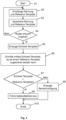
- Fig. 3 a description of an exemplary access control method as an aspect of a method for operating the access control system 1.
- the description is made with reference to a user 2 who wishes to enter the restricted access zone 8 at the entrance 12, for example to use an elevator there.
- the user 2 carries the mobile device 6 with him and has activated its radio module (e.g. for Bluetooth communication).
- a reference template for facial features of the user 2 is already stored in the mobile device 6.
- An associated software application is also activated.
- the method begins in a step S1 and ends in a step S10.
- the transceiver 14 receives a device-specific identifier transmitted by the mobile device 6 in a step S2.
- the transceiver 14 and the mobile device 6 communicate according to the same communication standard, in this embodiment via a radio connection according to a Bluetooth standard.
- the transceiver 14 also receives a reference template for facial parameters of the user 2.
- the identifier and the reference template can be sent essentially simultaneously or sequentially by the mobile device 6. In Fig. 3 the sending of the identifier and the reference template takes place in one (common) step (step S2). In another representation, the sending of the reference template could also take place in a separate step.
- the received identifier and the received reference template are stored in a step S3.
- the identifier and the reference template are stored, for example, as a data record in the buffer device 28.
- Steps S2 and S3 are carried out for each mobile device 6 that is within radio range of the transceiver 14 and operates according to the same communication standard as the transceiver 14.
- a plurality of identifiers and associated reference templates corresponding to a group of present users 2 can be stored in the buffer device 28 at a specific time.
- the person skilled in the art will recognize that the buffer device 28 is updated when a mobile device 6 is no longer within radio range, e.g. because the associated user 2 has left the public zone 10 without requesting access to the restricted access zone 8 or because the associated user 2 has already entered the restricted access zone 8.
- the buffer device 28 thus stores the data records for users 2 who are present in the public zone 10 at a specific time.
- a step S4 it is determined whether one of the users 2 present wishes to access the restricted access zone 8.
- the access control system 1 recognizes this wish according to an embodiment with the aid of the above-mentioned sensor module or the detection of background changes. For example, the sensor module detects when the user 2 enters the detection range of the camera 16, whereupon the camera 16 is activated. If an access wish is recognized, the method proceeds along the yes branch to a step S5. Otherwise, the method proceeds along the no branch back to step S2.
- step S5 the activated camera 16 generates a digital image depicting at least the face of the detected user 2, and the image processing module 22 generates a real-time template from the digital image, as described elsewhere in this description.
- step S6 the real-time template determined in step S5 is used to determine whether the real-time template can be assigned to a reference template stored in the buffer device 28.
- a step S7 checks whether the real-time template matches a reference template to a specified degree.
- the real-time template and the reference templates each comprise a specified number of specified facial parameters and their values (e.g. eye distance, mouth width, distance between the upper edge of the lip and the lower edge of the lip, distance between the nose and the lower edge of the lip, etc.).
- the parameter values of the real-time template are compared with the parameter values of the reference templates. A match exists if the degree of similarity of the templates is at least equal to the specified degree.
- the specified degree indicates a percentage match between the facial parameters of the real-time template and the facial parameters of a reference template. Depending on the accuracy requirement, the specified degree can be selected between approx. 60% and approx. 90%, for example.
- the method proceeds along the yes branch to a step S9 in which a user-specific building action is carried out for this user 2.
- the building action can, for example, consist of a destination call being triggered for user 2 (according to the data of the user profile existing for this user 2), an elevator being assigned to this destination call and the assigned elevator being displayed to user 2 at the entrance 12.
- the building action can also consist of one or more doors being unlocked to which this user 2 is authorized to access. The expert recognizes that these building actions can also be carried out in combination.
- the method proceeds along the no branch to a step S8 in which a notification is generated.
- the notification can, for example, inform the user 2 that an error has occurred and/or that the user 2 should contact a person responsible for the building (e.g. reception staff, security staff). Irrespective of this, the security staff can also be notified directly in step S8.
- the access control system 1 is connected to an elevator system connected, in particular with an elevator control system.
- the communication between the access control system 1 and the elevator control system can take place via the communication network 37.
- the access control takes place, for example, in the entrance hall of the building, which the users 2 have to pass through in order to get to the elevators
- a destination call can be initiated each time access is granted for the user 2 in question.
- the elevator control system of the elevator system processes the destination call and assigns him an elevator.
- the elevator assigned to the destination call can be displayed to the user 2, for example, by a terminal at the entrance 12 and/or communicated by voice. The user 2 can thus go directly to the assigned elevator without having to enter an elevator call.
- each user 2 is registered in the access control system 1 as an authorized user 2.
- non-registered users 2 may also wish to access the restricted zone 8, for example visitors.
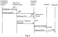
- Fig. 4 shows a signal diagram of an embodiment of a method that makes it possible to grant visitors convenient access to the restricted zone 8.
- Fig. 4 schematically shows interactions between a host or a host system 39 used by him, a visitor or his mobile device 6, the access control system 1, the camera 16 and a building system in order to register the visitor by means of a registration process in the control system 1, to enable access and to carry out a specified building action.
- the visitor is thus also a user 2 (the reference number 2 is used below for both the visitor and for one or more users).
- the host and the visitor 2 agree on an appointment, i.e. on a date and time or a period of time at which the host expects the visitor 2.
- the host then creates an invitation, for example using the host system 39 (e.g. PC, notebook, tablet PC, smartphone or another electronic device) and a software application installed on it (e.g. using Microsoft Outlook TM or similar application programs), and sends it to the visitor 2, for example via the communication network 37 and the communication connection 40.
- the communication connection 40 can, for example, via a mobile communications system.
- the invitation includes the appointment details, an identification number assigned to the invitation (in Fig. 4 referred to as "ID") and also information about a communication channel that the visitor 2 has to use to communicate with the access control system 1 for the purpose of registration.
- the communication channel is the Internet; the information about the communication channel therefore includes an Internet address for a web portal (in Fig. 4 referred to as a "link").
- the Internet address can, for example, comprise a uniform resource locator (URL) that identifies and locates the web portal as a resource via the access method to be used (e.g. a network protocol used such as HTTP or FTP) and the location of the resource in a computer network.
- the web portal is associated with a computer system of the access control system 1.
- the invitation is transmitted via the communication network 37 by means of a signal DS1; it can, for example, be sent as a text message to the mobile device 6 of the visitor 2 or as an email to the email address of the visitor 2.
- the host or host system 39 also sends the invitation data to the access control system 1 using a signal DS2, for example via the communications network 37 and essentially at the same time as the invitation is sent or at a later time.
- the access control system 1 creates a visitor profile for the received invitation data, for example controlled by the processor 20.
- the invitation data includes not only the appointment details but also details about the host, for example name, telephone number, floor and/or apartment or office number, and the visitor (for example name).
- a time window can be specified within which the visitor 2 is to be granted access. The time window can, for example, specify that the visitor 2 is granted access approximately half an hour before and after the start of the appointment in the event that the visitor 2 arrives too early or is late.
- the visitor profile can be deleted after the visitor 2 arrives or at a later time.
- Visitor 2 accepts the invitation, the communication channel specified in the invitation is used to send the invitation identification number and the Identifier of the mobile device 6 to the access control system 1. Depending on the design, the visitor can be asked to enter the identifier of the mobile device 6 (for example telephone number or device identification number). If the visitor accepts the invitation using the mobile device 6, in one embodiment the identifier of the mobile device 6 is also transmitted to the access control system 1, e.g. automatically. If an application-specific software application is installed on the mobile device 6, as described above, it supports the visitor 2 in accepting the invitation. The identifier and the identification number of the invitation are transmitted using a signal DS3, for example via the communication network 37 and the communication connection 40.
- a signal DS3 for example via the communication network 37 and the communication connection 40.
- the signal DS3 can be transmitted according to a known transmission protocol, for example TCP (Transmission Control Protocol), IP (Internet Protocol) and UDP (User Data Protocol).
- TCP Transmission Control Protocol
- IP Internet Protocol
- UDP User Data Protocol
- the invitation can ask the visitor 2 to transmit the ID and the identification number of the invitation to a building management office.
- the building management office can, for example, manage the database 34 for the building in question, in which the user profiles of the users 2 with access authorization are stored.
- the transmission to the building management office can, for example, be made to an email address of the building management office or telephone number of the building management office specified in the invitation, for example for an SMS or MMS message. Building management staff can then arrange for the received data to be further processed.
- the invitation also asks the visitor to take a self-portrait (also known as a "selfie") of themselves, e.g. with the camera of their mobile device 6, and to save it on the mobile device 6.
- a self-portrait also known as a "selfie”
- An advantage of the technology described here is that the visitor 2 can create the selfie at a time of their choosing, as long as this is done before the appointment.
- the visitor 2 can be geographically far away from the building or already in or near the building.
- the application-specific software application installed on the mobile device 6 supports the Visitor 2 also creates and saves the self-portrait as a reference template of Visitor 2.
- visitor 2 can be assigned the following according to the Fig. 3 described access control procedure, the specified building action is carried out when he arrives in the building at the agreed time.
- the transceiver 14 receives the identifier transmitted by the mobile device 6 and the reference template.
- the reception of the identifier of the mobile device 6 and the reference template takes place as described above and is in Fig. 4 by means of a signal DS4.
- the camera 16 If the visitor then comes into the detection range of the camera 16, the camera 16 generates a digital image that shows the visitor's face.
- the generation of the digital image by the camera 16 and the subsequent generation of a real-time template are carried out as described above; in Fig. 4 This is represented by a signal DS5.
- the access control system 1 checks whether the real-time template matches the reference template to a specified degree. In addition, the access control system 1 checks whether the visitor requests access within the time window specified in the visitor profile. If both conditions are met, the visitor is granted access and the building action is initiated; in Fig. 4 This is represented by a signal DS6.
- the access control system 1 can communicate with an elevator control in order to generate a destination call for visitor 2 when access is granted as an example building action.
- the elevator control assigns an elevator to the destination call, whereby the assigned elevator can be communicated to visitor 2 in the area of the access 12 by display or voice.
- the assigned elevator transports visitor 2 to the floor on which the host is located.
- the host's floor is stored, for example, in the visitor profile in connection with the invitation data. Visitor 2, especially if he is in the building for the first time, therefore does not need to concern himself with entering the destination floor.
- Visitor 2 can also be provided with further information to enable him to orient himself better in the building, for example visitor 2 can be informed in which direction (possibly also how far) he should go after the Alighting on the floor.
- the communication of such guidance information can be carried out, for example, by means of the mobile device 6 of the visitor 2 and/or displays on the floors or in the elevator car.
- the access control system 1 generates and sends a message for the host informing the host that the visitor has been granted access. The host can thus prepare promptly for the visitor's arrival.
Landscapes
- Engineering & Computer Science (AREA)
- Physics & Mathematics (AREA)
- General Physics & Mathematics (AREA)
- Human Computer Interaction (AREA)
- Health & Medical Sciences (AREA)
- General Health & Medical Sciences (AREA)
- Oral & Maxillofacial Surgery (AREA)
- Multimedia (AREA)
- Theoretical Computer Science (AREA)
- Lock And Its Accessories (AREA)
- Telephonic Communication Services (AREA)
- Alarm Systems (AREA)
Description
- Die hier beschriebene Technologie betrifft allgemein ein Zugangskontrollsystem, das einem berechtigten Nutzer Zugang zu einer zugangsbeschränkten Zone in einem Gebäude oder einem Gelände gewährt. Ausführungsbeispiele der Technologie betreffen insbesondere ein Zugangskontrollsystem mit einer Sende- und Empfangseinrichtung und ein Verfahren zum Betreiben eines solchen Zugangskontrollsystems. Zugangskontrollsysteme können auf verschiedenste Art und Weise ausgestaltet sein. Die Ausgestaltungen können beispielsweise die Art betreffen, wie sich Nutzer (Personen) als zugangsberechtigt auszuweisen haben, z. B. mit einem Schlüssel, einer Magnet-, Chip- oder RFID Karte oder einem mobilen elektronischen Gerät (z. B. Mobiltelefon).
WO 2010/112586 A1 beschreibt ein Zugangskontrollsystem, bei dem ein von einem Nutzer mitgeführtes Mobiltelefon einen Identifikationscode an einen Zugangsknoten sendet. - Falls der Identifikationscode als gültig erkannt wird, sendet der Zugangsknoten einen Zugangscode an das Mobiltelefon, das den Zugangscode auf einer Anzeige dargestellt. Hält der Nutzer das Mobiltelefon an eine Kamera, so dass diese den dargestellten Zugangscode erfassen kann, überprüft das Zugangskontrollsystem, ob der erfasste Zugangscode gültig ist. Ist er gültig, wird dem Nutzer der Zugang gewährt. Dieses Zugangskontrollsystem bietet eine gewisse Benutzerfreundlichkeit, weil die Nutzer keine Berechtigungsausweise oder herkömmliche Schlüssel bei sich tragen und sich keinen Zugangscode merken müssen. Stattdessen bietet das mobile elektronische Gerät, das viele Nutzer für Kommunikationszwecke sowieso bereits bei sich tragen, die Funktion eines Berechtigungsausweises oder Schlüssels.
- Bei diesen Zugangskontrollsystemen ist es erforderlich, dass die Nutzer mit den Schlüsseln, Karten oder mobilen Geräten hantieren. Vor allem in Bereichen eines Gebäudes mit hohem Personenverkehrsaufkommen, z. B. in einer Eingangshalle, kann ein solches Hantieren umständlich sein und den Personenfluss behindern. Es besteht daher Bedarf an einer anderen, noch benutzerfreundlicheren Technologie.
- Die
US 2015/221151 A1 beschreibt ein auf Gesichtserkennung basierendes Zugangskontrollsystem und -verfahren, bei dem auf Basis einer empfangenen Gerätekennung ein biometrisches Referenz-Template aus einer Datenbank ausgelesen wird. - Ein Aspekt der vorliegenden Erfindung betrifft ein Verfahren nach Anspruch 1.
- Ein anderer Aspekt der vorliegenden Erfindung betrifft ein System nach Anspruch 10.
- Die hier beschriebene Technologie schafft ein Zugangskontrollsystem, bei dem kein Hantieren mit dem mobilen elektronischen Gerät durch den Nutzer erforderlich ist, insbesondere dann nicht, wenn der Nutzer bereits am oder nahe des Zugangs (z. B. einer Schleuse oder Barriere) ist. Eine erste Phase einer Überprüfung, ob der Nutzer zugangsberechtigt ist, erfolgt bereits wenn der Nutzer noch relativ weit vom Zugang entfernt ist. Der Nutzer kann sich beispielsweise in Richtung des Zugangs zur zugangsbeschränkten Zone bewegen, währenddessen in einem Ausführungsbeispiel das mobile elektronische Gerät des Nutzers schon in Kommunikation mit der Sende- und Empfangseinrichtung des Zugangskontrollsystems ist oder bereits war. Die Sende- und Empfangseinrichtung empfängt die Kennung des mobilen elektronischen Geräts und das Referenz-Template des Nutzers. Ist der Nutzer im Zugangskontrollsystem als zugangsberechtigt registriert, ist für den Nutzer ein Nutzerprofil gespeichert. Kommt der Nutzer in einen Erfassungsbereich einer Kamera des Zugangskontrollsystems, werden in einer zweiten Phase aus einer Kameraaufnahme Gesichtsmerkmale des Nutzers ermittelt und als Echtzeit-Template definiert. Stimmt das Echtzeit-Template mit einem gespeicherten Referenz-Template zu einem festgelegten Grad überein, ist der Nutzer erkannt und es kann für den Nutzer eine Gebäudeaktion veranlasst werden, ohne dass der Nutzer mit dem mobilen elektronischen Gerät hantieren muss. Ein berechtigter Nutzer kann somit quasi nahtlos in die zugangsbeschränkte Zone gelangen und die Gebäudeaktion in Anspruch nehmen.
- Die hier beschriebene Technologie schafft ausserdem ein Zugangskontrollsystem, bei dem keine zentrale Speicherung von Gesichts-Templates in einem z. B. für längere Zeit (z. B. Monate oder Jahre) angelegten Nutzerprofil erfolgt. Das Referenz-Template eines Nutzers ist auf dem mobilen Gerät des Nutzers gespeichert (und unterliegt damit der Kontrolle des Nutzers) und wird nur dann zum Zugangskontrollsystem übermittelt, wenn der Nutzer tatsächlich vor Ort ist, z. B. um in einem Gebäude eine zugangsbeschränkte Zone betreten und eine Gebäudeaktion nutzen zu können. Selbst in diesem Fall wird das Referenz-Template im Zugangskontrollsystem nur solange temporär gespeichert, bis der Nutzer entweder Zugang erhält oder sich wieder ausserhalb der Funkreichweite befindet.
- Die Technologie trägt somit dazu bei, die Interessen eines Nutzers bezüglich Datenschutz und Wahrung der Privatsphäre angemessen zu berücksichtigen.
- Zu einer zugangsbeschränkten Zone in einem Gebäude oder einem Gebiet kann eine grosse Anzahl von Nutzern (z. B. mehrere Dutzend oder Hundert) zugangsberechtigt sein. In einer solchen Situation empfängt die Sende-und Empfangseinrichtung eine Vielzahl von Kennungen und Referenz-Templates, die in der Speichereinrichtung als Datensätze gespeichert werden. Trotzdem bietet die hier beschriebene Technologie den Vorteil, dass die Überprüfung auf Übereinstimmung schnell erfolgt, weil das vor Ort erzeugte Echtzeit-Template nur mit den Referenz-Templates der tatsächlich anwesenden Nutzer auf Übereinstimmung überprüft wird. Ein anwesender Nutzer kann somit ohne wesentliche Stockung oder Verzögerung in die zugangsbeschränkte Zone gelangen. Dies reduziert vor allem bei hohem Verkehrsaufkommen das Risiko, dass sich vor dem Zugang eine Warteschlange bildet.
- Die Technologie bietet nicht nur eine schnellere Überprüfung, sie kann auch bei hohen Anforderungen an die Sicherheit eingesetzt werden, weil beispielsweise eine Authentifizierung über eine gesicherte (verschlüsselte) Funkverbindung erfolgt. Die per Funk übertragene Kennung muss im System zu einem registrierten Nutzer gehören; dadurch kann der Nutzer erkannt und die für den Nutzer festgelegten Rechte (z. B. Zugangsrechte) können ermittelt werden. Neben der Funkverbindung wird als ein weiterer Kanal die optische Erfassung des Gesichts des Nutzers genutzt. Durch diesen optischen Kanal kann erkannt werden, welcher der möglicherweise zahlreichen anwesenden Nutzer tatsächlich Zugang wünscht, so dass nur diesem Nutzer Zugang gewährt und die für diesen Nutzer festgelegte Gebäudeaktion ausgeführt wird.
- Die Technologie reduziert auch den Aufwand zum Verwalten der Nutzerprofile. Da die Referenz-Templates nicht zentral gespeichert werden, ist es z. B. auch nicht erforderlich, diese zu aktualisieren, wenn sich beispielsweise das Aussehen eines Nutzers nach einiger Zeit verändert hat. Um die Speicherung des (aktuellen) Referenz-Templates auf dem mobilen Gerät kümmert sich jeder Nutzer selbst. Vor der erstmaligen Nutzung eines mobilen Geräts gemäss der hier beschriebenen Technologie erzeugt der Nutzer ein Bild von sich selbst, das als ein Referenz-Template im mobilen Gerät gespeichert wird. Danach kann jeder Nutzer z. B. in regelmässigen Abständen daran erinnert werden, ein neues (aktuelles) Bild von sich zu machen. Dadurch wird erreicht, dass das Echtzeit-Template eines Nutzers zu einem hohen Mass mit dem Referenz-Template des Nutzers übereinstimmt.
- Bei der hier beschriebenen Technologie ist zum einen die Überprüfung auf Übereinstimmung auf eine begrenzte Menge von Referenz-Templates beschränkt. Zum anderen erfolgt die Authentifizierung eines Nutzers basierend auf der empfangenen Kennung, die im Fall eines zugangsberechtigten Nutzers einem gespeicherten Nutzerprofil zugeordnet ist. Für die Bildverarbeitungseinrichtung bedeutet dies, dass an einen darin implementierten Bildverarbeitungsalgorithmus relativ geringe Anforderungen gestellt werden, beispielsweise hinsichtlich Erkennungsgenauigkeit. Im Vergleich zu einem Bildverarbeitungsalgorithmus, dessen Aufgabe es ist, eine Person aufgrund von relativ vielen Gesichtsmerkmalen mit einer hohen Erkennungsgenauigkeit zu identifizieren (d. h., der Grad der Übereinstimmung muss relativ hoch sein, beispielsweise größer ca. 90 %), genügt es bei der hier beschriebenen Technologie, relativ wenig Gesichtsmerkmale einem Referenz-Template eines anwesenden Nutzers zuzuordnen. Außerdem kann der Grad der Übereinstimmung zum Beispiel auf zwischen ca. 60 % und ca. 90 % festgelegt werden. Es kann daher ein kostengünstiger Bildverarbeitungsalgorithmus verwendet werden; die Anforderungen an die Sicherheit können aber trotzdem gewährleistet werden.
- Erfindungsgemäß umfasst das Prüfen auf Übereinstimmung ein Erzeugen eines Ergebnissignals. Bei Übereinstimmung wird ein Ausführen einer Gebäudeaktion veranlasst. Die Gebäudeaktion ist spezifisch für den erkannten Nutzer. Um diese Gebäudeaktion zu ermitteln, wird ein in der Speichereinrichtung gespeichertes Nutzerprofil des erkannten Nutzers gelesen; dort kann beispielsweise das Stockwerk angegeben sein, zu dem der Nutzer zugangsberechtigt ist. Die nutzerspezifische Gebäudeaktion kann ein Entriegeln einer Gebäudetür (z. B. Büro- oder Wohnungstür einschliesslich einer oder mehrerer Türen, die sich auf dem Weg vom Zugang zur Büro- oder Wohnungstür befinden) umfassen. In Verbindung mit einer Aufzugsanlage kann die nutzerspezifische Gebäudeaktion auch ein Registrieren eines Zielrufs auf ein für den Nutzer festgelegtes Zielstockwerk umfassen. Dadurch wird die Benutzerfreundlichkeit verbessert, weil der Nutzer direkt zu einer zugeteilten Aufzugskabine gehen kann, ohne selbst einen Aufzugsruf eingeben zu müssen. Die nutzerspezifische Gebäudeaktion kann auch eine Kombination aus dem Entriegeln einer Gebäudetür und dem Registrieren eines Zielrufs umfassen.
- Ausserdem gibt das Ergebnissignal an, dass der Nutzer Zugang zur zugangsbeschränkten Zone hat, während es bei Nichtübereinstimmung angibt, dass der Nutzer keinen Zugang zur zugangsbeschränkten Zone hat. Als Funktion des Ergebnissignals kann in einem Ausführungsbeispiel ein Steuersignal erzeugt werden, um eine (physische) Barriere (z. B. Schranke, Tür oder Drehkreuz) freizugeben. Eine nicht freigegebene Barriere bleibt blockiert. In einem anderen Ausführungsbeispiel aktiviert das Steuersignal bei einer Zugangsverwehrung eine Informationseinrichtung. Die Informationseinrichtung kann z. B. in Verbindung mit einem Zugang ohne eine physische Barriere eingesetzt werden. Wird ein unberechtigter Nutzer am Zugang erkannt, kann in einem Fall die Informationseinrichtung einen Alarm erzeugen, der am Zugang wahrnehmbar (akustisch und/oder visuell) ist. Das Steuersignal kann in einem anderen Fall einen Sicherheitsdienst alarmieren, der daraufhin den als nicht zugangsberechtigt erkannten Nutzer überprüft.
- In einem Ausführungsbeispiel erfolgt die Funkverbindung zwischen der Sende- und Empfangseinrichtung und einem mobilen elektronischen Gerät eines Nutzers gemäss einem Bluetooth-Standard oder einem WLAN/WiFi-Standard. Dies ist von Vorteil, weil handelsübliche Mobiltelefone oder Smartphones bereits mit Technologie gemäss einem dieser Standards ausgestattet sind und somit keine speziellen Geräte benötigt werden.
- Die hier beschriebene Technologie ermöglicht auch Flexibilität bezüglich der Kennung eines mobilen Geräts. Die Kennung eines mobilen Geräts kann beispielsweise eine dem Gerät fest zugeordnete Geräteidentifikationsnummer oder eine dem mobilen Gerät zugeordnete Telefonnummer umfassen. In einem Ausführungsbeispiel ist jedes mobile Gerät mit einer anwendungsspezifischen Software ausgestattet, die eine für das mobile Gerät einzigartige und zeitlich unveränderliche Kennung erzeugt. Die Kennung (unabhängig davon, ob sie eine Geräteidentifikationsnummer oder eine Telefonnummer umfasst oder durch Software erzeugt ist) ermöglicht die eindeutige Identifikation eines mobilen Geräts.
- In einem Ausführungsbeispiel ist die Bildverarbeitungseinrichtung modular aufgebaut; ein Bildverarbeitungsmodul erzeugt aus einer Kameraaufnahme das Echtzeit-Template, und ein Auswertemodul, das mit dem Bildverarbeitungsmodul und der Speichereinrichtung verbunden ist, erzeugt ein Ergebnissignal, das angibt, ob das Echtzeit-Template mit einem Referenz-Template übereinstimmt. Eine solche Modularität erlaubt eine effiziente Anpassung der Module an unterschiedliche Anforderungen (z. B. Implementierung eines kostengünstigen Bildverarbeitungsalgorithmus im Auswertemodul).
- Modularität ist in einem Ausführungsbeispiel auch bezüglich eines Prozessors gegeben, der mit der Bildverarbeitungseinrichtung verbunden ist. Abhängig vom Ergebnissignal erzeugt der Prozessor ein Steuersignal, um ein Lesen eines in der Speichereinrichtung gespeicherten Nutzerprofils des erkannten Nutzers zu veranlassen, um daraufhin eine nutzerspezifische Gebäudeaktion zu veranlassen. Der Prozessor steuert das Zugangskontrollsystem zudem so, dass dem Nutzer Zugang gewährt oder verwehrt wird.
- Im Folgenden sind verschiedene Aspekte der verbesserten Technologie anhand von Ausführungsbeispielen in Verbindung mit den Figuren näher erläutert. In den Figuren haben gleiche Elemente gleiche Bezugszeichen. Es zeigen:
- Fig. 1
- eine schematische Darstellung eines Anwendungsbeispiels eines Zugangskontrollsystems in Verbindung mit einem Gebäude;
- Fig. 2
- eine schematische Darstellung eines Ausführungsbeispiels eines Zugangskontrollsystems;
- Fig. 3
- ein Ablaufdiagram eines Ausführungsbeispiels eines Zugangskontrollverfahrens als ein Aspekt eines Verfahrens zum Betreiben des Zugangskontrollsystems; und
- Fig. 4
- ein beispielhaftes Signaldiagramm zur Darstellung eines Ausführungsbeispiels eines Besucher-Registrierungsverfahrens als ein Aspekt eines Verfahrens zum Betreiben des Zugangskontrollsystems.
-
Fig. 1 ist eine schematische Darstellung eines Anwendungsbeispiels eines Zugangskontrollsystems 1 in Verbindung mit einer Situation in einem Gebäude, von dem aus Darstellungsgründen lediglich einige Wände, Räume 4 und Zonen 8, 10 gezeigt sind. Die Räume 4 können z. B. Büros, Wohnungen, Hallen und/oder Aufzugskabinen eines Aufzugsystems sein. In der inFig. 1 gezeigten Anwendung des Zugangskontrollsystems 1 befinden sich in der Zone 10 mehrere Nutzer 2, die mobile elektronische Geräte 6 (im Folgenden auch als mobile Geräte 6 bezeichnet), mit sich führen. Die Zone 10 unterliegt in diesem Beispiel keiner Zugangsbeschränkung und wird im Folgenden auch als öffentliche Zone 10 bezeichnet. Die öffentliche Zone 10 kann ein Bereich im oder ausserhalb des Gebäudes sein. Ein Zugang 12 trennt die öffentliche Zone 10 von der Zone 8, die einer Zugangsbeschränkung unterliegt und an die Räume 4 angrenzt. Der Fachmann erkennt, dass das Zugangskontrollsystem 1 nicht auf Anwendungen innerhalb eines Gebäudes beschränkt ist, sondern in analoger Weise auch zur Kontrolle des Zugangs zu einer zugangsbeschränkten Zone auf einem Gelände verwendet werden kann. Unter dem Begriff "Gebäude" sind in dieser Beschreibung z. B. Wohngebäude, Geschäftsgebäude, Sportarenen, Einkaufszentren, aber auch Schiffe zu verstehen. - Das Zugangskontrollsystem 1 überwacht den Zugang 12, sodass nur berechtigte Nutzer 2 in die Zone 8 gelangen können, beispielsweise durch Blockieren oder Freigeben einer Tür, einer Schranke, eines Drehkreuzes, oder einer anderen physischen Barriere oder Schleuse, durch Ansteuern (z. B. Aktivieren) einer Informationseinrichtung 38 im Fall eines Zugangs ohne physische Barriere, wenn ein unberechtigter Nutzer 2 erkannt wird, oder durch Kombinieren dieser Massnahmen. Die Informationseinrichtung 38 kann z. B. einen optischen und/oder akustischen Alarm auslösen oder eine Benachrichtigung eines Sicherheitsdienstes veranlassen. In
Fig. 1 ist das Zugangskontrollsystem 1 zur Veranschaulichung als im Zugang 12 angeordnet eingezeichnet. Je nachdem für welches Verkehrsaufkommen das Zugangskontrollsystem 1 vorgesehen ist, besteht der Zugang 12 aus mehreren einzelnen Schleusen; inFig. 1 kann z. B. jedes der beiden Drehkreuze 36 eine Schleuse darstellen. Der Fachmann erkennt, dass in einer konkreten Implementierung das Zugangskontrollsystem 1 bzw. seine Komponenten auf verschiedene Art und Weise angeordnet sein können. - Die in
Fig. 1 dargestellten Räume 4 können beispielsweise zu einer Gruppe von Aufzügen gehören, die z. B. sechs Aufzüge (A-F) umfasst. Wird ein Nutzer 2 am Zugang 12 erkannt, bedeutet dies in einem Ausführungsbeispiel, dass der Nutzer 2 mit einem der Aufzüge auf ein für diesen Nutzer 2 festgelegtes Zielstockwerk transportiert werden möchte. Mit dem Erkennen des Nutzers 2 wird ein Zielruf veranlasst, dem eine Aufzugssteuerung einen Aufzug zuweist. Der zugewiesene Aufzug wird dem Nutzer 2 mitgeteilt, beispielsweise mittels einer Anzeigeeinheit. In der inFig. 1 gezeigten Situation kann jedem Drehkreuz 36 jeweils eine Anzeigeeinheit zugeordnet sein. Nutzt der Nutzer 2 beispielsweise eines der inFig. 1 gezeigten Drehkreuze 36, erkennt das Zugangskontrollsystem 1, an welchem Drehkreuz 36 sich der Nutzer 2 befindet und steuert die dort angeordnete Anzeigeeinheit an, um den zugeteilten Aufzug (z. B. "A") anzuzeigen. - Wie in
Fig. 1 angedeutet, umfasst das Zugangskontrollsystem 1 eine Sende- und Empfangseinrichtung 14 (inFig. 1 als TX/RX dargestellt) und eine Kamera 16 als Teil einer Bildverarbeitungseinrichtung; weitere Komponenten des Zugangskontrollsystem 1 sind inFig. 2 gezeigt. Erfindungsgemäß ist die Sende- und Empfangseinrichtung zum Empfang von Funksignalen ausgestaltet, sie ist im Folgenden auch als Transceiver 14 bezeichnet. Der Transceiver 14 kommuniziert mit den mobilen elektronischen Geräten 6, wenn sie sich in Funkreichweite zum Transceiver 14 befinden, d. h. ein von einem mobilen Gerät 6 ausgesendetes Funksignal hat am Ort des Transceivers 14 eine Signalstärke (beispielsweise ausgedrückt durch einen RSSI-Wert (Received Signal Strength Indicator)), die grösser als ein für einen sicheren Empfang festgelegter Schwellenwert ist. Die Kommunikation erfolgt beispielsweise über ein Nahfeld-Funknetz wie z. B. ein Bluetooth-Funknetz, WLAN/WiFi- oder ein ZigBee-Funknetz. Bluetooth ist ein Standard gemäss IEEE 802.15.1, WLAN/WiFi ist ein Standard gemäss IEEE 802.11, Zig-Bee ist ein Standard gemäss IEEE 802.15.4; solche Funknetze gemäss diesen Standards dienen der kabellosen Vernetzung von Geräten über eine kurze Distanz von ca. einigen Metern bis ca. hundert Meter. Das Funknetz bildet dabei die Schnittstelle, über die das mobile elektronische Gerät 6 und der Transceiver 14 miteinander kommunizieren können. - In der in
Fig. 1 gezeigten Situation ist die hier beschriebene Technologie in vorteilhafter Weise anwendbar, um das Zugangskontrollsystem 1 mit möglichst geringer Komplexität zu betreiben und dem Nutzer 2 komfortabel Zugang zur zugangsbeschränkten Zone 8 zu gewähren. Kurz und beispielhaft zusammengefasst erfolgt der Betrieb des Zugangskontrollsystems 1 gemäss einem Ausführungsbeispiel wie folgt: Sobald ein Nutzer 2 in Funkreichweite zum Transceiver 14 ist, kommuniziert sein mobiles Gerät 6 über eine Funkverbindung automatisch mit dem Transceiver 14 und das mobile Gerät 6 sendet seine gerätespezifische Kennung zum Transceiver 14. Das mobile Gerät 6 sendet ausserdem Gesichtsparameter des Nutzers 2 in Form eines elektronischen Referenz-Templates zum Transceiver 14. In der Situation gemässFig. 1 empfängt der Transceiver 14 eine Vielzahl von Kennungen und Referenz-Templates. Das Zugangssystem 1 "weiss" daher, wie viele mobile Geräte 6 sich zu einem bestimmten Zeitpunkt in Funkreichweite befinden und, wenn deren Nutzer 2 für das Gebäude registrierte Nutzer 2 sind, zu welchen Nutzern 2 die mobilen Geräte 6 gehören. Zu diesem Zeitpunkt kann das Zugangskontrollsystem 1 für jeden registrierten Nutzer 2 prüfen, welche Rechte für den Nutzer im Gebäude festgelegt sind (z. B. Zutrittsberechtigung zu einem oder mehreren Räumen 4 und/oder Stockwerken, einschliesslich evtl. zeitlicher Beschränkungen). - Die so erfassten Nutzer 2 stellen eine Gruppe von anwesenden Nutzern 2 dar. Möchte nun einer der anwesenden Nutzer 2 Zugang zur zugangsbeschränkten Zone 8, bewegt sich der Nutzer 2 in Richtung des Zugangs 12, was vom Zugangskontrollsystem 1 erkannt wird. Das Zugangskontrollsystem 1 ermittelt im Rahmen eines Bildverarbeitungs- bzw. Gesichtserkennungsverfahrens einen Datensatz mit Gesichtsmerkmalen (Echtzeit-Template) dieses Nutzers 2 und vergleicht dieses Echtzeit-Template mit den gespeicherten Referenz-Templates, die den anwesenden Nutzern 2 zugeordnet sind. Dieser Vergleich ist auf die Gruppe der anwesenden Nutzer 2 beschränkt; es werden somit nur die Datensätze dieser Gruppe daraufhin durchsucht, ob der ermittelte Datensatz zu einem der gespeicherten Datensätze passt. Dadurch kann erkannt werden, welcher der anwesenden Nutzer 2 zu diesem Zeitpunkt tatsächlich Zugang wünscht und welche Rechte dieser Nutzer 2 hat. Für diesen Nutzer 2 kann beispielsweise eine in einem Nutzerprofil festgelegte Gebäudeaktion veranlasst werden; für den Nutzer 2 können beispielsweise ein Zielruf registriert und daran anschliessend ein Aufzug zugeteilt werden, der den Nutzer 2 auf das Stockwerk transportiert, auf dem sich der Arbeitsplatz des Nutzers 2 befindet.
-
Fig. 1 zeigt ausserdem ein Kommunikationsnetzwerk 37, das in einem Ausführungsbeispiel mit einem Gastgebersystem 39 und dem Zugangskontrollsystem 1 kommunikativ verbunden ist. Ausserdem ist angedeutet, dass ein Nutzer 2 über das Kommunikationsnetzwerk 37 mittels einer Kommunikationsverbindung 40 kommunizieren kann, beispielsweise mit dem Gastgebersystem 39 oder einem Webportal. Beispielhafte Anwendungen des Kommunikationsnetzwerks 37 und des Gastgebersystems 39 sind in Verbindung mitFig. 4 beschrieben. -
Fig. 2 zeigt eine schematische Darstellung eines Ausführungsbeispiels des Zugangskontrollsystems 1. Das Zugangskontrollsystem 1 ist in einem Ausführungsbeispiel modular aufgebaut und umfasst eine Bildverarbeitungseinrichtung, die neben der Kamera 16 ein Bildverarbeitungsmodul 22 (Bildverarbeitung inFig. 2 ) und ein Auswertemodul 24 (Auswertung inFig. 2 ) umfasst. Zusätzlich umfasst das Zugangskontrollsystem 1 den Transceiver 14, einen Prozessor 20, eine Speichereinrichtung 26 (Speicher inFig. 2 ) und eine Zwischenspeichereinrichtung 28 (Zwischenspeicher inFig. 2 ). Der Fachmann erkennt, dass mindestens eine der Speichereinrichtungen 26, 28 auch der Bildverarbeitungseinrichtung zugeordnet werden kann oder dass die Funktion der Zwischenspeichereinrichtung 28 durch die Speichereinrichtung 26 wahrgenommen werden kann und somit die Zwischenspeichereinrichtung 28 in einem Ausführungsbeispiel entfallen kann. - Der Prozessor 20 hat einen Ausgang 32 für ein Steuersignal und einen Eingang 30 für ein vom Auswertemodul 24 erzeugtes Ergebnissignal. Abhängig vom Ergebnissignal steuert der Prozessor 20 das Zugangskontrollsystem 1 so, dass dem Nutzer 2 Zugang gewährt oder verwehrt wird. Bei Zugangsgewährung kann beispielsweise auch ein Zielruf veranlasst werden, und der diesem Zielruf zugeteilte Aufzug kann dem Nutzer 2 angezeigt werden. Trennt beispielsweise eine physische Barriere (z. B. Drehkreuz 36 in
Fig. 1 ) die Zonen 8, 10, gibt das Steuersignal die Barriere frei (beispielsweise in Verbindung mit der Anzeige des zugeteilten Aufzugs) oder blockiert diese. Erfolgt die Zonentrennung dagegen ohne eine physische Barriere, steuert das Steuersignal im Fall eines unberechtigten Nutzers 2 beispielsweise die Informationseinrichtung 38 für eine Alarmerzeugung an oder alarmiert einen Sicherheitsdienst. Die Informationseinrichtung 38 kann auch angesteuert werden, um in Verbindung mit einer Barriere dem Nutzer 2 oder einem Sicherheitsdienst anzuzeigen, dass die Barriere freigegeben oder blockiert wurde. - Die Kamera 16 erzeugt eine Kameraaufnahme eines Nutzers 2 (insbesondere dessen Gesicht), der sich im Erfassungsbereich der Kamera 16 befindet, wenn der Nutzer 2 am Zugang 12 die zugangsbeschränkte Zone 8 betreten möchte. In einem Ausführungsbeispiel umfasst die Kamera 16 eine Digitalkamera mit auswählbaren und/oder einstellbaren Eigenschaften; Kameraaufnahmen liegen in diesem Ausführungsbeispiel somit als digitale Datensätze (digitale Kameraaufnahme (auch als Digitalbild bezeichnet)) vor. Die Eigenschaften der Digitalkamera, zum Beispiel Auflösung (z. B. in Megapixel angegeben), Belichtung und Brennweite, sind so gewählt bzw. eingestellt, dass eine Kameraaufnahme (Digitalbild) auswertbar ist und das Gesicht des Nutzers 2 in auswertbarer Qualität auf dem Digitalbild erkennbar ist. Das Digitalbild liegt beispielsweise in einem JPEG Format vor, es kann aber auch in einem anderen Format vorliegen, beispielsweise im BMP oder JPEG2000 Format.
- Die Kamera 16 kann mit einem Sensormodul ausgestattet oder mit einem separaten Sensormodul verbunden sein, das die Kamera 16 aktiviert, wenn es die Anwesenheit eines Nutzers 2 im Erfassungsbereich der Kamera 16 detektiert. Das Sensormodul kann beispielsweise einen Näherungssensor umfassen, der als ein Ultraschallsensor, ein Infrarotsensor oder ein optischer Sensor (z. B. Lichtschranke, Helligkeitssensor) ausgestaltet sein kann. Alternativ dazu kann in einem Ausführungsbeispiel die Anwesenheit eines Nutzers 2 im Erfassungsbereich der Kamera 16 dadurch erkannt werden, dass Änderungen im Erfassungsbereich detektiert werden. Tritt der Nutzer 2 beispielsweise in den Erfassungsbereich und ist die Kamera 16 kontinuierlich in einem aktiven Zustand, zeichnet die Kamera 16 Änderungen vor einem im Wesentlichen statischen Hintergrund auf; diese Änderungen werden als Anwesenheit interpretiert.
- Der Transceiver 14 und die Kamera 16 (einschliesslich anderer Komponenten der Bildverarbeitungseinrichtung) können in einem Gehäuse, das z. B. wie in
Fig. 1 gezeigt im Zugang 12 angeordnet ist, angeordnet sein. Alternativ dazu können der Transceiver 14 und die Kamera 16 (einschliesslich anderer Komponenten der Bildverarbeitungseinrichtung) auch getrennt voneinander als separate Einheiten angeordnet sein, beispielsweise räumlich voneinander getrennt in einem Bereich um den Zugang 12, wobei die Kamera 16 so anzuordnen ist, dass im Wesentlichen nur derjenige Nutzer 2 erfasst wird, der auch tatsächlich Zugang wünscht. Je nach Ausgestaltung des Zugangskontrollsystems 1 können mehrere Kameras 16 vorhanden sein, beispielsweise kann jeder Barriere (z. B. Drehkreuz 36) eine Kamera 16 zugeordnet sein. - Das Auswertemodul 24 ist zur Veranschaulichung als separate Einheit gezeigt, die mit dem Bildverarbeitungsmodul 22, dem Prozessor 20 und der Zwischenspeichereinrichtung 28 verbunden ist. In einem Ausführungsbeispiel bilden das Auswertemodul 24 und das Bildverarbeitungsmodul eine Einheit. Die Speichereinrichtungen 26, 28 sind ebenfalls zur Veranschaulichung als separate Einheiten gezeigt; je nach Ausgestaltung können sie in einer Speichereinrichtung zusammengefasst sein, wo sie beispielsweise getrennte Speicherbereiche belegen. Unabhängig davon können die Speichereinrichtungen 26, 28 beispielsweise ein Festplatten (HDD)- oder CD/DVD-Laufwerk, ein Halbleiterlaufwerk/Solid-State-Disk (SSD), oder Kombinationen davon, oder andere Speichereinrichtungen für digitale Daten umfassen.
- Die genannte Einheit aus Auswertemodul 24 und Bildverarbeitungsmodul 22 umfasst mindestens eine Prozessoreinheit, die ein computergestütztes Verfahren zur Bildverarbeitung ausführt. Bildverarbeitungsverfahren sind bekannt, beispielsweise aus
US 8,494,231 B2 . Eine grundsätzliche Darstellung der Bildverarbeitung zum Zweck der Gesichtserkennung ist in der Veröffentlichung "Gesichtserkennung" des deutschen Bundesamts für Sicherheit in der Informationstechnik (unter dem Thema Biometrie verfügbar unter der Internet-Adresse www.bsi.bund.de) beschrieben. Diese Veröffentlichung unterscheidet zwischen den drei Hauptarbeitsschritten "Template erzeugen", "Referenzdatensatz erzeugen" und "Gesichtsbilder vergleichen". Um den Vergleich zweier Gesichtsbilder möglichst einfach und schnell zu halten, werden die Merkmale eines Gesichts ermittelt und in Form eines als "Template" bezeichneten Merkmalsdatensatzes gespeichert. Wenn auf einem Bild eines Nutzers das Gesicht gefunden und normalisiert wurde, werden neben den Augen, der Nase und der Mund- /Kinnpartie weitere Merkmale gesucht, vermessen und zueinander in Bezug gesetzt. Diese extrahierten Merkmale werden codiert, komprimiert und als Merkmalsdatensatz (Template) gespeichert. Um die Ähnlichkeit der Templates zweier Gesichtsbilder zu bestimmen, werden sie mittels eines mathematischen Algorithmus kombiniert. Daraus ergibt sich ein Grad der Ähnlichkeit der Templates. Wenn das Resultat innerhalb gewisser Toleranzgrenzen liegt, werden die beiden Templates, und damit die ihnen zugrundeliegenden Gesichtsbilder als identisch eingestuft. - Gemäss der hier beschriebenen Technologie sendet das mobile Gerät 6 seine gerätespezifische Kennung und das elektronische Referenz-Template des Nutzers 2 zum Transceiver 14 sobald es in Funkreichweite zum Transceiver 14 ist. Der Prozessor 20 steuert die Speicherung der empfangenen Kennung und des empfangenen Referenz-Templates als Datensatz in der Zwischenspeichereinrichtung 28. In der in
Fig. 1 gezeigten Situation halten sich mehrere Nutzer 2 in der öffentlichen Zone 10 auf. Dabei ist beispielhaft angenommen, dass die mobilen Geräte 6 der anwesenden Nutzer 2 für die Nutzung der hier beschriebenen Technologie, u. a. Senden einer Kennung und eines Referenz-Templates, ausgestaltet sind. Von den anwesenden Nutzern 2 können einige Zugang zur zugangsbeschränkten Zone 8 wünschen, einige können von der Zone 8 kommend auf dem Weg zu einem Gebäudeausgang sein und wiederum andere können auf dem Weg zu einem anderen Teil des Gebäudes sein. Das bedeutet in der gezeigten Situation, dass nicht jeder Nutzer 2, der sich in der öffentlichen Zone 10 aufhält, auch tatsächlich in die Zone 8 gelangen möchte. Aus Sicht des Zugangskontrollsystems 1 sind jedoch alle anwesenden Nutzer 2 potentielle Nutzer 2, die früher oder später Zugang wünschen könnten. - Die Zwischenspeichereinrichtung 28 speichert in einer solchen Situation für jeden anwesenden Nutzer 2 einen Datensatz, der die Kennung des dem Nutzer 2 zugeteilten mobilen Geräts 6 und das Referenz-Template des Nutzers 2 enthält. Dabei kann es sich sowohl um mobile Geräte 6 handeln, deren Nutzer 2 als zugangsberechtige Nutzer 2 im Zugangskontrollsystem 1 registriert sind, als auch um mobile Geräte 6, deren Nutzer 2 nicht registriert sind. Verlässt ein Nutzer 2 die öffentliche Zone 10, so dass sich das zugehörige mobile Gerät 6 ausserhalb der Funkreichweite befindet, wird der für diesen Nutzer 2 angelegte Datensatz in der Zwischenspeichereinrichtung 28 gelöscht und die Zwischenspeichereinrichtung 28 aktualisiert.
- Das Zugangskontrollsystem 1 ermittelt die anwesenden Nutzer 2 mit Hilfe der Kommunikation zwischen den mobilen Geräten 6 und dem Transceiver 14. In jedem mobilen Gerät 6 ist ein Funkmodul, beispielsweise ein Modul gemäss einem Bluetooth Standard, aktiviert, um mit dem Transceiver 14 kommunizieren zu können, sobald es sich in Funkreichweite zum Transceiver 14 befindet. Das mobile Gerät 6 ist zum Senden der gerätespezifischen Kennung und des Referenz-Templates entsprechend konfiguriert. Es kann z. B. eine anwendungsspezifische Softwareanwendung (auch als App bezeichnet) aufweisen, die beispielsweise durch den Nutzer 2 aktivierbar ist. Die anwendungsspezifische Softwareanwendung wird in einem Ausführungsbeispiel in Verbindung mit der Zugangskontrolle und der Nutzung von Aufzügen verwendet. Die anwendungsspezifische Software erzeugt in einem Ausführungsbeispiel eine für das mobile Gerät 6 einzigartige und zeitlich unveränderliche Kennung. Eine solche durch Software erzeugte Kennung stellt eine Alternative zu der oben genannten Geräteidentifikationsnummer und einer Telefonnummer dar.
- Für jeden registrierten Nutzer 2 ist im Zugangskontrollsystem 1 ein Nutzerprofil angelegt, d. h. es ist als Datensatz in einer Datenbank 34 gespeichert. Die Datenbank 34 ist in einem Ausführungsbeispiel in der Speichereinrichtung 26 eingerichtet. Das Nutzerprofil umfasst persönliche Daten des Nutzers 2 (z. B. Name, Berechtigungsgrund (Bewohner, Mitarbeiter, externer Dienstleister, Besucher)), Zugangsberechtigungen (z. B. bestimmte Räume 4 und Stockwerke) und evtl. zeitliche Zugangsbeschränkungen (z. B. Zugang von Montag bis Freitag, von 7:00 bis 20:00). Im Nutzerprofil ist dem Nutzer 2 ausserdem mindestens ein mobiles Gerät 6 zugeordnet. Alternativ zum Anlegen des Nutzerprofils im Zugangskontrollsystem 1 kann das Nutzerprofil in einer Datenbank eines Gebäudeverwaltungssystems angelegt sein, wobei das Zugangskontrollsystem 1 auf diese Datenbank mittels eines Kommunikationsnetzes zugreifen kann.
- Wünscht einer der anwesenden Nutzer 2 Zugang zur zugangsbeschränkten Zone 8, kommt der Nutzer 2 in einen Erfassungsbereich der am Zugang 12 angeordneten Kamera 16 und die Kamera 16 erzeugt ein oder mehrere Digitalbilder oder eine Videoaufnahme, die jeweils als digitaler Datensatz vorliegen und zur Weiterverarbeitung kurzzeitig gespeichert werden. Das Bildverarbeitungsmodul 22 ermittelt aus dem Datensatz das Echtzeit-Template, wie an anderer Stelle dieser Beschreibung ausgeführt. Ist das Echtzeit-Template ermittelt, startet das Auswertemodul 24 einen Suchalgorithmus, um zu ermitteln, ob das Echtzeit-Template in der Zwischenspeichereinrichtung 28 einem anwesenden Nutzer 2 zugeordnet werden kann. Stimmt das Echtzeit-Template mit einem gespeicherten Referenz-Template zu einem festgelegten Grad überein, ist aus der Gruppe der Nutzer 2 derjenige Nutzer 2 erkannt, der zu diesem Zeitpunkt Zugang wünscht.
- Das mobile Gerät 6 kann beispielsweise ein Mobiltelefon, ein Smartphone, ein Tablet PC oder eine Smartwatch sein, wobei diese Geräte üblicherweise mit Hardware ausgestattet sind, die eine Kommunikation über ein Nahfeld-Funknetz ermöglichen. Das mobile Gerät 6 kann aber auch eine Brille mit Miniaturcomputer oder ein anderes am Körper getragenes, computergestütztes Gerät (auch als "Wearable Device" bezeichnet) sein, wenn diese Geräte für eine Nahfeld-Kommunikation und zur Speicherung von Daten (hier: Daten eines Referenz-Templates für Gesichtsparameter) vorgesehen sind. Je nach Ausgestaltung des mobilen Geräts 6 kann es z. B. über ein graphisches Nutzerinterface (auch als Graphical User Interface, GUI, bezeichnet) verfügen, um das mobile Gerät 6 und dessen Funktionen selektiv aktivieren und deaktivieren zu können.
- Mit dem Verständnis der oben beschriebenen prinzipiellen Systemkomponenten und deren Funktionalitäten, erfolgt im Folgenden in Verbindung mit
Fig. 3 eine Beschreibung eines beispielhaften Zugangskontrollverfahrens als ein Aspekt eines Verfahrens zum Betreiben des Zugangskontrollsystems 1. Die Beschreibung erfolgt mit Bezug auf einen Nutzer 2, der am Zugang 12 die zugangsbeschränkte Zone 8 zu betreten wünscht, beispielsweise um dort einen Aufzug zu benutzen. Der Nutzer 2 trägt das mobile Gerät 6 bei sich und hat dessen Funkmodul (z. B. für Bluetooth-Kommunikation) aktiviert. Ausserdem ist im mobilen Gerät 6 bereits ein Referenz-Template für Gesichtsmerkmale des Nutzers 2 gespeichert. Eine dazugehörige Softwareanwendung ist ebenfalls aktiviert. Das Verfahren beginnt in einem Schritt S1 und endet in einem Schritt S10. - Befindet sich der Nutzer 2 mit seinem mobilen Gerät 6 in der öffentlichen Zone 10 und in Funkreichweite zum Transceiver 14, empfängt der Transceiver 14 in einem Schritt S2 eine vom mobilen Gerät 6 ausgesendete gerätespezifische Kennung. Der Transceiver 14 und das mobile Gerät 6 kommunizieren gemäss dem gleichen Kommunikationsstandard, in diesem Ausführungsbeispiel über eine Funkverbindung gemäss einem Bluetooth Standard. Der Transceiver 14 empfängt ausserdem ein Referenz-Template für Gesichtsparameter des Nutzers 2. Die Kennung und das Referenz-Template können im Wesentlichen gleichzeitig oder zeitlich nacheinander vom mobilen Gerät 6 gesendet werden. In
Fig. 3 erfolgt das Senden der Kennung und des Referenz-Templates in einem (gemeinsamen) Schritt (Schritt S2). In einer anderen Darstellung könnte das Senden des Referenz-Templates auch in einem separaten Schritt erfolgen. - Die empfangene Kennung und das empfangene Referenz-Template werden in einem Schritt S3 gespeichert. Die Kennung und das Referenz-Template werden beispielsweise als Datensatz in der Zwischenspeichereinrichtung 28 gespeichert.
- Die Schritte S2 und S3 werden für jedes mobile Gerät 6 ausgeführt, das sich in Funkreichweite zum Transceiver 14 befindet und gemäss dem gleichen Kommunikationsstandard arbeitet wie der Transceiver 14. Je nach Anzahl der Nutzer 2 in der öffentlichen Zone 10 kann zu einem bestimmten Zeitpunkt eine Vielzahl von Kennungen und dazugehörigen Referenz-Templates, entsprechend einer Gruppe von anwesenden Nutzern 2, in der Zwischenspeichereinrichtung 28 gespeichert sein. Der Fachmann erkennt, dass die Zwischenspeichereinrichtung 28 aktualisiert wird, wenn ein mobiles Gerät 6 nicht mehr in Funkreichweite ist, z. B. weil der dazugehörige Nutzer 2 die öffentliche Zone 10 verlassen hat ohne Zugang zur zugangsbeschränkten Zone 8 zu wünschen oder weil der dazugehörige Nutzer 2 bereits die zugangsbeschränkte Zone 8 betreten hat. Die Zwischenspeichereinrichtung 28 speichert somit die Datensätze für Nutzer 2, die zu einem bestimmten Zeitpunkt in der öffentlichen Zone 10 anwesend sind.
- In einem Schritt S4 wird ermittelt, ob einer der anwesenden Nutzer 2 Zugang zur zugangsbeschränkten Zone 8 wünscht. Das Zugangskontrollsystem 1 erkennt diesen Wunsch gemäss einem Ausführungsbeispiel mit Hilfe des oben genannten Sensormoduls oder der Detektion von Hintergrundänderungen. Zum Beispiel detektiert das Sensormodul, wenn der Nutzer 2 in den Erfassungsbereich der Kamera 16 tritt, woraufhin die Kamera 16 aktiviert wird. Wird ein Zugangswunsch erkannt, schreitet das Verfahren entlang des Ja-Zweiges zu einem Schritt S5. Andernfalls schreitet das Verfahren entlang des Nein-Zweiges zurück zum Schritt S2.
- Im Schritt S5 erzeugt die aktivierte Kamera 16 ein Digitalbild, das zumindest das Gesicht des detektierten Nutzers 2 abbildet, und das Bildverarbeitungsmodul 22 erzeugt aus dem Digitalbild ein Echtzeit-Template, wie an anderer Stelle dieser Beschreibung ausgeführt ist.
- In einem Schritt S6 wird mittels des in Schritt S5 ermittelten Echtzeit-Templates ermittelt, ob das Echtzeit-Template einem in der Zwischenspeichereinrichtung 28 gespeicherten Referenz-Template zugeordnet werden kann.
- Beim Ermitteln gemäss Schritt S6 wird in einem Schritt S7 geprüft, ob das Echtzeit-Template mit einem Referenz-Template zu einem festgelegten Grad übereinstimmt. Das Echtzeit-Template und die Referenz-Templates umfassen in einem Ausführungsbeispiel jeweils eine festgelegte Anzahl von festgelegten Gesichtsparametern und deren Werte (z. B. Augenabstand, Mundbreite, Abstand zwischen Lippenoberkante und Lippenunterkante, Abstand zwischen Nase und Lippenunterkante etc.). Beim Durchsuchen werden die Parameterwerte des Echtzeit-Templates mit den Parameterwerten der Referenz-Templates verglichen. Eine Übereinstimmung liegt vor, wenn der Grad der Ähnlichkeit der Templates mindestens dem festgelegten Grad entspricht. Der festgelegte Grad gibt eine prozentuale Übereinstimmung der Gesichtsparameter des Echtzeit-Templates mit den Gesichtsparametern eines Referenz-Templates an. Je nach Genauigkeitsanforderung kann der festgelegte Grad beispielsweise zwischen ca. 60 % und ca. 90 % gewählt werden.
- Liegt Übereinstimmung vor, ist aus der Gruppe der anwesenden Nutzer 2 derjenige Nutzer 2 erkannt, der zu diesem Zeitpunkt Zugang wünscht. In diesem Fall schreitet das Verfahren entlang des Ja-Zweiges zu einem Schritt S9, in dem für diesen Nutzer 2 eine nutzerspezifische Gebäudeaktion ausgeführt wird. Die Gebäudeaktion kann beispielsweise darin bestehen, dass für den Nutzer 2 ein Zielruf (gemäss den Daten des für diesen Nutzer 2 bestehenden Nutzerprofils) ausgelöst wird, diesem Zielruf ein Aufzug zugewiesen wird und der zugewiesene Aufzug dem Nutzer 2 am Zugang 12 angezeigt wird. Die Gebäudeaktion kann auch darin bestehen, dass eine oder mehrere Türen entriegelt werden, an denen dieser Nutzer 2 zugangsberechtigt ist. Der Fachmann erkennt, dass diese Gebäudeaktionen auch in Kombination ausgeführt werden können.
- Liegt dagegen keine Übereinstimmung vor, schreitet das Verfahren entlang des Nein-Zweiges zu einem Schritt S8, in dem eine Benachrichtigung erzeugt wird. Die Benachrichtigung kann den Nutzer 2 beispielsweise darüber informieren, dass ein Fehler aufgetreten ist und/oder dass sich der Nutzer 2 an einen Gebäudeverantwortlichen (z. B. Empfangspersonal, Sicherheitspersonal) wenden soll. Unabhängig davon kann im Schritt S8 auch das Sicherheitspersonal direkt benachrichtigt werden.
- Aus der in Verbindung mit
Fig. 3 erfolgten Beschreibung eines beispielhaften Verfahrens zum Betreiben des Zugangskontrollsystems 1 ist ersichtlich, dass ein Nutzer 2 nicht mit seinem mobilen Gerät 6 hantieren muss, um Zugang zur zugangsbeschränkten Zone 8 zu erhalten. Je nach Ausgestaltung des Zugangs, d. h. mit oder ohne physischer Barriere kann die Kontrolle der Zugangsberechtigung erfolgen, ohne dass der Nutzer 2 davon etwas bemerkt. - In einem Ausführungsbeispiel ist das Zugangskontrollsystem 1 mit einem Aufzugsystem verbunden, insbesondere mit einer Aufzugsteuerung. Die Kommunikation zwischen dem Zugangskontrollsystem 1 und der Aufzugsteuerung kann über das Kommunikationsnetzwerk 37 erfolgen. Geschieht die Zugangskontrolle beispielsweise in der Eingangshalle des Gebäudes, die die Nutzer 2 passieren müssen, um zu den Aufzügen zu gelangen, kann bei jeder Zugangsgewährung für den betreffenden Nutzer 2 ein Zielruf veranlasst werden. Die Aufzugsteuerung des Aufzugssystems verarbeitet den Zielruf und teilt ihm einen Aufzug zu. Der dem Zielruf zugeteilte Aufzug kann dem Nutzer 2 beispielsweise durch ein Terminal am Zugang 12 angezeigt und/oder mittels Sprache mitgeteilt werden. Der Nutzer 2 kann somit ohne einen Aufzugsruf eingeben zu müssen direkt zum zugeteilten Aufzug gehen.
- In der in Verbindung mit
Fig. 3 erfolgten Beschreibung ist jeder Nutzer 2 im Zugangskontrollsystem 1 als zugangsberechtigter Nutzer 2 registriert. Je nach Art des Gebäudes können auch nicht registrierte Nutzer 2 Zugang zur zugangsbeschränkten Zone 8 wünschen, beispielsweise Besucher.Fig. 4 zeigt ein Signaldiagramm eines Ausführungsbeispiels eines Verfahrens, das es ermöglicht, auch Besuchern komfortabel Zugang zur zugangsbeschränkten Zone 8 zu gewähren. Um ein beispielhaftes Szenario zu illustrieren, zeigtFig. 4 schematisch Interaktionen zwischen einem Gastgeber bzw. einem von ihm benutzten Gastgebersystem 39, einem Besucher bzw. seinem mobilen Gerät 6, dem Zugangskontrollsystem 1, der Kamera 16 und einem Gebäudesystem, um den Besucher mittels eines Registrierungsverfahren im Kontrollsystem 1 zu registrieren, Zugang zu ermöglichen und eine festgelegte Gebäudeaktion auszuführen. Gemäß der hier beschriebenen Technologie ist der Besucher somit ebenfalls ein Nutzer 2 (das Bezugszeichen 2 wird im Folgenden sowohl für den Besucher als auch für einen oder mehrere Nutzer verwenden). - In diesem Szenario einigen sich der Gastgeber und der Besucher 2 auf einen Termin, d. h. auf ein Datum und eine Uhrzeit bzw. einen Zeitraum, zu dem der Gastgeber den Besucher 2 erwartet. Der Gastgeber erzeugt daraufhin beispielsweise mit dem Gastgebersystem 39 (z. B. PC, Notebook, Tablet PC, Smartphone oder mit einem anderen elektronischen Gerät) und einer darauf installierten Softwareanwendung (z. B. mit Hilfe von Microsoft Outlook™ oder ähnlichen Anwendungsprogrammen) eine Einladung und sendet sie dem Besucher 2, beispielsweise über das Kommunikationsnetzwerk 37 und die Kommunikationsverbindung 40. Die Kommunikationsverbindung 40 kann beispielsweise über ein Mobilfunkkommunikationssystem erfolgen.
- Die Einladung umfasst neben den Terminangaben, eine der Einladung zugeordnete Identifikationsnummer (in
Fig. 4 als "ID" bezeichnet) und ausserdem Angaben über einen Kommunikationskanal, den der Besucher 2 für eine Kommunikation mit dem Zugangskontrollsystem 1 zum Zweck der Registrierung zu nutzen hat. In einem Ausführungsbeispiel ist der Kommunikationskanal das Internet; die Angaben zum Kommunikationskanal umfassen daher eine Internetadresse für ein Webportal (inFig. 4 als "Link" bezeichnet). Die Internetadresse kann beispielsweise einen einheitlichen Ressourcenzeiger (Uniform Resource Locator (URL)) umfassen, der das Webportal als Ressource über die zu verwendende Zugriffsmethode (z. B. ein verwendetes Netzwerkprotokoll wie HTTP oder FTP) und den Ort der Ressource in einem Computernetzwerk identifiziert und lokalisiert. Das Webportal ist einem Computersystem des Zugangskontrollsystems 1 zugeordnet. Die Übertragung der Einladung erfolgt in einem Ausführungsbeispiel über das Kommunikationsnetzwerk 37 mittels eines Signals DS1; sie kann zum Beispiel als Textnachricht zum mobilen Gerät 6 des Besuchers 2 oder als E-Mail an die E-Mail-Adresse des Besuchers 2 erfolgen. - Der Gastgeber bzw. das Gastgebersystem 39 sendet die Daten der Einladung mittels eines Signals DS2 außerdem zum Zugangskontrollsystem 1, beispielsweise über das Kommunikationsnetzwerk 37 und im Wesentlichen gleichzeitig zum Senden der Einladung oder zu einem späteren Zeitpunkt. Das Zugangskontrollsystem 1 legt z. B. gesteuert vom Prozessor 20 für die empfangenen Einladungsdaten ein Besucherprofil an. Die Einladungsdaten umfassen in einem Ausführungsbeispiel neben den Terminangaben außerdem Angaben über den Gastgeber, beispielsweise Name, Telefonnummer, Stockwerk und/oder Wohnungs-oder Büronummer, und den Besucher (beispielsweise Name). Außerdem kann ein Zeitfenster festgelegt sein, innerhalb dessen dem Besucher 2 Zugang zu gewähren ist. Das Zeitfenster kann zum Beispiel angeben, dass der Besucher 2 ca. eine halbe Stunde vor und nach Beginn des Termins Zugang erhält, für den Fall, dass der Besucher 2 zu früh ankommt bzw. sich verspätet. Das Besucherprofil kann nach Eintreffen des Besuchers 2 oder zu einem späteren Zeitpunkt gelöscht werden.
- Nimmt der Besucher 2 die Einladung an, wird der in der Einladung angegebene Kommunikationskanal genutzt, um die Identifikationsnummer der Einladung und die Kennung des mobilen Geräts 6 an das Zugangskontrollsystem 1 zu übermitteln. Je nach Ausgestaltung kann der Besucher aufgefordert werden, die Kennung des mobilen Geräts 6 (zum Beispiel Telefonnummer oder Geräteidentifikationsnummer) einzugeben. Nimmt der Besucher die Einladung mittels des mobilen Geräts 6 an, wird in einem Ausführungsbeispiel die Kennung des mobilen Geräts 6 ebenfalls zum Zugangskontrollsystem 1 übertragen, z. B. automatisch. Ist auf dem mobilen Gerät 6 eine anwendungsspezifische Softwareanwendung installiert, wie oben beschrieben, unterstützt sie den Besucher 2 beim Annehmen der Einladung. Die Übertragung der Kennung und der Identifikationsnummer der Einladung erfolgt mittels eines Signals DS3, beispielsweise über das Kommunikationsnetzwerk 37 und die Kommunikationsverbindung 40. Die Übertragung des Signals DS3 kann gemäss einem bekannten Übertragungsprotokoll erfolgen, beispielsweise TCP (Transmission Control Protocol), IP (Internet Protocol) und UDP (User Data Protocol). Das Zugangskontrollsystem 1 speichert die empfangenen Daten (Kennung und Identifikationsnummer der Einladung) im Besucherprofil.
- Die hier beschriebene Technologie kann auch andere Kommunikationskanäle nutzen. Alternativ zur Nutzung eines Webportals kann die Einladung den Besucher 2 auffordern, die Kennung und die Identifikationsnummer der Einladung an eine Gebäudeverwaltung zu übermitteln. Die Gebäudeverwaltung kann beispielsweise für das betreffende Gebäude die Datenbank 34 verwalten, in der die Nutzerprofile der zugangsberechtigten Nutzer 2 gespeichert sind. Die Übermittlung an die Gebäudeverwaltung kann beispielsweise an eine in der Einladung angegebene E-Mail-Adresse der Gebäudeverwaltung oder Telefonnummer der Gebäudeverwaltung, beispielsweise für eine SMS oder MMS Nachricht, erfolgen. Personal der Gebäudeverwaltung kann dann die Weiterverarbeitung der empfangenen Daten veranlassen.
- Die Einladung fordert den Besucher ausserdem auf, ein Selbstportrait (auch als "Selfie" bekannt) von sich zu machen, z. B. mit der Kamera seines mobilen Geräts 6, und auf dem mobilen Gerät 6 zu speichern. Ein Vorteil der hier beschriebenen Technologie ist, dass der Besucher 2 das Selfie zu einem von ihm gewählten Zeitpunkt erzeugen kann, solange dies vor dem Termin erfolgt. Der Besucher 2 kann dabei geographisch weit entfernt vom Gebäude sein oder sich bereits im oder nahe des Gebäudes befinden. Die auf dem mobilen Gerät 6 installierte anwendungsspezifische Softwareanwendung unterstützt den Besucher 2 auch beim Erzeugen und Speichern des Selbstportraits als Referenz-Template des Besuchers 2.
- Basierend auf dem angelegten Besucherprofil kann für den Besucher 2 gemäss dem in Verbindung mit
Fig. 3 beschriebenen Zugangskontrollverfahren die festgelegte Gebäudeaktion ausgeführt werden, wenn er zum vereinbarten Termin im Gebäude erscheint. Sobald der Besucher in der öffentlichen Zone 10 in den Empfangsbereich des Transceivers 14 kommt, empfängt der Transceiver 14 die vom mobilen Gerät 6 ausgesendete Kennung und das Referenz-Template. Der Empfang der Kennung des mobilen Geräts 6 und des Referenz-Templates erfolgt wie oben beschrieben und ist inFig. 4 mittels eines Signals DS4 dargestellt. Kommt der Besucher daran anschließend in den Erkennungsbereich der Kamera 16, erzeugt die Kamera 16 ein Digitalbild, das das Gesicht des Besuchers zeigt. Das Erzeugen des Digitalbilds durch die Kamera 16 und die daran anschließende Erzeugung eines Echtzeit-Templates erfolgen wie oben beschrieben; inFig. 4 ist dies durch ein Signal DS5 dargestellt. - Das Zugangskontrollsystem 1 prüft, ob das Echtzeit-Template zu einem festgelegten Grad mit dem Referenz-Template übereinstimmt. Zusätzlich prüft das Zugangskontrollsystem 1, ob der Besucher innerhalb des Zeitfensters, das im Besucherprofil festgelegt ist, Zugang ersucht. Sind beide Bedingungen erfüllt, wird dem Besucher Zugang gewährt und die Gebäudeaktion veranlasst; in
Fig. 4 ist dies durch ein Signal DS6 dargestellt. - Je nach Ausgestaltung des Gebäudes, kann das Zugangskontrollsystem 1 mit einer Aufzugssteuerung kommunizieren, um mit der Gewährung des Zugangs als beispielhafte Gebäudeaktion einen Zielruf für den Besucher 2 zu erzeugen. Die Aufzugssteuerung teilt dem Zielruf einen Aufzug zu, wobei der zugeteilte Aufzug dem Besucher 2 im Bereich des Zugangs 12 durch Anzeige oder Sprache mitgeteilt werden kann. Der zugewiesene Aufzug transportiert den Besucher 2 auf das Stockwerk, auf dem sich der Gastgeber befindet. Das Stockwerk des Gastgebers ist beispielsweise im Besucherprofil in Verbindung mit den Einladungsdaten gespeichert. Der Besucher 2, vor allem wenn er erstmalig im Gebäude ist, braucht sich somit nicht mit der Eingabe des Zielstockwerks zu befassen. Dem Besucher 2 kann außerdem weitere Information zur Verfügung gestellt werden, um sich im Gebäude besser orientieren zu können, beispielsweise kann dem Besucher 2 mitgeteilt werden, in welche Richtung (eventuell auch wie weit) er nach dem Aussteigen auf dem Stockwerk gehen soll. Die Mitteilung solcher Wegeleitungs-Information kann beispielsweise mittels des mobilen Geräts 6 des Besuchers 2 und/oder Anzeigen auf den Stockwerken oder in der Aufzugskabine erfolgen. In einem Ausführungsbeispiel erzeugt und sendet das Zugangskontrollsystem 1 eine Nachricht für den Gastgeber, die den Gastgeber darüber informiert, dass dem Besucher Zugang gewährt wurde. Der Gastgeber kann sich somit zeitnah auf das Erscheinen des Besuchers vorbereiten.
Claims (12)
- Verfahren zum Betreiben eines Systems (1) zur Kontrolle eines Zugangs zu einer zugangsbeschränkten Zone (8) in einem Gebäude oder auf einem Gelände, wobei das System (1) eine Sende- und Empfangseinrichtung (14) zur Funkkommunikation mit von Nutzern (2) mitgeführten mobilen elektronischen Geräten (6), eine Speichereinrichtung (26, 28) und eine Bildverarbeitungseinrichtung (16, 22, 24), die eine am Zugang zur zugangsbeschränkten Zone (8) angeordnete Kamera (16) aufweist, umfasst, wobei das Verfahren umfasst:Empfangen einer gerätespezifischen Kennung eines mobilen elektronischen Geräts (6) eines Nutzers (2) und eines vom mobilen elektronischen Gerät (6) gesendeten elektronischen Referenz-Templates für Gesichtsparameter des Nutzers (2) durch die Sende- und Empfangseinrichtung (14), sobald sich das mobile elektronische Gerät (6) in Funkreichweite zur Sende-und Empfangseinrichtung (14) in einer öffentlichen Zone (10) befindet, von der aus der Nutzer (2) Zugang zur zugangsbeschränkten Zone (8) ersuchen kann;Speichern der empfangenen Kennung des mobilen elektronischen Geräts (6) und des elektronischen Referenz-Templates in der Speichereinrichtung (26, 28) als zu einem anwesenden Nutzer (2) gehörender Datensatz, wobei in der Speichereinrichtung (26, 28) eine Vielzahl von Datensätzen von anwesenden Nutzern (2) speicherbar ist, um für jeden anwesenden Nutzer (2) die Kennung des dem anwesenden Nutzer (2) zugeteilten mobilen elektronischen Geräts (6) und das Referenz-Template des anwesenden Nutzers (2) in dem zum anwesenden Nutzer (2) gehörenden Datensatz zu speichern, wobei der zu einem anwesenden Nutzer (2) gehörende Datensatz gelöscht und die Speichereinrichtung (26, 28) aktualisiert wird, sobald dieser anwesende Nutzer (2) die öffentliche Zone (10) verlässt und sich dessen mobiles elektronisches Gerät (6) ausserhalb der Funkreichweite zur Sende- und Empfangseinrichtung (14) befindet;Erzeugen eines Echtzeit-Templates für Gesichtsmerkmale des Nutzers (2), sobald der Nutzer (2) Zugang zur zugangsbeschränkten Zone (8) ersucht und in einen Erfassungsbereich der am Zugang zur zugangsbeschränkten Zone (8) angeordneten Kamera (16) kommt, wobei das Echtzeit-Template durch die Bildverarbeitungseinrichtung (16, 22, 24) aus einem Bild des Nutzers (2) erzeugt wird;Ermitteln, ob das Echtzeit-Template zu einem festgelegten Grad mit einem in der Speichereinrichtung (26, 28) gespeicherten Referenz-Template übereinstimmt, wobei bei Übereinstimmung der Nutzer (2) als zugangsersuchender Nutzer (2) erkannt wird; undErzeugen eines Ergebnissignals, das bei Übereinstimmung ein Ausführen einer Gebäudeaktion veranlasst, wobei abhängig vom Ergebnissignal ein Steuersignal erzeugt wird, um ein Lesen eines in der Speichereinrichtung (26, 28) gespeicherten Nutzerprofils des zugangsersuchenden Nutzers (2) zu veranlassen, um eine nutzerspezifische Gebäudeaktion zu ermitteln.
- Verfahren nach Anspruch 1, beim dem die nutzerspezifische Gebäudeaktion ein Entriegeln einer Gebäudetür, an der der Nutzer (2) zugangsberechtigt ist, oder ein Registrieren eines Zielrufs auf ein für den Nutzer (2) festgelegtes Zielstockwerk, oder eine Kombination aus dem Entriegeln einer Gebäudetür und dem Registrieren eines Zielrufs umfasst.
- Verfahren nach Anspruch 2, ausserdem aufweisend Erzeugen eines Steuersignals als Funktion des Ergebnissignals, um eine Barriere (18, 36) freizugeben, damit der Nutzer (2) die zugangsbeschränkte Zone (8) betreten kann.
- Verfahren nach einem der vorhergehenden Ansprüche, bei dem das Bild des Nutzers (2) von einer Kamera (16) der Bildverarbeitungseinrichtung (16, 22, 24) erzeugt wird.
- Verfahren nach einem der vorhergehenden Ansprüche, bei dem die Funkverbindung zwischen der Sende- und Empfangseinrichtung (14) und einem mobilen elektronischen Gerät (6) eines Nutzers (2) gemäss einem Bluetooth-Standard oder einem WLAN/WiFi-Standard erfolgt, und wobei die Sende- und Empfangseinrichtung (14) die gerätespezifische Kennung und das Referenz-Template über die Funkverbindung empfängt, wenn sich das mobile elektronische Gerät (6) in Funkreichweite der Sende-und Empfangseinrichtung (14) befindet.
- Verfahren nach einem der vorhergehenden Ansprüche, bei dem die Kennung von einer anwendungsspezifischen Software, die auf dem mobilen Gerät (6) aktiv ist, erzeugt wird, wobei die Kennung zeitlich unveränderlich ist.
- Verfahren nach einem der Ansprüche 1-6, bei dem die Kennung eine Geräteidentifikationsnummer oder eine einem mobilen Gerät (6) zugeordnete Telefonnummer umfasst.
- Verfahren nach einem der vorhergehenden Ansprüche, bei dem das Echtzeit-Template und die Referenz-Templates jeweils eine festgelegte Anzahl von festgelegten Gesichtsparametern umfassen, und bei dem der festgelegte Grad zwischen ca. 60 % und ca. 90 % liegt, wobei der festgelegte Grad eine prozentuale Übereinstimmung der Gesichtsparameter des Echtzeit-Templates mit den Gesichtsparametern eines Referenz-Templates angibt.
- Verfahren nach einem der vorhergehenden Ansprüche, bei dem, wenn sich eine Vielzahl von mobilen elektronischen Geräten (6) in der öffentlichen Zone (10) befindet, für jedes mobile elektronische Gerät (6) eines Nutzers (2), das eine gerätespezifische Kennung und ein elektronisches Referenz-Template für Gesichtsparameter des Nutzers (2) sendet, in der Speichereinrichtung (26, 28) ein Datensatz gespeichert wird.
- System (1) zur Kontrolle eines Zugangs zu einer zugangsbeschränkten Zone (8) in einem Gebäude oder auf einem Gelände, wobei das System (1) umfasst:eine Sende- und Empfangseinrichtung (14) zur Funkkommunikation mit einem von einem Nutzer (2) mitgeführten mobilen elektronischen Gerät (6), die zu einem Empfang einer gerätespezifischen Kennung des mobilen elektronischen Geräts (6) und eines vom mobilen elektronischen Gerät (6) gesendeten elektronischen Referenz-Templates für Gesichtsparameter des Nutzers (2) ausgestaltet ist, wobei der Empfang erfolgt, sobald sich das mobile elektronische Gerät (6) in Funkreichweite zur Sende- und Empfangseinrichtung (14) in einer öffentlichen Zone (10) befindet, von der aus der Nutzer (2) Zugang zur zugangsbeschränkten Zone (8) ersuchen kann;eine Speichereinrichtung (26, 28), die ausgestaltet ist, um die von der Sende- und Empfangseinrichtung (14) empfangene Kennung des mobilen elektronischen Geräts (6) und das Referenz-Template des Nutzers (2) in einem Datensatz als zu einem in einer öffentlichen Zone (10) anwesenden Nutzer (2) gehörend zu speichern, wobei in der Speichereinrichtung (26, 28) eine Vielzahl von Nutzerprofilen von zugangsberechtigten Nutzern (2) und eine Vielzahl von Datensätzen von anwesenden Nutzern (2) speicherbar ist, um für jeden anwesenden Nutzer (2) die Kennung des dem anwesenden Nutzer (2) zugeteilten mobilen elektronischen Geräts (6) und das Referenz-Template des anwesenden Nutzers (2) in dem zum anwesenden Nutzer (2) gehörenden Datensatz zu speichern, wobei der zu einem anwesenden Nutzer (2) gehörende Datensatz gelöscht und die Speichereinrichtung (26, 28) aktualisiert wird, sobald dieser anwesende Nutzer (2) die öffentliche Zone (10) verlässt und sich dessen mobiles elektronisches Gerät (6) ausserhalb der Funkreichweite zur Sende- und Empfangseinrichtung (14) befindet;eine Bildverarbeitungseinrichtung (16, 22, 24), die eine am Zugang zur zugangsbeschränkten Zone (8) angeordnete Kamera (16) umfasst und ausgestaltet ist, um- aus einem Bild des Nutzers (2) ein Echtzeit-Template für Gesichtsmerkmale des Nutzers (2) zu erzeugen, sobald der Nutzer (2) Zugang zur zugangsbeschränkten Zone (8) ersucht und in einen Erfassungsbereich der Kamera (16) kommt, und- zu ermitteln, ob das Echtzeit-Template zu einem festgelegten Grad mit einem in der Speichereinrichtung (26, 28) gespeicherten Referenz-Template übereinstimmt, wobei bei Übereinstimmung der Nutzer (2) als zugangsersuchender Nutzer (2) erkannt wird; undeinen Prozessor (20), der mit der Bildverarbeitungseinrichtung (16, 22, 24) verbunden ist und der ausgestaltet ist, um abhängig vom Ergebnissignal ein Steuersignal zu erzeugen, um ein Lesen eines in der Speichereinrichtung (26, 28) gespeicherten Nutzerprofils des erkannten Nutzers (2) zu veranlassen, um eine nutzerspezifische Gebäudeaktion zu ermitteln.
- System (1) nach Anspruch 10, bei dem die Bildverarbeitungseinrichtung (16, 22, 24) ein Bildverarbeitungsmodul (22), durch das aus einer Kameraaufnahme das Echtzeit-Template erzeugbar ist, und ein Auswertemodul (24), das mit dem Bildverarbeitungsmodul (22) und der Speichereinrichtung (26, 28) verbunden ist, umfasst, wobei das Auswertemodul (24) ausgelegt ist, um ein Ergebnissignal zu erzeugen, das bei Übereinstimmung ein Ausführen einer Gebäudeaktion veranlasst.
- System (1) nach Anspruch 11, ausserdem aufweisend eine Barriere (18, 36), die abhängig vom Steuersignal entriegelbar oder blockierbar ist.
Applications Claiming Priority (2)
| Application Number | Priority Date | Filing Date | Title |
|---|---|---|---|
| EP17209068 | 2017-12-20 | ||
| PCT/EP2018/084795 WO2019121335A1 (de) | 2017-12-20 | 2018-12-13 | Zugangskontrollsystem mit funk- und gesichtserkennung |
Publications (2)
| Publication Number | Publication Date |
|---|---|
| EP3729384A1 EP3729384A1 (de) | 2020-10-28 |
| EP3729384B1 true EP3729384B1 (de) | 2025-01-29 |
Family
ID=60702410
Family Applications (1)
| Application Number | Title | Priority Date | Filing Date |
|---|---|---|---|
| EP18814974.4A Active EP3729384B1 (de) | 2017-12-20 | 2018-12-13 | Zugangskontrollsystem mit funk- und gesichtserkennung |
Country Status (6)
| Country | Link |
|---|---|
| US (1) | US11551501B2 (de) |
| EP (1) | EP3729384B1 (de) |
| CN (1) | CN111373453A (de) |
| AU (1) | AU2018389641B2 (de) |
| SG (1) | SG11202003190QA (de) |
| WO (1) | WO2019121335A1 (de) |
Families Citing this family (7)
| Publication number | Priority date | Publication date | Assignee | Title |
|---|---|---|---|---|
| EP3762904A1 (de) * | 2018-03-08 | 2021-01-13 | Johnson Controls Technology Company | Reibungsloses zugangskontrollsystem für gebäude |
| CN110796770A (zh) * | 2019-08-26 | 2020-02-14 | 腾讯科技(深圳)有限公司 | 门禁的控制方法及装置、存储介质和电子装置 |
| KR20220116174A (ko) | 2019-12-20 | 2022-08-22 | 인벤티오 아게 | 사설 사용자 통신을 위한 빌딩 시스템 |
| EP4244835A1 (de) * | 2020-11-12 | 2023-09-20 | Inventio Ag | Gebäudesystem für ein gebäude mit wartezonen für die nutzung eines aufzugssystems |
| US11941933B2 (en) * | 2020-12-15 | 2024-03-26 | Daon Technology | Enhanced access control |
| WO2023052031A1 (de) * | 2021-09-30 | 2023-04-06 | Inventio Ag | Gebäudetüren-system mit bedien- und wegeleitungsvorrichtungen |
| GB2635799A (en) * | 2023-07-06 | 2025-05-28 | Accessia Tech Ltd | Control unit for an access point |
Citations (10)
| Publication number | Priority date | Publication date | Assignee | Title |
|---|---|---|---|---|
| DE10146821A1 (de) | 2001-09-20 | 2003-05-08 | Vcs Video Comm Systems Ag | Zutrittskontrollsystem |
| US6819219B1 (en) | 2000-10-13 | 2004-11-16 | International Business Machines Corporation | Method for biometric-based authentication in wireless communication for access control |
| US20050205668A1 (en) | 2004-02-27 | 2005-09-22 | Koji Sogo | Gate system |
| WO2008054410A2 (en) | 2005-12-01 | 2008-05-08 | Honeywell International Inc. | Distributed stand-off id verification compatible with multiple face recognition systems (frs) |
| WO2013127624A1 (de) | 2012-03-02 | 2013-09-06 | Bundesdruckerei Gmbh | Verfahren zum identifizieren einer person |
| WO2013127625A1 (de) | 2012-03-02 | 2013-09-06 | Bundesdruckerei Gmbh | Verfahren zum identifizieren einer person |
| EP2202698B1 (de) | 2008-12-24 | 2014-01-22 | Kabushiki Kaisha Toshiba | System zur Personenüberwachung mittels Kameras |
| US20150221151A1 (en) | 2014-02-04 | 2015-08-06 | Secure Gravity Inc. | Methods and systems configured to detect and guarantee identity for the purpose of data protection and access control |
| DE102015108330A1 (de) | 2015-05-27 | 2016-12-01 | Bundesdruckerei Gmbh | Elektronisches Zugangskontrollverfahren |
| US9721147B1 (en) | 2013-05-23 | 2017-08-01 | Consumerinfo.Com, Inc. | Digital identity |
Family Cites Families (21)
| Publication number | Priority date | Publication date | Assignee | Title |
|---|---|---|---|---|
| US6976269B1 (en) * | 2000-08-29 | 2005-12-13 | Equinix, Inc. | Internet co-location facility security system |
| JP2003201071A (ja) | 2001-11-01 | 2003-07-15 | Inventio Ag | 人もしくは物の輸送もしくはアクセス制御のためのシステム、このシステムを保守するための方法、装置およびコンピュータプログラム製品、およびこのシステムにより建物を改造する方法 |
| EP1475754B1 (de) * | 2003-05-05 | 2011-12-07 | Inventio AG | System zur Sicherheitskontrolle bzw. Beförderung von Personen mit einer Aufzugsanlage und Verfahren zum Betreiben dieses Systems |
| US8433919B2 (en) * | 2005-11-30 | 2013-04-30 | Proxense, Llc | Two-level authentication for secure transactions |
| JP2007157022A (ja) | 2005-12-08 | 2007-06-21 | Toppan Nsw:Kk | 入場管理システム、入場管理方法 |
| US20070252001A1 (en) * | 2006-04-25 | 2007-11-01 | Kail Kevin J | Access control system with RFID and biometric facial recognition |
| EP2237234A1 (de) | 2009-04-03 | 2010-10-06 | Inventio AG | Verfahren und Vorrichtung zur Zugangskontrolle |
| FI122260B (fi) | 2010-05-10 | 2011-11-15 | Kone Corp | Menetelmä ja järjestelmä kulkuoikeuksien rajoittamiseksi |
| US8494231B2 (en) | 2010-11-01 | 2013-07-23 | Microsoft Corporation | Face recognition in video content |
| CN111483895A (zh) | 2013-05-20 | 2020-08-04 | 奥的斯电梯公司 | 基于调度的移动应用 |
| WO2016014313A1 (en) | 2014-07-24 | 2016-01-28 | Otis Elevator Company | Elevator passenger entry detection |
| WO2016016068A1 (de) * | 2014-07-29 | 2016-02-04 | Inventio Ag | Verfahren und system zur zufahrtskontrolle |
| BR112018004741A2 (pt) * | 2015-10-26 | 2018-09-25 | Visa Int Service Ass | método, e, dispositivo de acesso |
| CN105654584B (zh) | 2015-12-24 | 2018-05-08 | 歌尔股份有限公司 | 一种门禁监控方法和系统 |
| CN106934787B (zh) * | 2015-12-29 | 2020-07-10 | 杭州海康威视系统技术有限公司 | 一种智能门禁控制方法、系统、服务器及设备 |
| CN106981107A (zh) | 2016-01-19 | 2017-07-25 | 福建省光速达物联网科技股份有限公司 | 蓝牙门禁的手机开锁方法及系统 |
| US9589397B1 (en) | 2016-06-06 | 2017-03-07 | American Megatrends, Inc. | Securing internet of things (IoT) based entrance/exit with multi-factor authentication |
| TWM533272U (en) | 2016-07-28 | 2016-12-01 | Taiwan Colour & Imaging Technology Corp | Access management and control equipment |
| EP4273820A3 (de) * | 2016-08-05 | 2023-12-06 | Assa Abloy AB | Verfahren und system für automatisiertes physikalisches zugangssteuerungssystem mit biometrischer erkennung in verbindung mit etikettauthentifizierung |
| EP3471013A1 (de) * | 2017-10-11 | 2019-04-17 | Skidata Ag | Verfahren zur kontrolle von zugangsberechtigungen durch ein zugangskontrollsystem |
| US10679443B2 (en) * | 2017-10-13 | 2020-06-09 | Alcatraz AI, Inc. | System and method for controlling access to a building with facial recognition |
-
2018
- 2018-12-13 US US16/955,311 patent/US11551501B2/en active Active
- 2018-12-13 CN CN201880075561.4A patent/CN111373453A/zh active Pending
- 2018-12-13 EP EP18814974.4A patent/EP3729384B1/de active Active
- 2018-12-13 AU AU2018389641A patent/AU2018389641B2/en active Active
- 2018-12-13 WO PCT/EP2018/084795 patent/WO2019121335A1/de not_active Ceased
- 2018-12-13 SG SG11202003190QA patent/SG11202003190QA/en unknown
Patent Citations (10)
| Publication number | Priority date | Publication date | Assignee | Title |
|---|---|---|---|---|
| US6819219B1 (en) | 2000-10-13 | 2004-11-16 | International Business Machines Corporation | Method for biometric-based authentication in wireless communication for access control |
| DE10146821A1 (de) | 2001-09-20 | 2003-05-08 | Vcs Video Comm Systems Ag | Zutrittskontrollsystem |
| US20050205668A1 (en) | 2004-02-27 | 2005-09-22 | Koji Sogo | Gate system |
| WO2008054410A2 (en) | 2005-12-01 | 2008-05-08 | Honeywell International Inc. | Distributed stand-off id verification compatible with multiple face recognition systems (frs) |
| EP2202698B1 (de) | 2008-12-24 | 2014-01-22 | Kabushiki Kaisha Toshiba | System zur Personenüberwachung mittels Kameras |
| WO2013127624A1 (de) | 2012-03-02 | 2013-09-06 | Bundesdruckerei Gmbh | Verfahren zum identifizieren einer person |
| WO2013127625A1 (de) | 2012-03-02 | 2013-09-06 | Bundesdruckerei Gmbh | Verfahren zum identifizieren einer person |
| US9721147B1 (en) | 2013-05-23 | 2017-08-01 | Consumerinfo.Com, Inc. | Digital identity |
| US20150221151A1 (en) | 2014-02-04 | 2015-08-06 | Secure Gravity Inc. | Methods and systems configured to detect and guarantee identity for the purpose of data protection and access control |
| DE102015108330A1 (de) | 2015-05-27 | 2016-12-01 | Bundesdruckerei Gmbh | Elektronisches Zugangskontrollverfahren |
Non-Patent Citations (8)
| Title |
|---|
| ANONYMOUS: " Doc 9303 Machine Readable Travel Documents Seventh Edition, 2015 Part 4: Specifications for Machine Readable Passports (MRPs) and other TD3 Size MRTDs", MACHINE READABLE TRAVEL DOCUMENTS, INTERNATIONAL CIVIL AVIATION ORGANIZATION, 1 January 2015 (2015-01-01), pages 1 - 38, XP093306219, ISBN: 978-92-9249-793-4, Retrieved from the Internet <URL:https://web.archive.org/web/20150913041547/http://www.icao.int/publications/Documents/9303_p4_cons_en.pdf> |
| ANONYMOUS: "Best Practice Guidelines on the Design, Deployment and Operation of Automated Border Crossing Systems Release 1.1", BEST PRACTICE GUIDELINES, EUROPEAN AGENCY FOR THE MANAGEMENT OF OPERATIONAL COOPERATION AT THE EXTERNAL BOARD OF THE MEMBER STATES OF THE EUROPEAN UNION, 1 March 2011 (2011-03-01), pages 1 - 81, XP093335503, Retrieved from the Internet <URL:https://www.frontex.europa.eu/assets/Publications/Research/ABC_Best_Practice_Guidelines.pdf> |
| ANONYMOUS: "NFC, Bluetooth und RFID entwirren der Drahtlosverbindungen", RFI DHY - BRANCHEN-NEWS, 30 June 2016 (2016-06-30), pages 1 - 5, XP093335513, Retrieved from the Internet <URL:https://www.rfidhy.com/de/nfc-bluetooth-rfid-unraveling-wireless-connections/> |
| ANONYMOUS: "PRADO Glossar (Fachbegriffe im Zusammenhang mit Sicherheitsmerkmalen und mit Sicherheitsdokumenten im Allgemeinen(013) (in alphabetischer Reihenfolge))", PRADO GLOSSAR, RAT DER EUROPäISCHEN UNION, 17 October 2015 (2015-10-17), pages 1 - 139, XP093306144, Retrieved from the Internet <URL:https://web.archive.org/web/20151017212828/http://www.consilium.europa.eu/prado/de/prado-glossary/prado-glossary.pdf> |
| ANONYMOUS: "Using ePassport gates at airport border control", NIDIRECT, 3 April 2017 (2017-04-03), pages 1 - 4, XP093335506, Retrieved from the Internet <URL:https://web.archive.org/web/20170403211436/https://www.nidirect.gov.uk/articles/using-epassport-gates-airport-border-control> |
| D16 - RFIDHY: "RFIDHY Tages-Archiv_ 2016-06-30", 30 June 2016 (2016-06-30), Retrieved from the Internet <URL:https://www.rfidhy.com/de/2016/06/30/> [retrieved on 20251017] |
| NUPPENEY MARKUS: "Automated Border Control - state of play and latest developments", NIST IBPC2014, GAITHERSBURG, APRIL 02. 2014, SECTION S13 Â INSPECTION INFRASTRUCTURES AND ARCHITECTURES FEDERAL OFFICE FOR INFORMATION SECURITY (BSI), 2 April 2014 (2014-04-02), pages 1 - 20, XP093335510, Retrieved from the Internet <URL:https://www.nist.gov/system/files/documents/2020/01/22/03_wednesday_nuppeney_20140328_abc_ibpc2014_bsi-nup_final.pdf> |
| RESEARCH AND DEVELOPMENT UNIT : "Best Practice Technical Guidelines for Automated Border Control (ABC) Systems; Version 2.0", BEST PRACTICE TECHNICAL GUIDELINES FOR AUTOMATED BORDER CONTROL (ABC) SYSTEMS, FRONTEX: EUROPEAN AGENCY FOR THE MANAGEMENT OF OPERATIONAL COOPERATION AT THE EXTERNAL BORDERS OF THE MEMBER STATES OF THE EUROPEAN UNION, 31 August 2012 (2012-08-31), pages 1 - 62, XP093335500, Retrieved from the Internet <URL:https://www.frontex.europa.eu/assets/Publications/Research/Best_Practice_Technical_Guidelines_for_Automated_Border_Control_Systems.pdf> |
Also Published As
| Publication number | Publication date |
|---|---|
| WO2019121335A1 (de) | 2019-06-27 |
| US20210049847A1 (en) | 2021-02-18 |
| EP3729384A1 (de) | 2020-10-28 |
| CN111373453A (zh) | 2020-07-03 |
| SG11202003190QA (en) | 2020-05-28 |
| AU2018389641B2 (en) | 2022-03-17 |
| AU2018389641A1 (en) | 2020-05-07 |
| US11551501B2 (en) | 2023-01-10 |
Similar Documents
| Publication | Publication Date | Title |
|---|---|---|
| EP3610465B1 (de) | Zugangskontrollsystem mit funk- und gesichtserkennung | |
| EP3610466B1 (de) | Besucher-registrierungs- und -zugangskontrollverfahren | |
| EP3729384B1 (de) | Zugangskontrollsystem mit funk- und gesichtserkennung | |
| EP3729385B1 (de) | Zugangskontrollsystem mit funk-authentifizierung und kennworterfassung | |
| EP3307666B2 (de) | Aufzugsystem mit prädiktiver ruferzeugung | |
| EP1783650B1 (de) | Verfahren und Kommunikationssystem, um mit biometrischen Sensoren aufgenommene biometrische Daten mit Referenzdaten zu vergleichen | |
| EP3327679B1 (de) | Verfahren zur zutrittskontrolle einer personengruppe mittels mehreren lesegeräten und mehreren token | |
| EP3212554A1 (de) | System und verfahren zur wahrung der privatsphäre von personen in aufzugssystemen | |
| WO2021122462A1 (de) | Mensch-maschine-schnittstelleneinrichtung für gebäudesysteme | |
| EP3215974B1 (de) | Verfahren zum bereitstellen eines zugangscodes auf einem portablen gerät und portables gerät | |
| EP3335199A1 (de) | Verfahren und vorrichtung zur durchführung einer personenkontrolle | |
| EP3748590B1 (de) | Wandmontierbares authentifizierungsgerät | |
| WO2021121989A1 (de) | Gebäudesystem für private nutzerkommunikation | |
| WO2023117535A1 (de) | Aufzugsanlage mit aufzugsnutzungsregeln bei gebäudetüröffnung | |
| WO2021233719A1 (de) | Zusätzliche zonenüberwachung für gebäudetür | |
| WO2024002637A1 (de) | Zugangskontrollsystem mit barrierefreiem zugang | |
| EP4409550A1 (de) | Gebäudetüren-system mit bedien- und wegeleitungsvorrichtungen | |
| DE102024104177A1 (de) | Verfahren und System zum Betätigen eines intelligenten Schlosses sowie Computerprogrammprodukt | |
| DE102023211564A1 (de) | Verfahren zum Steuern einer Zugangsberechtigung zu einer zugangsbeschränkten Fläche | |
| WO2024132677A1 (de) | Gebäudesystem und mensch-maschine-schnittstelleneinrichtung für mimikdarstellungen | |
| HK40025689A (en) | Access control system having radio and facial recognition | |
| HK40011232A (en) | Visitor access control system with radio identification and facial recognition | |
| DE102015119677A1 (de) | Kontrollsystem | |
| HK40011121A (en) | Access control system having radio and facial recognition | |
| HK40011121B (en) | Access control system having radio and facial recognition |
Legal Events
| Date | Code | Title | Description |
|---|---|---|---|
| STAA | Information on the status of an ep patent application or granted ep patent |
Free format text: STATUS: UNKNOWN |
|
| STAA | Information on the status of an ep patent application or granted ep patent |
Free format text: STATUS: THE INTERNATIONAL PUBLICATION HAS BEEN MADE |
|
| PUAI | Public reference made under article 153(3) epc to a published international application that has entered the european phase |
Free format text: ORIGINAL CODE: 0009012 |
|
| STAA | Information on the status of an ep patent application or granted ep patent |
Free format text: STATUS: REQUEST FOR EXAMINATION WAS MADE |
|
| 17P | Request for examination filed |
Effective date: 20200403 |
|
| AK | Designated contracting states |
Kind code of ref document: A1 Designated state(s): AL AT BE BG CH CY CZ DE DK EE ES FI FR GB GR HR HU IE IS IT LI LT LU LV MC MK MT NL NO PL PT RO RS SE SI SK SM TR |
|
| AX | Request for extension of the european patent |
Extension state: BA ME |
|
| DAV | Request for validation of the european patent (deleted) | ||
| DAX | Request for extension of the european patent (deleted) | ||
| STAA | Information on the status of an ep patent application or granted ep patent |
Free format text: STATUS: EXAMINATION IS IN PROGRESS |
|
| 17Q | First examination report despatched |
Effective date: 20220629 |
|
| RAP3 | Party data changed (applicant data changed or rights of an application transferred) |
Owner name: INVENTIO AG |
|
| GRAP | Despatch of communication of intention to grant a patent |
Free format text: ORIGINAL CODE: EPIDOSNIGR1 |
|
| STAA | Information on the status of an ep patent application or granted ep patent |
Free format text: STATUS: GRANT OF PATENT IS INTENDED |
|
| INTG | Intention to grant announced |
Effective date: 20240920 |
|
| GRAS | Grant fee paid |
Free format text: ORIGINAL CODE: EPIDOSNIGR3 |
|
| GRAA | (expected) grant |
Free format text: ORIGINAL CODE: 0009210 |
|
| STAA | Information on the status of an ep patent application or granted ep patent |
Free format text: STATUS: THE PATENT HAS BEEN GRANTED |
|
| AK | Designated contracting states |
Kind code of ref document: B1 Designated state(s): AL AT BE BG CH CY CZ DE DK EE ES FI FR GB GR HR HU IE IS IT LI LT LU LV MC MK MT NL NO PL PT RO RS SE SI SK SM TR |
|
| REG | Reference to a national code |
Ref country code: GB Ref legal event code: FG4D Free format text: NOT ENGLISH |
|
| REG | Reference to a national code |
Ref country code: CH Ref legal event code: EP |
|
| REG | Reference to a national code |
Ref country code: DE Ref legal event code: R096 Ref document number: 502018015542 Country of ref document: DE |
|
| REG | Reference to a national code |
Ref country code: IE Ref legal event code: FG4D Free format text: LANGUAGE OF EP DOCUMENT: GERMAN |
|
| REG | Reference to a national code |
Ref country code: NL Ref legal event code: FP |
|
| PG25 | Lapsed in a contracting state [announced via postgrant information from national office to epo] |
Ref country code: RS Free format text: LAPSE BECAUSE OF FAILURE TO SUBMIT A TRANSLATION OF THE DESCRIPTION OR TO PAY THE FEE WITHIN THE PRESCRIBED TIME-LIMIT Effective date: 20250429 |
|
| PG25 | Lapsed in a contracting state [announced via postgrant information from national office to epo] |
Ref country code: FI Free format text: LAPSE BECAUSE OF FAILURE TO SUBMIT A TRANSLATION OF THE DESCRIPTION OR TO PAY THE FEE WITHIN THE PRESCRIBED TIME-LIMIT Effective date: 20250129 |
|
| PG25 | Lapsed in a contracting state [announced via postgrant information from national office to epo] |
Ref country code: PL Free format text: LAPSE BECAUSE OF FAILURE TO SUBMIT A TRANSLATION OF THE DESCRIPTION OR TO PAY THE FEE WITHIN THE PRESCRIBED TIME-LIMIT Effective date: 20250129 |
|
| PG25 | Lapsed in a contracting state [announced via postgrant information from national office to epo] |
Ref country code: ES Free format text: LAPSE BECAUSE OF FAILURE TO SUBMIT A TRANSLATION OF THE DESCRIPTION OR TO PAY THE FEE WITHIN THE PRESCRIBED TIME-LIMIT Effective date: 20250129 |
|
| REG | Reference to a national code |
Ref country code: LT Ref legal event code: MG9D |
|
| PG25 | Lapsed in a contracting state [announced via postgrant information from national office to epo] |
Ref country code: NO Free format text: LAPSE BECAUSE OF FAILURE TO SUBMIT A TRANSLATION OF THE DESCRIPTION OR TO PAY THE FEE WITHIN THE PRESCRIBED TIME-LIMIT Effective date: 20250429 Ref country code: IS Free format text: LAPSE BECAUSE OF FAILURE TO SUBMIT A TRANSLATION OF THE DESCRIPTION OR TO PAY THE FEE WITHIN THE PRESCRIBED TIME-LIMIT Effective date: 20250529 |
|
| PG25 | Lapsed in a contracting state [announced via postgrant information from national office to epo] |
Ref country code: HR Free format text: LAPSE BECAUSE OF FAILURE TO SUBMIT A TRANSLATION OF THE DESCRIPTION OR TO PAY THE FEE WITHIN THE PRESCRIBED TIME-LIMIT Effective date: 20250129 |
|
| PG25 | Lapsed in a contracting state [announced via postgrant information from national office to epo] |
Ref country code: PT Free format text: LAPSE BECAUSE OF FAILURE TO SUBMIT A TRANSLATION OF THE DESCRIPTION OR TO PAY THE FEE WITHIN THE PRESCRIBED TIME-LIMIT Effective date: 20250529 Ref country code: LV Free format text: LAPSE BECAUSE OF FAILURE TO SUBMIT A TRANSLATION OF THE DESCRIPTION OR TO PAY THE FEE WITHIN THE PRESCRIBED TIME-LIMIT Effective date: 20250129 |
|
| PG25 | Lapsed in a contracting state [announced via postgrant information from national office to epo] |
Ref country code: BG Free format text: LAPSE BECAUSE OF FAILURE TO SUBMIT A TRANSLATION OF THE DESCRIPTION OR TO PAY THE FEE WITHIN THE PRESCRIBED TIME-LIMIT Effective date: 20250129 Ref country code: GR Free format text: LAPSE BECAUSE OF FAILURE TO SUBMIT A TRANSLATION OF THE DESCRIPTION OR TO PAY THE FEE WITHIN THE PRESCRIBED TIME-LIMIT Effective date: 20250430 |
|
| PG25 | Lapsed in a contracting state [announced via postgrant information from national office to epo] |
Ref country code: SE Free format text: LAPSE BECAUSE OF FAILURE TO SUBMIT A TRANSLATION OF THE DESCRIPTION OR TO PAY THE FEE WITHIN THE PRESCRIBED TIME-LIMIT Effective date: 20250129 |
|
| PG25 | Lapsed in a contracting state [announced via postgrant information from national office to epo] |
Ref country code: SM Free format text: LAPSE BECAUSE OF FAILURE TO SUBMIT A TRANSLATION OF THE DESCRIPTION OR TO PAY THE FEE WITHIN THE PRESCRIBED TIME-LIMIT Effective date: 20250129 |
|
| PG25 | Lapsed in a contracting state [announced via postgrant information from national office to epo] |
Ref country code: DK Free format text: LAPSE BECAUSE OF FAILURE TO SUBMIT A TRANSLATION OF THE DESCRIPTION OR TO PAY THE FEE WITHIN THE PRESCRIBED TIME-LIMIT Effective date: 20250129 |
|
| PG25 | Lapsed in a contracting state [announced via postgrant information from national office to epo] |
Ref country code: IT Free format text: LAPSE BECAUSE OF FAILURE TO SUBMIT A TRANSLATION OF THE DESCRIPTION OR TO PAY THE FEE WITHIN THE PRESCRIBED TIME-LIMIT Effective date: 20250129 |
|
| REG | Reference to a national code |
Ref country code: DE Ref legal event code: R026 Ref document number: 502018015542 Country of ref document: DE |
|
| PG25 | Lapsed in a contracting state [announced via postgrant information from national office to epo] |
Ref country code: EE Free format text: LAPSE BECAUSE OF FAILURE TO SUBMIT A TRANSLATION OF THE DESCRIPTION OR TO PAY THE FEE WITHIN THE PRESCRIBED TIME-LIMIT Effective date: 20250129 Ref country code: CZ Free format text: LAPSE BECAUSE OF FAILURE TO SUBMIT A TRANSLATION OF THE DESCRIPTION OR TO PAY THE FEE WITHIN THE PRESCRIBED TIME-LIMIT Effective date: 20250129 |
|
| PG25 | Lapsed in a contracting state [announced via postgrant information from national office to epo] |
Ref country code: RO Free format text: LAPSE BECAUSE OF FAILURE TO SUBMIT A TRANSLATION OF THE DESCRIPTION OR TO PAY THE FEE WITHIN THE PRESCRIBED TIME-LIMIT Effective date: 20250129 |
|
| PG25 | Lapsed in a contracting state [announced via postgrant information from national office to epo] |
Ref country code: SK Free format text: LAPSE BECAUSE OF FAILURE TO SUBMIT A TRANSLATION OF THE DESCRIPTION OR TO PAY THE FEE WITHIN THE PRESCRIBED TIME-LIMIT Effective date: 20250129 |
|
| PLBI | Opposition filed |
Free format text: ORIGINAL CODE: 0009260 |
|
| PLAX | Notice of opposition and request to file observation + time limit sent |
Free format text: ORIGINAL CODE: EPIDOSNOBS2 |
|
| REG | Reference to a national code |
Ref country code: CH Ref legal event code: L10 Free format text: ST27 STATUS EVENT CODE: U-0-0-L10-L00 (AS PROVIDED BY THE NATIONAL OFFICE) Effective date: 20251112 |
|
| 26 | Opposition filed |
Opponent name: BUNDESDRUCKEREI GMBH Effective date: 20251020 |
|
| REG | Reference to a national code |
Ref country code: CH Ref legal event code: U11 Free format text: ST27 STATUS EVENT CODE: U-0-0-U10-U11 (AS PROVIDED BY THE NATIONAL OFFICE) Effective date: 20260101 |
|
| PGFP | Annual fee paid to national office [announced via postgrant information from national office to epo] |
Ref country code: GB Payment date: 20251223 Year of fee payment: 8 |
|
| PGFP | Annual fee paid to national office [announced via postgrant information from national office to epo] |
Ref country code: NL Payment date: 20251222 Year of fee payment: 8 Ref country code: FR Payment date: 20251230 Year of fee payment: 8 |
|
| P01 | Opt-out of the competence of the unified patent court (upc) registered |
Free format text: CASE NUMBER: UPC_APP_0018491_3729384/2025 Effective date: 20251219 |