EP3724083B1 - Système d'outil pour un dispositif d'emballage ainsi que unité de façonnage pour le façonnage de pièces façonnées en feuille - Google Patents
Système d'outil pour un dispositif d'emballage ainsi que unité de façonnage pour le façonnage de pièces façonnées en feuille Download PDFInfo
- Publication number
- EP3724083B1 EP3724083B1 EP18827011.0A EP18827011A EP3724083B1 EP 3724083 B1 EP3724083 B1 EP 3724083B1 EP 18827011 A EP18827011 A EP 18827011A EP 3724083 B1 EP3724083 B1 EP 3724083B1
- Authority
- EP
- European Patent Office
- Prior art keywords
- tool
- film
- packaging
- unit
- semi
- Prior art date
- Legal status (The legal status is an assumption and is not a legal conclusion. Google has not performed a legal analysis and makes no representation as to the accuracy of the status listed.)
- Active
Links
- 238000004806 packaging method and process Methods 0.000 title claims description 147
- 238000007493 shaping process Methods 0.000 title claims description 51
- 238000012545 processing Methods 0.000 claims description 150
- 238000005520 cutting process Methods 0.000 claims description 62
- 238000005304 joining Methods 0.000 claims description 21
- 235000019219 chocolate Nutrition 0.000 claims description 9
- 238000009434 installation Methods 0.000 claims 1
- 239000010408 film Substances 0.000 description 433
- 238000009740 moulding (composite fabrication) Methods 0.000 description 111
- 239000011888 foil Substances 0.000 description 87
- 238000000034 method Methods 0.000 description 54
- 238000000465 moulding Methods 0.000 description 54
- 238000003754 machining Methods 0.000 description 46
- 239000000047 product Substances 0.000 description 43
- 230000008569 process Effects 0.000 description 31
- 239000000969 carrier Substances 0.000 description 30
- 235000013305 food Nutrition 0.000 description 24
- 239000000463 material Substances 0.000 description 22
- 230000008901 benefit Effects 0.000 description 14
- 230000002829 reductive effect Effects 0.000 description 13
- 238000013461 design Methods 0.000 description 12
- 238000011161 development Methods 0.000 description 11
- 238000007667 floating Methods 0.000 description 11
- 229910052751 metal Inorganic materials 0.000 description 11
- 239000002184 metal Substances 0.000 description 11
- 239000004033 plastic Substances 0.000 description 11
- 229920003023 plastic Polymers 0.000 description 11
- 239000011265 semifinished product Substances 0.000 description 11
- 229920001971 elastomer Polymers 0.000 description 9
- 125000006850 spacer group Chemical group 0.000 description 9
- 230000000694 effects Effects 0.000 description 8
- 239000000806 elastomer Substances 0.000 description 8
- 238000004519 manufacturing process Methods 0.000 description 8
- 239000011159 matrix material Substances 0.000 description 8
- 229920001296 polysiloxane Polymers 0.000 description 8
- 230000007704 transition Effects 0.000 description 7
- 230000007246 mechanism Effects 0.000 description 6
- 238000007789 sealing Methods 0.000 description 6
- 229910052782 aluminium Inorganic materials 0.000 description 5
- XAGFODPZIPBFFR-UHFFFAOYSA-N aluminium Chemical compound [Al] XAGFODPZIPBFFR-UHFFFAOYSA-N 0.000 description 5
- 239000002131 composite material Substances 0.000 description 5
- 238000002788 crimping Methods 0.000 description 5
- 230000002093 peripheral effect Effects 0.000 description 5
- 230000001133 acceleration Effects 0.000 description 4
- 230000001914 calming effect Effects 0.000 description 4
- 230000000284 resting effect Effects 0.000 description 4
- 230000001360 synchronised effect Effects 0.000 description 4
- 230000009467 reduction Effects 0.000 description 3
- 230000006978 adaptation Effects 0.000 description 2
- 230000008859 change Effects 0.000 description 2
- 238000010276 construction Methods 0.000 description 2
- 230000001934 delay Effects 0.000 description 2
- 239000006260 foam Substances 0.000 description 2
- 229920001821 foam rubber Polymers 0.000 description 2
- 238000007654 immersion Methods 0.000 description 2
- 239000007769 metal material Substances 0.000 description 2
- 239000005022 packaging material Substances 0.000 description 2
- 230000003068 static effect Effects 0.000 description 2
- 238000012546 transfer Methods 0.000 description 2
- 238000009966 trimming Methods 0.000 description 2
- 239000002699 waste material Substances 0.000 description 2
- 229910000831 Steel Inorganic materials 0.000 description 1
- 230000015572 biosynthetic process Effects 0.000 description 1
- 238000006243 chemical reaction Methods 0.000 description 1
- 239000011248 coating agent Substances 0.000 description 1
- 238000000576 coating method Methods 0.000 description 1
- 230000006835 compression Effects 0.000 description 1
- 238000007906 compression Methods 0.000 description 1
- 230000001419 dependent effect Effects 0.000 description 1
- 238000000151 deposition Methods 0.000 description 1
- 238000007598 dipping method Methods 0.000 description 1
- 238000004049 embossing Methods 0.000 description 1
- 230000005484 gravity Effects 0.000 description 1
- 238000010438 heat treatment Methods 0.000 description 1
- 230000001771 impaired effect Effects 0.000 description 1
- 230000006872 improvement Effects 0.000 description 1
- 238000007373 indentation Methods 0.000 description 1
- 230000003993 interaction Effects 0.000 description 1
- 239000013067 intermediate product Substances 0.000 description 1
- 230000000474 nursing effect Effects 0.000 description 1
- 239000012785 packaging film Substances 0.000 description 1
- 229920006280 packaging film Polymers 0.000 description 1
- 230000036961 partial effect Effects 0.000 description 1
- 239000002985 plastic film Substances 0.000 description 1
- 229920006255 plastic film Polymers 0.000 description 1
- 238000003825 pressing Methods 0.000 description 1
- 230000002441 reversible effect Effects 0.000 description 1
- 230000000630 rising effect Effects 0.000 description 1
- 238000007665 sagging Methods 0.000 description 1
- 239000010959 steel Substances 0.000 description 1
- 239000000126 substance Substances 0.000 description 1
- 239000010409 thin film Substances 0.000 description 1
- 230000001960 triggered effect Effects 0.000 description 1
- 238000011144 upstream manufacturing Methods 0.000 description 1
Images


Classifications
-
- B—PERFORMING OPERATIONS; TRANSPORTING
- B65—CONVEYING; PACKING; STORING; HANDLING THIN OR FILAMENTARY MATERIAL
- B65B—MACHINES, APPARATUS OR DEVICES FOR, OR METHODS OF, PACKAGING ARTICLES OR MATERIALS; UNPACKING
- B65B49/00—Devices for folding or bending wrappers around contents
- B65B49/14—Folders forming part of, or attached to, conveyors for partially-wrapped articles
-
- B—PERFORMING OPERATIONS; TRANSPORTING
- B65—CONVEYING; PACKING; STORING; HANDLING THIN OR FILAMENTARY MATERIAL
- B65B—MACHINES, APPARATUS OR DEVICES FOR, OR METHODS OF, PACKAGING ARTICLES OR MATERIALS; UNPACKING
- B65B25/00—Packaging other articles presenting special problems
-
- B—PERFORMING OPERATIONS; TRANSPORTING
- B65—CONVEYING; PACKING; STORING; HANDLING THIN OR FILAMENTARY MATERIAL
- B65B—MACHINES, APPARATUS OR DEVICES FOR, OR METHODS OF, PACKAGING ARTICLES OR MATERIALS; UNPACKING
- B65B25/00—Packaging other articles presenting special problems
- B65B25/005—Packaging other articles presenting special problems packaging of confectionery
-
- B—PERFORMING OPERATIONS; TRANSPORTING
- B65—CONVEYING; PACKING; STORING; HANDLING THIN OR FILAMENTARY MATERIAL
- B65B—MACHINES, APPARATUS OR DEVICES FOR, OR METHODS OF, PACKAGING ARTICLES OR MATERIALS; UNPACKING
- B65B47/00—Apparatus or devices for forming pockets or receptacles in or from sheets, blanks, or webs, comprising essentially a die into which the material is pressed or a folding die through which the material is moved
- B65B47/04—Apparatus or devices for forming pockets or receptacles in or from sheets, blanks, or webs, comprising essentially a die into which the material is pressed or a folding die through which the material is moved by application of mechanical pressure
- B65B47/06—Apparatus or devices for forming pockets or receptacles in or from sheets, blanks, or webs, comprising essentially a die into which the material is pressed or a folding die through which the material is moved by application of mechanical pressure using folding dies
-
- B—PERFORMING OPERATIONS; TRANSPORTING
- B65—CONVEYING; PACKING; STORING; HANDLING THIN OR FILAMENTARY MATERIAL
- B65B—MACHINES, APPARATUS OR DEVICES FOR, OR METHODS OF, PACKAGING ARTICLES OR MATERIALS; UNPACKING
- B65B61/00—Auxiliary devices, not otherwise provided for, for operating on sheets, blanks, webs, binding material, containers or packages
- B65B61/04—Auxiliary devices, not otherwise provided for, for operating on sheets, blanks, webs, binding material, containers or packages for severing webs, or for separating joined packages
- B65B61/06—Auxiliary devices, not otherwise provided for, for operating on sheets, blanks, webs, binding material, containers or packages for severing webs, or for separating joined packages by cutting
Definitions
- the invention relates to a tool system for use in a packaging device for packaging food products, in particular hollow chocolate bodies, by means of foil packaging, and a corresponding packaging device.
- Packaging devices generally have a number of processing units for processing the packaging.
- the pamphlet describes WO 2017/144664 A1 a method and a device for packaging a hollow chocolate figure with several processing units.
- the EP 0 110 080 A1 describes a method of packaging three-dimensional objects, which comprises preforming packaging material into an open container so that the object can then be inserted into this container, after which the container only needs to be closed to completely enclose the article.
- a tool system and a packaging device according to the preamble of claim 1 and claim 10 are also from EP 0 110 080 A1 famous.
- GB728,903 describes an apparatus for forming packages which includes means for pressing successive wrappers into successive pockets or molds provided in a conveyor, the open-ended containers so formed then being charged with the plastics substance and ejected from the conveyor pockets.
- a machine for packaging objects is from the US 2,896,387A famous.
- the DE 102 29 377 A1 describes a forming apparatus for making a component carrier tape by forming pockets in an unfinished tape.
- BE 1 019 661 A3 describes an apparatus and method for producing preformed packaging units for food products in which a sheet of packaging material is introduced into a mold cavity such that pleats are formed in this sheet to form a cup-shaped whole with overlapping or abutting zones.
- a device for producing containers from a sheet material with an operating unit for processing the sheet material is in WO 2009/118597 A1 described.
- the U.S. 2017/0137159 A1 refers to a thermoformed blister container.
- the machine has a foil supply unit in which a foil coil is rotatably suspended and can be driven intermittently with a controlled drive in order to support the pulling of a foil strip from the foil coil.
- a pre-cutting station is described as the next processing unit, in which the foil strip is cut into four pieces of foil per work cycle by a pre-cutting blade that is controlled and raised and lowered.
- the film pieces are then moved under a stamping device, which is provided downstream of the pre-cutting station in the direction of the processing path as the next processing unit, with the aid of a transfer carriage that can be moved back and forth horizontally in the direction of the processing path.
- the foil pieces are formed into foil half-shells, fixed and trimmed in a further processing step.
- the foil half-shells have a ring-like foil flange attached to their body in the form of a half-shell.
- each of the film shells is removed from the forming matrix of the stamping device, moved to a waiting device and placed on it.
- the waiting device is arranged directly downstream of the stamping device in the direction of the processing path and has film half-shell receptacles corresponding to the number of film half-shells.
- a food processing unit with a cycle table are arranged on the foil holding devices.
- the food processing unit includes a loading device, a folding unit and a joining device.
- the indexing table rotates intermittently in a clockwise direction and has several pairs of two film holding devices that can be folded onto one another.
- a gripping device is provided, which is able to pick up the formed half-shells of film from the waiting device by means of convex 3D shaped suction cups and place them in the film holding devices in a specific position of the indexing table (starting position). By rotating the indexing table by a quarter of a turn, these film half-shells are then brought into an assembly position, in which the assembly device equips one of the film half-shells with a food product.
- the holding device which carries the empty foil half-shell, is then folded over by means of a swivel arm of the folding unit, so that after this folding process by the folding unit, the flanges of the two foil half-shells lie flush and aligned with one another. And then, after the indexing table has been turned a quarter of a turn into the joining position, the foil flanges are joined together using the joining unit.
- the joined half-shells of film are finally picked up by convex grippers so that they can be transported to the product removal device and the film holding devices are re-occupied with formed half-shells of film.
- the packaging device described has proven to be a well-functioning solution in practice.
- a disadvantage of this solution can be seen in the fact that between the individual processing units, the pre-cutting station, the stamping device and the indexing table, transport devices or conveyor units must be provided again and again, which enable transport between the processing units. This significantly increases the complexity of the entire system. This also has an effect on the cost of the packaging device.
- the process stability can be impaired and rejects increased by improper picking up or improper depositing of the intermediate film products (also referred to as semi-finished film products) on the individual processing units.
- the packaging method described is the WO 2017/144664 A1 It is a discontinuous process that is disadvantageous in terms of cycle time and efficiency.
- the longevity of a machine is generally significantly shorter in discontinuous operation compared to continuous operation, since braking and acceleration result in increased wear.
- the pamphlet DE 10 2015 220 738 A1 also describes the structure of a pre-cutting unit for separating and providing film sections of a food packaging film strip, while the document EP 2 765 081 A1 describes a processing unit that describes the forming, cutting and joining of two film half-shells to form an assembled overall packaging in a processing unit.
- the patent specification DE 10 2015 101 417 B4 for its part deals with a specific folding and flanging process for reliably joining two half-shells of film to form an overall film packaging, while the NL 279067 A discloses a device for folding and assembling two film half-shells.
- the forming of thin foils for example made of aluminum, paper or plastic with a thickness of, for example, 8 ⁇ m to approx. 40 ⁇ m is not a deep-drawing process, as is known, for example, from sheet metal forming in automobile construction. Instead, it is a folding process in which the foil is pressed into a die by a stamp. It is folded and thus forms its final shape. As a result, there are only minor flow processes of up to approx. 10%, but no flow processes as are known from sheet metal forming, for example.
- the forming process and the cutting process are effected with the same device which, in addition to a die on the lower part of the tool and a stamp on the upper part of the tool, also has a cutting knife on the upper part of the tool and an elastically mounted cutting ring on the lower part of the tool.
- the desired piece of foil is cut out of the metal strip in a single stroke and then formed.
- the punch is designed in several stages with a male forward punch and an upsetting ring.
- the cavity mold, into which the stamp for forming the metal strip dips, is also provided with a stepped recess.
- a first conical recess area merges with a step into a second annular recess area, the inner contour of which corresponds to the outer contour of the compression ring.
- WO 2017/144664 A1 describes a stamping device with two forming units arranged next to one another and trimming units for trimming the formed film half-shells.
- the stamp is attached elastically to the upper part of the tool, while the cutting device is rigidly connected to it.
- the EP 2 765 081 A1 an apparatus and a method for producing a film packaging for food products.
- a molding station for the production of nursing pads which has a molding tool that interacts with a conveyor device for the material web to shape the molding from a web of material, the molding tool being moved with the web of material at least during an exposure time required for molding the molding.
- the DE 10 2008 034 996 A1 describes a device for hot forming and press-hardening of a semi-finished product made of steel with a die and a punch with a shaping section that are opposed to one another are movable.
- the punch is attached to the press ram and is movable relative to the same press ram, and the die is attached to the press bed.
- a drawing press for drawing packaging containers from thin sheet metal or plastic foils is in the DE 19 59 573 A described.
- a method for producing cold-formed molded packaging with at least one depression from a metal-plastic composite, the composite being held in place between a hold-down device and a die and the die having at least one die opening and a punch being driven into the die openings of the die and the composite being formed into the shaped pack with one or more indentations.
- An object of the present invention is to further develop known solutions from the prior art, in particular to provide a tooling system for use in a packaging device with a lower complexity.
- the present invention proposes a tool system with the features of claim 1.
- the tool system according to claim 1 according to the invention is intended for use in a packaging device for packaging food products, in particular hollow chocolate bodies, by means of a film packaging.
- the packaging device includes, as in the WO 2017/144664 A1 several processing stations, of which in particular some processing stations are provided for processing the film packaging. The latter are therefore those processing units that act directly on the foil packaging or its intermediate products (semi-finished foils), i.e. processing units for cutting, shaping and joining the semi-finished foils.
- the tool system comprises at least three tool parts, namely a central tool part and a lower tool part and an upper tool part, which are able to work together during operation.
- the central part of the tool serves to receive and convey at least one semi-finished film product to be processed from the film packaging between the individual processing units of the packaging device.
- the central tool part is able to interact with at least one further tool part (i.e. the lower tool part or the upper tool part) of the tool system, with the further tool part being a tool part of one of the processing units that is used for processing the semi-finished film from the mount on the central tool part serve as film packaging until it is completed.
- the tool center part has at least one interface, by means of which it is compatible with at least one tool part of each of these processing units.
- the advantage of the invention according to claim 1 is that the lower tool part and the upper tool part are each assigned to a processing unit, for example forming tool parts of a cutting unit, a joining unit or a forming unit, while the central tool part runs through all these processing units with a semi-finished film product and thus a conversion the semi-finished film between the individual processing units with additional transport devices, as is known from the prior art, makes unnecessary.
- a processing unit for example forming tool parts of a cutting unit, a joining unit or a forming unit
- the tool center part is compatible with at least one tool part of each of these processing units, it can run through all of these processing units for processing the semi-finished film from being mounted on the tool center part to completion as film packaging, without additional repositioning being necessary.
- the tool center part itself can be a function carrier and interact with one of the tool parts for processing the semi-finished foil product.
- Each processing unit of the packaging device which is used within the meaning of the present invention for processing the film packaging, thus represents a separate tool system according to the invention, with at least one lower tool part and one upper tool part, which are assigned to the processing unit, as well as a central tool part, which is used for processing the film semi-finished product received in the processing unit can be brought and then promoted from this out.
- the term film packaging is used throughout.
- the foil can consist of plastic materials such as PVC, metallic materials such as aluminum, or composite materials.
- the film must also be in its initial state, i. H. at room temperature, not flexible but may have some rigidity, and heated continuously or once for better processing.
- the tool center part can be driven by means of a conveyor unit, wherein the tool center part can in particular comprise a foil carrier, which is assigned at least one semi-finished foil product.
- the conveyor unit is designed as a continuously operating conveyor unit, at least in sections thereof.
- the conveyor unit is designed as a discontinuously operating conveyor unit, at least in sections of the same.
- the forming of the semi-finished film products can be simplified in particular, since the tool parts that move relative to one another do not have to be moved during forming, whereas the less critical loading of the film carrier can take place during a transport process.
- the conveyor unit has a linear drive device for the tool center part, a particularly dynamic movement of the film carrier is possible and there is a very high level of flexibility with regard to the operation of the conveyor unit.
- the at least one tool part of the tool system can also be mounted floating in a plane transverse, for example perpendicular, to the machining direction.
- a floating bearing can be provided for one or more of the tool parts of the tool system.
- the tool center part represents the leading system, i. H. the reference, and that the die bottom and die top align with the die center.
- the floating bearing can be provided on the lower tool part and/or the upper tool part.
- the processing direction describes the direction in which the tool parts, i. H. in particular the interacting tool parts of the tool system are moved during a processing step in order to enable processing of the semi-finished film. In the case of a forming unit or a cutting unit, this can in particular be a lifting movement.
- At least one tool part in particular the lower tool part and/or the upper tool part, has or have bevels.
- guide aids for example in the form of a projecting structure on one of the tool parts, which can dip into a corresponding receiving structure on another of the tool parts, are provided in order to ensure reliable alignment of the tool parts during ensure a processing step.
- the lower tool part and/or the upper tool part of a machining unit can be moved back and forth at least in sections along the conveying direction of the central tool part.
- This measure also serves in particular to enable continuous operation of such a packaging device that uses tool systems according to the invention as processing units.
- the processing steps of forming, cutting and joining generally take place within a certain time window, within which a relative movement between the tool center part and the lower and upper tool parts would be disadvantageous.
- the tool center part must be stationary relative to the lower tool part and the upper tool part of the machining unit.
- Discontinuous operation is proposed in the prior art, in which, for example, the cycle table ( WO 2017/144664 A1 ) stands still during the respective processing step.
- the standstill of the indexing table is also based on the longest processing time, which results in additional time loss.
- the mobility of the tool parts of a machining unit along the conveying direction of the central tool part allows continuous operation to be achieved without undesired downtimes.
- the drive of the tool center part can run, for example, at a speed of 20 m/min up to 30 m/min.
- a speed of 20 m/min up to 30 m/min can be run, for example, at a speed of 20 m/min up to 30 m/min.
- devices are also conceivable in which the drive runs at a speed higher than 30 m/min or at a speed lower than 20 m/min.
- the speed at which the drive of the tool center part runs can also determine the distance that can be covered for the tool part of the machining unit to be moved, i. H. the lower part of the tool and/or the upper part of the tool.
- the return conveyance of the tool part(s) of the machining unit moved in the conveying direction of the central tool part during the machining process can be carried out by means of a separate drive or, for example, via a return device that uses an elastic mechanism for return. Spiral springs or the like are conceivable for this purpose, for example.
- a packaging device can have a number of processing units for processing the semi-finished foils of the foil packaging, which are constructed as tool systems according to the features of claim 1, namely: a cutting unit for cutting the semi-finished foils to size, a shaping unit for shaping the semi-finished foils and a closing unit for connecting the semi-finished foils a sealed housing for the contained food product. Furthermore the packaging device comprises a conveying unit for conveying the semi-finished film products of the film packaging to be processed between the individual processing units of the packaging device.
- the conveying unit has a number of driven film carriers for receiving the semi-finished film products of the film packaging to be processed, each film carrier having at least one interface by means of which it is compatible with at least one tool part of each of the processing units that is used for processing the semi-finished film product from the receptacle on the film carrier serve as film packaging until its completion.
- the processing units which are used directly for processing the semi-finished film products of the film packaging, are all constructed as a tool system according to claim 1, so that the film carriers of the conveyor unit, which correspond to the tool center part of the tool system, with each of the processing units is compatible.
- the film carriers can be compatible with these processing units in this respect, that the film carrier can run through these processing units and the film semi-finished product received therein can be processed accordingly.
- the film carrier that carries an unequipped film molding is folded over in a folding unit in order to fold this unequipped film molding onto the equipped film molding, and then again is folded back.
- robot-supported assembly for example with the aid of a delta robot, can be sensibly supported.
- the conveyor unit is designed as a continuous conveyor unit and in particular comprises a circulating conveyor belt, a circulating conveyor chain or a rotating conveyor plate. This achieves a continuous conveyance of the film carrier between the processing areas.
- the conveyor unit thus has a revolving carrier system for the film carriers and thus the semi-finished film products accommodated therein.
- the film carriers can be attached to the associated continuously circulating carrier system in a wide variety of ways. For example, in the case of film carriers connected in pairs via a folding mechanism, it is conceivable to fasten only that film carrier which is loaded with a food product in the loading unit and is therefore not folded over by the folding unit.
- the carrier system can also be made from a wide variety of materials.
- a conveyor belt or a conveyor chain made of plastic The choice of metal chains or bands can also be useful.
- the film carriers are arranged in a ring shape only in an outer peripheral area and the rest of the conveyor plate is provided with recesses to save weight.
- a wide variety of materials can also be used here.
- a form-fitting or force-fitting type of connection can be provided. It is conceivable, for example, to provide a releasable form fit via a releasable latching connection, which can be released in the folding unit by the appropriate use of force and can be restored after folding down when folding back. Alternatively, it is also conceivable to provide a magnetic connection or Velcro connection as a non-positive connection between the film carrier and the associated carrier system of the conveyor unit, which in turn can be easily detached and at the same time secures the film carrier in its initial position.
- the conveying unit is designed as a discontinuous conveying unit, in particular as a linear drive device, and enables discontinuous conveying of the film carriers between the processing units, at least in sections.
- a discontinuous conveying unit in particular as a linear drive device
- the advantages of discontinuous operation already explained above can be used primarily during the forming process of the semi-finished film, while the same can be transported and loaded in continuous operation.
- a central drive provided in a continuously operating conveyor unit would be omitted.
- the at least one interface of the tool center part or film carrier comprises a receiving area
- at least one tool part of one of the processing units of the packaging device can be accommodated in the receiving area of the tool center part or film carrier, whereby in particular the receiving area of the tool center part or film carrier has an inner contour which corresponds to a corresponding outer contour of the respective tool part of the respective processing unit.
- the at least one interface provided serves to enable the tool center part or film carrier to be compatible with tool parts of the processing units.
- the interface can include, among other things, a recording area in which case by case, ie. when the tool center part or the film carrier has reached the area of a specific processing unit, is taken. For example, a die can be moved in and out of such a receiving area in order to interact with a stamp of the forming unit.
- the inner contour of the recording area can be matched to the corresponding outer contour of the respective tool part. In this way it can also be ensured that processing can only take place in a desired position of the tool parts in relation to one another or of the film carrier in relation to the tool parts of a processing unit. As a result, a misalignment can lead to an interruption in the machining process without first having to produce and detect rejects.
- the tool center part or the film carrier is essentially plate-shaped with an essentially central through-opening as the receiving area, in which case, in particular in the area of the central through-opening, a circumferential shaped area can be provided with a phase of about 45 angular degrees, which opens into the through hole.
- the plate-shaped design of a tool center part or foil carrier makes it possible to provide a flat support section on one of the end faces of the plate-shaped structure, on which a foil blank can be placed. Furthermore, a passage opening that is essentially central in relation to the support section can serve to ensure that machining tool parts of a machining unit, e.g. B. a stamp and a die from both sides of the foil blank (z. B. through the central passage opening of the plate-shaped structure) can act directly or indirectly on the foil blank to edit it. In this case, for example, only one tool part can be accommodated in the central passage opening. Alternatively, both tool parts, i. H. The upper tool part and the lower tool part can be accommodated therein at least in sections.
- a conceivable further development can be that in the area of the central through-opening a shaped area in the form of a chamfer of approximately 45 degrees can be provided, which ends in the through-opening.
- a chamfer with a different inclination can also be useful; for example, a circumferential chamfer of about 30 degrees, 60 degrees or any number of degrees in between can be provided.
- the forming area with such a chamfer facilitates the bringing together of the tool parts of the tool system in the manner of a joining bevel and can also be used in combination with, for example, a corresponding forming die to apply or bend the semi-finished film in this area.
- an edge forming in the joint planes of the two molded film parts can have an optically disruptive effect, depending on the choice of packaging geometry.
- the remaining edge can be applied in an edge application process in a separate processing step, for example after the joining of the molded parts and a final cutting.
- a corresponding peripheral shaped area can be provided in a simple manner, which opens into the through-opening, for example.
- the at least one interface of the tool center part or film carrier has a circumferential cutting groove and/or at least two clamping recesses.
- the advantage of a corresponding cutting groove is that it can interact with a corresponding cutting blade of a cutting unit in such a way that a clean edge section can be made before or after joining the semi-finished film products.
- the film blank be cut in a section that is not otherwise used, i. H. is not caulked during transport with the tool center part or film carrier in the area of the shaped section that is later to receive the food product.
- the further interface of the tool center part or film carrier has at least two clamping recesses into which the corresponding forming stamps can move. The film resting between the forming die and the associated clamping recess on the tool center part or film carrier is pressed in this way into the associated clamping recess and caulks the film blank with the tool center part. This creates a form fit in which the two connection partners, film and clamping recess, interlock and prevent loosening.
- the clamping recesses can in particular be positioned relative to the film plane, ie their longitudinal extension is inclined at an angle of 30 to 60 degrees, so that the tool center part grips around the film.
- the clamping recesses are formed by bores with a circular cross section, the longitudinal axis of which is optimally inclined at an angle of 30 degrees to 60 degrees to the plane of the film. They can Clamping recesses or their longitudinal axes in particular enclose an angle of about 60 to 120 degrees between them.
- clamping recesses with a cross-section with a more complex contour and a forming die with a corresponding counter-contour are of course just as conceivable as clamping recesses that are set at a different angle, less than 30 degrees or greater than 60 degrees, to the plane of the film.
- the packaging device also has a securing arrangement for fixing the semi-finished film of the film packaging during transport between the processing units, with the securing arrangement being arranged above the conveyor unit in order to hold the semi-finished film of the film packaging between itself and the film carriers of the conveyor unit to clamp securely.
- the securing arrangement can include different components for clamping, for example thin metal sheets or belt straps that run above the film carrier of the conveyor unit at the speed of the conveyor unit in order to avoid friction between the semi-finished film and the securing arrangement. It is not necessary to secure the semi-finished film products in the area of the processing units, which is why the security arrangement can be interrupted in the area of the processing units.
- the packaging device also has at least one shaping die with a corresponding shaping contour that corresponds to a shaping contour of the surrounding shaping area or to a shaping contour of the clamping recesses, so that the at least one shaping die at least partially fits into the surrounding shaping area or is able to dip into one of the clamping recesses.
- the tool parts can be pre-positioned as precisely as possible in relation to one another.
- the conveyor unit also has a drive unit for moving at least one tool part of a processing unit back and forth at least in sections along the conveying direction of the film carrier
- this drive unit can be used to select the corresponding driven tool part of a processing unit based on the position data provided by the sensors. be aligned with high positional accuracy to the driven film carrier.
- the molding unit of the packaging device has a stamp with a shaping outer contour and a die with an inner recess which has an inner contour that corresponds to the shaping outer contour of the stamp, the stamp and/or the die having an elastic insert at least in sections or exhibit.
- a conceivable embodiment of such an insert can include, for example, an insert made of an elastic plastic or elastomer.
- a configuration with foam, for example foam rubber, or with silicone is also conceivable.
- the elastic insert to protrude slightly in relation to the remaining contour of the punch and/or the die, so that it is ensured that the insert comes into contact first reached with the foil to be formed and the corresponding forming counterpart.
- a significant increase in friction increased static friction
- the increased friction prevents the film from being excessively stretched, especially in this area with the difficult-to-form geometries. This also reduces the risk of the film tearing in this area.
- the insert can also be attached to the punch and/or the die in particular in an exchangeable manner.
- the interchangeability ensures that even in the event of wear, in particular due to embrittlement in the case of an elastomer or silicone used, the mold unit can be repaired quickly by simply replacing it.
- the elastic insert can be attached to the die or the punch in a form-fitting manner, for example.
- Conceivable design variants include a nub-shaped structure on the insert and corresponding recesses on the punch or die.
- the insert can also be pressed into a corresponding recess, particularly when using an elastomer or silicone as the material, and can be held therein with a non-positive fit (due to the increased friction on the adjacent areas of the punch or die).
- a simple and reliable design of the securing arrangement results when, in an advantageous development of the invention, it has at least one clamping element and at least one spring element that presses the clamping element in the direction of the film carrier.
- a further advantage of this solution is that damage to the foil or the foil semi-finished product is avoided by such a design of the security arrangement.
- the securing arrangement has at least one slotted guide which is operatively connected to the at least one clamping element in such a way that the slotted guide allows the clamping element to be opened counter to the Force of the spring element can be effected.
- a further possibility for securing the semi-finished film is to design the securing arrangement in such a way that the semi-finished film of the film packaging is secured on the film carrier during transport by folding the film edges over on the film carrier.
- the film edges are laid against the film carrier in such a way, for example at an angle of 90°, that they cannot slip on the film carrier during transport.
- a molding unit which comprises a support surface for a film to be shaped, at least one stamp with a shaping outer contour, and at least one die with an inner recess , the one has an inner contour that essentially corresponds to the outer contour of the at least one punch, in a first forming step the at least one punch and the at least one die are moved relative to one another to form the film, with the first minimum distance between the outer punch contour and the inner die contour being larger in the state in which they are moved towards one another than the thickness of the film to be formed, and in at least one further forming step the at least one or one second punch and the at least one or one second die are brought further together to form the preformed film section, the second minimum distance between the outer punch contour and the inner female contour being smaller than the first minimum distance.
- the first minimum distance can be selected depending on the forming properties and friction properties of the material to be formed and can be, for example, twice the thickness of the film to be formed.
- the film to be formed is cut in a multi-stage process, i. H. in several, so at least two, work strokes deformed.
- the friction between the foil and the forming tool parts is significantly reduced by the minimum distance provided between the punch and the die. Accordingly, the risk of tearing the film in this step can be significantly reduced.
- the preformed film is then reshaped or brought into the desired final shape. The molds are moved relative to each other in the usual way, i. H. only the punch relative to the die, the die relative to the punch, or both tool parts can be moved relative to one another.
- the term film packaging is used throughout.
- the foil can consist of plastic materials such as PVC, metallic materials such as aluminum, or composite materials.
- the film must also be in its initial state, i. H. at room temperature, not flexible but may have some rigidity, and heated continuously or once for better processing.
- a first stamp is used in the first forming step and a second stamp is used in the second forming step, the first stamp and the second stamp having essentially the same outer contour, but the first punch is smaller than the second punch by a predetermined factor.
- a first die is used in the first forming step and a second die in the second forming step, the first die and the second die having essentially the same outer contour, but the first die by a predetermined factor is larger than the second matrix.
- the shaping unit also has a hold-down device, with the hold-down device being at a minimum distance from the contact surface of the shaping unit in the first shaping step, which distance is greater than the thickness of the film blank to be shaped, and with the hold-down device being in contact during a further shaping step is brought to a flange section of the film surrounding the preformed film section, so that this flange section of the film is held in a force-fitting manner between the holding-down device and the bearing surface of the forming unit.
- the hold-down device takes on the usual function of a hold-down device in the further, in particular the last, forming step, namely fixing the film to be shaped in an edge region that is not to be formed by the punch and die of the forming unit.
- the fact that the hold-down device is kept at a distance from the contact surface and thus also from the film to be shaped can in turn further reduce the friction between the film and the tool parts when the film is shaped.
- the hold-down device can be kept at a minimum distance from the support surface, which is a multiple of the thickness of the film to be shaped, for example twice, three times or five times the thickness of the film to be shaped.
- the minimum distance can be selected as a function of the forming properties and friction properties of the material to be formed.
- the hold-down device can have a minimum distance from the contact surface of the shaping unit in a first forming step, which is greater than the thickness of the film to be shaped, the hold-down device is brought into contact with a flange section of the film surrounding the preformed film section in a further molding step, so that this flange section of the film is held in a non-positive manner between the hold-down device and the bearing surface of the molding unit.
- spacers or spacer projections or the like can be provided, which are arranged in the first molding step between the hold-down device and the support surface of the molding unit.
- axial spacer projections (related to the axial stroke movement of the tool parts of the mold unit) can be arranged on the hold-down device or on the bearing surface and are supported on the bearing surface or the hold-down device in the first molding step.
- the support surface or the hold-down device can each have recesses into which the spacer projections can dip in a further molding step.
- the hold-down device in a further forming step, can be displaced or rotated relative to the bearing surface. In the displaced or twisted position, the spacer projections can engage in the corresponding recess in such a way that the desired contact of the hold-down device can be achieved.
- intermediate positions of the hold-down device can also be reached in the intermediate steps between the first and the last forming step, for example by means of several radially offset recesses of different immersion depths, with the spacer projections in recesses of different depths depending on the relative rotation of the hold-down device with respect to the bearing surface able to intervene.
- At least one die and/or at least one stamp has or have an elastic insert at least in sections.
- the die has an area or region that contains geometry that is difficult to form, such as small protrusions, corners and/or edges, there is a high risk that a (comparatively thin) foil could tear in these areas .
- the stamp usually first comes into contact with the film with such protruding contours, and the protruding contour causes the film to be subjected to high, localized pressure. It is precisely in such areas that the film is subjected to the greatest force, in particular elongation, during forming.
- Typical examples of such geometries that are difficult to form are the faces of figures, which contain a large number of partially pronounced contour transitions.
- a conceivable embodiment of such an insert can include, for example, an insert made of an elastic plastic or elastomer.
- an embodiment with foam for example foam rubber, rubber or silicone is conceivable.
- the elastic insert protrudes slightly in relation to the rest of the contour of the punch and/or the die, so that it is ensured that the insert first comes into contact with the film to be formed and the corresponding forming counterpart.
- a significant increase in friction increased static friction
- the increased friction prevents the film from being excessively stretched, especially in this area with the difficult-to-form geometries. This also reduces the risk of the film tearing in this area.
- the insert can also be attached to the punch and/or the die in particular in an exchangeable manner.
- the interchangeability ensures that even in the event of wear, in particular due to embrittlement in the case of an elastomer or silicone used, the mold unit can be repaired quickly by simply replacing it.
- the elastic insert can be attached to the die or the punch in a form-fitting manner, for example.
- retaining structures can be provided on the insert or on the receptacle, which enable a corresponding retaining structure on the receptacle or insert to be gripped in a form-fitting manner.
- Conceivable design variants include, for example, a nub-shaped or mushroom-shaped nub-shaped structure on the insert and corresponding recesses on the punch or die.
- the insert can also be pressed into a corresponding recess, particularly when using an elastomer or silicone as the material, and can be held therein with a non-positive fit (due to the increased friction on the adjacent areas of the punch or die).
- a molding unit for molding film moldings of a film packaging for food products, in particular hollow chocolate bodies, which comprises at least two film moldings can have the following: at least one stamp with a shaping outer contour and at least one die with an inner recess that has a corresponding inner contour.
- the stamp and/or the die has an elastic insert at least in sections.
- a molding unit that includes a support surface for a film to be shaped, at least one stamp with a shaping outer contour, and at least one die with an inner recess , which has an inner contour that essentially corresponds to the outer contour of the at least one stamp, in a first forming step, the at least one stamp and the at least one die are moved relative to one another to form the film, with both the stamp moving in the direction of the die and the die are moved in the direction of the punch, and the die is moved in the direction of the punch in such a way that the die comes into contact with the film before a lower reversal point of the punch is reached.
- this method which does not belong to the invention, it can be provided that after the die has come into contact with the film, the punch and the die are moved in the same direction, with the film being fixed between the punch and the die . As a result, particularly critical areas of the film can be formed reliably. Furthermore, with this method there is the possibility of controlling the stamp in such a way that after immersion is moved back into the foil carrier with the matrix in order to support a preforming of the foil by the matrix.
- a packaging device for packaging food products can comprise the following: a cutting unit for cutting the semi-finished films to size, a forming unit for shaping the semi-finished films and a closing unit for connecting the semi-finished films to form a closed housing for the food product received.
- the packaging device comprises a conveying unit for conveying the semi-finished film products of the film packaging to be processed between the individual processing units of the packaging device.
- such a packaging device can have a number of processing units for processing the semi-finished film products of the film packaging, which are designed as tool systems with at least three tool parts, namely with at least one middle tool part and a lower tool part (e.g. a die) and an upper tool part (e.g. a stamp), which able to work together in the company.
- processing units for processing the semi-finished film products of the film packaging which are designed as tool systems with at least three tool parts, namely with at least one middle tool part and a lower tool part (e.g. a die) and an upper tool part (e.g. a stamp), which able to work together in the company.
- the conveying unit can use the tool center part in the form of a film carrier for receiving and conveying at least one semi-finished film product to be processed of the film packaging between the individual processing units of the packaging device. Provision can also be made for the central tool part to be able to interact with at least one further tool part (i.e. the lower tool part or the upper tool part) of the tool system, with each further tool part being a tool part of one of the processing units which is used to process the semi-finished film from the mount on the central tool part serve as film packaging until it is completed.
- the tool center part has at least one interface, by means of which it is compatible with at least one tool part of each of these processing units.
- the advantage of this configuration is that the lower part of the tool and the upper part of the tool can each be assigned to a processing unit, for example forming tool parts of a cutting unit, a joining unit or a forming unit, while the central tool part runs through all of these processing units with a semi-finished film product and thus a transfer of the semi-finished film products between the individual processing units with additional transport devices, as is known from the prior art, makes unnecessary.
- a processing unit for example forming tool parts of a cutting unit, a joining unit or a forming unit
- the tool center part is compatible with at least one tool part of each of these processing units, it can run through all of these processing units for processing the semi-finished film from being mounted on the tool center part to completion as film packaging, without additional repositioning being necessary.
- the tool center part itself can function as a carrier be and interact with one of the tool parts for processing the semi-finished film.
- the processing units of the packaging device which within the meaning of this embodiment variant are used directly for processing the semi-finished film of the film packaging, can all be used as a tool system with at least one lower tool part and one upper tool part that are assigned to the processing unit, as well as a central tool part that is inserted into the processing unit for processing the semi-finished film can be spent and then promoted out of it.
- the film carriers of the conveyor unit which correspond to the tool center part of the tool system, can be compatible with each of the processing units.
- the film carriers can be compatible with these processing units in this respect that the film carrier can go through these processing units and recorded therein semi-finished film can be processed accordingly.
- the film carrier that carries an unequipped film molding is folded over in a folding unit in order to fold this unequipped film molding onto the equipped film molding, and then again is folded back.
- robot-supported assembly for example with the aid of a delta robot, can be sensibly supported.
- the conveyor unit is designed as a continuous conveyor unit and in particular comprises a circulating conveyor belt, a circulating conveyor chain or a rotating conveyor plate. This achieves a continuous conveyance of the film carrier between the processing areas and thus an improved cycle time, which, in addition to the advantage of less waste, in particular enables a higher output.
- the conveyor unit thus has a revolving carrier system for the film carriers and thus the semi-finished film products accommodated therein.
- the film carriers can be attached to the associated continuously circulating carrier system in a wide variety of ways. For example, in the case of film carriers connected in pairs via a folding mechanism, it is conceivable to fasten only that film carrier which is loaded with a food product in the loading unit and is therefore not folded over by the folding unit.
- the carrier system can also be made from a wide variety of materials.
- a conveyor belt or a conveyor chain made of plastic The choice of metal chains or bands can also be useful.
- the film carriers are arranged in a ring shape only in an outer peripheral area and the rest of the conveyor plate is provided with recesses to save weight.
- a wide variety of materials can also be used here.
- a form-fitting or force-fitting type of connection can be provided. It is conceivable, for example, to provide a releasable form fit via a releasable latching connection, which can be released in the folding unit by the appropriate use of force and can be restored after folding down when folding back. Alternatively, it is also conceivable to provide a magnetic connection or Velcro connection as a non-positive connection between the film carrier and the associated carrier system of the conveyor unit, which in turn can be easily detached and at the same time secures the film carrier in its initial position.
- a floating bearing can be provided for one or more of the tool parts of the tool system.
- the tool center part represents the leading system, i. H. the reference, and that the die bottom and die top align with the die center.
- the floating bearing can be provided on the lower tool part and/or the upper tool part.
- the processing direction describes the direction in which the tool parts, i. H. in particular the interacting tool parts of the tool system are moved during a processing step in order to enable processing of the semi-finished film. In the case of a forming unit or a cutting unit, this can in particular be a lifting movement.
- At least one tool part in particular the lower tool part and/or the upper part of the tool has or have bevels.
- guide aids for example in the form of a projecting structure on one of the tool parts, which can dip into a corresponding receiving structure on another of the tool parts, are provided in order to ensure reliable alignment of the tool parts during ensure a processing step.
- the lower tool part and/or the upper tool part of a machining unit can be moved back and forth at least in sections along the conveying direction of the central tool part.
- This measure also serves in particular to enable continuous operation of such a packaging device that uses tool systems according to the invention as processing units.
- the processing steps of forming, cutting and joining generally take place within a certain time window, within which a relative movement between the tool center part and the lower and upper tool parts would be disadvantageous.
- the tool center part must be stationary relative to the lower tool part and the upper tool part of the machining unit.
- Discontinuous operation is proposed in the prior art, in which, for example, the cycle table ( WO 2017/144664 A1 ) stands still during the respective processing step.
- the standstill of the indexing table is also based on the longest processing time, which results in additional time loss.
- the mobility of the tool parts of a machining unit along the conveying direction of the central tool part allows continuous operation to be achieved without undesired downtimes.
- the drive of the tool center part can run, for example, at a speed of 20 m/min up to 30 m/min.
- a speed of 20 m/min up to 30 m/min can be run, for example, at a speed of 20 m/min up to 30 m/min.
- devices are also conceivable in which the drive runs at a speed higher than 30 m/min or at a speed lower than 20 m/min.
- the speed at which the drive of the central tool part runs can also be used to measure the distance that can be covered for the tool part of the machining unit to be moved, ie the lower tool part and/or the upper tool part.
- the return conveyance of the tool part(s) of the machining unit moved in the conveying direction of the central tool part during the machining process can be carried out by means of a separate drive or, for example, via a return device that uses an elastic mechanism for return. Spiral springs or the like are conceivable for this purpose, for example.
- the at least one interface of the tool center part or film carrier comprises a receiving area
- at least one tool part of one of the processing units of the packaging device can be accommodated in the receiving area of the tool center part or film carrier can, in particular the receiving area of the tool center part or film carrier having an inner contour which corresponds to a corresponding outer contour of the respective tool part of the respective processing unit.
- the at least one interface provided serves to enable the tool center part or film carrier to be compatible with tool parts of the processing units.
- the interface can include, among other things, a recording area in which case by case, ie. when the tool center part or the film carrier has arrived in the area of a specific processing unit, a tool part of the associated processing unit is at least partially received in the receiving area. For example, a die can be moved in and out of such a receiving area in order to interact with a stamp of the forming unit.
- the inner contour of the recording area can be matched to the corresponding outer contour of the respective tool part. In this way it can also be ensured that processing can only take place in a desired position of the tool parts in relation to one another or of the film carrier in relation to the tool parts of a processing unit. As a result, a misalignment can lead to an interruption in the machining process without first having to produce and detect rejects.
- the tool center part or the film carrier is essentially plate-shaped with an essentially central through-opening as the receiving area, wherein in particular in the area of the central through-opening a circumferential shaped area can be provided with a phase of about 45 angular degrees, which opens into the through hole.
- the plate-shaped design of a tool center part or foil carrier makes it possible to provide a flat support section on one of the end faces of the plate-shaped structure, on which a foil blank can be placed. Furthermore, a passage opening that is essentially central in relation to the support section can serve to ensure that machining tool parts of a machining unit, e.g. B. a punch and a die from both sides of the foil blank (z. B. through the central through-opening of the plate-like structure through) directly or indirectly onto the foil blank can act to edit it.
- machining tool parts of a machining unit e.g. B. a punch and a die from both sides of the foil blank (z. B. through the central through-opening of the plate-like structure through) directly or indirectly onto the foil blank can act to edit it.
- only one tool part can be accommodated in the central passage opening.
- both tool parts, ie upper tool part and lower tool part can also be accommodated therein at least in sections during the machining step.
- a shaped area in the area of the central through-opening a shaped area can be provided in the manner of a chamfer of approximately 45 degrees of angle, which opens into the through-opening.
- a chamfer with a different inclination can also be useful; for example, a circumferential chamfer of about 30 degrees, 60 degrees or any number in between, smaller than 30 degrees or greater than 60 degrees can be provided.
- the forming area with such a chamfer facilitates the bringing together of the tool parts of the tool system in the manner of a joining bevel and can also be used in combination with, for example, a corresponding forming die to apply or bend the semi-finished film in this area.
- an edge forming in the joint planes of the two shaped film parts can have a visually disruptive effect, depending on the choice of packaging geometry.
- the remaining edge can be applied in an edge application process in a separate processing step, for example after the joining of the molded parts and a final cutting.
- a corresponding peripheral shaped area can be provided in a simple manner, which opens into the through-opening, for example.
- such a shaped area can be provided at a predetermined distance from the through-opening on the tool center part or film carrier.
- the at least one interface of the tool center part or film carrier has a circumferential cutting groove and/or at least two clamping recesses.
- the advantage of a corresponding cutting groove is that it can interact with a corresponding cutting knife of a cutting unit in such a way that a clean edge section can be made before or after joining the semi-finished film products.
- the film blank be cut in a section that is not otherwise used, i. H. is not caulked during transport with the tool center part or film carrier in the area of the shaped section that is later to receive the food product.
- the further interface of the tool center part or film carrier has at least two clamping recesses into which the corresponding forming stamps can move. The film resting between the forming die and the associated clamping recess on the tool center part or film carrier is pressed in this way into the associated clamping recess and caulks the film blank with the tool center part. This creates a form fit in which the two connection partners, film and clamping recess, interlock and prevent loosening.
- the clamping recesses can be employed in particular to the plane of the film, d. H. To this end, its longitudinal extent is inclined at an angle of 30 to 60 degrees, so that the middle part of the tool grips around the film.
- the clamping recesses are formed by bores with a circular cross-section, the longitudinal axis of which is optimally inclined at an angle of 30 degrees to 60 degrees to the plane of the film.
- the clamping recesses or their longitudinal axes can in particular enclose an angle of approximately 60 to 120 degrees between them.
- clamping recesses with a cross-section with a more complex contour and a forming die with a corresponding counter-contour are of course also conceivable, as are clamping recesses set at a different angle to the film plane.
- the packaging device also has a securing arrangement for fixing the semi-finished film of the film packaging during transport between the processing units, the securing arrangement being arranged above the conveyor unit in order to hold the semi-finished film of the film packaging between itself and the film carriers of the conveyor unit to clamp securely.
- the securing arrangement can include different components for clamping, for example thin metal sheets or belts that run above the film carrier of the conveyor unit at the speed of the conveyor unit in order to avoid friction between the semi-finished film and the securing arrangement. It is not necessary to secure the semi-finished film products in the area of the processing units, which is why the security arrangement can be interrupted in the area of the processing units
- the packaging device also has at least one shaping die with a corresponding shaping contour, which corresponds to a shaping contour of the surrounding shaping area or to a shaping contour of the clamping recesses, so that the at least one shaping die at least partially fits into the surrounding shaping area or is able to dip into one of the clamping recesses.
- the conveying unit of a packaging device has in particular a drive system with a sensor system for determining the position of the driven film carrier and/or for determining the path covered by the driven film carrier.
- the tool parts can be pre-positioned as precisely as possible in relation to one another.
- the conveyor unit also has a drive unit for moving at least one tool part of a processing unit back and forth, at least in sections along the conveying direction of the film carrier
- this drive unit can be used to select the corresponding driven tool part of a processing unit based on the position data provided by the sensors. be aligned with high positional accuracy to the driven film carrier.
- the present invention relates to a packaging device with the features of claim 10.
- the planned division of the conveyor unit into discontinuously operated sections, continuously operated sections and sections in which the discontinuously operated sections are synchronized with the continuously operated sections not only achieves an optimal speed of the conveyor unit at any point in time or in each section , but the synchronization also ensures that the continuous movement transitions into the discontinuous movement without excessive acceleration and yet with high performance and vice versa.
- the advantages explained above of discontinuous operation can be used primarily during the forming process of the semi-finished film, while the semi-finished film can be transported and loaded in continuous operation.
- a particularly advantageous embodiment of this packaging device may consist in the conveying unit having flexible drive elements for forming the continuously operated sections, the discontinuously operated sections and the sections in which the discontinuously operated sections are synchronized with the continuously operated sections.
- These flexible drive elements such as belts, represent a simple and reliable way of realizing the described synchronization between the individual sections of the conveyor unit.
- the flexible drive elements can be controlled by means of electronically controlled electric motors, such as servomotors, this results in a particularly simple and reliable control of the entire method for packaging the food products that can be carried out with the packaging device.
- the present invention is not limited to food products, but can also be applied to packaging devices for packaging all kinds of products.
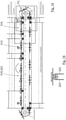
- FIG. 1A and 1B shows a highly schematized representation of a packaging device according to the invention with a forming unit according to the invention in a side view and top view.
- the Figure 1B an alternative embodiment variant of the packaging device according to FIG Figure 1A , which is why the same features are given the same reference numbers, but are preceded by the number "1".
- a band-shaped film F is unwound from a film coil Fc.
- an aluminum foil an aluminum foil that is laminated with a sealing layer, for example, malleable paper that is optionally also laminated with a sealing layer, or plastic film can be used as the foil material.
- the film does not have to be flexible at room temperature, but can also only have the flexibility shown in higher temperature ranges.
- the film can already be thermally acted on by heating elements or the like in the unwinding area A or in an adjoining area B in the conveying direction RF, referred to here as the calming area B.
- plastic plates or the like to convey material instead of a foil coil. These can likewise be thermally heated in the first region A or in the region B adjoining it in the conveying direction R F and thereby made deformable.
- the foil coil is pushed onto a mandrel.
- this is mounted on one side so that a quick change can take place when the film ends.
- the film coil is against pushed a stop.
- the roll can be fixed with a second clamping ring.
- After unrolling a film loop (in the unrolling area A of the 1 shown) the film F is fed into the packaging device 10. This is necessary to keep the film free of tension, otherwise it could tear.
- the loop size or the sagging of the film F in the unwinding area A can be determined, for example, using a sensor.
- the film F should calm down when running in a straight line. For this purpose, it is guided laterally over a predetermined length, so that slight inclinations can be corrected when the film is fed in.
- a print mark sensor can be provided at the end of the calming area B, which detects the position of the film passing through. Depending on the position, the film can then be accelerated or decelerated. In the embodiment shown, this is done with the help of two foil rollers (in the calming area B of the 1 shown schematically on the left), between which the film F runs. The conveying speed of the film F in the area of these film rollers can be passed on to a downstream conveying unit 18 of the packaging device 10 as a reference speed.
- the film can also be braked or accelerated via fixing belts or belt belts 186, 188, which can run above the conveyor unit 18, for example (cf. also Figure 1B ).
- the film F is then conveyed through the packaging device 10 via the conveying unit 18 .
- the film F runs through the following units together with the conveyor unit 18: forming unit 12, unit for fitting and folding over 14, and closing unit 16.
- the conveyor unit 18 comprises a number of film carriers 20, which are continuously conveyed through the packaging device 10 via a circulating conveyor system, for example a conveyor belt, a conveyor chain or a rotating conveyor plate, which is not covered by the invention in an embodiment.
- a conveyor chain 22 is provided, to which the film carriers 20 are attached.
- two adjacent film carriers 20 can be connected to one another in pairs via a folding joint 20a.
- the film carrier 20, which is running in front for example, to be firmly connected to the circulating conveyor system, i.e., for example, the conveyor chain 22, while the film carrier 20 that is trailing in each case, which can be folded over onto the film carrier 20 running in front via the folding joint 20a (indicated by the two folding arrows K), can be detachably attached to this.
- the film carrier 20 that is trailing in each case which can be folded over onto the film carrier 20 running in front via the folding joint 20a (indicated by the two folding arrows K)
- the individual film carriers have, for example, suction bores through which the film can be sucked.
- the vacuum can be generated by a vacuum fan or the like mounted under the film carrier (not shown).
- the film pieces can be embossed in the forming unit 12 by cutting and/or shaping into the film carrier 20, ie connected to it in a form-fitting manner. This solution is described below with reference to the Figures 2A to 2C referred to more closely.
- the guides may comprise thin sheets or belts 186, 188 fixedly mounted to the machine frame.
- the belts 186, 188 run at the same speed as the film carriers 20.
- the film runs under these guides and above the film carrier.
- the guide is recessed accordingly in the respective processing units, so that they cannot collide with the processing tools.
- the film F runs between the respective belts 186, 188 and the conveyor unit 118 and is pressed by the belts against the film carrier 120 in such a way that it cannot slip or fly away during transport.
- a separate guide is no longer absolutely necessary.
- the formed package is held securely to the film carrier by gravity (due to the product being picked up).
- the essentially planar foil F is segmented, ie a piece of foil is cut off from the foil web. This is achieved with the aid of a segment cutting blade 34 which is able to move relative to the foil carrier 20 in a lifting movement Z.
- the cut piece of foil or foil semi-finished product FH rests on the continuously moving foil carrier 20 and moves into the processing area of the forming tool, which is composed of a forming punch 30 and a corresponding die 32 .
- a hold-down device can also be provided (not shown here), which clamps the film F between itself and the bearing surface of the film carrier 20 .
- the forming process is carried out before the film is segmented.
- the segment blade 34a upstream of the forming die 30 in the conveying direction RF is not used for this purpose, but rather a cutting blade 34b downstream of it.
- the preformed film whether segmented or not, can also be end-cut, ie the preformed semi-finished film FH with the desired end contour is cut out of the film with the aid of a end cutting blade 36 shown schematically.
- the step of final cutting takes place in the area of the closing unit 16, ie after the loading and folding of the semi-finished molds.
- the end cutting step is carried out in the area of the forming unit 12, the end cutting can be carried out in the same stroke, i. H. be carried out with the same stroke movement Z, in which the shaping was carried out.
- a drive that in the exemplary representation of 1 is provided with the reference number 24 and allows movement in the X direction.
- the drive 24 is connected via force application points 26 and 28 to the carriage of the respective machining tools.
- processing tools can also be reset by means of an elastic reset unit (not shown).
- the unit for loading and folding 14 is in the illustrated embodiment 1 only indicated.
- the preformed semi-finished film FH can be manually or automatically loaded with food products or products of all kinds in this area 14, ie every second semi-finished film FH is loaded in the illustrated embodiment.
- the unequipped semi-finished film products are then folded over onto the equipped semi-finished film products by means of the foldable film carrier 20, with the product itself being used to center the folded semi-finished film product FH and the now emptied film carriers can then be folded back onto the conveyor system in a further folding step will.
- the two semi-finished foils FH are brought together and form a common housing for the product contained therein (cf. e.g. also Figure 7A ).
- the closing unit 16 the two semi-finished film products are connected to one another.
- a combination of these two methods is also conceivable.
- the mechanical closure reference is made, inter alia, to a method according to the publication AT 221906B referred.
- a thermal process reference is made, for example, to publication DE 1 211 913 B referred.
- a combined method is, for example, from the publication U.S. 2012/0204412 A1 known in connection with the joining of metal components in automobile construction.
- a closing mold 38 is shown by way of example as the upper tool part with a counter-holder 40 as the lower tool part.
- the packaged products can finally be removed in a removal area E following the conveying direction R F .
- a removal area E following the conveying direction R F .
- different solutions are conceivable, for example, they can fall onto a chute or the like as the film carrier rotates. Alternatively, they can of course also be removed manually or automatically.
- FIGS. 2A and 2C show two variants of a tool system according to the invention for crimping or caulking and thus fixing a semi-finished film F H on a film carrier 20. Accordingly, the same features are provided with the same reference symbols, but in the second embodiment these are preceded by the number "1".
- FIG. 2A and 2B shows a three-part tool system 42 according to the invention with an upper tool part 64, a lower tool part 70 and a foil carrier 20, the foil carrier 20 forming the middle part of the tool.
- the bearing surface of the film carrier 20 is formed by a functional ring 48, which can be covered with different functional sections.
- One of these functional sections can be seen in the inclined recess 48a, into which a forming die 46 of the tool upper part 64 can dip.
- a circumferential foil flange F F rests at least partially in the area of the recess 48 .
- the forming stamp 46 is now inserted into the recess 48a with its forming tip 44, the partially resting foil flange FF is inserted into the recess 48a by this, which leads to caulking of the foil flange FF . Because the recess 48a is at an angle ⁇ (cf. Figure 2B ) is inclined to the film support plane and that this deformation of the film flange F F is carried out on two opposite sides of the circumferential flange F F , a secure form-fitting fixation of the semi-finished film FH on the film carrier 20 is achieved.
- ⁇ cf. Figure 2B
- Figure 2C differs from only that Figure 2A that the lower tool part 170 is accommodated in a different way in the middle part of the tool, ie the film carrier 120 .
- This is intended to show in particular that this specific solution for crimping or Caulking of the semi-finished film on the film carrier for better fixation can be seen separately from the specific configuration of the film carrier and the tool center part 170 .
- This aspect of the invention is of course also conceivable detached from the remaining aspects of the invention, in particular from the design of the tool system, the arrangement for molding with a hold-down device and the specific molding process, and can accordingly also be used in differently designed devices or in connection with a single-stage molding process come into use.
- Figure 1 shows the forming unit 12 of the packaging device 10 according to the invention in more detail.
- This is also designed as a three-part tool system with an upper tool part in the form of the forming punch 30 , with a lower tool part in the form of the die 32 and a central tool part in the form of a film carrier 20 .
- a film F lies on the film carrier 20 and is to be shaped with the aid of the forming punch 30 and the associated die 32 .
- the film carrier 20 has a central through-opening 50 which forms a receiving area for the lower tool part, ie the matrix 32 .
- orientation recordings 52 are also provided, in which corresponding projections 54 on the die 32 are received and can be secured against twisting of the die relative to the film carrier.
- the presentation of the film carrier 20 was omitted to simplify the presentation.
- the die 32 has a mold recess 56 on its shaping upper side, the inner contour of which is essentially adapted to a shaping outer contour 32 of the stamp 30 .
- it has a holder receptacle 58 on its non-forming underside for connection to a lifting movement Z (cf. 1 ) provided introductory holder.
- the presentation of the film carrier 20 was omitted to simplify the presentation.
- the die 32 has a mold recess 56 on its shaping upper side, the inner contour of which is essentially adapted to a shaping outer contour 62 .
- a holder mount 58 for connection to a lifting movement Z (cf. 1 ) provided introductory holder.
- a first step (cf. Figure 10A ) the punch 30 and the die 32 are moved towards one another to form the film, i.e. the punch 30 is in particular moved into the die 32 to a certain extent, with the minimum distance between the outer punch contour 62 and the inner die contour 56 being greater when they are moved towards one another than the thickness of the foil to be deformed.
- the film has already been preformed into a semi-finished film FH, with a film flange FF radially surrounding the preformed area of the semi-finished film FH within the die 32 resting on the underside of a hold-down device 90 .
- the hold-down device 90 has a minimum distance from the bearing surface 92 of the shaping unit 12 in the first molding step, so that the film flange FF is not clamped between the bearing surface 92 and the contact surface of the hold-down device 90.
- this results in reduced friction and thus reduced stress on the film, which means that the risk of the film tearing can be reduced even when using a comparatively thin film.
- a further molding step in the illustration shown a final second molding step
- the hold-down device 90 and the punch 30 brought into the usual molding position in which the distance from the respective contact or molding partners, i. H. the contact surface 92 or the mold recess 56, is less than the minimum distance in the first molding step, for example essentially corresponds to the film thickness of the film to be shaped.
- the hold-down device 90 is held displaceably by means of an elastic spring system 94 and can be held at the desired distance from the bearing surface 92, for example by means of spacers (spacers, spacer projections or the like) which are not shown.
- one and the same pair of punches and dies is used for the two-stage molding process.
- the die 32 or 132 has an elastic insert 60 or 160, which is intended to serve for improved reshaping of, in particular, those mold areas (critical area CA) that have strong contour transitions.
- FIG. 7A to 7C a further exemplary embodiment of a tool system according to the invention of the packaging device is shown.
- This relates to the final cutting of the semi-finished film F H using a cutting knife 66 with a circumferential cutting contour.
- the cutting knife 66 is attached to the tool upper part 64 and is moved with a lifting movement in direction Z onto the tool middle part in the form of the foil carrier 20 .
- the film carrier 20 has an additional functional ring 48 which rests on the film carrier 20 and forms the bearing surface for the film semi-finished products or their peripheral film flanges F F .
- a circumferential cutting groove 82 is provided on the functional ring 48 as a functional section, into which the cutting blade 66 can dip. In principle, it is also conceivable to form the cutting groove 82 directly on the foil carrier 20 .
- a hold-down device 68 is also shown, which is able to clamp the film flanges F F lying against one another of the semi-finished film products FH lying on top of one another against the functional ring 48 .
- the hold-down device 68 is resiliently mounted in a known manner on the tool upper part 64 in such a way that it comes into clamping contact, preferably against the foil flanges F F , before the cutting blade 66 is able to enter the cutting groove 82 .
- Figure 7C differs from that of the only in this respect Figure 7A that the lower tool part 170 is received directly on the foil carrier 120 . Accordingly, the features in the Figures 7A and 7C given the same reference signs, but these in Figure 7C preceded by the digit "1". The one related to the Figures 7A to 7C The aspect described is of course also conceivable in connection with such tool systems which are not designed in three parts and in which, in particular, the film carrier does not form part of the tool system.
- the final cutting step can take place before the mechanical and/or thermal connection of the semi-finished foils FH or afterwards.
- the end cutting can be done before the connection, while with a thermal connection, for example by sealing, the end cutting can be done both before and after the connection.
- the sealing is carried out before the folding or flanging.
- a sealing layer is only applied on one side.
- Figures 8A to 8D show an example of how a floating mounting of at least one of the tool parts of a tool system according to the invention can be designed, which enables better alignment of the tool parts during a machining step. So is in Figure 8A a tool system with an upper tool part 64 and a lower tool part 70 is shown as an example. To simplify the illustration, the middle part of the tool is not shown here.
- the tool upper part 64 is connected via an adapter plate 72 to a push rod 84 that initiates the machining movement.
- the push rod 84 and the adapter plate 72 are firmly connected to one another, for example formed in one piece, welded or joined together in some other way.
- the tool upper part 64 is attached to the adapter plate 72 by means of four bolts 74 .
- a clearance of 0.5 mm, for example, is provided between the respective bolts 74 and the associated receptacle of the adapter plate 72, which enables a corresponding tolerance compensation in the event of positioning errors between the upper tool part 64 and the lower tool part 70. This is particularly evident in the detailed representation of the Figure 8D refer to.
- the floating bearing enables tolerance compensation. in several directions transverse to the machining movement, in this case in a plane perpendicular to the machining direction.
- both the upper tool part and the lower tool part can be provided with a corresponding floating bearing.
- bevels allow the individual tool parts to be brought together and positioned relative to one another more easily.
- Other measures such as guide projections, which are able to dip into corresponding recesses on a different one of the tool parts in each case, in order to ensure secure positioning during the machining process, are of course also conceivable.
- FIGS. 9A to 9C finally show a further exemplary embodiment of a three-part tool system of the packaging device according to the invention.
- this involves a positioning device 76, by means of which a protruding edge of the already joined packaging in the form of the semi-finished film F H is positioned at a predetermined angle can to simplify the handling of the joined packaging.
- a circumferential forming area 80 or 180 is provided on the lower tool part 70 or the film carrier 20 or an associated functional ring 48, into which a corresponding forming die 78 or 178 can immerse in order to place the protruding edge of the semi-finished film FH accordingly.
- an angle of inclination of ⁇ is provided on the forming stamp 78 and the corresponding forming area 80 .
- FIGS 9A and 9C show two variants for a tool system according to the invention for creating. Accordingly, the same features are given the same reference numerals, but in the second embodiment these are preceded by the numeral "1".
- Figure 9C differs from only that Figure 9A that the lower tool part 170 is accommodated in a different way in the middle part of the tool, ie the film carrier 120 .
- This is intended to show in particular that this specific solution for applying the film edge is to be viewed independently of the specific design of the packaging device, the tool system and in particular the film carrier 120 and the tool center part 170 .
- the application device 76 for applying the protruding edge can be designed in such a way that the protruding edge is not applied completely, but that a portion of the edge remains.
- the contact contour of the packaging would not be circular, but rather open at the point where the edge should not be placed.
- the contact edge or the contact form is interrupted and the edge or the tear-off aid protrudes outwards. This results in a user-friendly tear-off aid that protrudes from the packaged product in such a way that a user can easily grasp it.
- the feed device 76 can also be arranged outside the machine, from where it can be brought to the desired location by means of suitable devices, in particular handling devices such as multi-axis robots, linear feed devices or the like.
- the application device 76 can also be designed in such a way that it adjusts to different contours of the packaging or can be adjusted to different contours of the packaging. This can be achieved, for example, by means of suitable resilient or flexible elements that can adapt to different contours.
- FIG. 11 shows in a very schematic way an alternative embodiment of the tooling system of the packaging device.
- the features are off Figure 1A corresponding features are provided with the same reference numerals, but preceded by the number "2".
- the conveyor unit 218 according to 11 designed at least in sections thereof as a discontinuously operating conveyor unit 218.
- the conveying unit 218 is discontinuous in the area of the molding unit 212, ie it operates discontinuously in the area of the molding unit 212 or is operated discontinuously in the area of the molding unit 212. This simplifies the processing of the semi-finished film F H using the tool system and reduces wear and tear on the tool system.
- the conveyor unit 218 has a linear drive device 223, indicated very schematically, for the individual tool center parts, which can be designed and operated in a manner known per se.
- the linear drive device 223 makes it possible to achieve very high speeds when transporting the semi-finished film products F H .
- each tool center part can be controlled separately, so that it is very easy to stop the tool center parts in the area of the forming unit 212, so that the forming of the semi-finished film FH can be carried out more easily than in a completely continuous operation.
- the tool centers can be continuous and possibly at higher speeds and/or accelerations than in the referenced figures Figures 1A and 1B described embodiments are moved, so that there are no delays in the processing of the film F.
- these can of course be synchronized with one another, for example by means of a control device, not shown, in order to ensure trouble-free operation.
- the linear drive device 223 other drives can also be used which enable discontinuous operation of the conveyor unit 218 at least in sections.
- the at least partial use of pneumatic or hydraulic cylinders is also possible.
- the central drive 24 provided in the continuously operating conveyor unit 18 or 118 would be omitted or replaced by the linear drive device 223 .
- FIG. 12A and 12B an alternative embodiment of a securing arrangement 300 for fixing the semi-finished film F H is shown.
- the securing arrangement 300 has a clamping element 301 and at least one spring element 302 which presses the clamping element 301 in the direction of the film carrier 20 , 120 .
- respective clamping elements 301 are provided on two opposite sides of the tool center part, which are pressed in the direction of the film carrier 20, 120 with two spring elements 302 each.
- the spring elements 302 are leg springs, which are supported with one leg on the tool center part and with the other leg on the clamping element 301 .
- the securing arrangement 300 can have a link guide or the like, not shown, which is in operative connection with the at least one clamping element 301 or preferably with both clamping elements 301 in such a way that by means of the link guide an opening of the respective Clamping element 301 can be effected against the force of the spring element 302. A targeted opening of the security arrangement 300 is thereby achieved.
- the link guide can be connected to the clamping elements 301 via a plunger (not shown), which acts on the clamping elements 301 and opens them against the force of the spring elements 302 .
- clamping elements 301 In a way that is not shown, however, it is also conceivable for the clamping elements 301 to be opened or released against the force of the spring elements 302 by means of servomotors or other suitable devices.
- a further possibility for securing the semi-finished film F H can be that the semi-finished film F H of the film packaging is secured during transport on the film carrier 20, 120 by folding the film edges onto the film carrier 20, 120.
- the film edges are placed against the film carrier 20, 120, for example at an angle of 90°, so that they cannot slip on the film carrier 20, 120 during transport.
- the semi-finished film FH is not pierced, but only folded over at its edges. A combination of crimping and turning over the edges is also possible.
- the at least one punch 230 and the at least one die 232 are moved relative to one another to form the film F, with both the punch 230 being moved in the direction of the die 232 and the die 232 being moved in the direction of the punch 230.
- the punch 230 and the die 232 are moved toward each other.
- the stamp 230 and the die 232 can be moved completely independently of one another, for which purpose suitable drives can be used.
- the film carrier 220 remains stationary.
- the die 232 can be moved in the direction of the punch 230 in such a way that the die 232 comes into contact with the film F before the punch 230 reaches a lower reversal point.
- the matrix 232 is in contact with the foil F, the latter begins to deform so that it is pre-formed by the contact with the matrix 232.
- the foil F is pressed upwards in this way, which leads to a further reduction in the required hold-down forces exerted by a hold-down device 290 .
- the matrix 232 can also be used to fix the position of the film F before it is deformed, which results in an improvement in the position and orientation of the printed image.
- the die 232 does not have to be contoured exactly like this be like in the Figures 13A, 13B and 13C shown and can also be used with smooth or smoother shapes than the shape shown.
- the stamp 230 can also be controlled in such a way that, after dipping into the film carrier 220, it is moved back again in order to support the described pre-shaping of the film F by the die 232. This also results in the possibility of realizing more complex shapes of the film packaging, since the film F can be shaped from two sides.
- the retraction of the punch 230 also allows the sheet material to move toward the die 232 to facilitate deformation by the die 232 as described.
- the described upward movement of the punch 230 can also be triggered or supported by the die 232 if the force acting on the die 232 is higher than the force acting on the punch 230 .
- FIG. 14 shows in a schematic way a further alternative embodiment of the tooling system of the packaging device. Again, the characteristics are off Figure 1A corresponding features are provided with the same reference numerals, but preceded by the number "3".
- the conveyor unit 318 according to 14 In contrast to the continuously operating conveyor unit 18 according to Figure 1A or the continuously operating conveyor unit 118 according to Figure 1B is the conveyor unit 318 according to 14 , similar to the conveying unit 218 according to FIG 11 , formed at least in sections thereof as a discontinuously operating conveyor unit 318.
- the conveyor unit 318 is similar to the conveyor unit 218 according to FIG 11 , is designed discontinuously in the area of the forming unit 312, ie it works discontinuously in the area of the forming unit 312 or is operated discontinuously in the area of the forming unit 312, which in turn simplifies the processing of the semi-finished foils FH using the tool system and reduces wear on the tool system.
- the conveyor unit 318 still has sections in which the discontinuously operated sections are synchronized with the continuously operated sections, ie in which a transition from the discontinuously operated sections to the continuously operated sections is realized.
- the continuously operated sections of the conveyor unit 318 are shown with solid lines, the sections in which the synchronization takes place with short dashed lines and the discontinuously or cyclically operated sections of the conveyor unit 318 with long dashed lines.
- the conveying unit 318 has several, in the present case designed as a belt 323, limp drive elements which are used to form the continuously operated sections, the discontinuously operated sections and the sections in which the Synchronization of the intermittently operated sections with the continuously operated sections takes place, can be used.
- the flexible drive elements could also be designed as a chain or in some other suitable way.
- the belts 323 are passed around respective pulleys, with positive engagement between the belts 323 and the pulleys being preferred.
- the belts 323 can thus be, for example, toothed belts, cam belts or the like.
- the flexible drive elements i.e. the belts 323 in the present case, enable a particularly simple transition between the continuously and discontinuously operated sections of the conveyor unit 318, which not only allows very high speeds to be achieved when transporting the semi-finished film products FH , but also safe operation of the conveyor unit 318 is guaranteed.
- the flexible drive elements can be controlled by respective servomotors in order to ensure that the process carried out with the conveyor unit 318 or the method carried out with the same is always under control.
- the flexible drive elements can be controlled in any desired manner by the servomotors, so that any desired synchronization between the movement sequences is possible, in particular the desired synchronization.
- asynchronous motors with corresponding electronic control can also be used.
- each tool center part can be controlled separately, so that the tool center parts can be stopped very easily in the area of the forming unit 312, as a result of which the forming of the semi-finished foils FH can be carried out more easily than in a completely continuous operation.
- the straps 323 can be provided with suitable elevations, depressions or the like on their sides facing the same.
- the tool centers can be continuously and possibly at higher speeds and/or accelerations than in the referenced figures Figures 1A and 1B described embodiments are moved, so that there are no delays in the processing of the film F.
- the central drive 24 provided for the continuously operating conveyor unit 18 or 118 could in turn be omitted.
- the tool system described can also be used in areas other than packaging.
Landscapes
- Engineering & Computer Science (AREA)
- Mechanical Engineering (AREA)
- Auxiliary Devices For And Details Of Packaging Control (AREA)
- Confectionery (AREA)
Claims (12)
- Système d'outil à utiliser dans un dispositif d'emballage (10 ; 110 ; 210 ; 310) pour emballer des produits alimentaires, en particulier des pièces creuses de chocolat, au moyen d'un emballage en feuille, le dispositif d'emballage présentant plusieurs unités de traitement pour le traitement de l'emballage en feuille, comprenant au moins trois parties d'outil, à savoir une partie d'outil centrale ainsi qu'une partie d'outil inférieure (70, 170) et une partie d'outil supérieure (64 ; 164) qui sont aptes à collaborer dans le fonctionnement, dans lequel la partie d'outil centrale sert à recevoir et à transporter au moins une feuille semi-finie (FH) à traiter de l'emballage en feuille entre différentes unités de traitement du dispositif d'emballage (10 ; 110 ; 210 ; 310), et la partie d'outil centrale est apte à collaborer avec au moins une autre partie d'outil (64, 164 ; 70, 170) du système d'outil, l'autre partie d'outil (64, 164 ; 70, 170) étant une partie d'outil (64, 164 ; 70, 170) d'une des unités de traitement qui servent à traiter la feuille semi-finie (FH) de la réception sur la partie d'outil centrale jusqu'à sa finition comme emballage en feuille, et la partie d'outil centrale présentant au moins une interface au moyen de laquelle elle est compatible avec au moins une partie d'outil (64, 164 ; 70, 170) de chacune de ces unités de traitement, la partie d'outil centrale étant entraînée au moyen d'une unité de transport (218, 318) et comprenant en particulier un support de feuille (20, 120) auquel est associée au moins une feuille semi-finie (FH), caractérisé en ce que l'unité de transport (218, 318) est configurée au moins par sections comme une unité de transport (218, 318) travaillant de façon continue, et est configurée au moins par sections comme une unité de transport (218, 318) travaillant de façon discontinue, en prévoyant des sections dans lesquelles a lieu une synchronisation des sections fonctionnant de façon discontinue avec les sections fonctionnant de façon continue.
- Système d'outil selon la revendication 1,
caractérisé en ce que l'unité de transport (218) présente un dispositif d'entraînement linéaire (223) pour la partie d'outil centrale. - Système d'outil selon la revendication 1 ou 2,
caractérisé en ce qu'au moins une partie d'outil (64, 164 ; 70, 170), en particulier la partie d'outil inférieure (70, 170) et/ou la partie d'outil supérieure (64, 164), est montée de façon flottante dans au moins une direction transversale à la direction de traitement (z). - Système d'outil selon la revendication 3,
caractérisé en ce qu'au moins une partie d'outil (64, 164 ; 70, 170), en particulier la partie d'outil inférieure (70, 170) et/ou la partie d'outil supérieure (64, 164), présente ou présentent des chanfreins d'assemblage pour faciliter un rassemblement des parties d'outil pendant une étape de travail. - Système d'outil selon une des revendications précédentes,
caractérisé en ce que la partie d'outil inférieure (70, 170) et/ou la partie d'outil supérieure (64, 164) d'une unité de traitement peuvent aller et venir au moins par sections le long de la direction de transport (RF) de la partie d'outil centrale. - Système d'outil selon une des revendications 1 à 5,
caractérisé en ce que l'au moins une interface de la partie d'outil centrale et du support de feuille (20, 120) comprend une zone de réception et qu'au moins une partie d'outil (64, 164 ; 70, 170) d'une des unités de traitement du dispositif d'emballage peut être reçue au coup par coup et par sections dans la zone de réception de la partie d'outil centrale et du support de feuille (20, 120), la zone de réception de la partie d'outil centrale et du support de feuille (20, 120) présentant en particulier un contour intérieur qui correspond avec le contour extérieur correspondant de la partie d'outil (64, 164 ; 70, 170) concernée de l'unité de traitement concernée. - Système d'outil selon la revendication 6,
caractérisé en ce que la partie d'outil centrale ou le support de feuille (20, 120) est configuré de façon approximativement plane avec un orifice de passage (50, 150) approximativement central faisant office de zone de réception, une zone de façonnage périphérique (80, 180) avec un chanfrein d'environ 45 degrés qui découche par exemple dans l'orifice de passage (50, 150) pouvant être prévue en particulier dans la zone de l'orifice de passage central. - Système d'outil selon une des revendications 1 à 5,
caractérisé en ce que l'au moins une interface de la partie d'outil centrale et du support de feuille présente une rainure de coupure périphérique (82, 182) et/ou au moins deux réceptacles de tension (48a, 148a). - Système d'outil selon une des revendications 1 à 5,
caractérisé en ce que l'interface de la partie d'outil centrale et du support de feuille présente une bague fonctionnelle (48, 148) formée séparément qui présente en particulier la zone de façonnage périphérique (80, 180) et/ou la rainure de coupure périphérique (82, 182) et/ou les réceptacles de tension (48a, 148a). - Dispositif d'emballage (10 ; 110 ; 210 ; 310) pour emballer des produits alimentaires, en particulier des pièces creuses de chocolat, au moyen d'un emballage en feuille qui comprend au moins deux pièces façonnées en feuille, lequel dispositif d'emballage présente plusieurs unités de traitement pour le traitement des feuilles semi-finies (FH) de l'emballage en feuille, à savoir :une unité de coupe pour découper les feuilles semi-finies (FH),une unité de façonnage (12, 112) pour façonner les feuilles semi-finies (FH) etune unité de fermeture (16, 116) pour combiner les feuilles semi-finies en un boîtier fermé pour le produit alimentaire reçu, ainsiqu'une unité de transport (218, 318) pour transporter les feuilles semi-finies (FH) de l'emballage en feuille entre les différentes unités de traitement du dispositif d'emballage (10, 110),caractérisé en ce que l'unité de transport (218, 318) est configurée par sections comme une unité de transport (218, 318) travaillant de façon continue et par sections comme une unité de transport (218, 318) travaillant de façon discontinue, en prévoyant des sections dans lesquelles a lieu une synchronisation des sections fonctionnant de façon discontinue avec les sections fonctionnant de façon continue.
- Dispositif d'emballage (10 ; 110 ; 210 ; 310) selon la revendication 10, caractérisé en ce que l'unité de transport (218, 318) présente des éléments d'entraînement souples pour former les sections fonctionnant de façon continue, les sections fonctionnant de façon discontinue et les sections dans lesquelles la synchronisation des sections fonctionnant de façon discontinue avec les sections fonctionnant de façon continue a lieu.
- Dispositif d'emballage (10 ; 110 ; 210 ; 310) selon la revendication 11, caractérisé en ce que les éléments d'entraînement souples peuvent être commandés au moyen de moteurs électriques commandés électroniquement.
Applications Claiming Priority (5)
| Application Number | Priority Date | Filing Date | Title |
|---|---|---|---|
| DE102017129958 | 2017-12-14 | ||
| DE102017129968 | 2017-12-14 | ||
| DE102018111041.3A DE102018111041A1 (de) | 2017-12-14 | 2018-05-08 | Verfahren und Formeinheit zum Formen von Folienformteilen |
| DE102018111054.5A DE102018111054A1 (de) | 2017-12-14 | 2018-05-08 | Werkzeugsystem für eine Verpackungsvorrichtung |
| PCT/EP2018/084953 WO2019115766A2 (fr) | 2017-12-14 | 2018-12-14 | Système d'outil pour un dispositif d'emballage ainsi que procédé et unité de façonnage pour le façonnage de pièces façonnées en feuille |
Publications (2)
| Publication Number | Publication Date |
|---|---|
| EP3724083A2 EP3724083A2 (fr) | 2020-10-21 |
| EP3724083B1 true EP3724083B1 (fr) | 2022-02-23 |
Family
ID=66820022
Family Applications (1)
| Application Number | Title | Priority Date | Filing Date |
|---|---|---|---|
| EP18827011.0A Active EP3724083B1 (fr) | 2017-12-14 | 2018-12-14 | Système d'outil pour un dispositif d'emballage ainsi que unité de façonnage pour le façonnage de pièces façonnées en feuille |
Country Status (4)
| Country | Link |
|---|---|
| US (1) | US20210002012A1 (fr) |
| EP (1) | EP3724083B1 (fr) |
| PL (1) | PL3724083T3 (fr) |
| WO (1) | WO2019115766A2 (fr) |
Families Citing this family (1)
| Publication number | Priority date | Publication date | Assignee | Title |
|---|---|---|---|---|
| DE102021130302A1 (de) | 2021-11-19 | 2023-05-25 | Stampac Gmbh | Verfahren und Vorrichtung zum Verpacken eines Gegenstands |
Citations (5)
| Publication number | Priority date | Publication date | Assignee | Title |
|---|---|---|---|---|
| CH408756A (de) | 1961-12-27 | 1966-02-28 | Kleindienst Gerhart | Vorrichtung zum Umhüllen von unregelmässig gestalteten Gegenständen, insbesondere von Hohlkörpern aus Schokolade |
| DE4001993A1 (de) | 1989-01-24 | 1990-07-26 | Manfred Wanzke | Presse mit praezise gefuehrtem werkzeug |
| DE102007030008A1 (de) | 2007-06-28 | 2009-01-02 | Bikoma Ag Spezialmaschinen | Formstation zum Herstellen von Formkörpern |
| EP2366631A1 (fr) | 2010-03-16 | 2011-09-21 | Soremartec S.A. | Dispositif, appareil et procédé pour conditionner un article dans un boîtier de matériaux en feuille |
| WO2015189564A1 (fr) | 2014-06-09 | 2015-12-17 | C Pack Packaging Machinery Limited | Système d'emballage |
Family Cites Families (29)
| Publication number | Priority date | Publication date | Assignee | Title |
|---|---|---|---|---|
| NL279067A (fr) | ||||
| GB728903A (en) * | 1951-10-20 | 1955-04-27 | Rose Brothers Ltd | Improvements in the packaging of plastic substances |
| US2896387A (en) * | 1956-10-02 | 1959-07-28 | Brock Herbert William | Machine for packaging articles |
| AT221906B (de) | 1960-02-04 | 1962-06-25 | Malba Ges Mit Beschraenkter Ha | Verfahren und Vorrichtung zur Herstellung von Gieß- und Hüllformen aus Metallfolien für Figuren aus Süßwaren |
| DE1211913B (de) | 1963-11-06 | 1966-03-03 | Kaupert Guenter Dr Ing | Vorrichtung zum festen Verbinden von Folienformhalbschalen fuer Schokoladenfiguren u. dgl. |
| DE1959573A1 (de) | 1969-11-27 | 1971-06-03 | Rovema Gmbh | Ziehpresse |
| US3750362A (en) * | 1972-03-29 | 1973-08-07 | Standard Packaging Corp | Method of packaging granular material |
| US3964237A (en) * | 1972-05-10 | 1976-06-22 | Portion Packaging Limited | Apparatus for the production of a product filled container |
| DE2420680A1 (de) | 1974-04-29 | 1975-11-13 | Kaupert Guenter Dr Ing | Verfahren zum herstellen von becherartigen behaeltern aus duennem metallband, insbesondere aus aluminium-folie, vorrichtung zur durchfuehrung dieses verfahrens sowie danach hergestellte behaelter |
| DE3243500C2 (de) * | 1982-11-24 | 1984-09-13 | Ferrero Ohg, 3570 Stadtallendorf | Verfahren und Vorrichtung zum Verpacken eines räumlichen Gegenstandes |
| US5371999A (en) * | 1991-11-12 | 1994-12-13 | Inter Pak Equipment Corporation | Shrink film wrapping machine |
| CH691445A5 (de) | 1996-04-24 | 2001-07-31 | Alusuisse Tech & Man Ag | Verfahren zum Herstellen von Formpackungen. |
| DE19725949C2 (de) * | 1997-06-19 | 1999-09-02 | Silver Plastics Gmbh & Co Kg | Verpackungsschale für Lebensmittel und ein Verfahren zum Herstellen dieser Verpackungsschalen |
| US5934049A (en) * | 1998-01-27 | 1999-08-10 | Cerf; Alain | Automated film wrapping apparatus |
| ITMO20010219A1 (it) * | 2001-11-15 | 2003-05-15 | Elopak Systems | Apparati e metodo |
| DE10229377A1 (de) * | 2002-06-26 | 2004-01-15 | Bos Berlin Oberspree Sondermaschinenbau Gmbh | Formvorrichtung zur Herstellung eines Komponententrägerbandes |
| ITMO20080085A1 (it) * | 2008-03-25 | 2009-09-26 | Sarong Spa | Apparato per formare contenitori asettici |
| ES2373413T3 (es) * | 2008-04-18 | 2012-02-03 | Theegarten-Pactec Gmbh & Co. Kg | Sistema de aportación de productos y correspondiente procedimiento. |
| DE102008034996B4 (de) | 2008-07-25 | 2010-11-18 | Benteler Automobiltechnik Gmbh | Vorrichtung zum Warmformen, Presshärten und Schneiden eines Halbzeugs aus härtbarem Stahl |
| IT1401804B1 (it) * | 2010-06-30 | 2013-08-28 | Azionaria Costruzioni Acma Spa | Macchina di incarto per prodotti. |
| BE1019661A3 (nl) * | 2010-12-01 | 2012-09-04 | Vanhee Engineering B V B A | Voorgevormde verpakkingseenheid voor een voedingsproduct, en een werkwijze en een inrichting voor het vervaardigen ervan. |
| US8640320B2 (en) | 2011-02-10 | 2014-02-04 | GM Global Technology Operations LLC | Method of joining by roller hemming and solid state welding and system for same |
| ITTO20130097A1 (it) | 2013-02-06 | 2014-08-07 | Soremartec Sa | Procedimento per realizzare una confezione di un prodotto alimentare, in particolare un prodotto dolciario |
| US9707156B2 (en) * | 2013-05-16 | 2017-07-18 | Sandy Wengreen | Storage systems and methods for medicines |
| DE102015101417B4 (de) | 2015-01-30 | 2016-09-01 | Chocal Aluminiumverpackungen Gmbh | Verfahren zum Herstellen einer Verpackung |
| US10625892B2 (en) * | 2015-10-14 | 2020-04-21 | Alkar-Rapidpak, Inc. | Web packaging machines with variable depth forming |
| DE102015220738A1 (de) | 2015-10-23 | 2017-04-27 | Chocal Aluminiumverpackungen Gmbh | Vorrichtung und Verfahren zum Abtrennen und Bereitstellen einer Folienteilstückeinheit von einem Lebensmittelverpackungsfolienband |
| US20170137159A1 (en) * | 2015-11-13 | 2017-05-18 | Mystic Pharmaceuticals, Inc. | Deep Draw Container Forming Method and Nutritional Product Containers |
| DE102016202814A1 (de) | 2016-02-24 | 2017-08-24 | Chocal Aluminiumverpackungen Gmbh | Verfahren und Maschine zum Verpacken eines Lebensmittelprodukts |
-
2018
- 2018-12-14 PL PL18827011.0T patent/PL3724083T3/pl unknown
- 2018-12-14 EP EP18827011.0A patent/EP3724083B1/fr active Active
- 2018-12-14 WO PCT/EP2018/084953 patent/WO2019115766A2/fr unknown
- 2018-12-14 US US16/772,483 patent/US20210002012A1/en not_active Abandoned
Patent Citations (5)
| Publication number | Priority date | Publication date | Assignee | Title |
|---|---|---|---|---|
| CH408756A (de) | 1961-12-27 | 1966-02-28 | Kleindienst Gerhart | Vorrichtung zum Umhüllen von unregelmässig gestalteten Gegenständen, insbesondere von Hohlkörpern aus Schokolade |
| DE4001993A1 (de) | 1989-01-24 | 1990-07-26 | Manfred Wanzke | Presse mit praezise gefuehrtem werkzeug |
| DE102007030008A1 (de) | 2007-06-28 | 2009-01-02 | Bikoma Ag Spezialmaschinen | Formstation zum Herstellen von Formkörpern |
| EP2366631A1 (fr) | 2010-03-16 | 2011-09-21 | Soremartec S.A. | Dispositif, appareil et procédé pour conditionner un article dans un boîtier de matériaux en feuille |
| WO2015189564A1 (fr) | 2014-06-09 | 2015-12-17 | C Pack Packaging Machinery Limited | Système d'emballage |
Also Published As
| Publication number | Publication date |
|---|---|
| US20210002012A1 (en) | 2021-01-07 |
| WO2019115766A2 (fr) | 2019-06-20 |
| WO2019115766A3 (fr) | 2019-08-08 |
| EP3724083A2 (fr) | 2020-10-21 |
| PL3724083T3 (pl) | 2022-10-17 |
Similar Documents
| Publication | Publication Date | Title |
|---|---|---|
| DE2327286C2 (de) | Verpackungsvorrichtung | |
| EP1604803B1 (fr) | Appareil pour fabriquer une bande de récipients étiquettés à partir d'un film thermoplastique chauffé | |
| DE2034154C2 (de) | Einrichtung zum Herstellen von oben offenen Behältern mit Verbundwänden | |
| DE102010034021B4 (de) | Tiefziehverpackungsmaschine und Verfahren mit einer Arbeitsstation zum Eindrücken von Vertiefungen in einen Deckel einer Verpackung | |
| DE4441097A1 (de) | Vorrichtung zum Herstellen und Anbringen eines Schutzbezuges bei einer Öffnung einer Wand für einen Behälter | |
| EP3626635A2 (fr) | Installation d'emballage et procédé de fabrication d'un emballage | |
| EP0963284A1 (fr) | Procede et dispositif de fabrication de recipients d'emballage en plastique, machine a emballer et recipient d'emballage | |
| EP3617076A1 (fr) | Machine d'emballage pourvue de plaque d'aspiration | |
| WO2004101192A1 (fr) | Dispositif d'usinage et utilisation dudit dispositif pour la fabrication de couvercles avec opercule a dechirer | |
| WO2014082991A1 (fr) | Machine d'emballage comprenant un système de changement d'outil | |
| WO2017001114A1 (fr) | Procédé de liaison d'un élément structurel à une barquette alimentaire | |
| EP3121123B1 (fr) | Machine d'emballage par emboutissage | |
| EP3724083B1 (fr) | Système d'outil pour un dispositif d'emballage ainsi que unité de façonnage pour le façonnage de pièces façonnées en feuille | |
| EP2883684A1 (fr) | Procédé et machine d'emballage dotée d'un porte-objet mobile | |
| EP3390234B1 (fr) | Moule présentant une coque en plusieurs parties | |
| EP0547449A2 (fr) | Emballage en carton ainsi que procédé et dispositif pour fabriquer celui-ci | |
| WO2017125282A9 (fr) | Outil de scellage pour un emballage pelliplaqué | |
| DE3023808C2 (de) | Verfahren und Vorrichtung zur Herstellung eines luftdicht verschlossenen Behälters | |
| DE2517534B2 (de) | Formvorrichtung zum herstellen von etikettierten behaeltern | |
| DE102018111054A1 (de) | Werkzeugsystem für eine Verpackungsvorrichtung | |
| DE69525537T2 (de) | Warmformvorrichtung zum warmformen von bandförmigen oder folienförmigen materialien | |
| EP3651980A1 (fr) | Procédé de fabrication d'emballages et emballeuse-emboutisseuse | |
| DE102013101055B4 (de) | Verfahren und Vorrichtung zum Tiefziehen | |
| EP2729375B1 (fr) | Machine d'emballage dotée d'un moyen de fixation d'une garniture intérieure sur un élément structurel | |
| DE102007011292B4 (de) | Formwerkzeug zum Aufbringen eines Etiketts auf ein tiefgezogenes Formteil und Verfahren zum Betreiben des Formwerkzeugs |
Legal Events
| Date | Code | Title | Description |
|---|---|---|---|
| STAA | Information on the status of an ep patent application or granted ep patent |
Free format text: STATUS: UNKNOWN |
|
| STAA | Information on the status of an ep patent application or granted ep patent |
Free format text: STATUS: THE INTERNATIONAL PUBLICATION HAS BEEN MADE |
|
| PUAI | Public reference made under article 153(3) epc to a published international application that has entered the european phase |
Free format text: ORIGINAL CODE: 0009012 |
|
| STAA | Information on the status of an ep patent application or granted ep patent |
Free format text: STATUS: REQUEST FOR EXAMINATION WAS MADE |
|
| 17P | Request for examination filed |
Effective date: 20200710 |
|
| AK | Designated contracting states |
Kind code of ref document: A2 Designated state(s): AL AT BE BG CH CY CZ DE DK EE ES FI FR GB GR HR HU IE IS IT LI LT LU LV MC MK MT NL NO PL PT RO RS SE SI SK SM TR |
|
| AX | Request for extension of the european patent |
Extension state: BA ME |
|
| STAA | Information on the status of an ep patent application or granted ep patent |
Free format text: STATUS: EXAMINATION IS IN PROGRESS |
|
| 17Q | First examination report despatched |
Effective date: 20210217 |
|
| DAV | Request for validation of the european patent (deleted) | ||
| DAX | Request for extension of the european patent (deleted) | ||
| GRAP | Despatch of communication of intention to grant a patent |
Free format text: ORIGINAL CODE: EPIDOSNIGR1 |
|
| STAA | Information on the status of an ep patent application or granted ep patent |
Free format text: STATUS: GRANT OF PATENT IS INTENDED |
|
| INTG | Intention to grant announced |
Effective date: 20211022 |
|
| GRAS | Grant fee paid |
Free format text: ORIGINAL CODE: EPIDOSNIGR3 |
|
| GRAA | (expected) grant |
Free format text: ORIGINAL CODE: 0009210 |
|
| STAA | Information on the status of an ep patent application or granted ep patent |
Free format text: STATUS: THE PATENT HAS BEEN GRANTED |
|
| AK | Designated contracting states |
Kind code of ref document: B1 Designated state(s): AL AT BE BG CH CY CZ DE DK EE ES FI FR GB GR HR HU IE IS IT LI LT LU LV MC MK MT NL NO PL PT RO RS SE SI SK SM TR |
|
| REG | Reference to a national code |
Ref country code: GB Ref legal event code: FG4D Free format text: NOT ENGLISH |
|
| REG | Reference to a national code |
Ref country code: CH Ref legal event code: EP |
|
| REG | Reference to a national code |
Ref country code: DE Ref legal event code: R096 Ref document number: 502018008889 Country of ref document: DE |
|
| REG | Reference to a national code |
Ref country code: AT Ref legal event code: REF Ref document number: 1470292 Country of ref document: AT Kind code of ref document: T Effective date: 20220315 |
|
| REG | Reference to a national code |
Ref country code: IE Ref legal event code: FG4D Free format text: LANGUAGE OF EP DOCUMENT: GERMAN |
|
| REG | Reference to a national code |
Ref country code: LT Ref legal event code: MG9D |
|
| REG | Reference to a national code |
Ref country code: NL Ref legal event code: MP Effective date: 20220223 |
|
| PG25 | Lapsed in a contracting state [announced via postgrant information from national office to epo] |
Ref country code: SE Free format text: LAPSE BECAUSE OF FAILURE TO SUBMIT A TRANSLATION OF THE DESCRIPTION OR TO PAY THE FEE WITHIN THE PRESCRIBED TIME-LIMIT Effective date: 20220223 Ref country code: RS Free format text: LAPSE BECAUSE OF FAILURE TO SUBMIT A TRANSLATION OF THE DESCRIPTION OR TO PAY THE FEE WITHIN THE PRESCRIBED TIME-LIMIT Effective date: 20220223 Ref country code: PT Free format text: LAPSE BECAUSE OF FAILURE TO SUBMIT A TRANSLATION OF THE DESCRIPTION OR TO PAY THE FEE WITHIN THE PRESCRIBED TIME-LIMIT Effective date: 20220623 Ref country code: NO Free format text: LAPSE BECAUSE OF FAILURE TO SUBMIT A TRANSLATION OF THE DESCRIPTION OR TO PAY THE FEE WITHIN THE PRESCRIBED TIME-LIMIT Effective date: 20220523 Ref country code: NL Free format text: LAPSE BECAUSE OF FAILURE TO SUBMIT A TRANSLATION OF THE DESCRIPTION OR TO PAY THE FEE WITHIN THE PRESCRIBED TIME-LIMIT Effective date: 20220223 Ref country code: LT Free format text: LAPSE BECAUSE OF FAILURE TO SUBMIT A TRANSLATION OF THE DESCRIPTION OR TO PAY THE FEE WITHIN THE PRESCRIBED TIME-LIMIT Effective date: 20220223 Ref country code: HR Free format text: LAPSE BECAUSE OF FAILURE TO SUBMIT A TRANSLATION OF THE DESCRIPTION OR TO PAY THE FEE WITHIN THE PRESCRIBED TIME-LIMIT Effective date: 20220223 Ref country code: ES Free format text: LAPSE BECAUSE OF FAILURE TO SUBMIT A TRANSLATION OF THE DESCRIPTION OR TO PAY THE FEE WITHIN THE PRESCRIBED TIME-LIMIT Effective date: 20220223 Ref country code: BG Free format text: LAPSE BECAUSE OF FAILURE TO SUBMIT A TRANSLATION OF THE DESCRIPTION OR TO PAY THE FEE WITHIN THE PRESCRIBED TIME-LIMIT Effective date: 20220523 |
|
| REG | Reference to a national code |
Ref country code: HU Ref legal event code: AG4A Ref document number: E058529 Country of ref document: HU |
|
| PG25 | Lapsed in a contracting state [announced via postgrant information from national office to epo] |
Ref country code: LV Free format text: LAPSE BECAUSE OF FAILURE TO SUBMIT A TRANSLATION OF THE DESCRIPTION OR TO PAY THE FEE WITHIN THE PRESCRIBED TIME-LIMIT Effective date: 20220223 Ref country code: GR Free format text: LAPSE BECAUSE OF FAILURE TO SUBMIT A TRANSLATION OF THE DESCRIPTION OR TO PAY THE FEE WITHIN THE PRESCRIBED TIME-LIMIT Effective date: 20220524 Ref country code: FI Free format text: LAPSE BECAUSE OF FAILURE TO SUBMIT A TRANSLATION OF THE DESCRIPTION OR TO PAY THE FEE WITHIN THE PRESCRIBED TIME-LIMIT Effective date: 20220223 |
|
| PG25 | Lapsed in a contracting state [announced via postgrant information from national office to epo] |
Ref country code: IS Free format text: LAPSE BECAUSE OF FAILURE TO SUBMIT A TRANSLATION OF THE DESCRIPTION OR TO PAY THE FEE WITHIN THE PRESCRIBED TIME-LIMIT Effective date: 20220623 |
|
| PG25 | Lapsed in a contracting state [announced via postgrant information from national office to epo] |
Ref country code: SM Free format text: LAPSE BECAUSE OF FAILURE TO SUBMIT A TRANSLATION OF THE DESCRIPTION OR TO PAY THE FEE WITHIN THE PRESCRIBED TIME-LIMIT Effective date: 20220223 Ref country code: SK Free format text: LAPSE BECAUSE OF FAILURE TO SUBMIT A TRANSLATION OF THE DESCRIPTION OR TO PAY THE FEE WITHIN THE PRESCRIBED TIME-LIMIT Effective date: 20220223 Ref country code: RO Free format text: LAPSE BECAUSE OF FAILURE TO SUBMIT A TRANSLATION OF THE DESCRIPTION OR TO PAY THE FEE WITHIN THE PRESCRIBED TIME-LIMIT Effective date: 20220223 Ref country code: EE Free format text: LAPSE BECAUSE OF FAILURE TO SUBMIT A TRANSLATION OF THE DESCRIPTION OR TO PAY THE FEE WITHIN THE PRESCRIBED TIME-LIMIT Effective date: 20220223 Ref country code: DK Free format text: LAPSE BECAUSE OF FAILURE TO SUBMIT A TRANSLATION OF THE DESCRIPTION OR TO PAY THE FEE WITHIN THE PRESCRIBED TIME-LIMIT Effective date: 20220223 Ref country code: CZ Free format text: LAPSE BECAUSE OF FAILURE TO SUBMIT A TRANSLATION OF THE DESCRIPTION OR TO PAY THE FEE WITHIN THE PRESCRIBED TIME-LIMIT Effective date: 20220223 |
|
| REG | Reference to a national code |
Ref country code: DE Ref legal event code: R026 Ref document number: 502018008889 Country of ref document: DE |
|
| PG25 | Lapsed in a contracting state [announced via postgrant information from national office to epo] |
Ref country code: AL Free format text: LAPSE BECAUSE OF FAILURE TO SUBMIT A TRANSLATION OF THE DESCRIPTION OR TO PAY THE FEE WITHIN THE PRESCRIBED TIME-LIMIT Effective date: 20220223 |
|
| PLBI | Opposition filed |
Free format text: ORIGINAL CODE: 0009260 |
|
| PLAX | Notice of opposition and request to file observation + time limit sent |
Free format text: ORIGINAL CODE: EPIDOSNOBS2 |
|
| 26 | Opposition filed |
Opponent name: CHOCAL PACKAGING SOLUTIONS GMBH Effective date: 20221124 |
|
| PG25 | Lapsed in a contracting state [announced via postgrant information from national office to epo] |
Ref country code: SI Free format text: LAPSE BECAUSE OF FAILURE TO SUBMIT A TRANSLATION OF THE DESCRIPTION OR TO PAY THE FEE WITHIN THE PRESCRIBED TIME-LIMIT Effective date: 20220223 |
|
| PGFP | Annual fee paid to national office [announced via postgrant information from national office to epo] |
Ref country code: PL Payment date: 20221206 Year of fee payment: 5 Ref country code: HU Payment date: 20221205 Year of fee payment: 5 |
|
| PLBB | Reply of patent proprietor to notice(s) of opposition received |
Free format text: ORIGINAL CODE: EPIDOSNOBS3 |
|
| PGFP | Annual fee paid to national office [announced via postgrant information from national office to epo] |
Ref country code: CH Payment date: 20230321 Year of fee payment: 5 |
|
| P01 | Opt-out of the competence of the unified patent court (upc) registered |
Effective date: 20230519 |
|
| REG | Reference to a national code |
Ref country code: BE Ref legal event code: MM Effective date: 20221231 |
|
| PG25 | Lapsed in a contracting state [announced via postgrant information from national office to epo] |
Ref country code: LU Free format text: LAPSE BECAUSE OF NON-PAYMENT OF DUE FEES Effective date: 20221214 |
|
| PG25 | Lapsed in a contracting state [announced via postgrant information from national office to epo] |
Ref country code: IE Free format text: LAPSE BECAUSE OF NON-PAYMENT OF DUE FEES Effective date: 20221214 |
|
| PG25 | Lapsed in a contracting state [announced via postgrant information from national office to epo] |
Ref country code: FR Free format text: LAPSE BECAUSE OF NON-PAYMENT OF DUE FEES Effective date: 20221231 Ref country code: BE Free format text: LAPSE BECAUSE OF NON-PAYMENT OF DUE FEES Effective date: 20221231 |
|
| PGFP | Annual fee paid to national office [announced via postgrant information from national office to epo] |
Ref country code: GB Payment date: 20231221 Year of fee payment: 6 |
|
| PGFP | Annual fee paid to national office [announced via postgrant information from national office to epo] |
Ref country code: TR Payment date: 20231207 Year of fee payment: 6 Ref country code: IT Payment date: 20231128 Year of fee payment: 6 Ref country code: DE Payment date: 20231215 Year of fee payment: 6 |
|
| PG25 | Lapsed in a contracting state [announced via postgrant information from national office to epo] |
Ref country code: CY Free format text: LAPSE BECAUSE OF FAILURE TO SUBMIT A TRANSLATION OF THE DESCRIPTION OR TO PAY THE FEE WITHIN THE PRESCRIBED TIME-LIMIT Effective date: 20220223 |
|
| PG25 | Lapsed in a contracting state [announced via postgrant information from national office to epo] |
Ref country code: MK Free format text: LAPSE BECAUSE OF FAILURE TO SUBMIT A TRANSLATION OF THE DESCRIPTION OR TO PAY THE FEE WITHIN THE PRESCRIBED TIME-LIMIT Effective date: 20220223 |
|
| PG25 | Lapsed in a contracting state [announced via postgrant information from national office to epo] |
Ref country code: MC Free format text: LAPSE BECAUSE OF FAILURE TO SUBMIT A TRANSLATION OF THE DESCRIPTION OR TO PAY THE FEE WITHIN THE PRESCRIBED TIME-LIMIT Effective date: 20220223 |
|
| PG25 | Lapsed in a contracting state [announced via postgrant information from national office to epo] |
Ref country code: MC Free format text: LAPSE BECAUSE OF FAILURE TO SUBMIT A TRANSLATION OF THE DESCRIPTION OR TO PAY THE FEE WITHIN THE PRESCRIBED TIME-LIMIT Effective date: 20220223 |
|
| REG | Reference to a national code |
Ref country code: CH Ref legal event code: PL |
|
| PG25 | Lapsed in a contracting state [announced via postgrant information from national office to epo] |
Ref country code: MT Free format text: LAPSE BECAUSE OF FAILURE TO SUBMIT A TRANSLATION OF THE DESCRIPTION OR TO PAY THE FEE WITHIN THE PRESCRIBED TIME-LIMIT Effective date: 20220223 |