EP3724083B1 - Tool system for a packaging device and shaping unit for shaping shaped articles made of film - Google Patents
Tool system for a packaging device and shaping unit for shaping shaped articles made of film Download PDFInfo
- Publication number
- EP3724083B1 EP3724083B1 EP18827011.0A EP18827011A EP3724083B1 EP 3724083 B1 EP3724083 B1 EP 3724083B1 EP 18827011 A EP18827011 A EP 18827011A EP 3724083 B1 EP3724083 B1 EP 3724083B1
- Authority
- EP
- European Patent Office
- Prior art keywords
- tool
- film
- packaging
- unit
- semi
- Prior art date
- Legal status (The legal status is an assumption and is not a legal conclusion. Google has not performed a legal analysis and makes no representation as to the accuracy of the status listed.)
- Active
Links
- 238000004806 packaging method and process Methods 0.000 title claims description 147
- 238000007493 shaping process Methods 0.000 title claims description 51
- 238000012545 processing Methods 0.000 claims description 150
- 238000005520 cutting process Methods 0.000 claims description 62
- 238000005304 joining Methods 0.000 claims description 21
- 235000019219 chocolate Nutrition 0.000 claims description 9
- 238000009434 installation Methods 0.000 claims 1
- 239000010408 film Substances 0.000 description 433
- 238000009740 moulding (composite fabrication) Methods 0.000 description 111
- 239000011888 foil Substances 0.000 description 87
- 238000000034 method Methods 0.000 description 54
- 238000000465 moulding Methods 0.000 description 54
- 238000003754 machining Methods 0.000 description 46
- 239000000047 product Substances 0.000 description 43
- 230000008569 process Effects 0.000 description 31
- 239000000969 carrier Substances 0.000 description 30
- 235000013305 food Nutrition 0.000 description 24
- 239000000463 material Substances 0.000 description 22
- 230000008901 benefit Effects 0.000 description 14
- 230000002829 reductive effect Effects 0.000 description 13
- 238000013461 design Methods 0.000 description 12
- 238000011161 development Methods 0.000 description 11
- 238000007667 floating Methods 0.000 description 11
- 229910052751 metal Inorganic materials 0.000 description 11
- 239000002184 metal Substances 0.000 description 11
- 239000004033 plastic Substances 0.000 description 11
- 229920003023 plastic Polymers 0.000 description 11
- 239000011265 semifinished product Substances 0.000 description 11
- 229920001971 elastomer Polymers 0.000 description 9
- 125000006850 spacer group Chemical group 0.000 description 9
- 230000000694 effects Effects 0.000 description 8
- 239000000806 elastomer Substances 0.000 description 8
- 238000004519 manufacturing process Methods 0.000 description 8
- 239000011159 matrix material Substances 0.000 description 8
- 229920001296 polysiloxane Polymers 0.000 description 8
- 230000007704 transition Effects 0.000 description 7
- 230000007246 mechanism Effects 0.000 description 6
- 238000007789 sealing Methods 0.000 description 6
- 229910052782 aluminium Inorganic materials 0.000 description 5
- XAGFODPZIPBFFR-UHFFFAOYSA-N aluminium Chemical compound [Al] XAGFODPZIPBFFR-UHFFFAOYSA-N 0.000 description 5
- 239000002131 composite material Substances 0.000 description 5
- 238000002788 crimping Methods 0.000 description 5
- 230000002093 peripheral effect Effects 0.000 description 5
- 230000001133 acceleration Effects 0.000 description 4
- 230000001914 calming effect Effects 0.000 description 4
- 230000000284 resting effect Effects 0.000 description 4
- 230000001360 synchronised effect Effects 0.000 description 4
- 230000009467 reduction Effects 0.000 description 3
- 230000006978 adaptation Effects 0.000 description 2
- 230000008859 change Effects 0.000 description 2
- 238000010276 construction Methods 0.000 description 2
- 230000001934 delay Effects 0.000 description 2
- 239000006260 foam Substances 0.000 description 2
- 229920001821 foam rubber Polymers 0.000 description 2
- 238000007654 immersion Methods 0.000 description 2
- 239000007769 metal material Substances 0.000 description 2
- 239000005022 packaging material Substances 0.000 description 2
- 230000003068 static effect Effects 0.000 description 2
- 238000012546 transfer Methods 0.000 description 2
- 238000009966 trimming Methods 0.000 description 2
- 239000002699 waste material Substances 0.000 description 2
- 229910000831 Steel Inorganic materials 0.000 description 1
- 230000015572 biosynthetic process Effects 0.000 description 1
- 238000006243 chemical reaction Methods 0.000 description 1
- 239000011248 coating agent Substances 0.000 description 1
- 238000000576 coating method Methods 0.000 description 1
- 230000006835 compression Effects 0.000 description 1
- 238000007906 compression Methods 0.000 description 1
- 230000001419 dependent effect Effects 0.000 description 1
- 238000000151 deposition Methods 0.000 description 1
- 238000007598 dipping method Methods 0.000 description 1
- 238000004049 embossing Methods 0.000 description 1
- 230000005484 gravity Effects 0.000 description 1
- 238000010438 heat treatment Methods 0.000 description 1
- 230000001771 impaired effect Effects 0.000 description 1
- 230000006872 improvement Effects 0.000 description 1
- 238000007373 indentation Methods 0.000 description 1
- 230000003993 interaction Effects 0.000 description 1
- 239000013067 intermediate product Substances 0.000 description 1
- 230000000474 nursing effect Effects 0.000 description 1
- 239000012785 packaging film Substances 0.000 description 1
- 229920006280 packaging film Polymers 0.000 description 1
- 230000036961 partial effect Effects 0.000 description 1
- 239000002985 plastic film Substances 0.000 description 1
- 229920006255 plastic film Polymers 0.000 description 1
- 238000003825 pressing Methods 0.000 description 1
- 230000002441 reversible effect Effects 0.000 description 1
- 230000000630 rising effect Effects 0.000 description 1
- 238000007665 sagging Methods 0.000 description 1
- 239000010959 steel Substances 0.000 description 1
- 239000000126 substance Substances 0.000 description 1
- 239000010409 thin film Substances 0.000 description 1
- 230000001960 triggered effect Effects 0.000 description 1
- 238000011144 upstream manufacturing Methods 0.000 description 1
Images


Classifications
-
- B—PERFORMING OPERATIONS; TRANSPORTING
- B65—CONVEYING; PACKING; STORING; HANDLING THIN OR FILAMENTARY MATERIAL
- B65B—MACHINES, APPARATUS OR DEVICES FOR, OR METHODS OF, PACKAGING ARTICLES OR MATERIALS; UNPACKING
- B65B49/00—Devices for folding or bending wrappers around contents
- B65B49/14—Folders forming part of, or attached to, conveyors for partially-wrapped articles
-
- B—PERFORMING OPERATIONS; TRANSPORTING
- B65—CONVEYING; PACKING; STORING; HANDLING THIN OR FILAMENTARY MATERIAL
- B65B—MACHINES, APPARATUS OR DEVICES FOR, OR METHODS OF, PACKAGING ARTICLES OR MATERIALS; UNPACKING
- B65B25/00—Packaging other articles presenting special problems
-
- B—PERFORMING OPERATIONS; TRANSPORTING
- B65—CONVEYING; PACKING; STORING; HANDLING THIN OR FILAMENTARY MATERIAL
- B65B—MACHINES, APPARATUS OR DEVICES FOR, OR METHODS OF, PACKAGING ARTICLES OR MATERIALS; UNPACKING
- B65B25/00—Packaging other articles presenting special problems
- B65B25/005—Packaging other articles presenting special problems packaging of confectionery
-
- B—PERFORMING OPERATIONS; TRANSPORTING
- B65—CONVEYING; PACKING; STORING; HANDLING THIN OR FILAMENTARY MATERIAL
- B65B—MACHINES, APPARATUS OR DEVICES FOR, OR METHODS OF, PACKAGING ARTICLES OR MATERIALS; UNPACKING
- B65B47/00—Apparatus or devices for forming pockets or receptacles in or from sheets, blanks, or webs, comprising essentially a die into which the material is pressed or a folding die through which the material is moved
- B65B47/04—Apparatus or devices for forming pockets or receptacles in or from sheets, blanks, or webs, comprising essentially a die into which the material is pressed or a folding die through which the material is moved by application of mechanical pressure
- B65B47/06—Apparatus or devices for forming pockets or receptacles in or from sheets, blanks, or webs, comprising essentially a die into which the material is pressed or a folding die through which the material is moved by application of mechanical pressure using folding dies
-
- B—PERFORMING OPERATIONS; TRANSPORTING
- B65—CONVEYING; PACKING; STORING; HANDLING THIN OR FILAMENTARY MATERIAL
- B65B—MACHINES, APPARATUS OR DEVICES FOR, OR METHODS OF, PACKAGING ARTICLES OR MATERIALS; UNPACKING
- B65B61/00—Auxiliary devices, not otherwise provided for, for operating on sheets, blanks, webs, binding material, containers or packages
- B65B61/04—Auxiliary devices, not otherwise provided for, for operating on sheets, blanks, webs, binding material, containers or packages for severing webs, or for separating joined packages
- B65B61/06—Auxiliary devices, not otherwise provided for, for operating on sheets, blanks, webs, binding material, containers or packages for severing webs, or for separating joined packages by cutting
Definitions
- the invention relates to a tool system for use in a packaging device for packaging food products, in particular hollow chocolate bodies, by means of foil packaging, and a corresponding packaging device.
- Packaging devices generally have a number of processing units for processing the packaging.
- the pamphlet describes WO 2017/144664 A1 a method and a device for packaging a hollow chocolate figure with several processing units.
- the EP 0 110 080 A1 describes a method of packaging three-dimensional objects, which comprises preforming packaging material into an open container so that the object can then be inserted into this container, after which the container only needs to be closed to completely enclose the article.
- a tool system and a packaging device according to the preamble of claim 1 and claim 10 are also from EP 0 110 080 A1 famous.
- GB728,903 describes an apparatus for forming packages which includes means for pressing successive wrappers into successive pockets or molds provided in a conveyor, the open-ended containers so formed then being charged with the plastics substance and ejected from the conveyor pockets.
- a machine for packaging objects is from the US 2,896,387A famous.
- the DE 102 29 377 A1 describes a forming apparatus for making a component carrier tape by forming pockets in an unfinished tape.
- BE 1 019 661 A3 describes an apparatus and method for producing preformed packaging units for food products in which a sheet of packaging material is introduced into a mold cavity such that pleats are formed in this sheet to form a cup-shaped whole with overlapping or abutting zones.
- a device for producing containers from a sheet material with an operating unit for processing the sheet material is in WO 2009/118597 A1 described.
- the U.S. 2017/0137159 A1 refers to a thermoformed blister container.
- the machine has a foil supply unit in which a foil coil is rotatably suspended and can be driven intermittently with a controlled drive in order to support the pulling of a foil strip from the foil coil.
- a pre-cutting station is described as the next processing unit, in which the foil strip is cut into four pieces of foil per work cycle by a pre-cutting blade that is controlled and raised and lowered.
- the film pieces are then moved under a stamping device, which is provided downstream of the pre-cutting station in the direction of the processing path as the next processing unit, with the aid of a transfer carriage that can be moved back and forth horizontally in the direction of the processing path.
- the foil pieces are formed into foil half-shells, fixed and trimmed in a further processing step.
- the foil half-shells have a ring-like foil flange attached to their body in the form of a half-shell.
- each of the film shells is removed from the forming matrix of the stamping device, moved to a waiting device and placed on it.
- the waiting device is arranged directly downstream of the stamping device in the direction of the processing path and has film half-shell receptacles corresponding to the number of film half-shells.
- a food processing unit with a cycle table are arranged on the foil holding devices.
- the food processing unit includes a loading device, a folding unit and a joining device.
- the indexing table rotates intermittently in a clockwise direction and has several pairs of two film holding devices that can be folded onto one another.
- a gripping device is provided, which is able to pick up the formed half-shells of film from the waiting device by means of convex 3D shaped suction cups and place them in the film holding devices in a specific position of the indexing table (starting position). By rotating the indexing table by a quarter of a turn, these film half-shells are then brought into an assembly position, in which the assembly device equips one of the film half-shells with a food product.
- the holding device which carries the empty foil half-shell, is then folded over by means of a swivel arm of the folding unit, so that after this folding process by the folding unit, the flanges of the two foil half-shells lie flush and aligned with one another. And then, after the indexing table has been turned a quarter of a turn into the joining position, the foil flanges are joined together using the joining unit.
- the joined half-shells of film are finally picked up by convex grippers so that they can be transported to the product removal device and the film holding devices are re-occupied with formed half-shells of film.
- the packaging device described has proven to be a well-functioning solution in practice.
- a disadvantage of this solution can be seen in the fact that between the individual processing units, the pre-cutting station, the stamping device and the indexing table, transport devices or conveyor units must be provided again and again, which enable transport between the processing units. This significantly increases the complexity of the entire system. This also has an effect on the cost of the packaging device.
- the process stability can be impaired and rejects increased by improper picking up or improper depositing of the intermediate film products (also referred to as semi-finished film products) on the individual processing units.
- the packaging method described is the WO 2017/144664 A1 It is a discontinuous process that is disadvantageous in terms of cycle time and efficiency.
- the longevity of a machine is generally significantly shorter in discontinuous operation compared to continuous operation, since braking and acceleration result in increased wear.
- the pamphlet DE 10 2015 220 738 A1 also describes the structure of a pre-cutting unit for separating and providing film sections of a food packaging film strip, while the document EP 2 765 081 A1 describes a processing unit that describes the forming, cutting and joining of two film half-shells to form an assembled overall packaging in a processing unit.
- the patent specification DE 10 2015 101 417 B4 for its part deals with a specific folding and flanging process for reliably joining two half-shells of film to form an overall film packaging, while the NL 279067 A discloses a device for folding and assembling two film half-shells.
- the forming of thin foils for example made of aluminum, paper or plastic with a thickness of, for example, 8 ⁇ m to approx. 40 ⁇ m is not a deep-drawing process, as is known, for example, from sheet metal forming in automobile construction. Instead, it is a folding process in which the foil is pressed into a die by a stamp. It is folded and thus forms its final shape. As a result, there are only minor flow processes of up to approx. 10%, but no flow processes as are known from sheet metal forming, for example.
- the forming process and the cutting process are effected with the same device which, in addition to a die on the lower part of the tool and a stamp on the upper part of the tool, also has a cutting knife on the upper part of the tool and an elastically mounted cutting ring on the lower part of the tool.
- the desired piece of foil is cut out of the metal strip in a single stroke and then formed.
- the punch is designed in several stages with a male forward punch and an upsetting ring.
- the cavity mold, into which the stamp for forming the metal strip dips, is also provided with a stepped recess.
- a first conical recess area merges with a step into a second annular recess area, the inner contour of which corresponds to the outer contour of the compression ring.
- WO 2017/144664 A1 describes a stamping device with two forming units arranged next to one another and trimming units for trimming the formed film half-shells.
- the stamp is attached elastically to the upper part of the tool, while the cutting device is rigidly connected to it.
- the EP 2 765 081 A1 an apparatus and a method for producing a film packaging for food products.
- a molding station for the production of nursing pads which has a molding tool that interacts with a conveyor device for the material web to shape the molding from a web of material, the molding tool being moved with the web of material at least during an exposure time required for molding the molding.
- the DE 10 2008 034 996 A1 describes a device for hot forming and press-hardening of a semi-finished product made of steel with a die and a punch with a shaping section that are opposed to one another are movable.
- the punch is attached to the press ram and is movable relative to the same press ram, and the die is attached to the press bed.
- a drawing press for drawing packaging containers from thin sheet metal or plastic foils is in the DE 19 59 573 A described.
- a method for producing cold-formed molded packaging with at least one depression from a metal-plastic composite, the composite being held in place between a hold-down device and a die and the die having at least one die opening and a punch being driven into the die openings of the die and the composite being formed into the shaped pack with one or more indentations.
- An object of the present invention is to further develop known solutions from the prior art, in particular to provide a tooling system for use in a packaging device with a lower complexity.
- the present invention proposes a tool system with the features of claim 1.
- the tool system according to claim 1 according to the invention is intended for use in a packaging device for packaging food products, in particular hollow chocolate bodies, by means of a film packaging.
- the packaging device includes, as in the WO 2017/144664 A1 several processing stations, of which in particular some processing stations are provided for processing the film packaging. The latter are therefore those processing units that act directly on the foil packaging or its intermediate products (semi-finished foils), i.e. processing units for cutting, shaping and joining the semi-finished foils.
- the tool system comprises at least three tool parts, namely a central tool part and a lower tool part and an upper tool part, which are able to work together during operation.
- the central part of the tool serves to receive and convey at least one semi-finished film product to be processed from the film packaging between the individual processing units of the packaging device.
- the central tool part is able to interact with at least one further tool part (i.e. the lower tool part or the upper tool part) of the tool system, with the further tool part being a tool part of one of the processing units that is used for processing the semi-finished film from the mount on the central tool part serve as film packaging until it is completed.
- the tool center part has at least one interface, by means of which it is compatible with at least one tool part of each of these processing units.
- the advantage of the invention according to claim 1 is that the lower tool part and the upper tool part are each assigned to a processing unit, for example forming tool parts of a cutting unit, a joining unit or a forming unit, while the central tool part runs through all these processing units with a semi-finished film product and thus a conversion the semi-finished film between the individual processing units with additional transport devices, as is known from the prior art, makes unnecessary.
- a processing unit for example forming tool parts of a cutting unit, a joining unit or a forming unit
- the tool center part is compatible with at least one tool part of each of these processing units, it can run through all of these processing units for processing the semi-finished film from being mounted on the tool center part to completion as film packaging, without additional repositioning being necessary.
- the tool center part itself can be a function carrier and interact with one of the tool parts for processing the semi-finished foil product.
- Each processing unit of the packaging device which is used within the meaning of the present invention for processing the film packaging, thus represents a separate tool system according to the invention, with at least one lower tool part and one upper tool part, which are assigned to the processing unit, as well as a central tool part, which is used for processing the film semi-finished product received in the processing unit can be brought and then promoted from this out.
- the term film packaging is used throughout.
- the foil can consist of plastic materials such as PVC, metallic materials such as aluminum, or composite materials.
- the film must also be in its initial state, i. H. at room temperature, not flexible but may have some rigidity, and heated continuously or once for better processing.
- the tool center part can be driven by means of a conveyor unit, wherein the tool center part can in particular comprise a foil carrier, which is assigned at least one semi-finished foil product.
- the conveyor unit is designed as a continuously operating conveyor unit, at least in sections thereof.
- the conveyor unit is designed as a discontinuously operating conveyor unit, at least in sections of the same.
- the forming of the semi-finished film products can be simplified in particular, since the tool parts that move relative to one another do not have to be moved during forming, whereas the less critical loading of the film carrier can take place during a transport process.
- the conveyor unit has a linear drive device for the tool center part, a particularly dynamic movement of the film carrier is possible and there is a very high level of flexibility with regard to the operation of the conveyor unit.
- the at least one tool part of the tool system can also be mounted floating in a plane transverse, for example perpendicular, to the machining direction.
- a floating bearing can be provided for one or more of the tool parts of the tool system.
- the tool center part represents the leading system, i. H. the reference, and that the die bottom and die top align with the die center.
- the floating bearing can be provided on the lower tool part and/or the upper tool part.
- the processing direction describes the direction in which the tool parts, i. H. in particular the interacting tool parts of the tool system are moved during a processing step in order to enable processing of the semi-finished film. In the case of a forming unit or a cutting unit, this can in particular be a lifting movement.
- At least one tool part in particular the lower tool part and/or the upper tool part, has or have bevels.
- guide aids for example in the form of a projecting structure on one of the tool parts, which can dip into a corresponding receiving structure on another of the tool parts, are provided in order to ensure reliable alignment of the tool parts during ensure a processing step.
- the lower tool part and/or the upper tool part of a machining unit can be moved back and forth at least in sections along the conveying direction of the central tool part.
- This measure also serves in particular to enable continuous operation of such a packaging device that uses tool systems according to the invention as processing units.
- the processing steps of forming, cutting and joining generally take place within a certain time window, within which a relative movement between the tool center part and the lower and upper tool parts would be disadvantageous.
- the tool center part must be stationary relative to the lower tool part and the upper tool part of the machining unit.
- Discontinuous operation is proposed in the prior art, in which, for example, the cycle table ( WO 2017/144664 A1 ) stands still during the respective processing step.
- the standstill of the indexing table is also based on the longest processing time, which results in additional time loss.
- the mobility of the tool parts of a machining unit along the conveying direction of the central tool part allows continuous operation to be achieved without undesired downtimes.
- the drive of the tool center part can run, for example, at a speed of 20 m/min up to 30 m/min.
- a speed of 20 m/min up to 30 m/min can be run, for example, at a speed of 20 m/min up to 30 m/min.
- devices are also conceivable in which the drive runs at a speed higher than 30 m/min or at a speed lower than 20 m/min.
- the speed at which the drive of the tool center part runs can also determine the distance that can be covered for the tool part of the machining unit to be moved, i. H. the lower part of the tool and/or the upper part of the tool.
- the return conveyance of the tool part(s) of the machining unit moved in the conveying direction of the central tool part during the machining process can be carried out by means of a separate drive or, for example, via a return device that uses an elastic mechanism for return. Spiral springs or the like are conceivable for this purpose, for example.
- a packaging device can have a number of processing units for processing the semi-finished foils of the foil packaging, which are constructed as tool systems according to the features of claim 1, namely: a cutting unit for cutting the semi-finished foils to size, a shaping unit for shaping the semi-finished foils and a closing unit for connecting the semi-finished foils a sealed housing for the contained food product. Furthermore the packaging device comprises a conveying unit for conveying the semi-finished film products of the film packaging to be processed between the individual processing units of the packaging device.
- the conveying unit has a number of driven film carriers for receiving the semi-finished film products of the film packaging to be processed, each film carrier having at least one interface by means of which it is compatible with at least one tool part of each of the processing units that is used for processing the semi-finished film product from the receptacle on the film carrier serve as film packaging until its completion.
- the processing units which are used directly for processing the semi-finished film products of the film packaging, are all constructed as a tool system according to claim 1, so that the film carriers of the conveyor unit, which correspond to the tool center part of the tool system, with each of the processing units is compatible.
- the film carriers can be compatible with these processing units in this respect, that the film carrier can run through these processing units and the film semi-finished product received therein can be processed accordingly.
- the film carrier that carries an unequipped film molding is folded over in a folding unit in order to fold this unequipped film molding onto the equipped film molding, and then again is folded back.
- robot-supported assembly for example with the aid of a delta robot, can be sensibly supported.
- the conveyor unit is designed as a continuous conveyor unit and in particular comprises a circulating conveyor belt, a circulating conveyor chain or a rotating conveyor plate. This achieves a continuous conveyance of the film carrier between the processing areas.
- the conveyor unit thus has a revolving carrier system for the film carriers and thus the semi-finished film products accommodated therein.
- the film carriers can be attached to the associated continuously circulating carrier system in a wide variety of ways. For example, in the case of film carriers connected in pairs via a folding mechanism, it is conceivable to fasten only that film carrier which is loaded with a food product in the loading unit and is therefore not folded over by the folding unit.
- the carrier system can also be made from a wide variety of materials.
- a conveyor belt or a conveyor chain made of plastic The choice of metal chains or bands can also be useful.
- the film carriers are arranged in a ring shape only in an outer peripheral area and the rest of the conveyor plate is provided with recesses to save weight.
- a wide variety of materials can also be used here.
- a form-fitting or force-fitting type of connection can be provided. It is conceivable, for example, to provide a releasable form fit via a releasable latching connection, which can be released in the folding unit by the appropriate use of force and can be restored after folding down when folding back. Alternatively, it is also conceivable to provide a magnetic connection or Velcro connection as a non-positive connection between the film carrier and the associated carrier system of the conveyor unit, which in turn can be easily detached and at the same time secures the film carrier in its initial position.
- the conveying unit is designed as a discontinuous conveying unit, in particular as a linear drive device, and enables discontinuous conveying of the film carriers between the processing units, at least in sections.
- a discontinuous conveying unit in particular as a linear drive device
- the advantages of discontinuous operation already explained above can be used primarily during the forming process of the semi-finished film, while the same can be transported and loaded in continuous operation.
- a central drive provided in a continuously operating conveyor unit would be omitted.
- the at least one interface of the tool center part or film carrier comprises a receiving area
- at least one tool part of one of the processing units of the packaging device can be accommodated in the receiving area of the tool center part or film carrier, whereby in particular the receiving area of the tool center part or film carrier has an inner contour which corresponds to a corresponding outer contour of the respective tool part of the respective processing unit.
- the at least one interface provided serves to enable the tool center part or film carrier to be compatible with tool parts of the processing units.
- the interface can include, among other things, a recording area in which case by case, ie. when the tool center part or the film carrier has reached the area of a specific processing unit, is taken. For example, a die can be moved in and out of such a receiving area in order to interact with a stamp of the forming unit.
- the inner contour of the recording area can be matched to the corresponding outer contour of the respective tool part. In this way it can also be ensured that processing can only take place in a desired position of the tool parts in relation to one another or of the film carrier in relation to the tool parts of a processing unit. As a result, a misalignment can lead to an interruption in the machining process without first having to produce and detect rejects.
- the tool center part or the film carrier is essentially plate-shaped with an essentially central through-opening as the receiving area, in which case, in particular in the area of the central through-opening, a circumferential shaped area can be provided with a phase of about 45 angular degrees, which opens into the through hole.
- the plate-shaped design of a tool center part or foil carrier makes it possible to provide a flat support section on one of the end faces of the plate-shaped structure, on which a foil blank can be placed. Furthermore, a passage opening that is essentially central in relation to the support section can serve to ensure that machining tool parts of a machining unit, e.g. B. a stamp and a die from both sides of the foil blank (z. B. through the central passage opening of the plate-shaped structure) can act directly or indirectly on the foil blank to edit it. In this case, for example, only one tool part can be accommodated in the central passage opening. Alternatively, both tool parts, i. H. The upper tool part and the lower tool part can be accommodated therein at least in sections.
- a conceivable further development can be that in the area of the central through-opening a shaped area in the form of a chamfer of approximately 45 degrees can be provided, which ends in the through-opening.
- a chamfer with a different inclination can also be useful; for example, a circumferential chamfer of about 30 degrees, 60 degrees or any number of degrees in between can be provided.
- the forming area with such a chamfer facilitates the bringing together of the tool parts of the tool system in the manner of a joining bevel and can also be used in combination with, for example, a corresponding forming die to apply or bend the semi-finished film in this area.
- an edge forming in the joint planes of the two molded film parts can have an optically disruptive effect, depending on the choice of packaging geometry.
- the remaining edge can be applied in an edge application process in a separate processing step, for example after the joining of the molded parts and a final cutting.
- a corresponding peripheral shaped area can be provided in a simple manner, which opens into the through-opening, for example.
- the at least one interface of the tool center part or film carrier has a circumferential cutting groove and/or at least two clamping recesses.
- the advantage of a corresponding cutting groove is that it can interact with a corresponding cutting blade of a cutting unit in such a way that a clean edge section can be made before or after joining the semi-finished film products.
- the film blank be cut in a section that is not otherwise used, i. H. is not caulked during transport with the tool center part or film carrier in the area of the shaped section that is later to receive the food product.
- the further interface of the tool center part or film carrier has at least two clamping recesses into which the corresponding forming stamps can move. The film resting between the forming die and the associated clamping recess on the tool center part or film carrier is pressed in this way into the associated clamping recess and caulks the film blank with the tool center part. This creates a form fit in which the two connection partners, film and clamping recess, interlock and prevent loosening.
- the clamping recesses can in particular be positioned relative to the film plane, ie their longitudinal extension is inclined at an angle of 30 to 60 degrees, so that the tool center part grips around the film.
- the clamping recesses are formed by bores with a circular cross section, the longitudinal axis of which is optimally inclined at an angle of 30 degrees to 60 degrees to the plane of the film. They can Clamping recesses or their longitudinal axes in particular enclose an angle of about 60 to 120 degrees between them.
- clamping recesses with a cross-section with a more complex contour and a forming die with a corresponding counter-contour are of course just as conceivable as clamping recesses that are set at a different angle, less than 30 degrees or greater than 60 degrees, to the plane of the film.
- the packaging device also has a securing arrangement for fixing the semi-finished film of the film packaging during transport between the processing units, with the securing arrangement being arranged above the conveyor unit in order to hold the semi-finished film of the film packaging between itself and the film carriers of the conveyor unit to clamp securely.
- the securing arrangement can include different components for clamping, for example thin metal sheets or belt straps that run above the film carrier of the conveyor unit at the speed of the conveyor unit in order to avoid friction between the semi-finished film and the securing arrangement. It is not necessary to secure the semi-finished film products in the area of the processing units, which is why the security arrangement can be interrupted in the area of the processing units.
- the packaging device also has at least one shaping die with a corresponding shaping contour that corresponds to a shaping contour of the surrounding shaping area or to a shaping contour of the clamping recesses, so that the at least one shaping die at least partially fits into the surrounding shaping area or is able to dip into one of the clamping recesses.
- the tool parts can be pre-positioned as precisely as possible in relation to one another.
- the conveyor unit also has a drive unit for moving at least one tool part of a processing unit back and forth at least in sections along the conveying direction of the film carrier
- this drive unit can be used to select the corresponding driven tool part of a processing unit based on the position data provided by the sensors. be aligned with high positional accuracy to the driven film carrier.
- the molding unit of the packaging device has a stamp with a shaping outer contour and a die with an inner recess which has an inner contour that corresponds to the shaping outer contour of the stamp, the stamp and/or the die having an elastic insert at least in sections or exhibit.
- a conceivable embodiment of such an insert can include, for example, an insert made of an elastic plastic or elastomer.
- a configuration with foam, for example foam rubber, or with silicone is also conceivable.
- the elastic insert to protrude slightly in relation to the remaining contour of the punch and/or the die, so that it is ensured that the insert comes into contact first reached with the foil to be formed and the corresponding forming counterpart.
- a significant increase in friction increased static friction
- the increased friction prevents the film from being excessively stretched, especially in this area with the difficult-to-form geometries. This also reduces the risk of the film tearing in this area.
- the insert can also be attached to the punch and/or the die in particular in an exchangeable manner.
- the interchangeability ensures that even in the event of wear, in particular due to embrittlement in the case of an elastomer or silicone used, the mold unit can be repaired quickly by simply replacing it.
- the elastic insert can be attached to the die or the punch in a form-fitting manner, for example.
- Conceivable design variants include a nub-shaped structure on the insert and corresponding recesses on the punch or die.
- the insert can also be pressed into a corresponding recess, particularly when using an elastomer or silicone as the material, and can be held therein with a non-positive fit (due to the increased friction on the adjacent areas of the punch or die).
- a simple and reliable design of the securing arrangement results when, in an advantageous development of the invention, it has at least one clamping element and at least one spring element that presses the clamping element in the direction of the film carrier.
- a further advantage of this solution is that damage to the foil or the foil semi-finished product is avoided by such a design of the security arrangement.
- the securing arrangement has at least one slotted guide which is operatively connected to the at least one clamping element in such a way that the slotted guide allows the clamping element to be opened counter to the Force of the spring element can be effected.
- a further possibility for securing the semi-finished film is to design the securing arrangement in such a way that the semi-finished film of the film packaging is secured on the film carrier during transport by folding the film edges over on the film carrier.
- the film edges are laid against the film carrier in such a way, for example at an angle of 90°, that they cannot slip on the film carrier during transport.
- a molding unit which comprises a support surface for a film to be shaped, at least one stamp with a shaping outer contour, and at least one die with an inner recess , the one has an inner contour that essentially corresponds to the outer contour of the at least one punch, in a first forming step the at least one punch and the at least one die are moved relative to one another to form the film, with the first minimum distance between the outer punch contour and the inner die contour being larger in the state in which they are moved towards one another than the thickness of the film to be formed, and in at least one further forming step the at least one or one second punch and the at least one or one second die are brought further together to form the preformed film section, the second minimum distance between the outer punch contour and the inner female contour being smaller than the first minimum distance.
- the first minimum distance can be selected depending on the forming properties and friction properties of the material to be formed and can be, for example, twice the thickness of the film to be formed.
- the film to be formed is cut in a multi-stage process, i. H. in several, so at least two, work strokes deformed.
- the friction between the foil and the forming tool parts is significantly reduced by the minimum distance provided between the punch and the die. Accordingly, the risk of tearing the film in this step can be significantly reduced.
- the preformed film is then reshaped or brought into the desired final shape. The molds are moved relative to each other in the usual way, i. H. only the punch relative to the die, the die relative to the punch, or both tool parts can be moved relative to one another.
- the term film packaging is used throughout.
- the foil can consist of plastic materials such as PVC, metallic materials such as aluminum, or composite materials.
- the film must also be in its initial state, i. H. at room temperature, not flexible but may have some rigidity, and heated continuously or once for better processing.
- a first stamp is used in the first forming step and a second stamp is used in the second forming step, the first stamp and the second stamp having essentially the same outer contour, but the first punch is smaller than the second punch by a predetermined factor.
- a first die is used in the first forming step and a second die in the second forming step, the first die and the second die having essentially the same outer contour, but the first die by a predetermined factor is larger than the second matrix.
- the shaping unit also has a hold-down device, with the hold-down device being at a minimum distance from the contact surface of the shaping unit in the first shaping step, which distance is greater than the thickness of the film blank to be shaped, and with the hold-down device being in contact during a further shaping step is brought to a flange section of the film surrounding the preformed film section, so that this flange section of the film is held in a force-fitting manner between the holding-down device and the bearing surface of the forming unit.
- the hold-down device takes on the usual function of a hold-down device in the further, in particular the last, forming step, namely fixing the film to be shaped in an edge region that is not to be formed by the punch and die of the forming unit.
- the fact that the hold-down device is kept at a distance from the contact surface and thus also from the film to be shaped can in turn further reduce the friction between the film and the tool parts when the film is shaped.
- the hold-down device can be kept at a minimum distance from the support surface, which is a multiple of the thickness of the film to be shaped, for example twice, three times or five times the thickness of the film to be shaped.
- the minimum distance can be selected as a function of the forming properties and friction properties of the material to be formed.
- the hold-down device can have a minimum distance from the contact surface of the shaping unit in a first forming step, which is greater than the thickness of the film to be shaped, the hold-down device is brought into contact with a flange section of the film surrounding the preformed film section in a further molding step, so that this flange section of the film is held in a non-positive manner between the hold-down device and the bearing surface of the molding unit.
- spacers or spacer projections or the like can be provided, which are arranged in the first molding step between the hold-down device and the support surface of the molding unit.
- axial spacer projections (related to the axial stroke movement of the tool parts of the mold unit) can be arranged on the hold-down device or on the bearing surface and are supported on the bearing surface or the hold-down device in the first molding step.
- the support surface or the hold-down device can each have recesses into which the spacer projections can dip in a further molding step.
- the hold-down device in a further forming step, can be displaced or rotated relative to the bearing surface. In the displaced or twisted position, the spacer projections can engage in the corresponding recess in such a way that the desired contact of the hold-down device can be achieved.
- intermediate positions of the hold-down device can also be reached in the intermediate steps between the first and the last forming step, for example by means of several radially offset recesses of different immersion depths, with the spacer projections in recesses of different depths depending on the relative rotation of the hold-down device with respect to the bearing surface able to intervene.
- At least one die and/or at least one stamp has or have an elastic insert at least in sections.
- the die has an area or region that contains geometry that is difficult to form, such as small protrusions, corners and/or edges, there is a high risk that a (comparatively thin) foil could tear in these areas .
- the stamp usually first comes into contact with the film with such protruding contours, and the protruding contour causes the film to be subjected to high, localized pressure. It is precisely in such areas that the film is subjected to the greatest force, in particular elongation, during forming.
- Typical examples of such geometries that are difficult to form are the faces of figures, which contain a large number of partially pronounced contour transitions.
- a conceivable embodiment of such an insert can include, for example, an insert made of an elastic plastic or elastomer.
- an embodiment with foam for example foam rubber, rubber or silicone is conceivable.
- the elastic insert protrudes slightly in relation to the rest of the contour of the punch and/or the die, so that it is ensured that the insert first comes into contact with the film to be formed and the corresponding forming counterpart.
- a significant increase in friction increased static friction
- the increased friction prevents the film from being excessively stretched, especially in this area with the difficult-to-form geometries. This also reduces the risk of the film tearing in this area.
- the insert can also be attached to the punch and/or the die in particular in an exchangeable manner.
- the interchangeability ensures that even in the event of wear, in particular due to embrittlement in the case of an elastomer or silicone used, the mold unit can be repaired quickly by simply replacing it.
- the elastic insert can be attached to the die or the punch in a form-fitting manner, for example.
- retaining structures can be provided on the insert or on the receptacle, which enable a corresponding retaining structure on the receptacle or insert to be gripped in a form-fitting manner.
- Conceivable design variants include, for example, a nub-shaped or mushroom-shaped nub-shaped structure on the insert and corresponding recesses on the punch or die.
- the insert can also be pressed into a corresponding recess, particularly when using an elastomer or silicone as the material, and can be held therein with a non-positive fit (due to the increased friction on the adjacent areas of the punch or die).
- a molding unit for molding film moldings of a film packaging for food products, in particular hollow chocolate bodies, which comprises at least two film moldings can have the following: at least one stamp with a shaping outer contour and at least one die with an inner recess that has a corresponding inner contour.
- the stamp and/or the die has an elastic insert at least in sections.
- a molding unit that includes a support surface for a film to be shaped, at least one stamp with a shaping outer contour, and at least one die with an inner recess , which has an inner contour that essentially corresponds to the outer contour of the at least one stamp, in a first forming step, the at least one stamp and the at least one die are moved relative to one another to form the film, with both the stamp moving in the direction of the die and the die are moved in the direction of the punch, and the die is moved in the direction of the punch in such a way that the die comes into contact with the film before a lower reversal point of the punch is reached.
- this method which does not belong to the invention, it can be provided that after the die has come into contact with the film, the punch and the die are moved in the same direction, with the film being fixed between the punch and the die . As a result, particularly critical areas of the film can be formed reliably. Furthermore, with this method there is the possibility of controlling the stamp in such a way that after immersion is moved back into the foil carrier with the matrix in order to support a preforming of the foil by the matrix.
- a packaging device for packaging food products can comprise the following: a cutting unit for cutting the semi-finished films to size, a forming unit for shaping the semi-finished films and a closing unit for connecting the semi-finished films to form a closed housing for the food product received.
- the packaging device comprises a conveying unit for conveying the semi-finished film products of the film packaging to be processed between the individual processing units of the packaging device.
- such a packaging device can have a number of processing units for processing the semi-finished film products of the film packaging, which are designed as tool systems with at least three tool parts, namely with at least one middle tool part and a lower tool part (e.g. a die) and an upper tool part (e.g. a stamp), which able to work together in the company.
- processing units for processing the semi-finished film products of the film packaging which are designed as tool systems with at least three tool parts, namely with at least one middle tool part and a lower tool part (e.g. a die) and an upper tool part (e.g. a stamp), which able to work together in the company.
- the conveying unit can use the tool center part in the form of a film carrier for receiving and conveying at least one semi-finished film product to be processed of the film packaging between the individual processing units of the packaging device. Provision can also be made for the central tool part to be able to interact with at least one further tool part (i.e. the lower tool part or the upper tool part) of the tool system, with each further tool part being a tool part of one of the processing units which is used to process the semi-finished film from the mount on the central tool part serve as film packaging until it is completed.
- the tool center part has at least one interface, by means of which it is compatible with at least one tool part of each of these processing units.
- the advantage of this configuration is that the lower part of the tool and the upper part of the tool can each be assigned to a processing unit, for example forming tool parts of a cutting unit, a joining unit or a forming unit, while the central tool part runs through all of these processing units with a semi-finished film product and thus a transfer of the semi-finished film products between the individual processing units with additional transport devices, as is known from the prior art, makes unnecessary.
- a processing unit for example forming tool parts of a cutting unit, a joining unit or a forming unit
- the tool center part is compatible with at least one tool part of each of these processing units, it can run through all of these processing units for processing the semi-finished film from being mounted on the tool center part to completion as film packaging, without additional repositioning being necessary.
- the tool center part itself can function as a carrier be and interact with one of the tool parts for processing the semi-finished film.
- the processing units of the packaging device which within the meaning of this embodiment variant are used directly for processing the semi-finished film of the film packaging, can all be used as a tool system with at least one lower tool part and one upper tool part that are assigned to the processing unit, as well as a central tool part that is inserted into the processing unit for processing the semi-finished film can be spent and then promoted out of it.
- the film carriers of the conveyor unit which correspond to the tool center part of the tool system, can be compatible with each of the processing units.
- the film carriers can be compatible with these processing units in this respect that the film carrier can go through these processing units and recorded therein semi-finished film can be processed accordingly.
- the film carrier that carries an unequipped film molding is folded over in a folding unit in order to fold this unequipped film molding onto the equipped film molding, and then again is folded back.
- robot-supported assembly for example with the aid of a delta robot, can be sensibly supported.
- the conveyor unit is designed as a continuous conveyor unit and in particular comprises a circulating conveyor belt, a circulating conveyor chain or a rotating conveyor plate. This achieves a continuous conveyance of the film carrier between the processing areas and thus an improved cycle time, which, in addition to the advantage of less waste, in particular enables a higher output.
- the conveyor unit thus has a revolving carrier system for the film carriers and thus the semi-finished film products accommodated therein.
- the film carriers can be attached to the associated continuously circulating carrier system in a wide variety of ways. For example, in the case of film carriers connected in pairs via a folding mechanism, it is conceivable to fasten only that film carrier which is loaded with a food product in the loading unit and is therefore not folded over by the folding unit.
- the carrier system can also be made from a wide variety of materials.
- a conveyor belt or a conveyor chain made of plastic The choice of metal chains or bands can also be useful.
- the film carriers are arranged in a ring shape only in an outer peripheral area and the rest of the conveyor plate is provided with recesses to save weight.
- a wide variety of materials can also be used here.
- a form-fitting or force-fitting type of connection can be provided. It is conceivable, for example, to provide a releasable form fit via a releasable latching connection, which can be released in the folding unit by the appropriate use of force and can be restored after folding down when folding back. Alternatively, it is also conceivable to provide a magnetic connection or Velcro connection as a non-positive connection between the film carrier and the associated carrier system of the conveyor unit, which in turn can be easily detached and at the same time secures the film carrier in its initial position.
- a floating bearing can be provided for one or more of the tool parts of the tool system.
- the tool center part represents the leading system, i. H. the reference, and that the die bottom and die top align with the die center.
- the floating bearing can be provided on the lower tool part and/or the upper tool part.
- the processing direction describes the direction in which the tool parts, i. H. in particular the interacting tool parts of the tool system are moved during a processing step in order to enable processing of the semi-finished film. In the case of a forming unit or a cutting unit, this can in particular be a lifting movement.
- At least one tool part in particular the lower tool part and/or the upper part of the tool has or have bevels.
- guide aids for example in the form of a projecting structure on one of the tool parts, which can dip into a corresponding receiving structure on another of the tool parts, are provided in order to ensure reliable alignment of the tool parts during ensure a processing step.
- the lower tool part and/or the upper tool part of a machining unit can be moved back and forth at least in sections along the conveying direction of the central tool part.
- This measure also serves in particular to enable continuous operation of such a packaging device that uses tool systems according to the invention as processing units.
- the processing steps of forming, cutting and joining generally take place within a certain time window, within which a relative movement between the tool center part and the lower and upper tool parts would be disadvantageous.
- the tool center part must be stationary relative to the lower tool part and the upper tool part of the machining unit.
- Discontinuous operation is proposed in the prior art, in which, for example, the cycle table ( WO 2017/144664 A1 ) stands still during the respective processing step.
- the standstill of the indexing table is also based on the longest processing time, which results in additional time loss.
- the mobility of the tool parts of a machining unit along the conveying direction of the central tool part allows continuous operation to be achieved without undesired downtimes.
- the drive of the tool center part can run, for example, at a speed of 20 m/min up to 30 m/min.
- a speed of 20 m/min up to 30 m/min can be run, for example, at a speed of 20 m/min up to 30 m/min.
- devices are also conceivable in which the drive runs at a speed higher than 30 m/min or at a speed lower than 20 m/min.
- the speed at which the drive of the central tool part runs can also be used to measure the distance that can be covered for the tool part of the machining unit to be moved, ie the lower tool part and/or the upper tool part.
- the return conveyance of the tool part(s) of the machining unit moved in the conveying direction of the central tool part during the machining process can be carried out by means of a separate drive or, for example, via a return device that uses an elastic mechanism for return. Spiral springs or the like are conceivable for this purpose, for example.
- the at least one interface of the tool center part or film carrier comprises a receiving area
- at least one tool part of one of the processing units of the packaging device can be accommodated in the receiving area of the tool center part or film carrier can, in particular the receiving area of the tool center part or film carrier having an inner contour which corresponds to a corresponding outer contour of the respective tool part of the respective processing unit.
- the at least one interface provided serves to enable the tool center part or film carrier to be compatible with tool parts of the processing units.
- the interface can include, among other things, a recording area in which case by case, ie. when the tool center part or the film carrier has arrived in the area of a specific processing unit, a tool part of the associated processing unit is at least partially received in the receiving area. For example, a die can be moved in and out of such a receiving area in order to interact with a stamp of the forming unit.
- the inner contour of the recording area can be matched to the corresponding outer contour of the respective tool part. In this way it can also be ensured that processing can only take place in a desired position of the tool parts in relation to one another or of the film carrier in relation to the tool parts of a processing unit. As a result, a misalignment can lead to an interruption in the machining process without first having to produce and detect rejects.
- the tool center part or the film carrier is essentially plate-shaped with an essentially central through-opening as the receiving area, wherein in particular in the area of the central through-opening a circumferential shaped area can be provided with a phase of about 45 angular degrees, which opens into the through hole.
- the plate-shaped design of a tool center part or foil carrier makes it possible to provide a flat support section on one of the end faces of the plate-shaped structure, on which a foil blank can be placed. Furthermore, a passage opening that is essentially central in relation to the support section can serve to ensure that machining tool parts of a machining unit, e.g. B. a punch and a die from both sides of the foil blank (z. B. through the central through-opening of the plate-like structure through) directly or indirectly onto the foil blank can act to edit it.
- machining tool parts of a machining unit e.g. B. a punch and a die from both sides of the foil blank (z. B. through the central through-opening of the plate-like structure through) directly or indirectly onto the foil blank can act to edit it.
- only one tool part can be accommodated in the central passage opening.
- both tool parts, ie upper tool part and lower tool part can also be accommodated therein at least in sections during the machining step.
- a shaped area in the area of the central through-opening a shaped area can be provided in the manner of a chamfer of approximately 45 degrees of angle, which opens into the through-opening.
- a chamfer with a different inclination can also be useful; for example, a circumferential chamfer of about 30 degrees, 60 degrees or any number in between, smaller than 30 degrees or greater than 60 degrees can be provided.
- the forming area with such a chamfer facilitates the bringing together of the tool parts of the tool system in the manner of a joining bevel and can also be used in combination with, for example, a corresponding forming die to apply or bend the semi-finished film in this area.
- an edge forming in the joint planes of the two shaped film parts can have a visually disruptive effect, depending on the choice of packaging geometry.
- the remaining edge can be applied in an edge application process in a separate processing step, for example after the joining of the molded parts and a final cutting.
- a corresponding peripheral shaped area can be provided in a simple manner, which opens into the through-opening, for example.
- such a shaped area can be provided at a predetermined distance from the through-opening on the tool center part or film carrier.
- the at least one interface of the tool center part or film carrier has a circumferential cutting groove and/or at least two clamping recesses.
- the advantage of a corresponding cutting groove is that it can interact with a corresponding cutting knife of a cutting unit in such a way that a clean edge section can be made before or after joining the semi-finished film products.
- the film blank be cut in a section that is not otherwise used, i. H. is not caulked during transport with the tool center part or film carrier in the area of the shaped section that is later to receive the food product.
- the further interface of the tool center part or film carrier has at least two clamping recesses into which the corresponding forming stamps can move. The film resting between the forming die and the associated clamping recess on the tool center part or film carrier is pressed in this way into the associated clamping recess and caulks the film blank with the tool center part. This creates a form fit in which the two connection partners, film and clamping recess, interlock and prevent loosening.
- the clamping recesses can be employed in particular to the plane of the film, d. H. To this end, its longitudinal extent is inclined at an angle of 30 to 60 degrees, so that the middle part of the tool grips around the film.
- the clamping recesses are formed by bores with a circular cross-section, the longitudinal axis of which is optimally inclined at an angle of 30 degrees to 60 degrees to the plane of the film.
- the clamping recesses or their longitudinal axes can in particular enclose an angle of approximately 60 to 120 degrees between them.
- clamping recesses with a cross-section with a more complex contour and a forming die with a corresponding counter-contour are of course also conceivable, as are clamping recesses set at a different angle to the film plane.
- the packaging device also has a securing arrangement for fixing the semi-finished film of the film packaging during transport between the processing units, the securing arrangement being arranged above the conveyor unit in order to hold the semi-finished film of the film packaging between itself and the film carriers of the conveyor unit to clamp securely.
- the securing arrangement can include different components for clamping, for example thin metal sheets or belts that run above the film carrier of the conveyor unit at the speed of the conveyor unit in order to avoid friction between the semi-finished film and the securing arrangement. It is not necessary to secure the semi-finished film products in the area of the processing units, which is why the security arrangement can be interrupted in the area of the processing units
- the packaging device also has at least one shaping die with a corresponding shaping contour, which corresponds to a shaping contour of the surrounding shaping area or to a shaping contour of the clamping recesses, so that the at least one shaping die at least partially fits into the surrounding shaping area or is able to dip into one of the clamping recesses.
- the conveying unit of a packaging device has in particular a drive system with a sensor system for determining the position of the driven film carrier and/or for determining the path covered by the driven film carrier.
- the tool parts can be pre-positioned as precisely as possible in relation to one another.
- the conveyor unit also has a drive unit for moving at least one tool part of a processing unit back and forth, at least in sections along the conveying direction of the film carrier
- this drive unit can be used to select the corresponding driven tool part of a processing unit based on the position data provided by the sensors. be aligned with high positional accuracy to the driven film carrier.
- the present invention relates to a packaging device with the features of claim 10.
- the planned division of the conveyor unit into discontinuously operated sections, continuously operated sections and sections in which the discontinuously operated sections are synchronized with the continuously operated sections not only achieves an optimal speed of the conveyor unit at any point in time or in each section , but the synchronization also ensures that the continuous movement transitions into the discontinuous movement without excessive acceleration and yet with high performance and vice versa.
- the advantages explained above of discontinuous operation can be used primarily during the forming process of the semi-finished film, while the semi-finished film can be transported and loaded in continuous operation.
- a particularly advantageous embodiment of this packaging device may consist in the conveying unit having flexible drive elements for forming the continuously operated sections, the discontinuously operated sections and the sections in which the discontinuously operated sections are synchronized with the continuously operated sections.
- These flexible drive elements such as belts, represent a simple and reliable way of realizing the described synchronization between the individual sections of the conveyor unit.
- the flexible drive elements can be controlled by means of electronically controlled electric motors, such as servomotors, this results in a particularly simple and reliable control of the entire method for packaging the food products that can be carried out with the packaging device.
- the present invention is not limited to food products, but can also be applied to packaging devices for packaging all kinds of products.
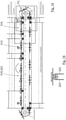
- FIG. 1A and 1B shows a highly schematized representation of a packaging device according to the invention with a forming unit according to the invention in a side view and top view.
- the Figure 1B an alternative embodiment variant of the packaging device according to FIG Figure 1A , which is why the same features are given the same reference numbers, but are preceded by the number "1".
- a band-shaped film F is unwound from a film coil Fc.
- an aluminum foil an aluminum foil that is laminated with a sealing layer, for example, malleable paper that is optionally also laminated with a sealing layer, or plastic film can be used as the foil material.
- the film does not have to be flexible at room temperature, but can also only have the flexibility shown in higher temperature ranges.
- the film can already be thermally acted on by heating elements or the like in the unwinding area A or in an adjoining area B in the conveying direction RF, referred to here as the calming area B.
- plastic plates or the like to convey material instead of a foil coil. These can likewise be thermally heated in the first region A or in the region B adjoining it in the conveying direction R F and thereby made deformable.
- the foil coil is pushed onto a mandrel.
- this is mounted on one side so that a quick change can take place when the film ends.
- the film coil is against pushed a stop.
- the roll can be fixed with a second clamping ring.
- After unrolling a film loop (in the unrolling area A of the 1 shown) the film F is fed into the packaging device 10. This is necessary to keep the film free of tension, otherwise it could tear.
- the loop size or the sagging of the film F in the unwinding area A can be determined, for example, using a sensor.
- the film F should calm down when running in a straight line. For this purpose, it is guided laterally over a predetermined length, so that slight inclinations can be corrected when the film is fed in.
- a print mark sensor can be provided at the end of the calming area B, which detects the position of the film passing through. Depending on the position, the film can then be accelerated or decelerated. In the embodiment shown, this is done with the help of two foil rollers (in the calming area B of the 1 shown schematically on the left), between which the film F runs. The conveying speed of the film F in the area of these film rollers can be passed on to a downstream conveying unit 18 of the packaging device 10 as a reference speed.
- the film can also be braked or accelerated via fixing belts or belt belts 186, 188, which can run above the conveyor unit 18, for example (cf. also Figure 1B ).
- the film F is then conveyed through the packaging device 10 via the conveying unit 18 .
- the film F runs through the following units together with the conveyor unit 18: forming unit 12, unit for fitting and folding over 14, and closing unit 16.
- the conveyor unit 18 comprises a number of film carriers 20, which are continuously conveyed through the packaging device 10 via a circulating conveyor system, for example a conveyor belt, a conveyor chain or a rotating conveyor plate, which is not covered by the invention in an embodiment.
- a conveyor chain 22 is provided, to which the film carriers 20 are attached.
- two adjacent film carriers 20 can be connected to one another in pairs via a folding joint 20a.
- the film carrier 20, which is running in front for example, to be firmly connected to the circulating conveyor system, i.e., for example, the conveyor chain 22, while the film carrier 20 that is trailing in each case, which can be folded over onto the film carrier 20 running in front via the folding joint 20a (indicated by the two folding arrows K), can be detachably attached to this.
- the film carrier 20 that is trailing in each case which can be folded over onto the film carrier 20 running in front via the folding joint 20a (indicated by the two folding arrows K)
- the individual film carriers have, for example, suction bores through which the film can be sucked.
- the vacuum can be generated by a vacuum fan or the like mounted under the film carrier (not shown).
- the film pieces can be embossed in the forming unit 12 by cutting and/or shaping into the film carrier 20, ie connected to it in a form-fitting manner. This solution is described below with reference to the Figures 2A to 2C referred to more closely.
- the guides may comprise thin sheets or belts 186, 188 fixedly mounted to the machine frame.
- the belts 186, 188 run at the same speed as the film carriers 20.
- the film runs under these guides and above the film carrier.
- the guide is recessed accordingly in the respective processing units, so that they cannot collide with the processing tools.
- the film F runs between the respective belts 186, 188 and the conveyor unit 118 and is pressed by the belts against the film carrier 120 in such a way that it cannot slip or fly away during transport.
- a separate guide is no longer absolutely necessary.
- the formed package is held securely to the film carrier by gravity (due to the product being picked up).
- the essentially planar foil F is segmented, ie a piece of foil is cut off from the foil web. This is achieved with the aid of a segment cutting blade 34 which is able to move relative to the foil carrier 20 in a lifting movement Z.
- the cut piece of foil or foil semi-finished product FH rests on the continuously moving foil carrier 20 and moves into the processing area of the forming tool, which is composed of a forming punch 30 and a corresponding die 32 .
- a hold-down device can also be provided (not shown here), which clamps the film F between itself and the bearing surface of the film carrier 20 .
- the forming process is carried out before the film is segmented.
- the segment blade 34a upstream of the forming die 30 in the conveying direction RF is not used for this purpose, but rather a cutting blade 34b downstream of it.
- the preformed film whether segmented or not, can also be end-cut, ie the preformed semi-finished film FH with the desired end contour is cut out of the film with the aid of a end cutting blade 36 shown schematically.
- the step of final cutting takes place in the area of the closing unit 16, ie after the loading and folding of the semi-finished molds.
- the end cutting step is carried out in the area of the forming unit 12, the end cutting can be carried out in the same stroke, i. H. be carried out with the same stroke movement Z, in which the shaping was carried out.
- a drive that in the exemplary representation of 1 is provided with the reference number 24 and allows movement in the X direction.
- the drive 24 is connected via force application points 26 and 28 to the carriage of the respective machining tools.
- processing tools can also be reset by means of an elastic reset unit (not shown).
- the unit for loading and folding 14 is in the illustrated embodiment 1 only indicated.
- the preformed semi-finished film FH can be manually or automatically loaded with food products or products of all kinds in this area 14, ie every second semi-finished film FH is loaded in the illustrated embodiment.
- the unequipped semi-finished film products are then folded over onto the equipped semi-finished film products by means of the foldable film carrier 20, with the product itself being used to center the folded semi-finished film product FH and the now emptied film carriers can then be folded back onto the conveyor system in a further folding step will.
- the two semi-finished foils FH are brought together and form a common housing for the product contained therein (cf. e.g. also Figure 7A ).
- the closing unit 16 the two semi-finished film products are connected to one another.
- a combination of these two methods is also conceivable.
- the mechanical closure reference is made, inter alia, to a method according to the publication AT 221906B referred.
- a thermal process reference is made, for example, to publication DE 1 211 913 B referred.
- a combined method is, for example, from the publication U.S. 2012/0204412 A1 known in connection with the joining of metal components in automobile construction.
- a closing mold 38 is shown by way of example as the upper tool part with a counter-holder 40 as the lower tool part.
- the packaged products can finally be removed in a removal area E following the conveying direction R F .
- a removal area E following the conveying direction R F .
- different solutions are conceivable, for example, they can fall onto a chute or the like as the film carrier rotates. Alternatively, they can of course also be removed manually or automatically.
- FIGS. 2A and 2C show two variants of a tool system according to the invention for crimping or caulking and thus fixing a semi-finished film F H on a film carrier 20. Accordingly, the same features are provided with the same reference symbols, but in the second embodiment these are preceded by the number "1".
- FIG. 2A and 2B shows a three-part tool system 42 according to the invention with an upper tool part 64, a lower tool part 70 and a foil carrier 20, the foil carrier 20 forming the middle part of the tool.
- the bearing surface of the film carrier 20 is formed by a functional ring 48, which can be covered with different functional sections.
- One of these functional sections can be seen in the inclined recess 48a, into which a forming die 46 of the tool upper part 64 can dip.
- a circumferential foil flange F F rests at least partially in the area of the recess 48 .
- the forming stamp 46 is now inserted into the recess 48a with its forming tip 44, the partially resting foil flange FF is inserted into the recess 48a by this, which leads to caulking of the foil flange FF . Because the recess 48a is at an angle ⁇ (cf. Figure 2B ) is inclined to the film support plane and that this deformation of the film flange F F is carried out on two opposite sides of the circumferential flange F F , a secure form-fitting fixation of the semi-finished film FH on the film carrier 20 is achieved.
- ⁇ cf. Figure 2B
- Figure 2C differs from only that Figure 2A that the lower tool part 170 is accommodated in a different way in the middle part of the tool, ie the film carrier 120 .
- This is intended to show in particular that this specific solution for crimping or Caulking of the semi-finished film on the film carrier for better fixation can be seen separately from the specific configuration of the film carrier and the tool center part 170 .
- This aspect of the invention is of course also conceivable detached from the remaining aspects of the invention, in particular from the design of the tool system, the arrangement for molding with a hold-down device and the specific molding process, and can accordingly also be used in differently designed devices or in connection with a single-stage molding process come into use.
- Figure 1 shows the forming unit 12 of the packaging device 10 according to the invention in more detail.
- This is also designed as a three-part tool system with an upper tool part in the form of the forming punch 30 , with a lower tool part in the form of the die 32 and a central tool part in the form of a film carrier 20 .
- a film F lies on the film carrier 20 and is to be shaped with the aid of the forming punch 30 and the associated die 32 .
- the film carrier 20 has a central through-opening 50 which forms a receiving area for the lower tool part, ie the matrix 32 .
- orientation recordings 52 are also provided, in which corresponding projections 54 on the die 32 are received and can be secured against twisting of the die relative to the film carrier.
- the presentation of the film carrier 20 was omitted to simplify the presentation.
- the die 32 has a mold recess 56 on its shaping upper side, the inner contour of which is essentially adapted to a shaping outer contour 32 of the stamp 30 .
- it has a holder receptacle 58 on its non-forming underside for connection to a lifting movement Z (cf. 1 ) provided introductory holder.
- the presentation of the film carrier 20 was omitted to simplify the presentation.
- the die 32 has a mold recess 56 on its shaping upper side, the inner contour of which is essentially adapted to a shaping outer contour 62 .
- a holder mount 58 for connection to a lifting movement Z (cf. 1 ) provided introductory holder.
- a first step (cf. Figure 10A ) the punch 30 and the die 32 are moved towards one another to form the film, i.e. the punch 30 is in particular moved into the die 32 to a certain extent, with the minimum distance between the outer punch contour 62 and the inner die contour 56 being greater when they are moved towards one another than the thickness of the foil to be deformed.
- the film has already been preformed into a semi-finished film FH, with a film flange FF radially surrounding the preformed area of the semi-finished film FH within the die 32 resting on the underside of a hold-down device 90 .
- the hold-down device 90 has a minimum distance from the bearing surface 92 of the shaping unit 12 in the first molding step, so that the film flange FF is not clamped between the bearing surface 92 and the contact surface of the hold-down device 90.
- this results in reduced friction and thus reduced stress on the film, which means that the risk of the film tearing can be reduced even when using a comparatively thin film.
- a further molding step in the illustration shown a final second molding step
- the hold-down device 90 and the punch 30 brought into the usual molding position in which the distance from the respective contact or molding partners, i. H. the contact surface 92 or the mold recess 56, is less than the minimum distance in the first molding step, for example essentially corresponds to the film thickness of the film to be shaped.
- the hold-down device 90 is held displaceably by means of an elastic spring system 94 and can be held at the desired distance from the bearing surface 92, for example by means of spacers (spacers, spacer projections or the like) which are not shown.
- one and the same pair of punches and dies is used for the two-stage molding process.
- the die 32 or 132 has an elastic insert 60 or 160, which is intended to serve for improved reshaping of, in particular, those mold areas (critical area CA) that have strong contour transitions.
- FIG. 7A to 7C a further exemplary embodiment of a tool system according to the invention of the packaging device is shown.
- This relates to the final cutting of the semi-finished film F H using a cutting knife 66 with a circumferential cutting contour.
- the cutting knife 66 is attached to the tool upper part 64 and is moved with a lifting movement in direction Z onto the tool middle part in the form of the foil carrier 20 .
- the film carrier 20 has an additional functional ring 48 which rests on the film carrier 20 and forms the bearing surface for the film semi-finished products or their peripheral film flanges F F .
- a circumferential cutting groove 82 is provided on the functional ring 48 as a functional section, into which the cutting blade 66 can dip. In principle, it is also conceivable to form the cutting groove 82 directly on the foil carrier 20 .
- a hold-down device 68 is also shown, which is able to clamp the film flanges F F lying against one another of the semi-finished film products FH lying on top of one another against the functional ring 48 .
- the hold-down device 68 is resiliently mounted in a known manner on the tool upper part 64 in such a way that it comes into clamping contact, preferably against the foil flanges F F , before the cutting blade 66 is able to enter the cutting groove 82 .
- Figure 7C differs from that of the only in this respect Figure 7A that the lower tool part 170 is received directly on the foil carrier 120 . Accordingly, the features in the Figures 7A and 7C given the same reference signs, but these in Figure 7C preceded by the digit "1". The one related to the Figures 7A to 7C The aspect described is of course also conceivable in connection with such tool systems which are not designed in three parts and in which, in particular, the film carrier does not form part of the tool system.
- the final cutting step can take place before the mechanical and/or thermal connection of the semi-finished foils FH or afterwards.
- the end cutting can be done before the connection, while with a thermal connection, for example by sealing, the end cutting can be done both before and after the connection.
- the sealing is carried out before the folding or flanging.
- a sealing layer is only applied on one side.
- Figures 8A to 8D show an example of how a floating mounting of at least one of the tool parts of a tool system according to the invention can be designed, which enables better alignment of the tool parts during a machining step. So is in Figure 8A a tool system with an upper tool part 64 and a lower tool part 70 is shown as an example. To simplify the illustration, the middle part of the tool is not shown here.
- the tool upper part 64 is connected via an adapter plate 72 to a push rod 84 that initiates the machining movement.
- the push rod 84 and the adapter plate 72 are firmly connected to one another, for example formed in one piece, welded or joined together in some other way.
- the tool upper part 64 is attached to the adapter plate 72 by means of four bolts 74 .
- a clearance of 0.5 mm, for example, is provided between the respective bolts 74 and the associated receptacle of the adapter plate 72, which enables a corresponding tolerance compensation in the event of positioning errors between the upper tool part 64 and the lower tool part 70. This is particularly evident in the detailed representation of the Figure 8D refer to.
- the floating bearing enables tolerance compensation. in several directions transverse to the machining movement, in this case in a plane perpendicular to the machining direction.
- both the upper tool part and the lower tool part can be provided with a corresponding floating bearing.
- bevels allow the individual tool parts to be brought together and positioned relative to one another more easily.
- Other measures such as guide projections, which are able to dip into corresponding recesses on a different one of the tool parts in each case, in order to ensure secure positioning during the machining process, are of course also conceivable.
- FIGS. 9A to 9C finally show a further exemplary embodiment of a three-part tool system of the packaging device according to the invention.
- this involves a positioning device 76, by means of which a protruding edge of the already joined packaging in the form of the semi-finished film F H is positioned at a predetermined angle can to simplify the handling of the joined packaging.
- a circumferential forming area 80 or 180 is provided on the lower tool part 70 or the film carrier 20 or an associated functional ring 48, into which a corresponding forming die 78 or 178 can immerse in order to place the protruding edge of the semi-finished film FH accordingly.
- an angle of inclination of ⁇ is provided on the forming stamp 78 and the corresponding forming area 80 .
- FIGS 9A and 9C show two variants for a tool system according to the invention for creating. Accordingly, the same features are given the same reference numerals, but in the second embodiment these are preceded by the numeral "1".
- Figure 9C differs from only that Figure 9A that the lower tool part 170 is accommodated in a different way in the middle part of the tool, ie the film carrier 120 .
- This is intended to show in particular that this specific solution for applying the film edge is to be viewed independently of the specific design of the packaging device, the tool system and in particular the film carrier 120 and the tool center part 170 .
- the application device 76 for applying the protruding edge can be designed in such a way that the protruding edge is not applied completely, but that a portion of the edge remains.
- the contact contour of the packaging would not be circular, but rather open at the point where the edge should not be placed.
- the contact edge or the contact form is interrupted and the edge or the tear-off aid protrudes outwards. This results in a user-friendly tear-off aid that protrudes from the packaged product in such a way that a user can easily grasp it.
- the feed device 76 can also be arranged outside the machine, from where it can be brought to the desired location by means of suitable devices, in particular handling devices such as multi-axis robots, linear feed devices or the like.
- the application device 76 can also be designed in such a way that it adjusts to different contours of the packaging or can be adjusted to different contours of the packaging. This can be achieved, for example, by means of suitable resilient or flexible elements that can adapt to different contours.
- FIG. 11 shows in a very schematic way an alternative embodiment of the tooling system of the packaging device.
- the features are off Figure 1A corresponding features are provided with the same reference numerals, but preceded by the number "2".
- the conveyor unit 218 according to 11 designed at least in sections thereof as a discontinuously operating conveyor unit 218.
- the conveying unit 218 is discontinuous in the area of the molding unit 212, ie it operates discontinuously in the area of the molding unit 212 or is operated discontinuously in the area of the molding unit 212. This simplifies the processing of the semi-finished film F H using the tool system and reduces wear and tear on the tool system.
- the conveyor unit 218 has a linear drive device 223, indicated very schematically, for the individual tool center parts, which can be designed and operated in a manner known per se.
- the linear drive device 223 makes it possible to achieve very high speeds when transporting the semi-finished film products F H .
- each tool center part can be controlled separately, so that it is very easy to stop the tool center parts in the area of the forming unit 212, so that the forming of the semi-finished film FH can be carried out more easily than in a completely continuous operation.
- the tool centers can be continuous and possibly at higher speeds and/or accelerations than in the referenced figures Figures 1A and 1B described embodiments are moved, so that there are no delays in the processing of the film F.
- these can of course be synchronized with one another, for example by means of a control device, not shown, in order to ensure trouble-free operation.
- the linear drive device 223 other drives can also be used which enable discontinuous operation of the conveyor unit 218 at least in sections.
- the at least partial use of pneumatic or hydraulic cylinders is also possible.
- the central drive 24 provided in the continuously operating conveyor unit 18 or 118 would be omitted or replaced by the linear drive device 223 .
- FIG. 12A and 12B an alternative embodiment of a securing arrangement 300 for fixing the semi-finished film F H is shown.
- the securing arrangement 300 has a clamping element 301 and at least one spring element 302 which presses the clamping element 301 in the direction of the film carrier 20 , 120 .
- respective clamping elements 301 are provided on two opposite sides of the tool center part, which are pressed in the direction of the film carrier 20, 120 with two spring elements 302 each.
- the spring elements 302 are leg springs, which are supported with one leg on the tool center part and with the other leg on the clamping element 301 .
- the securing arrangement 300 can have a link guide or the like, not shown, which is in operative connection with the at least one clamping element 301 or preferably with both clamping elements 301 in such a way that by means of the link guide an opening of the respective Clamping element 301 can be effected against the force of the spring element 302. A targeted opening of the security arrangement 300 is thereby achieved.
- the link guide can be connected to the clamping elements 301 via a plunger (not shown), which acts on the clamping elements 301 and opens them against the force of the spring elements 302 .
- clamping elements 301 In a way that is not shown, however, it is also conceivable for the clamping elements 301 to be opened or released against the force of the spring elements 302 by means of servomotors or other suitable devices.
- a further possibility for securing the semi-finished film F H can be that the semi-finished film F H of the film packaging is secured during transport on the film carrier 20, 120 by folding the film edges onto the film carrier 20, 120.
- the film edges are placed against the film carrier 20, 120, for example at an angle of 90°, so that they cannot slip on the film carrier 20, 120 during transport.
- the semi-finished film FH is not pierced, but only folded over at its edges. A combination of crimping and turning over the edges is also possible.
- the at least one punch 230 and the at least one die 232 are moved relative to one another to form the film F, with both the punch 230 being moved in the direction of the die 232 and the die 232 being moved in the direction of the punch 230.
- the punch 230 and the die 232 are moved toward each other.
- the stamp 230 and the die 232 can be moved completely independently of one another, for which purpose suitable drives can be used.
- the film carrier 220 remains stationary.
- the die 232 can be moved in the direction of the punch 230 in such a way that the die 232 comes into contact with the film F before the punch 230 reaches a lower reversal point.
- the matrix 232 is in contact with the foil F, the latter begins to deform so that it is pre-formed by the contact with the matrix 232.
- the foil F is pressed upwards in this way, which leads to a further reduction in the required hold-down forces exerted by a hold-down device 290 .
- the matrix 232 can also be used to fix the position of the film F before it is deformed, which results in an improvement in the position and orientation of the printed image.
- the die 232 does not have to be contoured exactly like this be like in the Figures 13A, 13B and 13C shown and can also be used with smooth or smoother shapes than the shape shown.
- the stamp 230 can also be controlled in such a way that, after dipping into the film carrier 220, it is moved back again in order to support the described pre-shaping of the film F by the die 232. This also results in the possibility of realizing more complex shapes of the film packaging, since the film F can be shaped from two sides.
- the retraction of the punch 230 also allows the sheet material to move toward the die 232 to facilitate deformation by the die 232 as described.
- the described upward movement of the punch 230 can also be triggered or supported by the die 232 if the force acting on the die 232 is higher than the force acting on the punch 230 .
- FIG. 14 shows in a schematic way a further alternative embodiment of the tooling system of the packaging device. Again, the characteristics are off Figure 1A corresponding features are provided with the same reference numerals, but preceded by the number "3".
- the conveyor unit 318 according to 14 In contrast to the continuously operating conveyor unit 18 according to Figure 1A or the continuously operating conveyor unit 118 according to Figure 1B is the conveyor unit 318 according to 14 , similar to the conveying unit 218 according to FIG 11 , formed at least in sections thereof as a discontinuously operating conveyor unit 318.
- the conveyor unit 318 is similar to the conveyor unit 218 according to FIG 11 , is designed discontinuously in the area of the forming unit 312, ie it works discontinuously in the area of the forming unit 312 or is operated discontinuously in the area of the forming unit 312, which in turn simplifies the processing of the semi-finished foils FH using the tool system and reduces wear on the tool system.
- the conveyor unit 318 still has sections in which the discontinuously operated sections are synchronized with the continuously operated sections, ie in which a transition from the discontinuously operated sections to the continuously operated sections is realized.
- the continuously operated sections of the conveyor unit 318 are shown with solid lines, the sections in which the synchronization takes place with short dashed lines and the discontinuously or cyclically operated sections of the conveyor unit 318 with long dashed lines.
- the conveying unit 318 has several, in the present case designed as a belt 323, limp drive elements which are used to form the continuously operated sections, the discontinuously operated sections and the sections in which the Synchronization of the intermittently operated sections with the continuously operated sections takes place, can be used.
- the flexible drive elements could also be designed as a chain or in some other suitable way.
- the belts 323 are passed around respective pulleys, with positive engagement between the belts 323 and the pulleys being preferred.
- the belts 323 can thus be, for example, toothed belts, cam belts or the like.
- the flexible drive elements i.e. the belts 323 in the present case, enable a particularly simple transition between the continuously and discontinuously operated sections of the conveyor unit 318, which not only allows very high speeds to be achieved when transporting the semi-finished film products FH , but also safe operation of the conveyor unit 318 is guaranteed.
- the flexible drive elements can be controlled by respective servomotors in order to ensure that the process carried out with the conveyor unit 318 or the method carried out with the same is always under control.
- the flexible drive elements can be controlled in any desired manner by the servomotors, so that any desired synchronization between the movement sequences is possible, in particular the desired synchronization.
- asynchronous motors with corresponding electronic control can also be used.
- each tool center part can be controlled separately, so that the tool center parts can be stopped very easily in the area of the forming unit 312, as a result of which the forming of the semi-finished foils FH can be carried out more easily than in a completely continuous operation.
- the straps 323 can be provided with suitable elevations, depressions or the like on their sides facing the same.
- the tool centers can be continuously and possibly at higher speeds and/or accelerations than in the referenced figures Figures 1A and 1B described embodiments are moved, so that there are no delays in the processing of the film F.
- the central drive 24 provided for the continuously operating conveyor unit 18 or 118 could in turn be omitted.
- the tool system described can also be used in areas other than packaging.
Description
Die Erfindung betrifft ein Werkzeugsystem zur Verwendung in einer Verpackungsvorrichtung zur Verpackung von Lebensmittelprodukten, insbesondere von Schokoladenhohlkörpern, mittels einer Folienverpackung, sowie eine entsprechende Verpackungsvorrichtung.The invention relates to a tool system for use in a packaging device for packaging food products, in particular hollow chocolate bodies, by means of foil packaging, and a corresponding packaging device.
Verpackungsvorrichtungen weisen in der Regel mehrere Bearbeitungseinheiten zur Bearbeitung der Verpackung auf. So beschreibt beispielsweise die Druckschrift
Die
In der
Aus der
Eine Maschine zum Verpacken von Gegenständen ist aus der
Die
In der
Eine Vorrichtung zum Herstellen von Behältern aus einem Blattmaterial mit einer Bedieneinheit zum Verarbeiten des Blattmaterials ist in der
Aus der
Die
Zu Beginn des Verarbeitungswegs weist die Maschine eine Folienbereitstellungseinheit auf, in der ein Foliencoil drehbar aufgehängt ist und mit einem gesteuerten Antrieb diskontinuierlich angetrieben werden kann, um das Abziehen eines Folienbandes vom Foliencoil zu unterstützen. Als nächste Bearbeitungseinheit ist eine Vorschneidestation beschrieben, in der das Folienband durch ein sich gesteuert hebend und senkendes Vorschneidmesser pro Arbeitstakt in vier Folienstücke geschnitten wird.At the beginning of the processing path, the machine has a foil supply unit in which a foil coil is rotatably suspended and can be driven intermittently with a controlled drive in order to support the pulling of a foil strip from the foil coil. A pre-cutting station is described as the next processing unit, in which the foil strip is cut into four pieces of foil per work cycle by a pre-cutting blade that is controlled and raised and lowered.
Die Folienstücke werden anschließend mit Hilfe eines sich in der Horizontalen in Richtung des Verarbeitungsweges hin und her bewegbaren Transferschlittens mit Unterdruckfoliengreifern unter eine Stempelvorrichtung bewegt, die in Richtung des Verarbeitungswegs der Vorschneidestation nachgeordnet als nächste Bearbeitungseinheit vorgesehen ist. In der Stempelvorrichtung werden die Folienstücke zu Folienhalbschalen geformt, fixiert und in einem weiteren Bearbeitungsgang beschnitten. Auf diese Weise erhalten die Folienhalbschalen neben ihrem halbschalenförmigen Körper einen daran angeschlossenen ringartigen Folienflansch.The film pieces are then moved under a stamping device, which is provided downstream of the pre-cutting station in the direction of the processing path as the next processing unit, with the aid of a transfer carriage that can be moved back and forth horizontally in the direction of the processing path. In the stamping device, the foil pieces are formed into foil half-shells, fixed and trimmed in a further processing step. In this way, the foil half-shells have a ring-like foil flange attached to their body in the form of a half-shell.
Mittels eines 3D-Formsaugers, welcher auf einer beweglichen Schlittenvorrichtung aufgehängt ist, wird jede der Folienhabschalen aus der Formmatrize der Stempelvorrichtung herausgenommen, zu einer Wartevorrichtung bewegt und auf dieser abgelegt. Die Wartevorrichtung ist in Richtung des Bearbeitungswegs der Stempelvorrichtung direkt nachgestellt angeordnet und weist der Anzahl der Folienhalbschalen entsprechende Folienhalbschalenaufnahmen auf.By means of a 3D forming sucker, which is suspended on a movable carriage device, each of the film shells is removed from the forming matrix of the stamping device, moved to a waiting device and placed on it. The waiting device is arranged directly downstream of the stamping device in the direction of the processing path and has film half-shell receptacles corresponding to the number of film half-shells.
Weiterhin umfasst die in der Druckschrift
Um den Takttisch zu bestücken ist eine Greifvorrichtung vorgesehen, die mittels konvexer 3D-Formsauger die geformten Folienhalbschalen aus der Wartevorrichtung aufzunehmen und in einer spezifischen Position des Takttisches (Ausgangsposition) in die Folienhaltevorrichtungen abzulegen vermag. Durch Drehung des Takttisches um eine Vierteldrehung werden diese Folienhalbschalen dann in eine Bestückungsposition gebracht, in der die Bestückungsvorrichtung eine der Folienhalbschalen mit einem Lebensmittelprodukt bestückt. In einer nachgeschalteten Klappposition des Takttisches wird dann mittels eines Schwenkarms der Klappeinheit die Haltevorrichtung, welche die unbestückte Folienhalbschale trägt, umgeklappt, sodass nach diesem Klappvorgang durch die Klappeinheit die Flansche der beiden Folienhalbschalen bündig und fluchtend aufeinander aufliegen. Und anschließend werden nach Drehen des Takttisches um wiederum eine Vierteldrehung in die Fügeposition die Folienflansche mittels der Fügeeinheit zusammengefügt.In order to load the indexing table, a gripping device is provided, which is able to pick up the formed half-shells of film from the waiting device by means of convex 3D shaped suction cups and place them in the film holding devices in a specific position of the indexing table (starting position). By rotating the indexing table by a quarter of a turn, these film half-shells are then brought into an assembly position, in which the assembly device equips one of the film half-shells with a food product. In a downstream folding position of the indexing table, the holding device, which carries the empty foil half-shell, is then folded over by means of a swivel arm of the folding unit, so that after this folding process by the folding unit, the flanges of the two foil half-shells lie flush and aligned with one another. And then, after the indexing table has been turned a quarter of a turn into the joining position, the foil flanges are joined together using the joining unit.
In der Ausgangsposition des Takttisches werden die gefügten Folienhalbschalen schließlich von konvexen Greifern aufgenommen, sodass diese zur Produktabführvorrichtung transportiert werden können und eine erneute Belegung der Folienhaltevorrichtungen mit geformten Folienhalbschalen erfolgt.In the starting position of the indexing table, the joined half-shells of film are finally picked up by convex grippers so that they can be transported to the product removal device and the film holding devices are re-occupied with formed half-shells of film.
Die beschriebene Verpackungsvorrichtung hat sich in der Praxis durchaus als gut funktionierende Lösung erwiesen. Allerdings ist ein Nachteil dieser Lösung darin zu sehen, dass zwischen den einzelnen Bearbeitungseinheiten Vorschneidestation, Stempelvorrichtung und Takttisch immer wieder Transportvorrichtungen bzw. Fördereinheiten vorzusehen sind, die einen Transport zwischen den Bearbeitungseinheiten ermöglichen. Hierdurch wird die Komplexität des gesamten Systems signifikant erhöht. Dies wirkt sich zudem auf die Kosten der Verpackungsvorrichtung aus.The packaging device described has proven to be a well-functioning solution in practice. However, a disadvantage of this solution can be seen in the fact that between the individual processing units, the pre-cutting station, the stamping device and the indexing table, transport devices or conveyor units must be provided again and again, which enable transport between the processing units. This significantly increases the complexity of the entire system. This also has an effect on the cost of the packaging device.
Weiterhin kann bei jedem dieser Transportvorgänge durch eine unsaubere Aufnahme oder ein unsauberes Ablegen der Folien-Zwischenprodukte (auch als Folienhalbzeuge bezeichnet) an den einzelnen Bearbeitungseinheiten die Prozessstabilität beeinträchtigt und der Ausschuss erhöht werden. Schließlich handelt es sich bei dem beschriebenen Verpackungsverfahren der
Die Druckschrift
Allgemein ist das Umformen von dünnen Folien (mit oder ohne Beschichtung), beispielsweise aus Aluminium, Papier oder Kunststoff mit einer Dicke von beispielsweise 8µm bis ca. 40 µm kein Tiefziehvorgang, wie er beispielsweise aus der Blechumformung im Automobilbau bekannt ist. Stattdessen handelt es sich dabei um einen Faltvorgang, bei dem die Folie durch einen Stempel in eine Matrize gedrückt wird. Dabei wird sie verfaltet und bildet so ihre endgültige Form. Es finden folglich nur geringfügige Fließvorgänge bis ca. 10% statt, jedoch keine Fließvorgänge, wie sie beispielsweise aus der Blechumformung bekannt sind.In general, the forming of thin foils (with or without coating), for example made of aluminum, paper or plastic with a thickness of, for example, 8 μm to approx. 40 μm is not a deep-drawing process, as is known, for example, from sheet metal forming in automobile construction. Instead, it is a folding process in which the foil is pressed into a die by a stamp. It is folded and thus forms its final shape. As a result, there are only minor flow processes of up to approx. 10%, but no flow processes as are known from sheet metal forming, for example.
Aus dem Stand der Technik, insbesondere der Druckschrift
Der Formvorgang und der Schneidvorgang werden mit der gleichen Vorrichtung bewirkt, die neben einer Matrize am Werkzeugunterteil und einem Stempel am Werkzeugoberteil auch ein Schneidmesser am Werkzeugoberteil und einen elastisch gelagerten Schneidring am Werkzeugunterteil aufweist. Zuerst wird in einem einzigen Arbeitshub das gewünschte Folienstück aus dem Metallband ausgeschnitten und dann umgeformt. Der Stempel ist mehrstufig mit einem Patrizenvorlaufstempel und einem Stauchring ausgebildet. Die Matrizenhohlform, in die der Stempel zur Verformung des Metallbandes eintaucht, ist ebenfalls mit einer gestuften Ausnehmung versehen. Bei dieser geht ein erster konischer Ausnehmungsbereich, der mit seiner Innenkontur der Außenkontur des Patrizenvorlaufstempels entspricht, mit einer Stufe in einen zweiten ringförmigen Ausnehmungsbereich über, der mit seiner Innenkontur der Außenkontur des Stauchrings entspricht.The forming process and the cutting process are effected with the same device which, in addition to a die on the lower part of the tool and a stamp on the upper part of the tool, also has a cutting knife on the upper part of the tool and an elastically mounted cutting ring on the lower part of the tool. First, the desired piece of foil is cut out of the metal strip in a single stroke and then formed. The punch is designed in several stages with a male forward punch and an upsetting ring. The cavity mold, into which the stamp for forming the metal strip dips, is also provided with a stepped recess. In this case, a first conical recess area, the inner contour of which corresponds to the outer contour of the male advance punch, merges with a step into a second annular recess area, the inner contour of which corresponds to the outer contour of the compression ring.
Auch in der
Des Weiteren beschreibt die
Während des Umformvorgangs können zwischen den Formwerkzeugen so hohe Kräfte auftreten, dass die umzuformende Folie reißen kann. Damit dies nicht geschieht, werden in der Praxis ausreichend dicke Folien gewählt, um den Ausschuss in der Produktion gering zu halten. In der Konsequenz steigen die Materialkosten. Zudem sind zum Umformen dickerer Folien höhere Umformkräfte erforderlich, was sich negativ auf die Standzeiten der Maschinen auswirken kann. Weiterhin müssen die Maschinen von vornherein eine höhere Stabilität aufweisen, um höhere Kräfte aufbringen zu können, was zudem die Maschinenkosten in die Höhe treibt.During the forming process, such high forces can occur between the forming tools that the film to be formed can tear. In order to prevent this from happening, sufficiently thick films are selected in practice in order to keep waste in production to a minimum. As a consequence, the material costs increase. In addition, higher forming forces are required to form thicker foils, which can have a negative impact on the service life of the machines. Furthermore, the machines must have greater stability from the outset in order to be able to apply higher forces, which also drives up the machine costs.
Aus der
Die
Eine Ziehpresse zum Ziehen von Verpackungsbehältern aus dünnen Blechen oder Kunststofffolien ist in der
Aus der
Eine Aufgabe der vorliegenden Erfindung besteht darin, bekannte Lösungen aus dem Stand der Technik weiter zu entwickeln, insbesondere um ein Werkzeugsystem zur Verwendung in einer Verpackungsvorrichtung mit einer geringeren Komplexität bereitzustellen.An object of the present invention is to further develop known solutions from the prior art, in particular to provide a tooling system for use in a packaging device with a lower complexity.
Demgemäß schlägt die vorliegende Erfindung ein Werkzeugsystem mit den Merkmalen des Anspruchs 1 vor.Accordingly, the present invention proposes a tool system with the features of
Das erfindungsgemäße Werkzeugsystem nach Anspruch 1 ist zur Verwendung in einer Verpackungsvorrichtung zur Verpackung von Lebensmittelprodukten, insbesondere von Schokoladenhohlkörpern, mittels einer Folienverpackung vorgesehen. Die Verpackungsvorrichtung umfasst dabei, wie in der
Das Werkzeugsystem umfasst erfindungsgemäß zumindest drei Werkzeugteile, nämlich ein Werkzeugmittelteil sowie ein Werkzeugunterteil und ein Werkzeugoberteil, die im Betrieb bearbeitend zusammenzuwirken vermögen. Dabei dient das Werkzeugmitteilteil zur Aufnahme und Förderung von wenigstens einem zu bearbeitenden Folienhalbzeug der Folienverpackung zwischen den einzelnen Bearbeitungseinheiten der Verpackungsvorrichtung. Weiterhin ist erfindungsgemäß vorgesehen, dass das Werkzeugmittelteil mit jeweils wenigstens einem weiteren Werkzeugteil (d. h. dem Werkzeugunterteil oder dem Werkzeugoberteil) des Werkzeugsystems zusammenzuwirken vermag, wobei das weitere Werkzeugteil jeweils ein Werkzeugteil einer der Bearbeitungseinheiten ist, die der Bearbeitung des Folienhalbzeugs von der Aufnahme auf dem Werkzeugmittelteil bis zu seiner Fertigstellung als Folienverpackung dienen. Hierzu weist das Werkzeugmittelteil wenigstens eine Schnittstelle auf, mittels derer es mit wenigstens einem Werkzeugteil jeder dieser Bearbeitungseinheiten kompatibel ist.According to the invention, the tool system comprises at least three tool parts, namely a central tool part and a lower tool part and an upper tool part, which are able to work together during operation. The central part of the tool serves to receive and convey at least one semi-finished film product to be processed from the film packaging between the individual processing units of the packaging device. Furthermore, according to the invention, it is provided that the central tool part is able to interact with at least one further tool part (i.e. the lower tool part or the upper tool part) of the tool system, with the further tool part being a tool part of one of the processing units that is used for processing the semi-finished film from the mount on the central tool part serve as film packaging until it is completed. For this purpose, the tool center part has at least one interface, by means of which it is compatible with at least one tool part of each of these processing units.
Der Vorteil der Erfindung gemäß Anspruch 1 besteht somit darin, dass das Werkzeugunterteil und das Werkzeugoberteil jeweils einer Bearbeitungseinheit zuzuordnen sind, beispielsweise Werkzeugteile einer Schneideinheit, einer Fügeeinheit oder einer Formeinheit bilden, während das Werkzeugmittelteil all diese Bearbeitungseinheiten mit einem aufgenommenen Folienhalbzeug durchläuft und damit ein Umsetzen der Folienhalbzeuge zwischen den einzelnen Bearbeitungseinheiten mit zusätzlichen Transportvorrichtungen, wie dies aus dem Stand der Technik bekannt ist, unnötig macht.The advantage of the invention according to
Dadurch, dass das Werkzeugmittelteil mit wenigstens einem Werkzeugteil jeder dieser Bearbeitungseinheiten kompatibel ist, kann es alle diese Bearbeitungseinheiten zur Bearbeitung des Folienhalbzeugs von der Aufnahme auf dem Werkzeugmittelteil bis zu der Fertigstellung als Folienverpackung durchlaufen, ohne dass ein zusätzliches Umsetzen notwendig wird. Zugleich kann das Werkzeugmittelteil selbst Funktionsträger sein und mit einem der Werkzeugteile zur Bearbeitung des Folienhalbzeugs zusammenwirken.Because the tool center part is compatible with at least one tool part of each of these processing units, it can run through all of these processing units for processing the semi-finished film from being mounted on the tool center part to completion as film packaging, without additional repositioning being necessary. At the same time, the tool center part itself can be a function carrier and interact with one of the tool parts for processing the semi-finished foil product.
Jede Bearbeitungseinheit der Verpackungsvorrichtung, die im Sinne der vorliegenden Erfindung zur Bearbeitung der Folienverpackung dient, stellt somit ein eigenes erfindungsgemäßes Werkzeugsystem dar, mit wenigstens einem Werkzeugunterteil und einem Werkzeugoberteil, die der Bearbeitungseinheit zugeordnet sind, sowie einem Werkzeugmittelteil, das zur Bearbeitung des aufgenommenen Folienhalbzeugs in die Bearbeitungseinheit verbracht und im Anschluss daran aus dieser hinaus gefördert werden kann.Each processing unit of the packaging device, which is used within the meaning of the present invention for processing the film packaging, thus represents a separate tool system according to the invention, with at least one lower tool part and one upper tool part, which are assigned to the processing unit, as well as a central tool part, which is used for processing the film semi-finished product received in the processing unit can be brought and then promoted from this out.
Im Zusammenhang mit der vorliegenden Erfindung wird durchgängig der Begriff Folienverpackung verwendet. Die Folie kann dabei aus Kunststoffmaterialien, wie beispielsweise PVC, metallischen Materialien, wie beispielsweise Aluminium, oder aus Verbundwerkstoffen bestehen. Die Folie muss zudem im Ausgangszustand, d. h. bei Raumtemperatur, nicht flexibel sein, sondern kann eine gewisse Steifigkeit aufweisen, und zur besseren Bearbeitung kontinuierlich oder einmalig erwärmt werden.In connection with the present invention, the term film packaging is used throughout. The foil can consist of plastic materials such as PVC, metallic materials such as aluminum, or composite materials. The film must also be in its initial state, i. H. at room temperature, not flexible but may have some rigidity, and heated continuously or once for better processing.
Weiterhin ist vorgesehen, dass das Werkzeugmittelteil mittels einer Fördereinheit angetrieben werden kann, wobei das Werkzeugmittelteil insbesondere einen Folienträger umfassen kann, dem wenigstens ein Folienhalbzeug zugeordnet ist.Furthermore, it is provided that the tool center part can be driven by means of a conveyor unit, wherein the tool center part can in particular comprise a foil carrier, which is assigned at least one semi-finished foil product.
Besonders vorteilhaft ist es dabei, wenn die Fördereinheit zumindest in Abschnitten derselben als kontinuierlich arbeitende Fördereinheit ausgebildet ist.It is particularly advantageous if the conveyor unit is designed as a continuously operating conveyor unit, at least in sections thereof.
Durch den Antrieb des Werkzeugmittelteils mittels einer kontinuierlichen Fördereinheit kann ein kontinuierlicher Betrieb einer entsprechenden Verpackungsvorrichtung, deren Bearbeitungseinheiten als Werkzeugsysteme gemäß der Erfindung ausgebildet sind, bereitgestellt werden. Hierdurch wird eine verbesserte Taktzeit erreicht, was neben dem Vorteil eines geringeren Ausschusses insbesondere einen höheren Output ermöglicht.By driving the central part of the tool by means of a continuous conveyor unit, a continuous operation of a corresponding packaging device, the processing units of which are designed as tool systems according to the invention, can be provided. This achieves an improved cycle time, which, in addition to the advantage of less rejects, enables a higher output in particular.
Zusätzlich ist die Fördereinheit zumindest in Abschnitten derselben als diskontinuierlich arbeitende Fördereinheit ausgebildet. Auf diese Weise kann insbesondere das Formen der Folienhalbzeuge vereinfacht werden, da die sich relativ zueinander bewegenden Werkzeugteile beim Umformen nicht bewegt werden müssen, wohingegen das weniger kritische Beladen der Folienträger während eines Transportvorgangs erfolgen kann.In addition, the conveyor unit is designed as a discontinuously operating conveyor unit, at least in sections of the same. In this way, the forming of the semi-finished film products can be simplified in particular, since the tool parts that move relative to one another do not have to be moved during forming, whereas the less critical loading of the film carrier can take place during a transport process.
Wenn dabei die Fördereinheit eine Linearantriebseinrichtung für das Werkzeugmittelteil aufweist, so ist eine besonders dynamische Bewegung der Folienträger möglich und es ergibt sich eine sehr hohe Flexibilität bezüglich des Betriebs der Fördereinheit.If the conveyor unit has a linear drive device for the tool center part, a particularly dynamic movement of the film carrier is possible and there is a very high level of flexibility with regard to the operation of the conveyor unit.
Weiterhin kann vorgesehen sein, dass wenigstens ein Werkzeugteil des Werkzeugsystems, insbesondere das Werkzeugunterteil und/oder das Werkzeugoberteil, in wenigstens einer Richtung quer zur Bearbeitungsrichtung schwimmend gelagert ist. Insbesondere kann das wenigstens eine Werkzeugteil des Werkzeugsystems auch in einer Ebene quer, beispielsweise senkrecht, zur Bearbeitungsrichtung schwimmend gelagert sein.Provision can furthermore be made for at least one tool part of the tool system, in particular the lower tool part and/or the upper tool part, to be mounted in a floating manner in at least one direction transverse to the machining direction. In particular, the at least one tool part of the tool system can also be mounted floating in a plane transverse, for example perpendicular, to the machining direction.
Bedingt durch das mehrteilige Werkzeugsystem ist es notwendig, in den einzelnen Bearbeitungseinheiten die Werkzeugteile für eine saubere und sichere Bearbeitung sehr genau zusammen zu führen. Um eine leichte Fehlpositionierung der Werkzeugteile zueinander auszugleichen, kann eine schwimmende Lagerung bei einem oder mehreren der Werkzeugteile des Werkzeugsystems vorgesehen sein. Insbesondere kann beispielsweise vorgesehen sein, dass das Werkzeugmittelteil das führende System darstellt, d. h. die Referenz, und dass das Werkzeugunterteil und das Werkzeugoberteil sich an dem Werkzeugmittelteil ausrichten. Bei dieser Ausführungsform kann die schwimmende Lagerung an dem Werkzeugunterteil und/oder dem Werkzeugoberteil vorgesehen sein.Due to the multi-part tool system, it is necessary to bring the tool parts together very precisely in the individual machining units for clean and safe machining. In order to compensate for a slight incorrect positioning of the tool parts in relation to one another, a floating bearing can be provided for one or more of the tool parts of the tool system. In particular, it can be provided, for example, that the tool center part represents the leading system, i. H. the reference, and that the die bottom and die top align with the die center. In this embodiment, the floating bearing can be provided on the lower tool part and/or the upper tool part.
Diese kann beispielsweise mit Hilfe von einer Adapterplatte erreicht werden, die mit dem Werkzeugunterteil bzw. dem Werkzeugoberteil derart verbunden ist, dass sie eine Relativbewegung quer zur Bearbeitungsrichtung des Werkzeugs zulässt. Die Bearbeitungsrichtung bezeichnet dabei die Richtung, in welche die Werkzeugteile, d. h. insbesondere die zusammenwirkenden Werkzeugteile des Werkzeugsystems bei einem Bearbeitungsschritt bewegt werden, um eine Bearbeitung des Folienhalbzeugs zu ermöglichen. Im Falle einer Formeinheit oder einer Schneideinheit kann dies insbesondere eine Hubbewegung sein.This can be achieved, for example, with the aid of an adapter plate, which is connected to the lower part of the tool or the upper part of the tool in such a way that it allows a relative movement transverse to the machining direction of the tool. The processing direction describes the direction in which the tool parts, i. H. in particular the interacting tool parts of the tool system are moved during a processing step in order to enable processing of the semi-finished film. In the case of a forming unit or a cutting unit, this can in particular be a lifting movement.
Um ein Zusammenführen der Werkzeugteile des Werkzeugsystems während eines Bearbeitungsschrittes zu erleichtern, kann ferner vorgesehen sein, dass wenigstens ein Werkzeugteil, insbesondere das Werkzeugunterteil und/oder das Werkzeugoberteil, Fügeschrägen aufweist, bzw. aufweisen. Weiterhin kann vorgesehen sein, dass alternativ oder zusätzlich zu den Fügeschrägen, Führungshilfen, beispielsweise in Form von einer vorspringenden Struktur an einem der Werkzeugteile, die in eine korrespondierende Aufnahmestruktur an einem anderen der Werkzeugteile einzutauchen vermag, vorgesehen sind, um eine zuverlässige Ausrichtung der Werkzeugteile während eines Bearbeitungsschrittes sicherzustellen.In order to make it easier to bring the tool parts of the tool system together during a machining step, it can also be provided that at least one tool part, in particular the lower tool part and/or the upper tool part, has or have bevels. Furthermore, it can be provided that alternatively or in addition to the joining bevels, guide aids, for example in the form of a projecting structure on one of the tool parts, which can dip into a corresponding receiving structure on another of the tool parts, are provided in order to ensure reliable alignment of the tool parts during ensure a processing step.
Gemäß einer Weiterbildung der Erfindung kann vorgesehen sein, dass das Werkzeugunterteil und/oder das Werkzeugoberteil einer Bearbeitungseinheit zumindest abschnittsweise entlang der Förderrichtung des Werkzeugmittelteils hin und her bewegbar sind. Auch diese Maßnahme dient insbesondere dazu, einen kontinuierlichen Betrieb einer solchen Verpackungsvorrichtung zu ermöglichen, die als Bearbeitungseinheiten Werkzeugsysteme gemäß der Erfindung nutzt. So erfolgen die Bearbeitungsschritte Formen, Schneiden und Fügen in der Regel innerhalb eines gewissen Zeitfensters, innerhalb dessen eine Relativbewegung zwischen dem Werkzeugmittelteil und den Werkzeugunter- und -oberteilen nachteilig wäre. Somit muss zumindest für die Zeitdauer des jeweiligen Bearbeitungsschritts das Werkzeugmittelteil relativ zu dem Werkzeugunterteil und Werkzeugoberteil der Bearbeitungseinheit stillstehen.According to a development of the invention, it can be provided that the lower tool part and/or the upper tool part of a machining unit can be moved back and forth at least in sections along the conveying direction of the central tool part. This measure also serves in particular to enable continuous operation of such a packaging device that uses tool systems according to the invention as processing units. The processing steps of forming, cutting and joining generally take place within a certain time window, within which a relative movement between the tool center part and the lower and upper tool parts would be disadvantageous. Thus, at least for the duration of the respective machining step, the tool center part must be stationary relative to the lower tool part and the upper tool part of the machining unit.
Im Stand der Technik wird ein diskontinuierlicher Betrieb vorgeschlagen, bei dem beispielsweise der Takttisch (
Gemäß der Weiterbildung der Erfindung kann durch die Bewegbarkeit der Werkzeugteile einer Bearbeitungseinheit entlang der Förderrichtung des Werkzeugmitteilteils (zumindest über eine vorgegebene Streckenlänge) ein kontinuierlicher Betrieb ohne unerwünschte Stillstandszeiten erreicht werden.According to the development of the invention, the mobility of the tool parts of a machining unit along the conveying direction of the central tool part (at least over a predetermined distance) allows continuous operation to be achieved without undesired downtimes.
Der Antrieb des Werkzeugmittelteils kann dabei beispielsweise mit einer Geschwindigkeit von 20 m/min bis zu 30 m/min laufen. Selbstverständlich sind jedoch auch Vorrichtungen denkbar, bei denen der Antrieb mit einer höheren Geschwindigkeit als 30m/min oder mit einer niedrigeren Geschwindigkeit als 20m/min läuft.The drive of the tool center part can run, for example, at a speed of 20 m/min up to 30 m/min. Of course, however, devices are also conceivable in which the drive runs at a speed higher than 30 m/min or at a speed lower than 20 m/min.
Je nach Bearbeitungszeit in einer Bearbeitungseinheit kann an der Geschwindigkeit, mit der der Antrieb des Werkzeugmittelteils läuft, auch die zurücklegbare Streckenlänge für das jeweils mitzubewegende Werkzeugteil der Bearbeitungseinheit, d. h. das Werkzeugunterteil und/oder das Werkzeugoberteil, bemessen werden. Die Rückförderung der in Förderrichtung des Werkzeugmittelteils mit diesem bzw. diesen während des Bearbeitungsvorgangs mitbewegten Werkzeugteil(en) der Bearbeitungseinheit kann dabei mittels eines separaten Antriebs oder beispielsweise über eine Rückstelleinrichtung erfolgen, die insbesondere einen elastischen Mechanismus zur Rückführung nutzt. Denkbar hierfür sind beispielsweise Spiralfedern oder dergleichen.Depending on the machining time in a machining unit, the speed at which the drive of the tool center part runs can also determine the distance that can be covered for the tool part of the machining unit to be moved, i. H. the lower part of the tool and/or the upper part of the tool. The return conveyance of the tool part(s) of the machining unit moved in the conveying direction of the central tool part during the machining process can be carried out by means of a separate drive or, for example, via a return device that uses an elastic mechanism for return. Spiral springs or the like are conceivable for this purpose, for example.
Eine Verpackungsvorrichtung kann eine Anzahl von Bearbeitungseinheiten zur Bearbeitung der Folienhalbzeuge der Folienverpackung aufweisen, die als Werkzeugsysteme gemäß den Merkmalen des Anspruchs 1 aufgebaut sind, nämlich: eine Schneideinheit zum Zuschneiden der Folienhalbzeuge, eine Formeinheit zum Formen der Folienhalbzeuge und eine Schließeinheit zum Verbinden der Folienhalbzeuge zu einem abgeschlossenen Gehäuse für das aufgenommene Lebensmittelprodukt. Darüber hinaus umfasst die Verpackungsvorrichtung eine Fördereinheit zum Fördern der zu bearbeitenden Folienhalbzeuge der Folienverpackung zwischen den einzelnen Bearbeitungseinheiten der Verpackungsvorrichtung. Erfindungsgemäß ist vorgesehen, dass die Fördereinheit eine Anzahl angetriebener Folienträger zur Aufnahme der zu bearbeitenden Folienhalbzeuge der Folienverpackung aufweist, wobei jeder Folienträger wenigstens eine Schnittstelle aufweist, mittels derer er mit wenigstens einem Werkzeugteil jeder der Bearbeitungseinheiten kompatibel ist, die der Bearbeitung des Folienhalbzeugs von der Aufnahme auf dem Folienträger bis zu seiner Fertigstellung als Folienverpackung dienen.A packaging device can have a number of processing units for processing the semi-finished foils of the foil packaging, which are constructed as tool systems according to the features of
Die Bearbeitungseinheiten, die unmittelbar zur Bearbeitung der Folienhalbzeuge der Folienverpackung dienen, sind, wie bereits im Zusammenhang mit dem erfindungsgemäßen Werkzeugsystem beschrieben, allesamt als Werkzeugsystem gemäß Anspruch 1 aufgebaut, sodass die Folienträger der Fördereinheit, die dem Werkzeugmittelteil des Werkzeugsystems entsprechen, mit jeder der Bearbeitungseinheiten kompatibel ist.As already described in connection with the tool system according to the invention, the processing units, which are used directly for processing the semi-finished film products of the film packaging, are all constructed as a tool system according to
Sofern weitere Bearbeitungseinheiten vorgesehen sind, die nicht der unmittelbaren Bearbeitung der Folienhalbzeuge dienen, beispielsweise eine Beladeeinheit zum selektiven Bestücken der geformten Folienformteile oder Klappeinheit zum selektiven Umklappen der nicht bestückten Folienformteile auf jeweils ein bestücktes Folienformteil, so können die Folienträger insoweit kompatibel mit diesen Bearbeitungseinheiten sein, dass der Folienträger diese Bearbeitungseinheiten durchlaufen kann und das darin aufgenommene Folienhalbzeug entsprechend bearbeitet werden kann.If further processing units are provided which are not used for the direct processing of the semi-finished film products, for example a loading unit for selectively loading the formed film parts or a folding unit for selectively folding over the non-equipped film parts onto an equipped film part, the film carriers can be compatible with these processing units in this respect, that the film carrier can run through these processing units and the film semi-finished product received therein can be processed accordingly.
So kann beispielsweise vorgesehen sein, dass jeweils zwei benachbarte Folienträger über einen Klappmechanismus miteinander verbunden sind, und derjenige Folienträger, der jeweils ein unbestücktes Folienformteil trägt, in einer Klappeinheit umgeklappt wird, um dieses unbestückte Folienformteil auf das bestückte Folienformteil zu klappen, und im Nachgang wieder zurückgeklappt wird. Auch kann vorgesehen sein, dass jeder zweite Folienträger mit einer wie auch immer gearteten Markierung versehen ist, die angibt, dass dieser Folienträger bestückt oder nicht bestückt werden soll. Auf diese Weise kann insbesondere eine robotergestützte Bestückung, beispielsweise mit Hilfe eines Deltaroboters, sinnvoll unterstützt werden.For example, it can be provided that two adjacent film carriers are connected to each other via a folding mechanism, and the film carrier that carries an unequipped film molding is folded over in a folding unit in order to fold this unequipped film molding onto the equipped film molding, and then again is folded back. Provision can also be made for every second film carrier to be provided with a marking of whatever kind that indicates that this film carrier is to be equipped or not to be equipped. In this way, in particular, robot-supported assembly, for example with the aid of a delta robot, can be sensibly supported.
Bei einer Ausführungsform, die nicht durch die Erfindung abgedeckt ist, kann vorgesehen sein, dass die Fördereinheit als kontinuierliche Fördereinheit ausgebildet ist und insbesondere ein umlaufendes Förderband, eine umlaufende Förderkette oder eine rotierende Förderplatte umfasst. Hierdurch wird eine kontinuierliche Förderung der Folienträger zwischen den Bearbeitungsbereichen erreicht. Allgemein gesprochen weist die Fördereinheit somit ein umlaufendes Trägersystem für die Folienträger und damit die darin aufgenommenen Folienhalbzeuge auf. Die Folienträger können dabei auf unterschiedlichste Weise an dem zugehörigen kontinuierlich umlaufenden Trägersystem befestigt sein. Beispielsweise ist es denkbar, bei paarweise über einen Klappmechanismus verbundenen Folienträgern nur denjenigen Folienträger zu befestigen, der in der Beladeeinheit mit einem Lebensmittelprodukt bestückt wird und somit von der Klappeinheit nicht umgeklappt wird.In an embodiment that is not covered by the invention, it can be provided that the conveyor unit is designed as a continuous conveyor unit and in particular comprises a circulating conveyor belt, a circulating conveyor chain or a rotating conveyor plate. This achieves a continuous conveyance of the film carrier between the processing areas. Generally speaking, the conveyor unit thus has a revolving carrier system for the film carriers and thus the semi-finished film products accommodated therein. The film carriers can be attached to the associated continuously circulating carrier system in a wide variety of ways. For example, in the case of film carriers connected in pairs via a folding mechanism, it is conceivable to fasten only that film carrier which is loaded with a food product in the loading unit and is therefore not folded over by the folding unit.
Das Trägersystem kann weiterhin aus unterschiedlichsten Materialien hergestellt sein. So ist es beispielsweise denkbar, ein Förderband oder eine Förderkette aus Kunststoff vorzusehen. Auch kann die Wahl von Metallketten oder-bändern sinnvoll sein. Im Falle einer rotierenden Förderplatte kann weiterhin vorgesehen sein, dass die Folienträger nur in einem äußeren umlaufenden Bereich ringförmig angeordnet sind und die restliche Förderplatte zur Gewichtseinsparung mit Ausnehmungen versehen ist. Auch hier können selbstverständlich unterschiedlichste Materialien zum Einsatz kommen.The carrier system can also be made from a wide variety of materials. For example, it is conceivable to provide a conveyor belt or a conveyor chain made of plastic. The choice of metal chains or bands can also be useful. In the case of a rotating conveyor plate, it can also be provided that the film carriers are arranged in a ring shape only in an outer peripheral area and the rest of the conveyor plate is provided with recesses to save weight. Of course, a wide variety of materials can also be used here.
Um den klappbaren Folienträger in seiner Ausgangsstellung, d. h. in einer Stellung, in der er mit einem Folienstück beladen werden kann, an dem Trägersystem zu sichern, kann eine formschlüssige oder kraftschlüssige Verbindungsart vorgesehen sein. So ist es beispielsweise denkbar, über eine lösbare Rastverbindung einen lösbaren Formschluss bereitzustellen, der in der Klappeinheit durch entsprechenden Krafteinsatz gelöst und nach dem Umklappen beim Zurückklappen wieder hergestellt werden kann. Alternativ ist es auch denkbar, eine Magnetverbindung oder Klettverbindung als kraftschlüssige Verbindung zwischen dem Folienträger und dem zugehörigen Trägersystem der Fördereinheit vorzusehen, die wiederum einfach lösbar ist und zugleich den Folienträger in seiner Ausgangsposition sichert.To the foldable film carrier in its initial position, d. H. to secure it on the carrier system in a position in which it can be loaded with a piece of film, a form-fitting or force-fitting type of connection can be provided. It is conceivable, for example, to provide a releasable form fit via a releasable latching connection, which can be released in the folding unit by the appropriate use of force and can be restored after folding down when folding back. Alternatively, it is also conceivable to provide a magnetic connection or Velcro connection as a non-positive connection between the film carrier and the associated carrier system of the conveyor unit, which in turn can be easily detached and at the same time secures the film carrier in its initial position.
Erfindungsgemäss ist die Fördereinheit als diskontinuierliche Fördereinheit, insbesondere als Linearantriebseinrichtung, ausgebildete und ermöglicht zumindest abschnittsweise eine diskontinuierliche Förderung der Folienträger zwischen den Bearbeitungseinheiten. Auf diese Weise können die bereits oben erläuterten Vorteile eines diskontinuierlichen Betriebs vor allem während des Umformvorgangs des Folienhalbzeugs genutzt werden, während der Transport und das Beladen derselben im kontinuierlichen Betrieb erfolgen können. In diesem Fall würde ein bei einer kontinuierlich arbeitenden Fördereinheit vorgesehener zentraler Antrieb entfallen. Gemäß einer Weiterbildung der Erfindung kann für das Werkzeugsystem vorgesehen sein, dass die wenigstens eine Schnittstelle des Werkzeugmittelteils bzw. Folienträgers einen Aufnahmebereich umfasst, und dass wenigstens ein Werkzeugteil einer der Bearbeitungseinheiten der Verpackungsvorrichtung fallweise in dem Aufnahmebereich des Werkzeugmittelteils bzw. Folienträgers aufgenommen sein kann, wobei insbesondere der Aufnahmebereich des Werkzeugmittelteils bzw. Folienträgers eine Innenkontur aufweist, die mit einer entsprechenden Außenkontur des jeweiligen Werkzeugteils der jeweiligen Bearbeitungseinheit korrespondiert.According to the invention, the conveying unit is designed as a discontinuous conveying unit, in particular as a linear drive device, and enables discontinuous conveying of the film carriers between the processing units, at least in sections. In this way, the advantages of discontinuous operation already explained above can be used primarily during the forming process of the semi-finished film, while the same can be transported and loaded in continuous operation. In this case, a central drive provided in a continuously operating conveyor unit would be omitted. According to a development of the invention, it can be provided for the tool system that the at least one interface of the tool center part or film carrier comprises a receiving area, and that at least one tool part of one of the processing units of the packaging device can be accommodated in the receiving area of the tool center part or film carrier, whereby in particular the receiving area of the tool center part or film carrier has an inner contour which corresponds to a corresponding outer contour of the respective tool part of the respective processing unit.
Die vorgesehene wenigstens eine Schnittstelle dient dazu, die Kompatibilität des Werkzeugmittelteils bzw. Folienträgers mit Werkzeugteilen der Bearbeitungseinheiten zu ermöglichen. Dabei kann die Schnittstelle unter anderem einen Aufnahmebereich umfassen, in dem fallweise, d h. dann, wenn das Werkzeugmittelteil bzw. der Folienträger im Bereich einer bestimmten Bearbeitungseinheit angelangt ist, genommen wird. So kann beispielsweise eine Matrize in einen solchen Aufnahmebereich ein- und ausgefahren werden, um mit einem Stempel der Formeinheit zusammenzuwirken.The at least one interface provided serves to enable the tool center part or film carrier to be compatible with tool parts of the processing units. The interface can include, among other things, a recording area in which case by case, ie. when the tool center part or the film carrier has reached the area of a specific processing unit, is taken. For example, a die can be moved in and out of such a receiving area in order to interact with a stamp of the forming unit.
Um eine definierte und sichere Aufnahme zu gewährleisten, kann eine Abstimmung der Innenkontur des Aufnahmebereichs auf die entsprechende Außenkontur des jeweiligen Werkzeugteils vorgesehen sein. Auf diese Weise kann auch sichergestellt werden, dass nur in einer gewünschten Position der Werkzeugteile zueinander bzw. des Folienträgers zu den Werkzeugteilen einer Bearbeitungseinheit eine Bearbeitung erfolgen kann. Hierdurch kann eine Fehlstellung zu einer Unterbrechung des Bearbeitungsprozesses führen, ohne dass hierfür erst Ausschuss produziert und detektiert werden muss.In order to ensure a defined and secure recording, the inner contour of the recording area can be matched to the corresponding outer contour of the respective tool part. In this way it can also be ensured that processing can only take place in a desired position of the tool parts in relation to one another or of the film carrier in relation to the tool parts of a processing unit. As a result, a misalignment can lead to an interruption in the machining process without first having to produce and detect rejects.
Zusätzlich können selbstverständlich auch weitere Schnittstellen in unterschiedlicher Ausprägung vorgesehen sein, die an unterschiedliche Werkzeugteile der unterschiedlichen Bearbeitungseinheiten angepasst sind.In addition, other interfaces can of course also be provided in different forms, which are adapted to different tool parts of the different machining units.
Bei einer spezifischen Ausführungsform kann vorgesehen sein, dass das Werkzeugmittelteil bzw. der Folienträger im Wesentlichen plattenförmig mit einer im Wesentlichen zentralen Durchgangsöffnung als Aufnahmebereich ausgebildet ist, wobei insbesondere im Bereich der zentralen Durchgangsöffnung ein umlaufender Formbereich mit einer Phase von etwa 45 Winkelgrad vorgesehen sein kann, der in die Durchgangsöffnung mündet.In a specific embodiment, it can be provided that the tool center part or the film carrier is essentially plate-shaped with an essentially central through-opening as the receiving area, in which case, in particular in the area of the central through-opening, a circumferential shaped area can be provided with a phase of about 45 angular degrees, which opens into the through hole.
Die plattenförmige Ausbildung eines Werkzeugmittelteils bzw. Folienträgers ermöglicht die Bereitstellung eines ebenen Auflageabschnittes an einer der Stirnseiten des plattenförmigen Aufbaus, auf den ein Folienzuschnitt abgelegt werden kann. Weiterhin kann eine bezogen auf den Auflageabschnitt im Wesentlichen zentrale Durchgangsöffnung dazu dienen, dass Bearbeitungswerkzeugteile einer Bearbeitungseinheit, z. B. ein Stempel und eine Matrize von beiden Seiten des Folienzuschnitts (z. B. durch die zentrale Durchgangsöffnung des plattenförmigen Aufbaus hindurch) direkt oder indirekt auf den Folienzuschnitt einwirken können, um diesen zu bearbeiten. Dabei kann in der zentralen Durchgangsöffnung beispielsweise nur ein Werkzeugteil aufgenommen sein. Alternativ können während des Bearbeitungsschrittes auch beide Werkzeugteile, d. h. Werkzeugoberteil und Werkzeugunterteil gemeinsam darin zumindest abschnittsweise aufgenommen sein.The plate-shaped design of a tool center part or foil carrier makes it possible to provide a flat support section on one of the end faces of the plate-shaped structure, on which a foil blank can be placed. Furthermore, a passage opening that is essentially central in relation to the support section can serve to ensure that machining tool parts of a machining unit, e.g. B. a stamp and a die from both sides of the foil blank (z. B. through the central passage opening of the plate-shaped structure) can act directly or indirectly on the foil blank to edit it. In this case, for example, only one tool part can be accommodated in the central passage opening. Alternatively, both tool parts, i. H. The upper tool part and the lower tool part can be accommodated therein at least in sections.
Eine denkbare Weiterbildung kann darin bestehen, dass zusätzlich im Bereich der zentralen Durchgangsöffnung ein Formbereich in der Art einer Fase von etwa 45 Winkelgrad vorgesehen sein kann, der in die Durchgangsöffnung mündet. Selbstverständlich kann auch eine in ihrer Neigung davon abweichende Fase sinnvoll sein; so kann beispielsweise eine umlaufende Fase von etwa 30 Winkelgrad, 60 Winkelgrad oder irgendeiner Gradzahl dazwischen vorgesehen sein. Der Formbereich mit einer solchen Fase erleichtert zum einen in der Art einer Fügeschräge das Zusammenführen der Werkzeugteile des Werkzeugsystems und kann zum anderen in Kombination mit beispielsweise einem entsprechenden Formstempel dazu benutzt werden, das Folienhalbzeug in diesem Bereich anzulegen bzw. umzuknicken. So kann beispielsweise, wie im Nachgang näher erläutert wird, ein sich in den Fügeebenen der beiden Folienformteile bildender Rand je nach Wahl der Verpackungsgeometrie optisch störend wirken. Um diesen Effekt zu verringern kann in einem gesonderten Bearbeitungsschritt, beispielsweise nach dem Fügen der Formteile und einem abschließenden Zuschnitt der verbleibende Rand in einem Randanlegeverfahren angelegt werden. Hierzu kann in einfacher Weise ein entsprechender umlaufender Formbereich vorgesehen sein, der beispielsweise in die Durchgangsöffnung mündet. Selbstverständlich ist es auch denkbar, dass ein solcher Formbereich mit einem vorgegebenen Abstand zu der Durchgangsöffnung an dem Werkzeugmittelteil bzw. Folienträger vorgesehen ist.A conceivable further development can be that in the area of the central through-opening a shaped area in the form of a chamfer of approximately 45 degrees can be provided, which ends in the through-opening. Of course, a chamfer with a different inclination can also be useful; for example, a circumferential chamfer of about 30 degrees, 60 degrees or any number of degrees in between can be provided. The forming area with such a chamfer facilitates the bringing together of the tool parts of the tool system in the manner of a joining bevel and can also be used in combination with, for example, a corresponding forming die to apply or bend the semi-finished film in this area. So For example, as will be explained in more detail below, an edge forming in the joint planes of the two molded film parts can have an optically disruptive effect, depending on the choice of packaging geometry. In order to reduce this effect, the remaining edge can be applied in an edge application process in a separate processing step, for example after the joining of the molded parts and a final cutting. For this purpose, a corresponding peripheral shaped area can be provided in a simple manner, which opens into the through-opening, for example. Of course, it is also conceivable for such a shaped area to be provided at a predetermined distance from the through-opening on the tool center part or film carrier.
Weiterhin kann vorgesehen sein, dass die wenigstens eine Schnittstelle des Werkzeugmittelteils bzw. Folienträgers eine umlaufende Schneidnut und/oder wenigstens zwei Spannausnehmungen aufweist. Der Vorteil einer entsprechenden Schneidnut besteht darin, dass diese mit einem korrespondierenden Schneidmesser einer Schneideinheit derart zusammenwirken kann, dass ein sauberer Randabschnitt vor oder nach Fügen der Folienhalbzeuge erfolgen kann.Furthermore, it can be provided that the at least one interface of the tool center part or film carrier has a circumferential cutting groove and/or at least two clamping recesses. The advantage of a corresponding cutting groove is that it can interact with a corresponding cutting blade of a cutting unit in such a way that a clean edge section can be made before or after joining the semi-finished film products.
Mit Hilfe von wenigstens zwei Spannausnehmungen indes ist es möglich, eine besonders einfache und sichere Fixierung eines Folienzuschnitts bzw. eines Folienhalbzeugs auf den Folienträgern bzw. Werkzeugmittelteilen zu ermöglichen. So ist bekannt, dass das geringe Gewicht eines Folienzuschnitts in Verbindung mit der im Verhältnis großen Fläche einer Verpackungsfolie diese besonders anfällig für ein Verrutschen beim Transport macht. Bekannte Verfahren nutzen daher beispielsweise Unterdruck, um die Folienzuschnitte über Vakuumförderbänder oder dergleichen zu transportieren. Diese Lösungen haben jedoch den Nachteil, dass sie ein umfangreiches, zusätzliches Maschinenequipment erfordern, wodurch wiederum Komplexität und Kosten erhöht werden.With the help of at least two clamping recesses, however, it is possible to enable a particularly simple and secure fixing of a film blank or a film semi-finished product on the film carriers or tool center parts. It is known that the low weight of a foil blank in connection with the relatively large area of a packaging foil makes it particularly prone to slipping during transport. Known methods therefore use negative pressure, for example, in order to transport the foil cuts via vacuum conveyor belts or the like. However, these solutions have the disadvantage that they require extensive, additional machine equipment, which in turn increases complexity and costs.
Im Unterschied hierzu wird vorgeschlagen, dass der Folienzuschnitt in einem anderweitig nicht genutzten Abschnitt, d. h. nicht im Bereich des Formabschnitts, der später das Lebensmittelprodukt aufnehmen soll, während des Transports mit dem Werkzeugmittelteil bzw. Folienträger verstemmt wird. Hierzu weist die weitere Schnittstelle des Werkzeugmittelteils bzw. Folienträgers wenigstens zwei Spannausnehmungen auf, in die korrespondiere Formstempel einfahren können. Die zwischen dem Formstempel und der zugehörigen Spannausnehmung auf dem Werkzeugmittelteil bzw. Folienträger aufliegende Folie wird auf diese Weise in die zugehörige Spannausnehmung eingedrückt und verstemmt den Folienzuschnitt mit dem Werkzeugmittelteil. Hierdurch entsteht ein Formschluss, bei dem die beiden Verbindungspartner Folie und Spannausnehmung ineinandergreifen und ein Lösen verhindern.In contrast to this, it is proposed that the film blank be cut in a section that is not otherwise used, i. H. is not caulked during transport with the tool center part or film carrier in the area of the shaped section that is later to receive the food product. For this purpose, the further interface of the tool center part or film carrier has at least two clamping recesses into which the corresponding forming stamps can move. The film resting between the forming die and the associated clamping recess on the tool center part or film carrier is pressed in this way into the associated clamping recess and caulks the film blank with the tool center part. This creates a form fit in which the two connection partners, film and clamping recess, interlock and prevent loosening.
Die Spannausnehmungen können insbesondere zu der Folienebene angestellt sein, d. h. ihre Längserstreckung ist hierzu in einem Winkel von 30 bis 60 Winkelgrad geneigt, so dass es zu einem Umgreifen der Folie mit dem Werkzeugmittelteil kommt. In einer besonders einfachen Ausführungsform werden die Spannausnehmungen durch Bohrungen mit kreisförmige, Querschnitt gebildet, deren Längsachse optimaler Weise in einem Winkel von 30 Grad bis 60 Grad zur Folienebene geneigt ist. Dabei können die Spannausnehmungen bzw. deren Längsachsen insbesondere einen Winkel von etwa 60 bis 120 Winkelgrad Grad zwischen sich einschließen. Alternative Ausgestaltungsvarianten, beispielsweise eine oder mehrere Spannausnehmungen mit einem Querschnitt mit einer komplexeren Kontur und einem Formstempel mit einer entsprechenden Gegenkontur sind selbstverständlich ebenso denkbar wie Spannausnehmungen, die in einem abweichenden Winkel, kleiner als 30 Winkelgrad oder größer als 60 Winkelgrad, zur Folienebene angestellt sind.The clamping recesses can in particular be positioned relative to the film plane, ie their longitudinal extension is inclined at an angle of 30 to 60 degrees, so that the tool center part grips around the film. In a particularly simple embodiment, the clamping recesses are formed by bores with a circular cross section, the longitudinal axis of which is optimally inclined at an angle of 30 degrees to 60 degrees to the plane of the film. They can Clamping recesses or their longitudinal axes in particular enclose an angle of about 60 to 120 degrees between them. Alternative design variants, for example one or more clamping recesses with a cross-section with a more complex contour and a forming die with a corresponding counter-contour are of course just as conceivable as clamping recesses that are set at a different angle, less than 30 degrees or greater than 60 degrees, to the plane of the film.
Eine alternative oder zusätzliche Lösung kann darin bestehen, dass die Verpackungsvorrichtung ferner eine Sicherungsanordnung zur Fixierung der Folienhalbzeuge der Folienverpackung während des Transports zwischen den Bearbeitungseinheiten aufweist, wobei die Sicherungsanordnung oberhalb der Fördereinheit angeordnet ist, um die Folienhalbzeuge der Folienverpackung zwischen sich und den Folienträgern der Fördereinheit sichernd zu klemmen. Die Sicherungsanordnung kann unterschiedliche Bauteile zum Klemmen umfassen, beispielsweise dünne Bleche oder Riemenbänder, die oberhalb der Folienträger der Fördereinheit mit der Geschwindigkeit der Fördereinheit laufen, um eine Reibung zwischen Folienhalbzeug und der Sicherungsanordnung zu vermeiden. Im Bereich der Bearbeitungseinheiten ist eine Sicherung der Folienhalbzeuge nicht erforderlich, weshalb die Sicherungsanordnung im Bereich der Bearbeitungseinheiten unterbrochen sein kann.An alternative or additional solution can be that the packaging device also has a securing arrangement for fixing the semi-finished film of the film packaging during transport between the processing units, with the securing arrangement being arranged above the conveyor unit in order to hold the semi-finished film of the film packaging between itself and the film carriers of the conveyor unit to clamp securely. The securing arrangement can include different components for clamping, for example thin metal sheets or belt straps that run above the film carrier of the conveyor unit at the speed of the conveyor unit in order to avoid friction between the semi-finished film and the securing arrangement. It is not necessary to secure the semi-finished film products in the area of the processing units, which is why the security arrangement can be interrupted in the area of the processing units.
Es kann weiter vorgesehen sein, dass die wenigstens eine Schnittstelle des Werkzeugmittelteils bzw. Folienträgers einen separat ausgebildeten Funktionsring aufweist, der insbesondere den umlaufenden Formbereich und/oder die umlaufende Schneidnut und/oder die Spannausnehmungen aufweisen kann. Es ist weiterhin auch denkbar, dass der Funktionsring zusätzlich zu einem als zentrale Durchgangsöffnung ausgebildeten Aufnahmebereich vorgesehen ist. In diesem Fall kann vorgesehen sein, dass der Funktionsring im Wesentlichen konzentrisch zu der zentralen Durchgangsöffnung angeordnet ist. Es ist auch denkbar, dass der Funktionsring in seiner Innenkontur an die Außenkontur der Durchgangsöffnung angepasst ist.Provision can also be made for the at least one interface of the tool center part or film carrier to have a separately formed functional ring, which in particular can have the circumferential shaping area and/or the circumferential cutting groove and/or the clamping recesses. It is also conceivable that the functional ring is provided in addition to a receiving area designed as a central through-opening. In this case it can be provided that the functional ring is arranged essentially concentrically to the central passage opening. It is also conceivable that the inner contour of the functional ring is adapted to the outer contour of the through-opening.
Durch das Vorsehen eines separat ausgebildeten Funktionsrings ist es möglich, das Werkzeugmittelteil bzw. Folienträger einfach und schnell an unterschiedliche Gegebenheiten der Verpackungsvorrichtung anzupassen und im Falle einer lösbaren Anbringung an dem Werkzeugmittelteil bzw. Folienträger auch einfach umzurüsten. Weiterhin können durch eine entsprechende Materialwahl des Funktionsrings diesem weitere Funktionen zugeordnet werden, beispielsweise eine Verringerung oder Erhöhung der Reibung, Anpassung der benötigten Steifigkeit oder Elastizität und dergleichen.By providing a separately designed functional ring, it is possible to easily and quickly adapt the tool center part or film carrier to different circumstances of the packaging device and, in the case of a detachable attachment to the tool center part or film carrier, to easily convert it. Furthermore, further functions can be assigned to the functional ring by a corresponding choice of material, for example a reduction or increase in friction, adaptation of the required rigidity or elasticity and the like.
Wie bereits vorstehend erwähnt, kann zudem vorgesehen sein, dass die Verpackungsvorrichtung ferner wenigstens ein Formstempel mit einer entsprechenden Formkontur aufweist, die mit einer Formkontur des umlaufenden Formbereichs oder mit einer Formkontur der Spannausnehmungen korrespondiert, so dass der wenigstens eine Formstempel zumindest abschnittsweise in den umlaufenden Formbereich oder in eine der Spannausnehmungen einzutauchen vermag.As already mentioned above, it can also be provided that the packaging device also has at least one shaping die with a corresponding shaping contour that corresponds to a shaping contour of the surrounding shaping area or to a shaping contour of the clamping recesses, so that the at least one shaping die at least partially fits into the surrounding shaping area or is able to dip into one of the clamping recesses.
Es kann zudem vorgesehen sein, dass die Fördereinheit einer Verpackungsvorrichtung gemäß der vorliegenden Erfindung insbesondere ein Antriebssystem mit einer Sensorik zur Feststellung der Position der angetriebenen Folienträger und/oder zur Feststellung des zurückgelegten Weges der angetriebenen Folienträger aufweist. Dies stellt eine zweite Maßnahme dar, um zu ermöglichen, dass die einzelnen Werkzeugteile während der Bearbeitungsschritte genau zusammengeführt werden können. Mit Hilfe einer entsprechenden Sensorik ist eine möglichst genaue Vorpositionierung der Werkzeugteile zueinander möglich.Provision can also be made for the conveying unit of a packaging device according to the present invention to have a drive system with a sensor system for determining the position of the driven film carriers and/or for determining the path covered by the driven film carriers. This represents a second measure to enable the individual tool parts to be brought together precisely during the machining steps. With the help of a corresponding sensor system, the tool parts can be pre-positioned as precisely as possible in relation to one another.
Insbesondere dann, wenn die Fördereinheit ferner eine Antriebseinheit zum Hin- und Herbewegen wenigstens eines Werkzeugteils einer Bearbeitungseinheit zumindest abschnittsweise entlang der Förderrichtung des Folienträgers aufweist, kann mit Hilfe dieser Antriebseinheit das entsprechende angetriebene Werkzeugteil einer Bearbeitungseinheit anhand der Positionsdaten, die von der Sensorik bereitgestellt werden, mit hoher Positionsgenauigkeit zu dem angetriebenen Folienträger ausgerichtet werden.In particular when the conveyor unit also has a drive unit for moving at least one tool part of a processing unit back and forth at least in sections along the conveying direction of the film carrier, this drive unit can be used to select the corresponding driven tool part of a processing unit based on the position data provided by the sensors. be aligned with high positional accuracy to the driven film carrier.
Schließlich kann vorgesehen sein, dass die Formeinheit der Verpackungsvorrichtung einen Stempel mit einer formgebenden Außenkontur und eine Matrize mit einer Innenausnehmung aufweist, die eine mit der formgebenden Außenkontur des Stempels korrespondierende Innenkontur aufweist, wobei der Stempel und/oder die Matrize zumindest abschnittsweise einen elastischen Einsatz aufweist bzw. aufweisen.Finally, it can be provided that the molding unit of the packaging device has a stamp with a shaping outer contour and a die with an inner recess which has an inner contour that corresponds to the shaping outer contour of the stamp, the stamp and/or the die having an elastic insert at least in sections or exhibit.
Insbesondere dann, wenn der Stempel einen Bereich bzw. eine Region aufweist, die eine schwer zu formende Geometrie enthält, wie beispielsweise kleine Vorsprünge, Ecken und Kanten, besteht ein hohes Risiko, dass eine (vergleichsweise dünne) Folie in diesen Bereichen reißen könnte. Dies ist darauf zurückzuführen, dass üblicherweise der Stempel zuerst mit solchen vorstehenden Konturen in Kontakt mit der Folie kommt und durch die vorstehende Kontur eine lokal begrenzte hohe Druckbeaufschlagung der Folie erfolgt. Gerade in solchen Bereichen erfährt die Folie beim Umformen die höchste Dehnung. Typische Beispiele für solche schwer zu formenden Geometrien sind beispielsweise die Gesichter von Figuren, die eine Vielzahl von teilweise starken Konturübergängen beinhalten.In particular, when the die has an area or region that contains geometry that is difficult to form, such as small protrusions, corners and edges, there is a high risk that a (comparatively thin) foil could tear in these areas. This is due to the fact that the stamp usually first comes into contact with the film with such protruding contours, and the protruding contour causes the film to be subjected to high, localized pressure. It is precisely in such areas that the film experiences the greatest elongation during forming. Typical examples of such geometries that are difficult to form are the faces of figures, which contain a large number of sometimes strong contour transitions.
Dadurch, dass ein entsprechender elastischer Einsatz in einem solchen Bereich vorgesehen wird, wird der auf die Folie in diesem Bereich einwirkende Druck verringert und damit das Risiko eines Einreißens der Folie vermindert.By providing a corresponding elastic insert in such an area, the pressure acting on the film in this area is reduced and the risk of the film tearing is reduced.
Eine denkbare Ausgestaltung eines solchen Einsatzes kann beispielsweise einen Einsatz aus einem elastischen Kunststoff bzw. Elastomer umfassen. Auch eine Ausgestaltung mit Schaumstoff, beispielsweise Moosgummi, oder mit Silikon ist denkbar.A conceivable embodiment of such an insert can include, for example, an insert made of an elastic plastic or elastomer. A configuration with foam, for example foam rubber, or with silicone is also conceivable.
Weiterhin ist es denkbar, dass der elastische Einsatz gegenüber der restlichen Formkontur des Stempels und/oder der Matrize geringfügig vorsteht, so dass sichergestellt ist, dass der Einsatz als erstes in Anlage mit der umzuformenden Folie und dem entsprechenden formenden Gegenstück gelangt. Auf diese Weise kann insbesondere bei einer Verwendung eines Einsatzes aus einem Elastomer oder Silikon neben dem Effekt einer verringerten Härte und damit Druckbelastung auch eine deutliche Reibungserhöhung (erhöhte Haftreibung) in diesem Bereich erzielt werden. Durch die erhöhte Reibung wird verhindert, dass die Folie gerade in diesem Bereich mit den schwer zu formenden Geometrien übermäßig gedehnt wird. Auch dies führt dazu, dass das Risiko für ein Einreißen der Folie in diesem Bereich vermindert wird.Furthermore, it is conceivable for the elastic insert to protrude slightly in relation to the remaining contour of the punch and/or the die, so that it is ensured that the insert comes into contact first reached with the foil to be formed and the corresponding forming counterpart. In this way, in particular when using an insert made of an elastomer or silicone, in addition to the effect of reduced hardness and thus pressure loading, a significant increase in friction (increased static friction) can also be achieved in this area. The increased friction prevents the film from being excessively stretched, especially in this area with the difficult-to-form geometries. This also reduces the risk of the film tearing in this area.
Der Einsatz kann weiterhin insbesondere austauschbar an dem Stempel und/oder der Matrize angebracht sein. Durch die Austauschbarkeit wird gewährleistet, dass auch im Falle von Verschleiß insbesondere aufgrund von Versprödung im Falle von einem verwendeten Elastomer oder Silikon, die Formeinheit durch einen einfachen Austausch schnell wieder instandgesetzt werden kann. Dabei kann der elastische Einsatz beispielsweise formschlüssig an der Matrize oder dem Stempel angebracht sein. Denkbare Ausgestaltungsvarianten umfassen eine noppenförmige Struktur an dem Einsatz und korrespondierende Ausnehmungen an dem Stempel bzw. der Matrize. Auch kann der Einsatz, insbesondere bei der Verwendung eines Elastomers oder Silikon als Material, in eine entsprechende Ausnehmung eingepresst werden und kraftschlüssig (infolge der erhöhten Reibung an den anliegenden Bereichen des Stempels oder der Matrize) darin gehalten sein.The insert can also be attached to the punch and/or the die in particular in an exchangeable manner. The interchangeability ensures that even in the event of wear, in particular due to embrittlement in the case of an elastomer or silicone used, the mold unit can be repaired quickly by simply replacing it. In this case, the elastic insert can be attached to the die or the punch in a form-fitting manner, for example. Conceivable design variants include a nub-shaped structure on the insert and corresponding recesses on the punch or die. The insert can also be pressed into a corresponding recess, particularly when using an elastomer or silicone as the material, and can be held therein with a non-positive fit (due to the increased friction on the adjacent areas of the punch or die).
Eine einfache und zuverlässige Ausführung der Sicherungsanordnung ergibt sich, wenn diese in einer vorteilhaften Weiterbildung der Erfindung wenigstens ein Klemmelement und wenigstens ein das Klemmelement in Richtung der Folienträger pressendes Federelement aufweist. Ein weiterer Vorteil dieser Lösung besteht darin, dass Beschädigungen der Folie bzw. des Folienhalbzeugs durch eine solche Ausführung der Sicherungsanordnung vermieden werden.A simple and reliable design of the securing arrangement results when, in an advantageous development of the invention, it has at least one clamping element and at least one spring element that presses the clamping element in the direction of the film carrier. A further advantage of this solution is that damage to the foil or the foil semi-finished product is avoided by such a design of the security arrangement.
Um ein sicheres Öffnen des Klemmelements und damit eine Freigabe des Folienträgers zu bewirken, kann des Weiteren vorgesehen sein, dass die Sicherungsanordnung wenigstens eine Kulissenführung aufweist, die mit dem wenigstens einen Klemmelement derart in Wirkverbindung steht, dass mittels der Kulissenführung ein Öffnen des Klemmelements entgegen der Kraft des Federelements bewirkbar ist.In order to ensure that the clamping element is opened safely and the film carrier is thus released, it can also be provided that the securing arrangement has at least one slotted guide which is operatively connected to the at least one clamping element in such a way that the slotted guide allows the clamping element to be opened counter to the Force of the spring element can be effected.
Eine weitere Möglichkeit, des Sicherns des Folienhalbzeugs besteht darin, die Sicherungsanordnung so auszubilden, dass die Folienhalbzeuge der Folienverpackung während des Transports auf dem Folienträger durch Umlegen der Folienränder auf dem Folienträger gesichert sind. Die Folienränder werden dabei derart an den Folienträger angelegt, zum Beispiel in einem Winkel von 90°, dass diese während des Transports auf dem Folienträger nicht verrutschen kann.A further possibility for securing the semi-finished film is to design the securing arrangement in such a way that the semi-finished film of the film packaging is secured on the film carrier during transport by folding the film edges over on the film carrier. The film edges are laid against the film carrier in such a way, for example at an angle of 90°, that they cannot slip on the film carrier during transport.
Gemäß einem nicht zu der Erfindung gehörenden Verfahren zum Formen von Folienformteilen einer Folienverpackung von Lebensmittelprodukten, insbesondere von Schokoladenhohlkörpern, mittels einer Formeinheit, die eine Auflagefläche für eine zu verformende Folie, wenigstens einen Stempel mit einer formgebenden Außenkontur, sowie wenigstens eine Matrize mit einer Innenausnehmung umfasst, die eine mit der Außenkontur des wenigstens einen Stempels im wesentlichen korrespondierende Innenkontur aufweist, werden in einem ersten Formschritt der wenigstens eine Stempel und die wenigstens eine Matrize zum Formen der Folie relativ zueinander bewegt, wobei der erste Mindestabstand zwischen der Stempelaußenkontur und der Matrizeninnenkontur im zueinanderbewegten Zustand größer ist als die Dicke der zu verformenden Folie, und in wenigstens einem weiteren Formschritt werden der wenigstens eine oder ein zweiter Stempel und die wenigstens eine oder eine zweite Matrize zum Formen des vorgeformten Folienabschnitts weiter zusammengebracht, wobei der zweite Mindestabstand zwischen der Stempelaußenkontur und der Matrizeninnenkontur kleiner ist als der erste Mindestabstand.According to a method, not belonging to the invention, for shaping film shaped parts of a film packaging for food products, in particular hollow chocolate bodies, by means of a molding unit which comprises a support surface for a film to be shaped, at least one stamp with a shaping outer contour, and at least one die with an inner recess , the one has an inner contour that essentially corresponds to the outer contour of the at least one punch, in a first forming step the at least one punch and the at least one die are moved relative to one another to form the film, with the first minimum distance between the outer punch contour and the inner die contour being larger in the state in which they are moved towards one another than the thickness of the film to be formed, and in at least one further forming step the at least one or one second punch and the at least one or one second die are brought further together to form the preformed film section, the second minimum distance between the outer punch contour and the inner female contour being smaller than the first minimum distance.
Der erste Mindestabstand kann je nach Umformeigenschaften und Reibungseigenschaften des umzuformenden Materials gewählt sein und beispielsweise die doppelte Dicke der zu verformende Folie betragen.The first minimum distance can be selected depending on the forming properties and friction properties of the material to be formed and can be, for example, twice the thickness of the film to be formed.
Bei dem Verfahren wird die zu verformende Folie, sei sie nun vorgeschnitten oder nicht, in einem mehrstufigen Verfahren, d. h. in mehreren, also wenigstens zwei, Arbeitshüben, verformt. Bei dem ersten Schritt, bei dem der wesentliche Teil der Umformung vorgenommen wird, wird durch den vorgesehenen Mindestabstand zwischen Stempel und Matrize die Reibung zwischen der Folie und den umformenden Werkzeugteilen signifikant reduziert. Demgemäß kann das Risiko des Einreißens der Folie bei diesem Arbeitsschritt nennenswert verringert werden. In wenigstens einem weiteren Schritt wird die vorgeformte Folie dann nachgeformt bzw. in die gewünschte Endform gebracht. Dabei werden die Formwerkzeuge in üblicher Weise relativ zueinander bewegt, d. h. es kann nur der Stempel relativ zu der Matrize, die Matrize relativ zu dem Stempel oder beide Werkzeugteile zueinander bewegt werden.In the process, the film to be formed, whether pre-cut or not, is cut in a multi-stage process, i. H. in several, so at least two, work strokes deformed. In the first step, in which the main part of the forming is carried out, the friction between the foil and the forming tool parts is significantly reduced by the minimum distance provided between the punch and the die. Accordingly, the risk of tearing the film in this step can be significantly reduced. In at least one further step, the preformed film is then reshaped or brought into the desired final shape. The molds are moved relative to each other in the usual way, i. H. only the punch relative to the die, the die relative to the punch, or both tool parts can be moved relative to one another.
Dadurch dass die Folie bereits wesentlich vorgeformt ist, muss in dem weiteren Schritt nur noch eine geringe Umformung bzw. Faltung vorgenommen werden, so dass die hierbei üblicherweise auftretenden Reibungskräfte kein hohes Risiko eines Einreißens der Folie mit sich bringen.Due to the fact that the film is already substantially preformed, only a small amount of reshaping or folding has to be carried out in the further step, so that the frictional forces that usually occur here do not entail a high risk of the film tearing.
Grundsätzlich ist es selbstverständlich auch denkbar, mehr als zwei Formschritte, d. h. beispielsweise drei oder vier Formschritte, durchzuführen. Allerdings erfordern mehrere Formschritte eine längere Bearbeitungszeit, was sich wiederum negativ auf die Produktionskosten und die Produktionsmenge auswirken kann. Zudem ist der zusätzliche Vorteil gegenüber einem Verfahren mit zwei Formschritten möglicherweise nicht mehr so groß, dass dies einen nennenswerten Benefit gegenüber den längeren Bearbeitungszeiten mit sich bringt.In principle, it is of course also conceivable to use more than two forming steps, d. H. for example three or four molding steps. However, several molding steps require longer processing times, which in turn can have a negative impact on production costs and production volume. In addition, the additional advantage over a two-step molding process may not be so great that it provides a significant benefit over the longer processing times.
Wenn von Formschritten bzw. Arbeitshüben die Rede ist, bedeutet dies nicht, dass zwischen dem ersten und dem weiteren Formschritt die Formwerkzeuge in ihre Ausgangsposition zurückverbracht werden müssen. Stattdessen können die verwendeten Formwerkzeuge des ersten Formschrittes nach kurzer Unterbrechung bzw. Innehalten in ihrer Position mit einem ersten Mindestabstand zueinander von dieser Position aus in ihre zweite Position mit einem zweiten geringeren Mindestabstand zueinander verbracht werden. Nur im Falle eines denkbaren Wechsels der verwendeten Formwerkzeuge kann eine Rückstellung in die Ausgangsposition erforderlich sein.When we talk about forming steps or working strokes, this does not mean that the forming tools have to be returned to their starting position between the first and the further forming step. Instead, the molding tools used in the first molding step, after a brief interruption or pause in their position with a first minimum distance from one another, can be brought from this position into their second position with a second, smaller minimum distance from one another will. A return to the starting position may only be necessary in the event of a conceivable change in the molds used.
Im Zusammenhang mit der vorliegenden Erfindung wird durchgängig der Begriff Folienverpackung verwendet. Die Folie kann dabei aus Kunststoffmaterialien, wie beispielsweise PVC, metallischen Materialien, wie beispielsweise Aluminium, oder aus Verbundwerkstoffen bestehen. Die Folie muss zudem im Ausgangszustand, d. h. bei Raumtemperatur, nicht flexibel sein, sondern kann eine gewisse Steifigkeit aufweisen, und zur besseren Bearbeitung kontinuierlich oder einmalig erwärmt werden.In connection with the present invention, the term film packaging is used throughout. The foil can consist of plastic materials such as PVC, metallic materials such as aluminum, or composite materials. The film must also be in its initial state, i. H. at room temperature, not flexible but may have some rigidity, and heated continuously or once for better processing.
Gemäß einer Weiterentwicklung des nicht zu der Erfindung gehörenden Verfahrens kann vorgesehen sein, dass in dem ersten Formschritt ein erster Stempel verwendet wird und in dem zweiten Formschritt ein zweiter Stempel, wobei der erste Stempel und der zweite Stempel im Wesentlichen die gleiche Außenkontur aufweisen, jedoch der erste Stempel um einen vorgegebenen Faktor kleiner ist als der zweite Stempel.According to a further development of the method, which does not belong to the invention, it can be provided that a first stamp is used in the first forming step and a second stamp is used in the second forming step, the first stamp and the second stamp having essentially the same outer contour, but the first punch is smaller than the second punch by a predetermined factor.
Weiterhin kann zusätzlich oder alternativ vorgesehen sein, dass in dem ersten Formschritt eine erste Matrize verwendet wird und in dem zweiten Formschritt eine zweite Matrize, wobei die erste Matrize und die zweite Matrize im Wesentlichen die gleiche Außenkontur aufweisen, jedoch die erste Matrize um einen vorgegebenen Faktor größer ist als die zweite Matrize.Furthermore, it can additionally or alternatively be provided that a first die is used in the first forming step and a second die in the second forming step, the first die and the second die having essentially the same outer contour, but the first die by a predetermined factor is larger than the second matrix.
Es ist also denkbar, dass in dem Verfahren unterschiedliche Stempel mit ein und derselben Matrize verwendet werden, oder dass in dem Verfahren unterschiedliche Matrizen mit ein und demselben Stempel verwendet werden, oder dass in dem Verfahren mehrere unterschiedliche Matrizen-Stempel-Paare verwendet werden.It is therefore conceivable that different punches are used with one and the same die in the method, or that different dies are used in the method with one and the same punch, or that several different die-punch pairs are used in the method.
Zudem kann vorgesehen sein, dass die Formeinheit ferner einen Niederhalter aufweist, wobei der Niederhalter bei dem ersten Formschritt einen Mindestabstand zu der Auflagefläche der Formeinheit aufweist, der größer ist als die Dicke des zu verformenden Folienzuschnitts, und wobei der Niederhalter bei einem weiteren Formschritt in Anlage zu einem den vorgeformten Folienabschnitt umgebenden Flanschabschnitt der Folie gebracht wird, so dass dieser Flanschabschnitt der Folie zwischen dem Niederhalter und der Auflagefläche der Formeinheit kraftschlüssig gehalten wird.In addition, it can be provided that the shaping unit also has a hold-down device, with the hold-down device being at a minimum distance from the contact surface of the shaping unit in the first shaping step, which distance is greater than the thickness of the film blank to be shaped, and with the hold-down device being in contact during a further shaping step is brought to a flange section of the film surrounding the preformed film section, so that this flange section of the film is held in a force-fitting manner between the holding-down device and the bearing surface of the forming unit.
Der Niederhalter übernimmt dabei in dem weiteren, insbesondere dem letzten, Formschritt die übliche Funktion eines Niederhalters, nämlich die Fixierung der zu verformenden Folie in einem Randbereich, der nicht durch Stempel und Matrize der Formeinheit umgeformt werden soll. In dem ersten Formschritt indes kann dadurch, dass der Niederhalter auf Distanz zu der Auflagefläche und damit auch zu der zu verformenden Folie gehalten wird, wiederum die beim Umformen der Folie auftretende Reibung zwischen der Folie und den Werkzeugteilen weiter verringert werden.The hold-down device takes on the usual function of a hold-down device in the further, in particular the last, forming step, namely fixing the film to be shaped in an edge region that is not to be formed by the punch and die of the forming unit. In the first forming step, however, the fact that the hold-down device is kept at a distance from the contact surface and thus also from the film to be shaped can in turn further reduce the friction between the film and the tool parts when the film is shaped.
Dabei kann der Niederhalter während des ersten Formschrittes beispielsweise in einem Mindestabstand zu der Auflagefläche gehalten werden, die ein Vielfaches der Dicke der zu verformenden Folie aufweist, beispielsweise zweimal, dreimal oder fünfmal die Dicke der zu verformenden Folie. Auch hier kann der Mindestabstand in Abhängigkeit von den Umformeigenschaften und Reibungseigenschaften des umzuformenden Materials gewählt sein.During the first shaping step, the hold-down device can be kept at a minimum distance from the support surface, which is a multiple of the thickness of the film to be shaped, for example twice, three times or five times the thickness of the film to be shaped. Here, too, the minimum distance can be selected as a function of the forming properties and friction properties of the material to be formed.
Bei einem nicht zu der Erfindung gehörenden Verfahren zum Formen von Folienformteilen einer Folienverpackung von Lebensmittelprodukten, insbesondere von Schokoladenhohlkörpern, mittels einer Formeinheit, die eine Auflagefläche für eine zu verformende Folie, wenigstens einen Stempel mit einer formgebenden Außenkontur, wenigstens eine Matrize mit einer Innenausnehmung umfasst, die eine mit der Außenkontur des wenigstens einen Stempels im wesentlichen korrespondierende Innenkontur aufweist, sowie einen Niederhalter aufweist, kann der Niederhalter bei einem ersten Formschritt einen Mindestabstand zu der Auflagefläche der Formeinheit aufweisen, der größer ist als die Dicke der zu verformenden Folie, wobei der Niederhalter bei einem weiteren Formschritt in Anlage zu einem den vorgeformten Folienabschnitt umgebenden Flanschabschnitt der Folie gebracht wird, so dass dieser Flanschabschnitt der Folie zwischen dem Niederhalter und der Auflagefläche der Formeinheit kraftschlüssig gehalten wird.In a method that does not belong to the invention for forming film shaped parts of a film packaging for food products, in particular hollow chocolate bodies, by means of a molding unit which comprises a support surface for a film to be shaped, at least one stamp with a shaping outer contour, at least one die with an inner recess, which has an inner contour that essentially corresponds to the outer contour of the at least one stamp and has a hold-down device, the hold-down device can have a minimum distance from the contact surface of the shaping unit in a first forming step, which is greater than the thickness of the film to be shaped, the hold-down device is brought into contact with a flange section of the film surrounding the preformed film section in a further molding step, so that this flange section of the film is held in a non-positive manner between the hold-down device and the bearing surface of the molding unit.
Um den Niederhalter auf einfache Weise in einem vorgegebenen Abstand zu der Auflagefläche und damit zu der zu verformenden Folie zu halten, können Distanzstücke oder Distanzvorsprünge oder dergleichen vorgesehen sein, die in dem ersten Formschritt zwischen dem Niederhalter und der Auflagefläche der Formeinheit angeordnet sind. Beispielsweise können axiale (bezogen auf die axiale Hubbewegung der Werkzeugteile der Formeinheit) Distanzvorsprünge an dem Niederhalter oder an der Auflagefläche angeordnet sein und sich in dem ersten Formschritt an der Auflagefläche oder dem Niederhalter abstützen. Weiterhin kann die Auflagefläche oder der Niederhalter jeweils Ausnehmungen aufweisen, in die die Distanzvorsprünge in einem weiteren Formschritt einzutauchen vermögen. Hierzu kann in einem weiteren Formschritt der Niederhalter relativ zu der Auflagefläche verschoben oder verdreht werden. Die Distanzvorsprünge können in der verschobenen oder verdrehten Stellung in die korrespondieren Ausnehmung in der Weise eingreifen, so dass die gewünschte Anlage des Niederhalters erreicht werden kann.In order to easily keep the hold-down device at a predetermined distance from the support surface and thus from the film to be formed, spacers or spacer projections or the like can be provided, which are arranged in the first molding step between the hold-down device and the support surface of the molding unit. For example, axial spacer projections (related to the axial stroke movement of the tool parts of the mold unit) can be arranged on the hold-down device or on the bearing surface and are supported on the bearing surface or the hold-down device in the first molding step. Furthermore, the support surface or the hold-down device can each have recesses into which the spacer projections can dip in a further molding step. For this purpose, in a further forming step, the hold-down device can be displaced or rotated relative to the bearing surface. In the displaced or twisted position, the spacer projections can engage in the corresponding recess in such a way that the desired contact of the hold-down device can be achieved.
Im Falle von mehr als zwei Formschritten können bei den Zwischenschritten zwischen dem ersten und dem letzten Formschritt auch Zwischenpositionen des Niederhalter erreicht werden, beispielsweise durch mehrere radial versetzte Ausnehmungen unterschiedlicher Eintauchtiefe, wobei je nach relativer Verdrehung des Niederhalters zur Auflagefläche, die Distanzvorsprünge in unterschiedlich tiefe Ausnehmungen einzugreifen vermögen.In the case of more than two forming steps, intermediate positions of the hold-down device can also be reached in the intermediate steps between the first and the last forming step, for example by means of several radially offset recesses of different immersion depths, with the spacer projections in recesses of different depths depending on the relative rotation of the hold-down device with respect to the bearing surface able to intervene.
Weiterhin kann zusätzlich oder alternativ vorgesehen sein, dass wenigstens eine Matrize und/oder wenigstens ein Stempel zumindest abschnittsweise einen elastischen Einsatz aufweist bzw. aufweisen. Insbesondere dann, wenn der Stempel einen Bereich bzw. eine Region aufweist, die eine schwer zu formende Geometrie enthält, wie beispielsweise kleine Vorsprünge, Ecken und/oder Kanten, besteht ein hohes Risiko, dass eine (vergleichsweise dünne) Folie in diesen Bereichen reißen könnte. Dies ist darauf zurückzuführen, dass üblicherweise der Stempel zuerst mit solchen vorstehenden Konturen in Kontakt mit der Folie kommt und durch die vorstehende Kontur eine lokal begrenzte hohe Druckbeaufschlagung der Folie erfolgt. Gerade in solchen Bereichen erfährt die Folie beim Umformen die höchste Krafteinwirkung, insbesondere Dehnung. Typische Beispiele für solche schwer zu formenden Geometrien sind beispielsweise die Gesichter von Figuren, die eine Vielzahl von teilweise ausgeprägten Konturübergängen beinhalten.Furthermore, it can additionally or alternatively be provided that at least one die and/or at least one stamp has or have an elastic insert at least in sections. In particular, when the die has an area or region that contains geometry that is difficult to form, such as small protrusions, corners and/or edges, there is a high risk that a (comparatively thin) foil could tear in these areas . This is due to the fact that the stamp usually first comes into contact with the film with such protruding contours, and the protruding contour causes the film to be subjected to high, localized pressure. It is precisely in such areas that the film is subjected to the greatest force, in particular elongation, during forming. Typical examples of such geometries that are difficult to form are the faces of figures, which contain a large number of partially pronounced contour transitions.
Dadurch, dass ein entsprechender elastischer Einsatz in einem solchen Bereich vorgesehen wird, wird der auf die Folie in diesem Bereich einwirkende Druck verringert und damit das Risiko eines Einreißens der Folie vermindert.By providing a corresponding elastic insert in such an area, the pressure acting on the film in this area is reduced and the risk of the film tearing is reduced.
Eine denkbare Ausgestaltung eines solchen Einsatzes kann beispielsweise einen Einsatz aus einem elastischen Kunststoff bzw. Elastomer umfassen. Insbesondere eine Ausgestaltung mit Schaumstoff, beispielsweise Moosgummi, Gummi oder mit Silikon ist denkbar.A conceivable embodiment of such an insert can include, for example, an insert made of an elastic plastic or elastomer. In particular, an embodiment with foam, for example foam rubber, rubber or silicone is conceivable.
Weiterhin ist es denkbar, dass der elastische Einsatz gegenüber der restlichen Formkontur des Stempels und/oder der Matrize geringfügig vorsteht, so dass sichergestellt ist, dass der Einsatz als erstes in Anlage mit der umzuformenden Folie und dem entsprechenden formenden Gegenstück gelangt. Auf diese Weise kann insbesondere bei einer Verwendung eines Einsatzes aus einem Elastomer oder Silikon neben dem Effekt einer verringerten Härte und damit Druckbelastung auch eine deutliche Reibungserhöhung (erhöhte Haftreibung) in diesem Bereich erzielt werden. Durch die erhöhte Reibung wird verhindert, dass die Folie gerade in diesem Bereich mit den schwer zu formenden Geometrien übermäßig gedehnt wird. Auch dies führt dazu, dass das Risiko für ein Einreißen der Folie in diesem Bereich vermindert wird.Furthermore, it is conceivable that the elastic insert protrudes slightly in relation to the rest of the contour of the punch and/or the die, so that it is ensured that the insert first comes into contact with the film to be formed and the corresponding forming counterpart. In this way, in particular when using an insert made of an elastomer or silicone, in addition to the effect of reduced hardness and thus pressure loading, a significant increase in friction (increased static friction) can also be achieved in this area. The increased friction prevents the film from being excessively stretched, especially in this area with the difficult-to-form geometries. This also reduces the risk of the film tearing in this area.
Der Einsatz kann weiterhin insbesondere austauschbar an dem Stempel und/oder der Matrize angebracht sein. Durch die Austauschbarkeit wird gewährleistet, dass auch im Falle von Verschleiß, insbesondere aufgrund von Versprödung im Falle von einem verwendeten Elastomer oder Silikon, die Formeinheit durch einen einfachen Austausch schnell wieder instandgesetzt werden kann.The insert can also be attached to the punch and/or the die in particular in an exchangeable manner. The interchangeability ensures that even in the event of wear, in particular due to embrittlement in the case of an elastomer or silicone used, the mold unit can be repaired quickly by simply replacing it.
Dabei kann der elastische Einsatz beispielsweise formschlüssig an der Matrize oder dem Stempel angebracht sein. Hierbei können Haltestrukturen am Einsatz oder an der Aufnahme vorgesehen sein, die ein formschlüssiges Hintergreifen einer korrespondierenden Haltestruktur an der Aufnahme oder Einsatz ermöglichen. Denkbare Ausgestaltungsvarianten umfassen beispielsweise eine noppenförmige oder pilznoppenförmige Struktur an dem Einsatz und korrespondierende Ausnehmungen an dem Stempel bzw. der Matrize.In this case, the elastic insert can be attached to the die or the punch in a form-fitting manner, for example. In this case, retaining structures can be provided on the insert or on the receptacle, which enable a corresponding retaining structure on the receptacle or insert to be gripped in a form-fitting manner. Conceivable design variants include, for example, a nub-shaped or mushroom-shaped nub-shaped structure on the insert and corresponding recesses on the punch or die.
Auch kann der Einsatz, insbesondere bei der Verwendung eines Elastomers oder Silikons als Material, in eine entsprechende Ausnehmung eingepresst werden und kraftschlüssig (infolge der erhöhten Reibung an den anliegenden Bereichen des Stempels oder der Matrize) darin gehalten sein.The insert can also be pressed into a corresponding recess, particularly when using an elastomer or silicone as the material, and can be held therein with a non-positive fit (due to the increased friction on the adjacent areas of the punch or die).
Eine Formeinheit zum Formen von Folienformteilen einer Folienverpackung von Lebensmittelprodukten, insbesondere von Schokoladenhohlkörpern, die wenigstens zwei Folienformteile umfasst, kann folgendes aufweisen: Wenigstens einen Stempel mit einer formgebenden Außenkontur und wenigstens eine Matrize mit einer Innenausnehmung, die eine korrespondierende Innenkontur aufweist. Der Stempel und/oder die Matrize weist zumindest abschnittsweise einen elastischen Einsatz auf.A molding unit for molding film moldings of a film packaging for food products, in particular hollow chocolate bodies, which comprises at least two film moldings, can have the following: at least one stamp with a shaping outer contour and at least one die with an inner recess that has a corresponding inner contour. The stamp and/or the die has an elastic insert at least in sections.
Bei einem nicht zu der Erfindung gehörenden Verfahren zum Formen von Folienformteilen einer Folienverpackung von Lebensmittelprodukten, insbesondere von Schokoladenhohlkörpern, mittels einer Formeinheit, die eine Auflagefläche für eine zu verformende Folie, wenigstens einen Stempel mit einer formgebenden Außenkontur, sowie wenigstens eine Matrize mit einer Innenausnehmung umfasst, die eine mit der Außenkontur des wenigstens einen Stempels im wesentlichen korrespondierende Innenkontur aufweist, werden in einem ersten Formschritt der wenigstens eine Stempel und die wenigstens eine Matrize zum Formen der Folie relativ zueinander bewegt, wobei sowohl der Stempel in Richtung der Matrize als auch die Matrize in Richtung des Stempels bewegt werden, und wobei die Matrize derart in Richtung des Stempels bewegt wird, dass die Matrize bereits vor Erreichen eines unteren Umkehrpunkts des Stempels mit der Folie in Kontakt kommt.In a method that does not belong to the invention for forming film shaped parts of a film packaging for food products, in particular hollow chocolate bodies, by means of a molding unit that includes a support surface for a film to be shaped, at least one stamp with a shaping outer contour, and at least one die with an inner recess , which has an inner contour that essentially corresponds to the outer contour of the at least one stamp, in a first forming step, the at least one stamp and the at least one die are moved relative to one another to form the film, with both the stamp moving in the direction of the die and the die are moved in the direction of the punch, and the die is moved in the direction of the punch in such a way that the die comes into contact with the film before a lower reversal point of the punch is reached.
Dadurch, dass bei dem Formverfahren sowohl der Stempel in Richtung der Matrize als auch die Matrize in Richtung des Stempels bewegt werden und die Matrize derart in Richtung des Stempels bewegt wird, dass die Matrize bereits vor Erreichen eines unteren Umkehrpunkts des Stempels mit der Folie in Kontakt kommt, wird bereits zu einem früheren Zeitpunkt als üblich, nämlich vor dem Erreichen des unteren Umkehrpunkts, eine Verformung der Folie erreicht, wodurch sich wesentlich geringere Niederhaltekräfte ergeben und eine einfachere Ausführung des gesamten Werkzeugs ermöglicht wird. Unter anderen kann dadurch der Folienträger mit einer sehr einfachen, die zu verpackende Figur beschreibenden zweidimensionalen Kontur statt einer dreidimensionalen Kontur für jeden Folienträger ausgeführt werden, was aufgrund der Tatsache, dass der Folienträger mehrfach in der Formeinheit eingesetzt wird, zu einer erheblichen Kosteneinsparung führt. Ein weiterer Vorteil der erfindungsgemäßen Lösung besteht darin, dass aufgrund der geringeren Niederhaltekräfte und der sich dadurch ergebenden verringerten Belastung der Folie Beschädigungen derselben wesentlich reduziert bzw. ausgeschlossen werden können.The fact that during the molding process both the punch is moved in the direction of the die and the die is moved in the direction of the punch, and the die is moved in the direction of the punch in such a way that the die is already in contact with the film before the punch reaches a lower reversal point occurs, a deformation of the film is achieved at an earlier point in time than usual, namely before the bottom reversal point is reached, which results in significantly lower hold-down forces and enables a simpler design of the entire tool. Among other things, this allows the film carrier to be designed with a very simple two-dimensional contour that describes the figure to be packaged instead of a three-dimensional contour for each film carrier, which leads to considerable cost savings due to the fact that the film carrier is used several times in the forming unit. A further advantage of the solution according to the invention is that due to the lower hold-down forces and the resulting reduced load on the film, damage to the film can be significantly reduced or ruled out.
In einer vorteilhaften Weiterbildung dieses nicht zu der Erfindung gehörenden Verfahrens kann vorgesehen sein, dass, nachdem die Matrize mit der Folie in Kontakt gekommen ist, der Stempel und die Matrize in derselben Richtung bewegt werden, wobei die Folie zwischen dem Stempel und der Matrize fixiert wird. Dadurch können besonders kritische Bereiche der Folie zuverlässig geformt werden. Des Weiteren besteht bei diesem Verfahren die Möglichkeit, den Stempel so zu steuern, dass er nach dem Eintauchen in den Folienträger mit der Matrize wieder zurück bewegt wird, um eine Vorformung der Folie durch die Matrize zu unterstützen.In an advantageous development of this method, which does not belong to the invention, it can be provided that after the die has come into contact with the film, the punch and the die are moved in the same direction, with the film being fixed between the punch and the die . As a result, particularly critical areas of the film can be formed reliably. Furthermore, with this method there is the possibility of controlling the stamp in such a way that after immersion is moved back into the foil carrier with the matrix in order to support a preforming of the foil by the matrix.
Eine Verpackungsvorrichtung zur Verpackung von Lebensmittelprodukten kann folgendes umfassen: eine Schneideinheit zum Zuschneiden der Folienhalbzeuge, eine Formeinheit zum Formen der Folienhalbzeuge und eine Schließeinheit zum Verbinden der Folienhalbzeuge zu einem abgeschlossenen Gehäuse für das aufgenommene Lebensmittelprodukt. Darüber hinaus umfasst die Verpackungsvorrichtung eine Fördereinheit zum Fördern der zu bearbeitenden Folienhalbzeuge der Folienverpackung zwischen den einzelnen Bearbeitungseinheiten der Verpackungsvorrichtung.A packaging device for packaging food products can comprise the following: a cutting unit for cutting the semi-finished films to size, a forming unit for shaping the semi-finished films and a closing unit for connecting the semi-finished films to form a closed housing for the food product received. In addition, the packaging device comprises a conveying unit for conveying the semi-finished film products of the film packaging to be processed between the individual processing units of the packaging device.
Weiterhin kann eine solche Verpackungsvorrichtung eine Anzahl von Bearbeitungseinheiten zur Bearbeitung der Folienhalbzeuge der Folienverpackung aufweisen, die als Werkzeugsysteme mit mindestens drei Werkzeugteilen ausgebildet sind, nämlich mit mindestens einem Werkzeugmittelteil sowie einem Werkzeugunterteil (beispielsweise einer Matrize) und einem Werkzeugoberteil (beispielsweise einem Stempel), die im Betrieb zusammen zu wirken vermögen.Furthermore, such a packaging device can have a number of processing units for processing the semi-finished film products of the film packaging, which are designed as tool systems with at least three tool parts, namely with at least one middle tool part and a lower tool part (e.g. a die) and an upper tool part (e.g. a stamp), which able to work together in the company.
Weiterhin kann bei einer solchen Verpackungsvorrichtung die Fördereinheit das Werkzeugmittelteil in Form eines Folienträgers zur Aufnahmen und Förderung von wenigstens einem zu bearbeitenden Folienhalbzeug der Folienverpackung zwischen den einzelnen Bearbeitungseinheiten der Verpackungsvorrichtung nutzen. Zudem kann vorgesehen sein, dass das Werkzeugmittelteil mit jeweils wenigstens einem weiteren Werkzeugteil (d. h. dem Werkzeugunterteil oder dem Werkzeugoberteil) des Werkzeugsystems zusammenzuwirken vermag, wobei das weitere Werkzeugteil jeweils ein Werkzeugteil einer der Bearbeitungseinheiten ist, die der Bearbeitung des Folienhalbzeugs von der Aufnahme auf dem Werkzeugmittelteil bis zu seiner Fertigstellung als Folienverpackung dienen. Hierzu weist das Werkzeugmittelteil wenigstens eine Schnittstelle auf, mittels derer es mit wenigstens einem Werkzeugteil jeder dieser Bearbeitungseinheiten kompatibel ist.Furthermore, with such a packaging device, the conveying unit can use the tool center part in the form of a film carrier for receiving and conveying at least one semi-finished film product to be processed of the film packaging between the individual processing units of the packaging device. Provision can also be made for the central tool part to be able to interact with at least one further tool part (i.e. the lower tool part or the upper tool part) of the tool system, with each further tool part being a tool part of one of the processing units which is used to process the semi-finished film from the mount on the central tool part serve as film packaging until it is completed. For this purpose, the tool center part has at least one interface, by means of which it is compatible with at least one tool part of each of these processing units.
Der Vorteil dieser Ausgestaltung besteht somit darin, dass das Werkzeugunterteil und das Werkzeugoberteil jeweils einer Bearbeitungseinheit zuzuordnen sind, beispielsweise Werkzeugteile einer Schneideinheit, einer Fügeeinheit oder einer Formeinheit bilden, während das Werkzeugmittelteil all diese Bearbeitungseinheiten mit einem aufgenommenen Folienhalbzeug durchläuft und damit ein Umsetzen der Folienhalbzeuge zwischen den einzelnen Bearbeitungseinheiten mit zusätzlichen Transportvorrichtungen, wie dies aus dem Stand der Technik bekannt ist, unnötig macht.The advantage of this configuration is that the lower part of the tool and the upper part of the tool can each be assigned to a processing unit, for example forming tool parts of a cutting unit, a joining unit or a forming unit, while the central tool part runs through all of these processing units with a semi-finished film product and thus a transfer of the semi-finished film products between the individual processing units with additional transport devices, as is known from the prior art, makes unnecessary.
Dadurch, dass das Werkzeugmittelteil mit wenigstens einem Werkzeugteil jeder dieser Bearbeitungseinheiten kompatibel ist, kann es alle diese Bearbeitungseinheiten zur Bearbeitung des Folienhalbzeugs von der Aufnahme auf dem Werkzeugmittelteil bis zu der Fertigstellung als Folienverpackung durchlaufen, ohne dass ein zusätzliches Umsetzen notwendig wird. Zugleich kann das Werkzeugmittelteil selbst Funktionsträger sein und mit einem der Werkzeugteile zur Bearbeitung des Folienhalbzeugs zusammenwirken.Because the tool center part is compatible with at least one tool part of each of these processing units, it can run through all of these processing units for processing the semi-finished film from being mounted on the tool center part to completion as film packaging, without additional repositioning being necessary. At the same time, the tool center part itself can function as a carrier be and interact with one of the tool parts for processing the semi-finished film.
Die Bearbeitungseinheiten der Verpackungsvorrichtung, die im Sinne dieser Ausgestaltungsvariante unmittelbar zur Bearbeitung der Folienhalbzeuge der Folienverpackung dienen, können allesamt als Werkzeugsystem mit wenigstens einem Werkzeugunterteil und einem Werkzeugoberteil, die der Bearbeitungseinheit zugeordnet sind, sowie einem Werkzeugmittelteil, das zur Bearbeitung des aufgenommenen Folienhalbzeugs in die Bearbeitungseinheit verbracht und im Anschluss daran aus dieser hinaus gefördert werden kann, aufgebaut sein. Dabei können die Folienträger der Fördereinheit, die dem Werkzeugmittelteil des Werkzeugsystems entsprechen, mit jeder der Bearbeitungseinheiten kompatibel sein. Sofern weitere Bearbeitungseinheiten vorgesehen sind, die nicht der unmittelbaren Bearbeitung der Folienhalbzeuge dienen, beispielsweise eine Beladeeinheit zum selektiven Bestücken der geformten Folienformteile oder eine Klappeinheit zum selektiven Umklappen der nicht bestückten Folienformteile auf jeweils ein bestücktes Folienformteil, so können die Folienträger insoweit kompatibel mit diesen Bearbeitungseinheiten sein, dass der Folienträger diese Bearbeitungseinheiten durchlaufen kann und das darin aufgenommene Folienhalbzeug entsprechend bearbeitet werden kann.The processing units of the packaging device, which within the meaning of this embodiment variant are used directly for processing the semi-finished film of the film packaging, can all be used as a tool system with at least one lower tool part and one upper tool part that are assigned to the processing unit, as well as a central tool part that is inserted into the processing unit for processing the semi-finished film can be spent and then promoted out of it. The film carriers of the conveyor unit, which correspond to the tool center part of the tool system, can be compatible with each of the processing units. If further processing units are provided which are not used for the direct processing of the semi-finished film products, for example a loading unit for selectively loading the shaped film parts that have been formed or a folding unit for selectively folding over the non-loaded shaped film parts onto a pre-loaded film shaped part, the film carriers can be compatible with these processing units in this respect that the film carrier can go through these processing units and recorded therein semi-finished film can be processed accordingly.
So kann beispielsweise vorgesehen sein, dass jeweils zwei benachbarte Folienträger über einen Klappmechanismus miteinander verbunden sind, und derjenige Folienträger, der jeweils ein unbestücktes Folienformteil trägt, in einer Klappeinheit umgeklappt wird, um dieses unbestückte Folienformteil auf das bestückte Folienformteil zu klappen, und im Nachgang wieder zurückgeklappt wird. Auch kann vorgesehen sein, dass jeder zweite Folienträger mit einer wie auch immer gearteten Markierung versehen ist, die angibt, dass dieser Folienträger bestückt oder nicht bestückt werden soll. Auf diese Weise kann insbesondere eine robotergestützte Bestückung, beispielsweise mit Hilfe eines Deltaroboters, sinnvoll unterstützt werden.For example, it can be provided that two adjacent film carriers are connected to each other via a folding mechanism, and the film carrier that carries an unequipped film molding is folded over in a folding unit in order to fold this unequipped film molding onto the equipped film molding, and then again is folded back. Provision can also be made for every second film carrier to be provided with a marking of whatever kind that indicates that this film carrier is to be equipped or not to be equipped. In this way, in particular, robot-supported assembly, for example with the aid of a delta robot, can be sensibly supported.
Bei einer Ausführungsform, die nicht durch die Erfindung abgedeckt ist, kann vorgesehen sein, dass die Fördereinheit als kontinuierliche Fördereinheit ausgebildet ist und insbesondere ein umlaufendes Förderband, eine umlaufende Förderkette oder eine rotierende Förderplatte umfasst. Hierdurch wird eine kontinuierliche Förderung der Folienträger zwischen den Bearbeitungsbereichen und damit eine verbesserte Taktzeit erreicht, was neben dem Vorteil eines geringeren Ausschusses insbesondere einen höheren Output ermöglicht.In an embodiment that is not covered by the invention, it can be provided that the conveyor unit is designed as a continuous conveyor unit and in particular comprises a circulating conveyor belt, a circulating conveyor chain or a rotating conveyor plate. This achieves a continuous conveyance of the film carrier between the processing areas and thus an improved cycle time, which, in addition to the advantage of less waste, in particular enables a higher output.
Allgemein gesprochen weist die Fördereinheit somit ein umlaufendes Trägersystem für die Folienträger und damit die darin aufgenommenen Folienhalbzeuge auf. Die Folienträger können dabei auf unterschiedlichste Weise an dem zugehörigen kontinuierlich umlaufenden Trägersystem befestigt sein. Beispielsweise ist es denkbar, bei paarweise über einen Klappmechanismus verbundenen Folienträgern nur denjenigen Folienträger zu befestigen, der in der Beladeeinheit mit einem Lebensmittelprodukt bestückt wird und somit von der Klappeinheit nicht umgeklappt wird.Generally speaking, the conveyor unit thus has a revolving carrier system for the film carriers and thus the semi-finished film products accommodated therein. The film carriers can be attached to the associated continuously circulating carrier system in a wide variety of ways. For example, in the case of film carriers connected in pairs via a folding mechanism, it is conceivable to fasten only that film carrier which is loaded with a food product in the loading unit and is therefore not folded over by the folding unit.
Das Trägersystem kann weiterhin aus unterschiedlichsten Materialien hergestellt sein. So ist es beispielsweise denkbar, ein Förderband oder eine Förderkette aus Kunststoff vorzusehen. Auch kann die Wahl von Metallketten oder-bändern sinnvoll sein. Im Falle einer rotierenden Förderplatte kann weiterhin vorgesehen sein, dass die Folienträger nur in einem äußeren umlaufenden Bereich ringförmig angeordnet sind und die restliche Förderplatte zur Gewichtseinsparung mit Ausnehmungen versehen ist. Auch hier können selbstverständlich unterschiedlichste Materialien zum Einsatz kommen.The carrier system can also be made from a wide variety of materials. For example, it is conceivable to provide a conveyor belt or a conveyor chain made of plastic. The choice of metal chains or bands can also be useful. In the case of a rotating conveyor plate, it can also be provided that the film carriers are arranged in a ring shape only in an outer peripheral area and the rest of the conveyor plate is provided with recesses to save weight. Of course, a wide variety of materials can also be used here.
Um den klappbaren Folienträger in seiner Ausgangsstellung, d. h. in einer Stellung, in der er mit einem Folienstück beladen werden kann, an dem Trägersystem zu sichern, kann eine formschlüssige oder kraftschlüssige Verbindungsart vorgesehen sein. So ist es beispielsweise denkbar, über eine lösbare Rastverbindung einen lösbaren Formschluss bereitzustellen, der in der Klappeinheit durch entsprechenden Krafteinsatz gelöst und nach dem Umklappen beim Zurückklappen wieder hergestellt werden kann. Alternativ ist es auch denkbar, eine Magnetverbindung oder Klettverbindung als kraftschlüssige Verbindung zwischen dem Folienträger und dem zugehörigen Trägersystem der Fördereinheit vorzusehen, die wiederum einfach lösbar ist und zugleich den Folienträger in seiner Ausgangsposition sichert.To the foldable film carrier in its initial position, d. H. to secure it on the carrier system in a position in which it can be loaded with a piece of film, a form-fitting or force-fitting type of connection can be provided. It is conceivable, for example, to provide a releasable form fit via a releasable latching connection, which can be released in the folding unit by the appropriate use of force and can be restored after folding down when folding back. Alternatively, it is also conceivable to provide a magnetic connection or Velcro connection as a non-positive connection between the film carrier and the associated carrier system of the conveyor unit, which in turn can be easily detached and at the same time secures the film carrier in its initial position.
Weiterhin kann vorgesehen sein, dass wenigstens ein Werkzeugteil des Werkzeugsystems, insbesondere das Werkzeugunterteil und/oder das Werkzeugoberteil, in wenigstens einer Richtung quer zur Bearbeitungsrichtung schwimmend gelagert ist.Provision can furthermore be made for at least one tool part of the tool system, in particular the lower tool part and/or the upper tool part, to be mounted in a floating manner in at least one direction transverse to the machining direction.
Bedingt durch das mehrteilige Werkzeugsystem ist es notwendig, in den einzelnen Bearbeitungseinheiten die Werkzeugteile für eine saubere und sichere Bearbeitung sehr genau zusammen zu führen. Um eine leichte Fehlpositionierung der Werkzeugteile zueinander auszugleichen, kann eine schwimmende Lagerung bei einem oder mehreren der Werkzeugteile des Werkzeugsystems vorgesehen sein. Insbesondere kann beispielsweise vorgesehen sein, dass das Werkzeugmittelteil das führende System darstellt, d. h. die Referenz, und dass das Werkzeugunterteil und das Werkzeugoberteil sich an dem Werkzeugmittelteil ausrichten. Bei dieser Ausführungsform kann die schwimmende Lagerung an dem Werkzeugunterteil und/oder dem Werkzeugoberteil vorgesehen sein.Due to the multi-part tool system, it is necessary to bring the tool parts together very precisely in the individual machining units for clean and safe machining. In order to compensate for a slight incorrect positioning of the tool parts in relation to one another, a floating bearing can be provided for one or more of the tool parts of the tool system. In particular, it can be provided, for example, that the tool center part represents the leading system, i. H. the reference, and that the die bottom and die top align with the die center. In this embodiment, the floating bearing can be provided on the lower tool part and/or the upper tool part.
Diese kann beispielsweise mit Hilfe von einer Adapterplatte erreicht werden, die mit dem Werkzeugunterteil bzw. dem Werkzeugoberteil derart verbunden ist, dass sie eine Relativbewegung quer zur Bearbeitungsrichtung des Werkzeugs zulässt. Die Bearbeitungsrichtung bezeichnet dabei die Richtung, in welche die Werkzeugteile, d. h. insbesondere die zusammenwirkenden Werkzeugteile des Werkzeugsystems bei einem Bearbeitungsschritt bewegt werden, um eine Bearbeitung des Folienhalbzeugs zu ermöglichen. Im Falle einer Formeinheit oder einer Schneideinheit kann dies insbesondere eine Hubbewegung sein.This can be achieved, for example, with the aid of an adapter plate, which is connected to the lower part of the tool or the upper part of the tool in such a way that it allows a relative movement transverse to the machining direction of the tool. The processing direction describes the direction in which the tool parts, i. H. in particular the interacting tool parts of the tool system are moved during a processing step in order to enable processing of the semi-finished film. In the case of a forming unit or a cutting unit, this can in particular be a lifting movement.
Um ein Zusammenführen der Werkzeugteile des Werkzeugsystems während eines Bearbeitungsschrittes zu erleichtern, kann ferner vorgesehen sein, dass wenigstens ein Werkzeugteil, insbesondere das Werkzeugunterteil und/oder das Werkzeugoberteil, Fügeschrägen aufweist, bzw. aufweisen. Weiterhin kann vorgesehen sein, dass alternativ oder zusätzlich zu den Fügeschrägen, Führungshilfen, beispielsweise in Form von einer vorspringenden Struktur an einem der Werkzeugteile, die in eine korrespondierende Aufnahmestruktur an einem anderen der Werkzeugteile einzutauchen vermag, vorgesehen sind, um eine zuverlässige Ausrichtung der Werkzeugteile während eines Bearbeitungsschrittes sicherzustellen.In order to make it easier to bring the tool parts of the tool system together during a machining step, it can also be provided that at least one tool part, in particular the lower tool part and/or the upper part of the tool has or have bevels. Furthermore, it can be provided that alternatively or in addition to the joining bevels, guide aids, for example in the form of a projecting structure on one of the tool parts, which can dip into a corresponding receiving structure on another of the tool parts, are provided in order to ensure reliable alignment of the tool parts during ensure a processing step.
Gemäß einer Weiterbildung dieser Variante kann vorgesehen sein, dass das Werkzeugunterteil und/oder das Werkzeugoberteil einer Bearbeitungseinheit zumindest abschnittsweise entlang der Förderrichtung des Werkzeugmittelteils hin und her bewegbar sind. Auch diese Maßnahme dient insbesondere dazu, einen kontinuierlichen Betrieb einer solchen Verpackungsvorrichtung zu ermöglichen, die als Bearbeitungseinheiten Werkzeugsysteme gemäß der Erfindung nutzt. So erfolgen die Bearbeitungsschritte Formen, Schneiden und Fügen in der Regel innerhalb eines gewissen Zeitfensters, innerhalb dessen eine Relativbewegung zwischen dem Werkzeugmittelteil und den Werkzeugunter- und -oberteilen nachteilig wäre. Somit muss zumindest für die Zeitdauer des jeweiligen Bearbeitungsschritts das Werkzeugmittelteil relativ zu dem Werkzeugunterteil und Werkzeugoberteil der Bearbeitungseinheit stillstehen.According to a development of this variant, it can be provided that the lower tool part and/or the upper tool part of a machining unit can be moved back and forth at least in sections along the conveying direction of the central tool part. This measure also serves in particular to enable continuous operation of such a packaging device that uses tool systems according to the invention as processing units. The processing steps of forming, cutting and joining generally take place within a certain time window, within which a relative movement between the tool center part and the lower and upper tool parts would be disadvantageous. Thus, at least for the duration of the respective machining step, the tool center part must be stationary relative to the lower tool part and the upper tool part of the machining unit.
Im Stand der Technik wird ein diskontinuierlicher Betrieb vorgeschlagen, bei dem beispielsweise der Takttisch (
Gemäß dieser Weiterbildung kann durch die Bewegbarkeit der Werkzeugteile einer Bearbeitungseinheit entlang der Förderrichtung des Werkzeugmitteilteils (zumindest über eine vorgegebene Streckenlänge) ein kontinuierlicher Betrieb ohne unerwünschte Stillstandszeiten erreicht werden.According to this development, the mobility of the tool parts of a machining unit along the conveying direction of the central tool part (at least over a predetermined distance) allows continuous operation to be achieved without undesired downtimes.
Der Antrieb des Werkzeugmittelteils kann dabei beispielsweise mit einer Geschwindigkeit von 20m/min bis zu 30m/min laufen. Selbstverständlich sind jedoch auch Vorrichtungen denkbar, bei denen der Antrieb mit einer höheren Geschwindigkeit als 30m/min oder mit einer niedrigeren Geschwindigkeit als 20m/min läuft.The drive of the tool center part can run, for example, at a speed of 20 m/min up to 30 m/min. Of course, however, devices are also conceivable in which the drive runs at a speed higher than 30 m/min or at a speed lower than 20 m/min.
Je nach Bearbeitungszeit in einer Bearbeitungseinheit kann an der Geschwindigkeit, mit der der Antrieb des Werkzeugmittelteils läuft, auch die zurücklegbare Streckenlänge für das jeweils mitzubewegende Werkzeugteil der Bearbeitungseinheit, d. h. das Werkzeugunterteil und/oder das Werkzeugoberteil, bemessen werden. Die Rückförderung der in Förderrichtung des Werkzeugmittelteils mit diesem bzw. diesen während des Bearbeitungsvorgangs mitbewegten Werkzeugteil(en) der Bearbeitungseinheit kann dabei mittels eines separaten Antriebs oder beispielsweise über eine Rückstelleinrichtung erfolgen, die insbesondere einen elastischen Mechanismus zur Rückführung nutzt. Denkbar hierfür sind beispielsweise Spiralfedern oder dergleichen.Depending on the machining time in a machining unit, the speed at which the drive of the central tool part runs can also be used to measure the distance that can be covered for the tool part of the machining unit to be moved, ie the lower tool part and/or the upper tool part. The return conveyance of the tool part(s) of the machining unit moved in the conveying direction of the central tool part during the machining process can be carried out by means of a separate drive or, for example, via a return device that uses an elastic mechanism for return. Spiral springs or the like are conceivable for this purpose, for example.
Gemäß einer Weiterbildung kann sowohl für das Werkzeugsystem als auch die Verpackungsvorrichtung vorgesehen sein, dass die wenigstens eine Schnittstelle des Werkzeugmittelteils bzw. Folienträgers einen Aufnahmebereich umfasst, und dass wenigstens ein Werkzeugteil einer der Bearbeitungseinheiten der Verpackungsvorrichtung fallweise in dem Aufnahmebereich des Werkzeugmittelteils bzw. Folienträgers aufgenommen sein kann, wobei insbesondere der Aufnahmebereich des Werkzeugmittelteils bzw. Folienträgers eine Innenkontur aufweist, die mit einer entsprechenden Außenkontur des jeweiligen Werkzeugteils der jeweiligen Bearbeitungseinheit korrespondiert.According to a further development, it can be provided for both the tool system and the packaging device that the at least one interface of the tool center part or film carrier comprises a receiving area, and that at least one tool part of one of the processing units of the packaging device can be accommodated in the receiving area of the tool center part or film carrier can, in particular the receiving area of the tool center part or film carrier having an inner contour which corresponds to a corresponding outer contour of the respective tool part of the respective processing unit.
Die vorgesehene wenigstens eine Schnittstelle dient dazu, die Kompatibilität des Werkzeugmittelteils bzw. Folienträgers mit Werkzeugteilen der Bearbeitungseinheiten zu ermöglichen. Dabei kann die Schnittstelle unter anderem einen Aufnahmebereich umfassen, in dem fallweise, d h. dann, wenn das Werkzeugmittelteil bzw. der Folienträger im Bereich einer bestimmten Bearbeitungseinheit angelangt ist, ein Werkzeugteil der zugehörigen Bearbeitungseinheit in dem Aufnahmebereich zumindest teilweise aufgenommen wird. So kann beispielsweise eine Matrize in einen solchen Aufnahmebereich ein- und ausgefahren werden, um mit einem Stempel der Formeinheit zusammenzuwirken.The at least one interface provided serves to enable the tool center part or film carrier to be compatible with tool parts of the processing units. The interface can include, among other things, a recording area in which case by case, ie. when the tool center part or the film carrier has arrived in the area of a specific processing unit, a tool part of the associated processing unit is at least partially received in the receiving area. For example, a die can be moved in and out of such a receiving area in order to interact with a stamp of the forming unit.
Um eine definierte und sichere Aufnahme zu gewährleisten, kann eine Abstimmung der Innenkontur des Aufnahmebereichs auf die entsprechende Außenkontur des jeweiligen Werkzeugteils vorgesehen sein. Auf diese Weise kann auch sichergestellt werden, dass nur in einer gewünschten Position der Werkzeugteile zueinander bzw. des Folienträgers zu den Werkzeugteilen einer Bearbeitungseinheit eine Bearbeitung erfolgen kann. Hierdurch kann eine Fehlstellung zu einer Unterbrechung des Bearbeitungsprozesses führen, ohne dass hierfür erst Ausschuss produziert und detektiert werden muss.In order to ensure a defined and secure recording, the inner contour of the recording area can be matched to the corresponding outer contour of the respective tool part. In this way it can also be ensured that processing can only take place in a desired position of the tool parts in relation to one another or of the film carrier in relation to the tool parts of a processing unit. As a result, a misalignment can lead to an interruption in the machining process without first having to produce and detect rejects.
Zusätzlich können selbstverständlich auch weitere Schnittstellen in unterschiedlicher Ausprägung vorgesehen sein, die an unterschiedliche Werkzeugteile der unterschiedlichen Bearbeitungseinheiten angepasst sind.In addition, other interfaces can of course also be provided in different forms, which are adapted to different tool parts of the different machining units.
Bei einer spezifischen Ausführungsform kann vorgesehen sein, dass das Werkzeugmittelteil bzw. der Folienträger im Wesentlichen plattenförmig mit einer im Wesentlichen zentralen Durchgangsöffnung als Aufnahmebereich ausgebildet ist, wobei insbesondere im Bereich der zentralen Durchgangsöffnung ein umlaufender Formbereich mit einer Phase von etwa 45 Winkelgrad vorgesehen sein kann, der in die Durchgangsöffnung mündet.In a specific embodiment, it can be provided that the tool center part or the film carrier is essentially plate-shaped with an essentially central through-opening as the receiving area, wherein in particular in the area of the central through-opening a circumferential shaped area can be provided with a phase of about 45 angular degrees, which opens into the through hole.
Die plattenförmige Ausbildung eines Werkzeugmittelteils bzw. Folienträgers ermöglicht die Bereitstellung eines ebenen Auflageabschnittes an einer der Stirnseiten des plattenförmigen Aufbaus, auf den ein Folienzuschnitt abgelegt werden kann. Weiterhin kann eine bezogen auf den Auflageabschnitt im Wesentlichen zentrale Durchgangsöffnung dazu dienen, dass Bearbeitungswerkzeugteile einer Bearbeitungseinheit, z. B. ein Stempel und eine Matrize von beiden Seiten des Folienzuschnitts (z. B. durch die zentrale Durchgangsöffnung des plattenförmigen Aufbaus hindurch) direkt oder indirekt auf den Folienzuschnitt einwirken können, um diesen zu bearbeiten. Dabei kann in der zentralen Durchgangsöffnung beispielsweise nur ein Werkzeugteil aufgenommen sein. Alternativ können während des Bearbeitungsschrittes auch beide Werkzeugteile, d. h. Werkzeugoberteil und Werkzeugunterteil gemeinsam darin zumindest abschnittsweise aufgenommen sein.The plate-shaped design of a tool center part or foil carrier makes it possible to provide a flat support section on one of the end faces of the plate-shaped structure, on which a foil blank can be placed. Furthermore, a passage opening that is essentially central in relation to the support section can serve to ensure that machining tool parts of a machining unit, e.g. B. a punch and a die from both sides of the foil blank (z. B. through the central through-opening of the plate-like structure through) directly or indirectly onto the foil blank can act to edit it. In this case, for example, only one tool part can be accommodated in the central passage opening. Alternatively, both tool parts, ie upper tool part and lower tool part, can also be accommodated therein at least in sections during the machining step.
Eine denkbare Weiterbildung kann darin bestehen, dass zusätzlich im Bereich der zentralen Durchgangsöffnung ein Formbereich in der Art einer Fase von etwa 45 Winkelgrad vorgesehen sein kann, der in die Durchgangsöffnung mündet. Selbstverständlich kann auch eine in ihrer Neigung davon abweichende Fase sinnvoll sein; so kann beispielsweise eine umlaufende Fase von etwa 30 Winkelgrad, 60 Winkelgrad oder irgendeiner Gradzahl dazwischen, kleiner als 30 Winkelgrad oder größer als 60 Winkelgrad vorgesehen sein. Der Formbereich mit einer solchen Fase erleichtert zum einen in der Art einer Fügeschräge das Zusammenführen der Werkzeugteile des Werkzeugsystems und kann zum anderen in Kombination mit beispielsweise einem entsprechenden Formstempel dazu benutzt werden, das Folienhalbzeug in diesem Bereich anzulegen bzw. umzuknicken. So kann beispielsweise, wie im Nachgang näher erläutert wird, ein sich in den Fügeebenen der beiden Folienformteile bildender Rand je nach Wahl der Verpackungsgeometrie optisch störend wirken. Um diesen Effekt zu verringern kann in einem gesonderten Bearbeitungsschritt, beispielsweise nach dem Fügen der Formteile und einem abschließenden Zuschnitt der verbleibende Rand in einem Randanlegeverfahren angelegt werden. Hierzu kann in einfacher Weise ein entsprechender umlaufender Formbereich vorgesehen sein, der beispielsweise in die Durchgangsöffnung mündet. Selbstverständlich ist es auch denkbar, dass ein solcher Formbereich mit einem vorgegebenen Abstand zu der Durchgangsöffnung an dem Werkzeugmittelteil bzw. Folienträger vorgesehen ist.A conceivable further development can be that in the area of the central through-opening a shaped area can be provided in the manner of a chamfer of approximately 45 degrees of angle, which opens into the through-opening. Of course, a chamfer with a different inclination can also be useful; for example, a circumferential chamfer of about 30 degrees, 60 degrees or any number in between, smaller than 30 degrees or greater than 60 degrees can be provided. The forming area with such a chamfer facilitates the bringing together of the tool parts of the tool system in the manner of a joining bevel and can also be used in combination with, for example, a corresponding forming die to apply or bend the semi-finished film in this area. For example, as will be explained in more detail below, an edge forming in the joint planes of the two shaped film parts can have a visually disruptive effect, depending on the choice of packaging geometry. In order to reduce this effect, the remaining edge can be applied in an edge application process in a separate processing step, for example after the joining of the molded parts and a final cutting. For this purpose, a corresponding peripheral shaped area can be provided in a simple manner, which opens into the through-opening, for example. Of course, it is also conceivable for such a shaped area to be provided at a predetermined distance from the through-opening on the tool center part or film carrier.
Weiterhin kann vorgesehen sein, dass die wenigstens eine Schnittstelle des Werkzeugmittelteils bzw. Folienträgers eine umlaufende Schneidnut und/oder wenigstens zwei Spannausnehmungen aufweist. Der Vorteil einer entsprechenden Schneidnut besteht darin, dass diese mit einem korrespondierenden Schneidmesser einer Schneideinheit derart zusammenwirken kann, dass ein sauberer Randabschnitt vor oder nach Fügen der Folienhalbzeuge erfolgen kann.Furthermore, it can be provided that the at least one interface of the tool center part or film carrier has a circumferential cutting groove and/or at least two clamping recesses. The advantage of a corresponding cutting groove is that it can interact with a corresponding cutting knife of a cutting unit in such a way that a clean edge section can be made before or after joining the semi-finished film products.
Mit Hilfe von wenigstens zwei Spannausnehmungen indes ist es möglich, eine besonders einfache und sichere Fixierung eines Folienzuschnitts bzw. eines Folienhalbzeugs auf den Folienträgern bzw. Werkzeugmittelteilen zu ermöglichen. So ist bekannt, dass das geringe Gewicht eines Folienzuschnitts in Verbindung mit der im Verhältnis großen Fläche einer Verpackungsfolie diese besonders anfällig für ein Verrutschen beim Transport macht. Bekannte Verfahren nutzen daher beispielsweise Unterdruck, um die Folienzuschnitte über Vakuumförderbänder oder dergleichen zu transportieren. Diese Lösungen haben jedoch den Nachteil, dass sie ein umfangreiches, zusätzliches Maschinenequipment erfordern, wodurch wiederum Komplexität und Kosten erhöht werden.With the help of at least two clamping recesses, however, it is possible to enable a particularly simple and secure fixing of a film blank or a film semi-finished product on the film carriers or tool center parts. It is known that the low weight of a foil blank in connection with the relatively large area of a packaging foil makes it particularly prone to slipping during transport. Known methods therefore use negative pressure, for example, in order to transport the foil cuts via vacuum conveyor belts or the like. However, these solutions have the disadvantage that they require extensive, additional machine equipment, which in turn increases complexity and costs.
Im Unterschied hierzu wird vorgeschlagen, dass der Folienzuschnitt in einem anderweitig nicht genutzten Abschnitt, d. h. nicht im Bereich des Formabschnitts, der später das Lebensmittelprodukt aufnehmen soll, während des Transports mit dem Werkzeugmittelteil bzw. Folienträger verstemmt wird. Hierzu weist die weitere Schnittstelle des Werkzeugmittelteils bzw. Folienträgers wenigstens zwei Spannausnehmungen auf, in die korrespondiere Formstempel einfahren können. Die zwischen dem Formstempel und der zugehörigen Spannausnehmung auf dem Werkzeugmittelteil bzw. Folienträger aufliegende Folie wird auf diese Weise in die zugehörige Spannausnehmung eingedrückt und verstemmt den Folienzuschnitt mit dem Werkzeugmittelteil. Hierdurch entsteht ein Formschluss, bei dem die beiden Verbindungspartner Folie und Spannausnehmung ineinandergreifen und ein Lösen verhindern.In contrast to this, it is proposed that the film blank be cut in a section that is not otherwise used, i. H. is not caulked during transport with the tool center part or film carrier in the area of the shaped section that is later to receive the food product. For this purpose, the further interface of the tool center part or film carrier has at least two clamping recesses into which the corresponding forming stamps can move. The film resting between the forming die and the associated clamping recess on the tool center part or film carrier is pressed in this way into the associated clamping recess and caulks the film blank with the tool center part. This creates a form fit in which the two connection partners, film and clamping recess, interlock and prevent loosening.
Die Spannausnehmungen können insbesondere zu der Folienebene angestellt sein, d. h. ihre Längserstreckung ist hierzu in einem Winkel von 30 bis 60 Winkelgrad geneigt, so dass es zu einem Umgreifen der Folie mit dem Werkzeugmittelteil kommt. In einer besonders einfachen Ausführungsform werden die Spannausnehmungen durch Bohrungen mit kreisförmigem Querschnitt gebildet, deren Längsachse optimaler Weise in einem Winkel von 30 Grad bis 60 Grad zur Folienebene geneigt ist. Dabei können die Spannausnehmungen bzw. deren Längsachsen insbesondere einen Winkel von etwa 60 bis 120 Winkelgrad Grad zwischen sich einschließen. Alternative Ausgestaltungsvarianten, beispielsweise eine oder mehrere Spannausnehmungen mit einem Querschnitt mit einer komplexeren Kontur und einem Formstempel mit einer entsprechenden Gegenkontur sind selbstverständlich ebenso denkbar wie Spannausnehmung, die in einem abweichenden Winkel zur Folienebene angestellt sind.The clamping recesses can be employed in particular to the plane of the film, d. H. To this end, its longitudinal extent is inclined at an angle of 30 to 60 degrees, so that the middle part of the tool grips around the film. In a particularly simple embodiment, the clamping recesses are formed by bores with a circular cross-section, the longitudinal axis of which is optimally inclined at an angle of 30 degrees to 60 degrees to the plane of the film. The clamping recesses or their longitudinal axes can in particular enclose an angle of approximately 60 to 120 degrees between them. Alternative design variants, for example one or more clamping recesses with a cross-section with a more complex contour and a forming die with a corresponding counter-contour are of course also conceivable, as are clamping recesses set at a different angle to the film plane.
Eine alternative oder zusätzliche Lösung kann darin bestehen, dass die Verpackungsvorrichtung ferner eine Sicherungsanordnung zur Fixierung der Folienhalbzeuge der Folienverpackung während des Transports zwischen den Bearbeitungseinheiten aufweist, wobei die Sicherungsanordnung oberhalb der Fördereinheit angeordnet ist, um die Folienhalbzeuge der Folienverpackung zwischen sich und den Folienträgern der Fördereinheit sichernd zu klemmen. Die Sicherungsanordnung kann unterschiedliche Bauteile zum Klemmen umfassen, beispielsweise dünne Bleche oder Riemenbänder, die oberhalb der Folienträger der Fördereinheit mit der Geschwindigkeit der Fördereinheit laufen, um eine Reibung zwischen Folienhalbzeug und der Sicherungsanordnung zu vermeiden. Im Bereich der Bearbeitungseinheiten ist eine Sicherung der Folienhalbzeuge nicht erforderlich, weshalb die Sicherungsanordnung im Bereich der Bearbeitungseinheiten unterbrochen sein kannAn alternative or additional solution can be that the packaging device also has a securing arrangement for fixing the semi-finished film of the film packaging during transport between the processing units, the securing arrangement being arranged above the conveyor unit in order to hold the semi-finished film of the film packaging between itself and the film carriers of the conveyor unit to clamp securely. The securing arrangement can include different components for clamping, for example thin metal sheets or belts that run above the film carrier of the conveyor unit at the speed of the conveyor unit in order to avoid friction between the semi-finished film and the securing arrangement. It is not necessary to secure the semi-finished film products in the area of the processing units, which is why the security arrangement can be interrupted in the area of the processing units
Es kann weiter vorgesehen sein, dass die wenigstens eine Schnittstelle des Werkzeugmittelteils bzw. Folienträgers einen separat ausgebildeten Funktionsring aufweist, der insbesondere den umlaufenden Formbereich und/oder die umlaufende Schneidnut und/oder die Spannausnehmungen aufweisen kann. Es ist weiterhin auch denkbar, dass der Funktionsring zusätzlich zu einem als zentrale Durchgangsöffnung ausgebildeten Aufnahmebereich vorgesehen ist. In diesem Fall kann vorgesehen sein, dass der Funktionsring im Wesentlichen konzentrisch zu der zentralen Durchgangsöffnung angeordnet ist. Es ist auch denkbar, dass der Funktionsring in seiner Innenkontur an die Außenkontur der Durchgangsöffnung angepasst ist.Provision can also be made for the at least one interface of the tool center part or film carrier to have a separately formed functional ring, which in particular can have the circumferential shaping area and/or the circumferential cutting groove and/or the clamping recesses. It is also conceivable that the functional ring is provided in addition to a receiving area designed as a central through-opening. In this case it can be provided that the functional ring is arranged essentially concentrically to the central passage opening. It is also conceivable that the functional ring is adapted in its inner contour to the outer contour of the through-opening.
Durch das Vorsehen eines separat ausgebildeten Funktionsrings ist es möglich, das Werkzeugmittelteil bzw. Folienträger einfach und schnell an unterschiedliche Gegebenheiten der Verpackungsvorrichtung anzupassen und im Falle einer lösbaren Anbringung an dem Werkzeugmittelteil bzw. Folienträger auch einfach umzurüsten. Weiterhin können durch eine entsprechende Materialwahl des Funktionsrings diesem weitere Funktionen zugeordnet werden, beispielsweise eine Verringerung oder Erhöhung der Reibung, Anpassung der benötigten Steifigkeit oder Elastizität und dergleichen.By providing a separately designed functional ring, it is possible to easily and quickly adapt the tool center part or film carrier to different circumstances of the packaging device and, in the case of a detachable attachment to the tool center part or film carrier, to easily convert it. Furthermore, further functions can be assigned to the functional ring by a corresponding choice of material, for example a reduction or increase in friction, adaptation of the required rigidity or elasticity and the like.
Wie bereits vorstehend erwähnt, kann zudem vorgesehen sein, dass die Verpackungsvorrichtung ferner wenigstens ein Formstempel mit einer entsprechenden Formkontur aufweist, die mit einer Formkontur des umlaufenden Formbereichs oder mit einer Formkontur der Spannausnehmungen korrespondiert, so dass der wenigstens eine Formstempel zumindest abschnittsweise in den umlaufenden Formbereich oder in eine der Spannausnehmungen einzutauchen vermag.As already mentioned above, it can also be provided that the packaging device also has at least one shaping die with a corresponding shaping contour, which corresponds to a shaping contour of the surrounding shaping area or to a shaping contour of the clamping recesses, so that the at least one shaping die at least partially fits into the surrounding shaping area or is able to dip into one of the clamping recesses.
Es kann zudem vorgesehen sein, dass die Fördereinheit einer Verpackungsvorrichtung gemäß der vorliegenden Erfindung insbesondere ein Antriebssystem mit einer Sensorik zur Feststellung der Position der angetriebenen Folienträger und/oder zur Feststellung des zurückgelegten Weges der angetriebenen Folienträger aufweist. Dies stellt eine zweite Maßnahme dar, um zu ermöglichen, dass die einzelnen Werkzeugteile während der Bearbeitungsschritte genau zusammengeführt werden können. Mit Hilfe einer entsprechenden Sensorik ist eine möglichst genaue Vorpositionierung der Werkzeugteile zueinander möglich.It can also be provided that the conveying unit of a packaging device according to the present invention has in particular a drive system with a sensor system for determining the position of the driven film carrier and/or for determining the path covered by the driven film carrier. This represents a second measure to enable the individual tool parts to be brought together precisely during the machining steps. With the help of a corresponding sensor system, the tool parts can be pre-positioned as precisely as possible in relation to one another.
Insbesondere dann, wenn die Fördereinheit ferner eine Antriebseinheit zum Hin- und Herbewegen wenigstens eines Werkzeugteils einer Bearbeitungseinheit zumindest abschnittsweise entlang der Förderrichtung des Folienträgers aufweist, kann mit Hilfe dieser Antriebseinheit das entsprechende angetriebene Werkzeugteil einer Bearbeitungseinheit anhand der Positionsdaten, die von der Sensorik bereitgestellt werden, mit hoher Positionsgenauigkeit zu dem angetriebenen Folienträger ausgerichtet werden.In particular when the conveyor unit also has a drive unit for moving at least one tool part of a processing unit back and forth, at least in sections along the conveying direction of the film carrier, this drive unit can be used to select the corresponding driven tool part of a processing unit based on the position data provided by the sensors. be aligned with high positional accuracy to the driven film carrier.
Des Weiteren betrifft die vorliegende Erfindung eine Verpackungsvorrichtung mit den Merkmalen des Anspruchs 10.Furthermore, the present invention relates to a packaging device with the features of
Durch die dabei vorgesehene Aufteilung der Fördereinheit in diskontinuierlich betriebene Abschnitte, kontinuierlich betriebene Abschnitte und Abschnitte, in denen eine Synchronisierung der diskontinuierlich betriebenen Abschnitte mit den kontinuierlich betriebenen Abschnitten stattfindet, wird nicht nur eine zu jedem Zeitpunkt bzw. in jedem Abschnitt optimale Geschwindigkeit der Fördereinheit erreicht, sondern es ist durch die Synchronisierung auch sichergestellt, dass die kontinuierliche Bewegung ohne zu große Beschleunigung und dennoch mit hoher Leistung in die diskontinuierliche Bewegung übergeht und umgekehrt. Dadurch lassen sich die oben erläuterten Vorteile eines diskontinuierlichen Betriebs vor allem während des Umformvorgangs des Folienhalbzeugs nutzen, während im kontinuierlichen Betrieb der Transport und das Beladen des Folienhalbzeugs erfolgen kann.The planned division of the conveyor unit into discontinuously operated sections, continuously operated sections and sections in which the discontinuously operated sections are synchronized with the continuously operated sections not only achieves an optimal speed of the conveyor unit at any point in time or in each section , but the synchronization also ensures that the continuous movement transitions into the discontinuous movement without excessive acceleration and yet with high performance and vice versa. As a result, the advantages explained above of discontinuous operation can be used primarily during the forming process of the semi-finished film, while the semi-finished film can be transported and loaded in continuous operation.
Eine besonders vorteilhafte Ausführungsform dieser Verpackungsvorrichtung kann darin bestehen, dass die Fördereinheit biegeschlaffe Antriebselemente zur Bildung der kontinuierlich betriebenen Abschnitte, der diskontinuierlich betriebenen Abschnitte und der Abschnitte aufweist, in denen die Synchronisierung der diskontinuierlich betriebenen Abschnitte mit den kontinuierlich betriebenen Abschnitten stattfindet. Diese biegeschlaffen Antriebselemente, wie zum Beispiel Riemen, stellen eine einfache und zuverlässige Möglichkeit dar, die beschriebene Synchronisierung zwischen den einzelnen Abschnitten der Fördereinheit zu realisieren.A particularly advantageous embodiment of this packaging device may consist in the conveying unit having flexible drive elements for forming the continuously operated sections, the discontinuously operated sections and the sections in which the discontinuously operated sections are synchronized with the continuously operated sections. These flexible drive elements, such as belts, represent a simple and reliable way of realizing the described synchronization between the individual sections of the conveyor unit.
Wenn dabei die biegeschlaffen Antriebselemente mittels elektronisch angesteuerten Elektromotoren, wie zum Beispiel Servomotoren, ansteuerbar sind, so ergibt sich eine besonders einfache und zuverlässige Steuerung des gesamten mit der Verpackungsvorrichtung durchführbaren Verfahrens zur Verpackung der Lebensmittelprodukte.If the flexible drive elements can be controlled by means of electronically controlled electric motors, such as servomotors, this results in a particularly simple and reliable control of the entire method for packaging the food products that can be carried out with the packaging device.
Weitere Merkmale und Vorteile der Erfindung ergeben sich aus der nachfolgenden Beschreibung eines Ausführungsbeispiels der Erfindung sowie aus den Unteransprüchen.Further features and advantages of the invention result from the following description of an exemplary embodiment of the invention and from the dependent claims.
Die Erfindung ist nachfolgend unter Bezugnahme auf die beigefügten Figuren näher beschrieben. Die Figuren zeigen mehrere Merkmale der Erfindung in Kombination miteinander.The invention is described in more detail below with reference to the accompanying figures. The figures show several features of the invention in combination with one another.
Die vorliegende Erfindung ist nicht auf Lebensmittelprodukte beschränkt, sondern kann auch bei Verpackungsvorrichtungen zur Verpackung von Produkten aller Art zur Anwendung kommen.The present invention is not limited to food products, but can also be applied to packaging devices for packaging all kinds of products.
- Fig. 1A, 1BFigures 1A, 1B
- eine Verpackungsvorrichtung mit einer Formeinheit in stark schematisierter Seitendarstellung und Draufsicht in unterschiedlichen Ausführungsformen;a packaging device with a molding unit in a highly schematic side view and plan view in different embodiments;
- Fig. 2AFigure 2A
-
ein beispielhaftes Werkzeugsystem der erfindungsgemäßen Verpackungsvorrichtung gemäß der
Figuren 1A und1B zum Vercrimpen und zur Transportsicherung eines Folienhalbzeugs auf einem Folienträger;an exemplary tool system of the packaging device according to the inventionFigures 1A and1B for crimping and securing a film semi-finished product on a film carrier; - Fig. 2BFigure 2B
-
eine Detailansicht des Details B gemäß
Fig. 2A oder 2C ;a detailed view of the detail B according toFigure 2A or 2C ; - Fig. 2CFigure 2C
-
eine Variante des Werkzeugsystems gemäß
Fig. 2A ;a variant of the tool system according toFigure 2A ; - Fig. 33
-
eine isometrische Darstellung einer weiteren beispielhaften Ausführungsform eines Werkzeugsystems der erfindungsgemäßen Verpackungsvorrichtung gemäß der
Figuren 1A und1B ;an isometric representation of a further exemplary embodiment of a tool system of the packaging device according to the invention according to FIGFigures 1A and1B ; - Fig. 44
-
eine Schnittdarstellung des Werkzeugsystems gemäß
Fig. 3 ;a sectional view of the tool system according to FIG3 ; - Figuren 5A, 5BFigures 5A, 5B
-
das Zusammenspiel von Werkzeugunterteil und Werkzeugoberteil eines Werkzeugsystems gemäß den
Figuren 3 und 4 beim Formvorgang;the interaction of the lower part of the tool and the upper part of a tool system according to theFigures 3 and 4 in the molding process; - Figuren 6A, 6BFigures 6A, 6B
-
eine Seitenansicht und eine Schnittansicht des Werkzeugsystems gemäß den
Figuren 5A und 5B ;a side view and a sectional view of the tool system according to theFigures 5A and 5B ; - Fig. 7AFigure 7A
- eine Schnittansicht eines weiteren beispielhaften Werkzeugsystems der erfindungsgemäßen Verpackungsvorrichtung in geschnittener Darstellung;a sectional view of another exemplary tool system of the packaging device according to the invention in a sectional view;
- Fig. 7BFigure 7B
-
eine Detailansicht des Details B gemäß
Fig. 7A oder7C ;a detailed view of the detail B according toFigure 7A or7C ; - Fig. 7CFigure 7C
-
eine alternative Ausgestaltungsvariante des Werkzeugsystems gemäß
Fig. 7A ;an alternative embodiment of the tool system according toFigure 7A ; - Fig. 8AFigure 8A
- eine isometrische Darstellung eines weiteren beispielhaften Werkzeugsystems der Verpackungsvorrichtung zur Illustration der schwimmenden Lagerung eines der Werkzeugteile des Werkzeugsystems;an isometric view of another exemplary tool system of the packaging device to illustrate the floating mounting of one of the tool parts of the tool system;
- Fig. 8BFigure 8B
-
eine Draufsicht auf das Werkzeugsystem gemäß
Fig. 8A ;a top view of the tool system according to FIGFigure 8A ; - Fig. 8CFigure 8C
-
eine Schnittdarstellung entlang der Schnittlinie C-C gemäß
Fig. 8B ;a sectional view along section line CC according to FIGFigure 8B ; - Fig. 8DFigure 8D
-
eine Detailansicht eines Details D der
Fig. 8C ;a detailed view of a detail D ofFigure 8C ; - Fig. 9AFigure 9A
-
eine weitere beispielhafte Ausführungsform eines Werkzeugsystems der erfindungsgemäßen Verpackungsvorrichtung gemäß der
Figuren 1A und1B zum Anlegen eines Randabschnitts der Verpackung;a further exemplary embodiment of a tool system of the packaging device according to the invention according to FIGFigures 1A and1B for applying an edge portion of the package; - Fig. 9BFigure 9B
-
eine Detailansicht des Details B gemäß
Fig. 9A oder9C ;a detailed view of the detail B according toFigure 9A or9C ; - Fig. 9CFigure 9C
-
eine alternative Ausgestaltungsvariante des Werkzeugsystems gemäß
Fig. 9A ;an alternative embodiment of the tool system according toFigure 9A ; - Figuren 10A, 10BFigures 10A, 10B
-
eine Schnittdarstellung einer erfindungsgemäßen Formeinheit bei einem ersten Formschritt (
Fig. 10A ) und bei einem weiteren abschließenden Formschritt (Fig. 10B );a sectional view of a molding unit according to the invention in a first molding step (Figure 10A ) and in another final forming step (Figure 10B ); - Fig. 1111
- eine alternative Ausführungsform des Werkzeugsystems der Verpackungsvorrichtung;an alternative embodiment of the tool system of the packaging device;
- Figuren 12A, 12BFigures 12A, 12B
- eine alternative Ausführungsform einer Sicherungsanordnung zur Fixierung der Folienhalbzeuge;an alternative embodiment of a securing arrangement for fixing the semi-finished film;
- Figuren 13A - 13CFigures 13A - 13C
- mehrere Schritte bei einem weiteren Verfahren zum Formen von Folienformteilen der Folienverpackung;multiple steps in another method for forming film moldings of the film package;
- Fig. 1414
- eine weitere alternative Ausführungsform des Werkzeugsystems und der Verpackungsvorrichtung; unda further alternative embodiment of the tool system and the packaging device; and
- Fig. 1515
-
ein Detail aus
Fig. 14 .a detail out14 .
Die
In einem in Förderrichtung RF ersten Bereich A (in
Als Folienmaterial kann beispielsweise eine Alufolie, eine Alufolie, die beispielsweise mit einer Siegelschicht kaschiert ist, formbares Papier, das ggf. ebenfalls mit einer Siegelsicht kaschiert ist, oder Kunststofffolie verwendet werden. Dabei muss die Folie nicht bei Raumtemperatur flexibel sein, sondern kann die dargestellte Flexibilität auch erst in höheren Temperaturbereichen aufweisen. In diesem Fall kann bereits im Abrollbereich A oder in einem sich in Förderrichtung RF daran anschließenden Bereich B, vorliegend als Beruhigungsbereich B bezeichnet, thermisch durch Heizelemente oder dergleichen auf die Folie eingewirkt werden. Alternativ ist es selbstverständlich ebenfalls denkbar Kunststoffplatten oder dergleichen zur Materialförderung anstelle eines Foliencoils zu verwenden. Diese können gleichermaßen in dem ersten Bereich A oder dem sich in Förderrichtung RF daran anschließenden Bereich B thermisch erwärmt und dadurch umformbar gemacht werden.For example, an aluminum foil, an aluminum foil that is laminated with a sealing layer, for example, malleable paper that is optionally also laminated with a sealing layer, or plastic film can be used as the foil material. The film does not have to be flexible at room temperature, but can also only have the flexibility shown in higher temperature ranges. In this case, the film can already be thermally acted on by heating elements or the like in the unwinding area A or in an adjoining area B in the conveying direction RF, referred to here as the calming area B. Alternatively, it is of course also conceivable to use plastic plates or the like to convey material instead of a foil coil. These can likewise be thermally heated in the first region A or in the region B adjoining it in the conveying direction R F and thereby made deformable.
In der dargestellten Ausführungsform wird das Foliencoil auf einen Dorn geschoben. Dieser ist insbesondere einseitig gelagert, so dass ein Schnellwechsel bei Folienende erfolgen kann. Das Foliencoil wird gegen einen Anschlag geschoben. Die Rolle kann durch einen zweiten Klemmring fixiert werden. Nach dem Abrollen einer Folienschlaufe (im Abrollbereich A der
Im Einlaufbereich der Verpackungsvorrichtung 10, d. h. im Beruhigungsbereich B, soll sich die Folie F im Geradeauslauf beruhigen. Hierzu wird sie über eine vorbestimmte Länge seitlich geführt, so dass leichte Schrägstellungen beim Folieneinlauf korrigiert werden können.In the inlet area of the
Gegebenenfalls kann ein Druckmarkensensor am Ende des Beruhigungsbereichs B vorgesehen sein, der die Position der durchlaufenden Folie erkennt. In Abhängigkeit der Position kann die Folie dann beschleunigt oder gebremst werden. Dies geschieht in der gezeigten Ausführungsform mit Hilfe von zwei Folienwalzen (im Beruhigungsbereich B der
Alternativ kann die Folie auch über Fixierbänder bzw. Riemenbänder 186, 188 gebremst oder beschleunigt werden, die beispielsweise oberhalb der Fördereinheit 18 laufen können (vgl. auch
Anschließend wird die Folie F über die Fördereinheit 18 durch die Verpackungsvorrichtung 10 gefördert. Dabei durchläuft die Folie F zusammen mit der Fördereinheit 18 die nachfolgend genannten Einheiten: Formeinheit 12, Einheit zum Bestücken und Umklappen 14, sowie Schließeinheit 16.The film F is then conveyed through the
Die Fördereinheit 18 umfasst eine Anzahl von Folienträgern 20, die über ein umlaufendes Fördersystem, beispielsweise ein Förderband, eine Förderkette oder auch eine rotierende Förderplatte, die bei einer Ausführungsform die nicht durch die Erfindung abgedeckt ist, kontinuierlich durch die Verpackungsvorrichtung 10 gefördert werden. In der dargestellten Ausführungsform ist eine Förderkette 22 vorgesehen, an der die Folienträger 20 angebracht sind.The
Wie in
Um die Folie F bzw. die Folienhalbzeuge FH, welche auf den jeweiligen Folienträgern 20 befestigt sind, während des Transports zu fixieren, gibt es mehrere Möglichkeiten. So ist es möglich, diese beispielsweise über ein erzeugtes Vakuum zu fixieren. Dabei weisen die einzelnen Folienträger beispielsweise Saugbohrungen auf, über die die Folie angesaugt werden kann. Das Vakuum kann über ein unter dem Folienträger montiertes Vakuumgebläse oder dergleichen erzeugt werden (nicht dargestellt).There are several options for fixing the film F or the film semi-finished products FH, which are attached to the
Alternativ oder zusätzlich können die Folienstücke in der Formeinheit 12 durch Schneiden und/oder Formen in die Folienträger 20 verprägt werden, d. h. formschlüssig mit diesem verbunden werden. Auf diese Lösung wird nachfolgend unter Bezugnahme auf die
Alternativ oder zusätzlich besteht eine weitere Möglichkeit darin, Führungen (vgl.
Unter diesen Führungen und oberhalb der Folienträger läuft die Folie. In den jeweiligen Bearbeitungseinheiten ist die Führung entsprechend ausgespart, so dass sie nicht mit den Bearbeitungswerkzeugen kollidieren können.The film runs under these guides and above the film carrier. The guide is recessed accordingly in the respective processing units, so that they cannot collide with the processing tools.
In der in
In der Formeinheit 12, auf die unter Bezugnahme auf die
Grundsätzlich ist es auch denkbar, dass der Formvorgang durchgeführt wird, bevor die Folie segmentiert wird. In diesem Fall dient hierzu nicht das dem Formstempel 30 in Förderrichtung RF vorgeschaltete Segmentmesser 34a, sondern ein diesem nachgeschaltetes Schneidmesser 34b. Im Nachgang zu dem Formvorgang kann die vorgeformte Folie, ob segmentiert oder nicht, auch endgeschnitten werden, d. h., dass mit Hilfe eines schematisch dargestellten Endschneidmessers 36 das vorgeformte Folienhalbzeug FH mit der gewünschten Endkontur aus der Folie ausgeschnitten wird. Bei der unter Bezugnahme auf die
Wird der Schritt Endschneiden im Bereich der Formeinheit 12 durchgeführt, so kann das Endschneiden im selben Hub, d. h. mit derselben Hubbewegung Z durchgeführt werden, in der auch die Formung durchgeführt wurde.If the end cutting step is carried out in the area of the forming
Wie in
Alternativ oder zusätzlich kann insbesondere die Rückstellung der Bearbeitungswerkzeuge auch mittels einer elastischen Rückstelleinheit (nicht dargestellt) erfolgen.Alternatively or additionally, the processing tools can also be reset by means of an elastic reset unit (not shown).
Die Einheit zum Bestücken und Klappen 14 ist in der dargestellten Ausführungsform der
In der sich in Förderrichtung RF anschließenden Bearbeitungseinheit, der Schließeinheit 16, werden die beiden Folienhalbzeuge miteinander verbunden. Das Verschließen der vormontierten Verpackung in Form der beiden Folienhalbzeuge, d. h. das Miteinanderverbinden bzw. Fügen, kann sowohl mechanisch als auch thermisch erfolgen. Auch eine Kombination dieser beiden Verfahren ist denkbar. Bezüglich des mechanischen Verschließens wird u. a. auf ein Verfahren gemäß der Druckschrift
In der gezeigten Ausführungsform der
In einem sich Förderrichtung RF anschließenden Entnahmebereich E können die fertig verpackten Produkte schließlich entnommen werden. Auch hier sind unterschiedliche Lösungsansätze denkbar, beispielsweise können sie beim Umlaufen der Folienträger auf eine Rutsche oder dergleichen fallen. Alternativ können sie selbstverständlich auch manuell oder automatisiert entnommen werden.The packaged products can finally be removed in a removal area E following the conveying direction R F . Here, too, different solutions are conceivable, for example, they can fall onto a chute or the like as the film carrier rotates. Alternatively, they can of course also be removed manually or automatically.
Die
In der dargestellten Ausführungsform der
Die Ausführungsform der
In
In den
In den
In den
In einem ersten Schritt (vgl.
In der gezeigten Darstellung erkennt man, dass die Folie bereits zu einem Folienhalbzeug FH vorgeformt ist, wobei ein Folienflansch FF, der den vorgeformten Bereich des Folienhalbzeugs FH innerhalb der Matrize 32 radial umgibt, an der Unterseite eines Niederhalters 90 anliegt.In the illustration shown, it can be seen that the film has already been preformed into a semi-finished film FH, with a film flange FF radially surrounding the preformed area of the semi-finished film FH within the
Anders als im Stand der Technik üblich, weist der Niederhalter 90 bei dem ersten Formschritt einen Mindestabstand zu der Auflagefläche 92 der Formeinheit 12 auf, so dass der Folienflansch FF nicht zwischen der Auflagefläche 92 und der Anlagefläche des Niederhalters 90 geklemmt ist. Dies hat, wie auch der Mindestabstand zwischen der Stempelaußenkontur 62 und der Matrizeninnenkontur 56 im zueinander bewegten Zustand, eine verminderte Reibung und damit verminderte Belastung der Folie zur Folge, wodurch das Risiko eines Einreißens der Folie auch bei Verwendung einer vergleichsweise dünnen Folie vermindert werden kann.In contrast to what is customary in the prior art, the hold-down
Erst in einem weiteren Formschritt (in der gezeigten Darstellung einem abschließenden zweiten Formschritt) werden der Niederhalter 90 und der Stempel 30 in die übliche Formposition gebracht, in der der Abstand zu den jeweiligen Anlage- bzw. Formpartnern, d. h. der Auflagefläche 92 bzw. der Formausnehmung 56, geringer ist als der Mindestabstand im ersten Formschritt, beispielsweise im Wesentlichen der Foliendicke der zu verformenden Folie entspricht.Only in a further molding step (in the illustration shown a final second molding step) are the hold-down
In der gezeigten Ausführungsform ist der Niederhalter 90 mittels eines elastischen Federsystems 94 verlagerbar gehalten und kann beispielsweise mittels nicht dargestellter Abstandshalter (Distanzstücke, Distanzvorsprünge oder dergleichen) in dem gewünschten Abstand zur Auflagefläche 92 gehalten werden.In the embodiment shown, the hold-down
In der gezeigten Ausführungsform wird für den zweistufigen Formvorgang ein und dasselbe Stempel-Matrizen-Paar verwendet. Es ist jedoch ebenfalls denkbar, mehrere Matrizen oder Stempel oder mehrere unterschiedliche Matrizen-Stempel-Paare mit unterschiedlichen Abmessungen zu verwenden, um den gewünschten Effekt des Vorformens in Schritt 10A und des Endformens in Schritt 10B zu erzielen.In the embodiment shown, one and the same pair of punches and dies is used for the two-stage molding process. However, it is also conceivable to use several dies or punches or several different pairs of dies and punches with different dimensions in order to achieve the desired effect of the preforming in step 10A and the final forming in step 10B.
In den
Auch dieser Aspekt der Erfindung ist, wie das vorstehend beschriebene mehrstufige Formverfahren oder das Vorsehen eines Niederhalters, der in einem ersten Formschritt nicht in Anlage mit dem Folienflansch FF gebracht wird, auch im Zusammenhang mit solchen Werkzeugsystemen denkbar, die nicht dreiteilig ausgebildet sind und bei denen insbesondere nicht der Folienträger 20 ein Teil des Werkzeugsystems bildet, weshalb den Merkmalen in den
In den
Weiter ist ein Niederhalter 68 gezeigt, der die aneinander anliegenden Folienflansche FF der aufeinander aufliegenden Folienhalbzeuge FH gegen den Funktionsring 48 zu spannen vermag. Hierzu ist der Niederhalter 68 in bekannter Weise federnd am Werkzeugoberteil 64 gelagert, und zwar so, dass er in spannende Anlage, vorzugsweise an die Folienflansche FF, gelangt, ehe das Schneidmesser 66 in die Schneidnut 82 einzutauchen vermag.A hold-down
Die Ausführungsform der
Wie in
Der Schritt des Endschneidens kann dabei vor dem mechanischen und/oder thermischen Verbinden der Folienhalbzeuge FH erfolgen oder danach. Insbesondere kann bei einem rein mechanischen Verbinden der Folienhalbzeuge, beispielsweise durch Bördeln oder Falzen, das Endschneiden sinnvollerweise vor dem Verbinden erfolgen, während bei einem thermischen Verbinden, beispielsweise durch Siegeln, das Endschneiden sowohl vor als auch nach dem Verbinden erfolgen kann.The final cutting step can take place before the mechanical and/or thermal connection of the semi-finished foils FH or afterwards. In particular, with a purely mechanical connection of the semi-finished foils, for example by flanging or folding, the end cutting can be done before the connection, while with a thermal connection, for example by sealing, the end cutting can be done both before and after the connection.
Des Weiteren kann vorgesehen sein, dass das Siegeln vor dem Falzen bzw. Bördeln durchgeführt wird. Außerdem kann vorgesehen sein, dass nur auf einer Seite eine Siegelschicht aufgebracht wird.Furthermore, it can be provided that the sealing is carried out before the folding or flanging. In addition, it can be provided that a sealing layer is only applied on one side.
Die
Das Werkzeugoberteil 64 ist mit einer die Bearbeitungsbewegung einleitenden Schubstange 84 über eine Adapterplatte 72 verbunden. Dabei sind die Schubstange 84 und die Adapterplatte 72 fest miteinander verbunden, beispielsweise einteilig ausgebildet, verschweißt oder sonst wie fest miteinander gefügt. Das Werkzeugoberteil 64 indes ist mittels vier Bolzen 74 an der Adapterplatte 72 angebracht. Dabei ist zwischen den jeweiligen Bolzen 74 und der zugehörigen Aufnahme der Adapterplatte 72 ein Spiel von beispielsweise 0,5 mm vorgesehen, das einen entsprechenden Toleranzausgleich bei Positionierfehlern zwischen dem Werkzeugoberteil 64 und dem Werkzeugunterteil 70 ermöglicht. Dies ist insbesondere auf der Detaildarstellung der
Sollen mögliche Positionierfehler oder Toleranzen bei einem dreiteiligen Werkzeugsystem ausgeglichen werden, insbesondere bei einem solchen, bei dem das Werkzeugmittelteil durch ein Folienträger 20 gebildet ist, so können sowohl das Werkzeugoberteil als auch das Werkzeugunterteil mit einer entsprechenden schwimmenden Lagerung versehen sein. Weiterhin kann es auch sinnvoll sein Fügeschrägen vorzusehen, die ein leichteres Zusammenführen und Positionieren der einzelnen Werkzeugteile relativ zueinander ermöglichen. Weitere Maßnahmen, wie Führungsvorsprünge, die entsprechende Ausnehmungen an jeweils einem anderen der Werkzeugteile einzutauchen vermögen, um eine gesicherte Positionierung während des Bearbeitungsvorgangs sicherzustellen, sind selbstverständlich ebenfalls denkbar.If possible positioning errors or tolerances in a three-part tool system are to be compensated for, in particular in one in which the tool center part is formed by a
Die
Die
Die Ausführungsform der
Die Anlegevorrichtung 76 zum Anlegen des abstehenden Randes kann so ausgeführt sein, dass der abstehende Rand nicht komplett angelegt wird, sondern dass ein Randabschnitt stehen bleibt. Dadurch wäre die Anliegekontur der Verpackung nicht kreisrund, sondern an der Stelle, an der der Rand nicht angelegt werden soll, offen. Mit anderen Worten, bei einer dadurch geschaffenen Aufreißhilfe ist der Anlegerand bzw. die Anlegeform unterbrochen und der Rand bzw. die Aufreißhilfe steht nach außen ab. Auf diese Weise ergibt sich eine bedienerfreundliche Aufreißhilfe, die so vom verpackten Produkt absteht, dass ein Benutzer sie gut greifen kann. Die Anlegevorrichtung 76 kann auch außerhalb der Maschine angeordnet sein, von wo sie mittels geeigneter Einrichtungen, insbesondere Handhabungseinrichtungen, wie zum Beispiel Mehrachsenrobotern, Linearzuführeinrichtungen oder ähnliches, an die gewünschte Stelle gebracht werden können. Die Anlegevorrichtung 76 kann außerdem so gestaltet sein, dass sie sich auf unterschiedliche Konturen der Verpackung einstellen bzw. auf unterschiedliche Konturen der Verpackung eingestellt werden kann. Dies kann zum Beispiel mittels geeigneter federnder bzw. nachgiebiger Elemente erreicht werden, die sich unterschiedlichen Konturen anpassen können.The application device 76 for applying the protruding edge can be designed in such a way that the protruding edge is not applied completely, but that a portion of the edge remains. As a result, the contact contour of the packaging would not be circular, but rather open at the point where the edge should not be placed. In other words, with a tear-off aid created in this way, the contact edge or the contact form is interrupted and the edge or the tear-off aid protrudes outwards. This results in a user-friendly tear-off aid that protrudes from the packaged product in such a way that a user can easily grasp it. The feed device 76 can also be arranged outside the machine, from where it can be brought to the desired location by means of suitable devices, in particular handling devices such as multi-axis robots, linear feed devices or the like. The application device 76 can also be designed in such a way that it adjusts to different contours of the packaging or can be adjusted to different contours of the packaging. This can be achieved, for example, by means of suitable resilient or flexible elements that can adapt to different contours.
Im Gegensatz zu der kontinuierlich arbeitenden Fördereinheit 18 gemäß
Im dargestellten Ausführungsbeispiel weist die Fördereinheit 218 eine sehr schematisch angedeutete Linearantriebseinrichtung 223 für die einzelnen Werkzeugmittelteile auf, die in an sich bekannter Weise ausgebildet sein und betrieben werden kann. Durch die Linearantriebseinrichtung 223 können sehr hohe Geschwindigkeiten beim Transport der Folienhalbzeuge FH, erreicht werden. Gleichzeitig kann jedes Werkzeugmittelteil separat angesteuert werden, sodass es sehr einfach ist, die Werkzeugmittelteile im Bereich der Formeinheit 212 zu stoppen, sodass das Umformen der Folienhalbzeuge FH einfacher durchgeführt werden kann als bei einem vollständig kontinuierlichen Betrieb. In den anderen Bereichen der Verpackungsvorrichtung 210, zum Beispiel im Beladebereich, können die Werkzeugmittelteile kontinuierlich und möglicherweise mit höheren Geschwindigkeiten und/oder Beschleunigungen als in den unter Bezugnahme auf die
In den
Des Weiteren kann die Sicherungsanordnung 300 eine nicht dargestellte Kulissenführung oder ähnliches aufweisen, die mit dem wenigstens einen Klemmelement 301 bzw. bevorzugt mit beiden Klemmelementen 301 derart in Wirkverbindung steht, dass mittels der Kulissenführung ein Öffnen des jeweiligen Klemmelements 301 entgegen der Kraft des Federelements 302 bewirkt werden kann. Dadurch wird ein gezieltes Öffnen der Sicherungsanordnung 300 erreicht. Beispielsweise kann die Verbindung der Kulissenführung mit den Klemmelementen 301 über einen nicht dargestellten Stößel erfolgen, der auf die Klemmelemente 301 wirkt und diese entgegen der Kraft der Federelemente 302 öffnet.Furthermore, the securing
In nicht dargestellter Weise ist jedoch auch ein Öffnen bzw. Lösen der Klemmelemente 301 entgegen der Kraft der Federelemente 302 mittels Stellmotoren oder anderen geeigneten Einrichtungen denkbar.In a way that is not shown, however, it is also conceivable for the clamping
Eine weitere Möglichkeit zur Sicherung des Folienhalbzeugs FH kann darin bestehen, dass die Folienhalbzeuge FH der Folienverpackung während des Transports auf dem Folienträger 20, 120 durch Umlegen der Folienränder auf dem Folienträger 20, 120 gesichert sind. Die Folienränder werden dabei so an den Folienträger 20, 120 angelegt, zum Beispiel in einem Winkel von 90°, dass diese während des Transports auf dem Folienträger 20, 120 nicht verrutschen kann. Im Gegensatz zu dem oben beschriebenen Vercrimpen des Folienhalbzeugs FH mit dem Folienträger 20, 120 wird das Folienhalbzeug FH dabei nicht durchstoßen, sondern lediglich an seinen Rändern umgelegt. Eine Kombination von Vercrimpen und Umlegen der Ränder ist ebenfalls möglich.A further possibility for securing the semi-finished film F H can be that the semi-finished film F H of the film packaging is secured during transport on the
In den
Bei dem in den
Des Weiteren kann die Matrize 232 derart in Richtung des Stempels 230 bewegt werden, dass die Matrize 232 bereits vor Erreichen eines unteren Umkehrpunkts des Stempels 230 mit der Folie F in Kontakt kommt. Sobald die Matrize 232 in Kontakt mit der Folie F ist, fängt diese an sich zu verformen, sodass sie durch den Kontakt mit der Matrize 232 vorgeformt wird. Des Weiteren wird auf diese Weise die Folie F nach oben gedrückt, was zu einer weiteren Verringerung der erforderlichen, von einem Niederhalter 290 ausgeübten Niederhaltekräfte führt. Durch die Matrize 232 kann außerdem ein Fixieren der Position der Folie F vor dem Verformen derselben erreicht werden, wodurch sich eine Verbesserung der Position und Orientierung des Druckbildes ergibt. Die Matrize 232 muss selbstverständlich nicht exakt so konturiert sein wie in den
In diesem Zusammenhang kann außerdem der Stempel 230 so gesteuert werden, dass er nach dem Eintauchen in den Folienträger 220 wieder zurück bewegt wird, um die beschriebene Vorformung der Folie F durch die Matrize 232 zu unterstützen. Dadurch ergibt sich zusätzlich die Möglichkeit, komplexere Formen der Folienverpackung zu realisieren, da die Folie F von zwei Seiten umgeformt werden kann. Das Zurückfahren des Stempels 230 eröffnet es dem Folienmaterial außerdem, sich in Richtung der Matrize 232 zu bewegen, um die beschriebene Verformung durch die Matrize 232 zu erleichtern. Die beschriebene Bewegung des Stempels 230 nach oben kann auch durch die Matrize 232 ausgelöst bzw. unterstützt werden, wenn die auf die Matrize 232 wirkende Kraft höher ist als die auf den Stempel 230 wirkende Kraft.In this context, the
Im Gegensatz zu der kontinuierlich arbeitenden Fördereinheit 18 gemäß
Zwischen den Abschnitten, in denen die Fördereinheit 318 diskontinuierlich betrieben wird, und den Abschnitten, in denen die Fördereinheit 318 kontinuierlich betrieben wird, weist die Fördereinheit 318 noch Abschnitte auf, in denen eine Synchronisierung der diskontinuierlich betriebenen Abschnitte mit den kontinuierlich betriebenen Abschnitten stattfindet, d. h. in denen ein Übergang von den diskontinuierlich betriebenen Abschnitte zu den kontinuierlich betriebenen Abschnitten realisiert ist. Im oberen und im unteren Bereich der
Im dargestellten Ausführungsbeispiel von
Die biegeschlaffen Antriebselemente, im vorliegenden Fall also die Riemen 323, ermöglichen einen besonders einfachen Übergang zwischen den kontinuierlich und den diskontinuierlich betriebenen Abschnitten der Fördereinheit 318, wodurch nicht nur sehr hohe Geschwindigkeiten beim Transport der Folienhalbzeuge FH erreicht werden können, sondern auch ein sicherer Betrieb der Fördereinheit 318 gewährleistet ist. Die biegeschlaffen Antriebselemente können mittels jeweiliger Servomotoren angesteuert werden, um sicherzustellen, dass der mit der Fördereinheit 318 durchgeführte Ablauf bzw. das mit derselben durchgeführte Verfahren stets unter Kontrolle ist. Durch die Servomotoren lassen sich die biegeschlaffen Antriebselemente im Prinzip auf beliebige Art und Weise ansteuern, sodass eine beliebige, insbesondere die jeweils gewünschte Synchronisierung zwischen den Bewegungsabläufen möglich ist. Statt Servomotoren lassen sich auch Asynchronmotoren mit einer entsprechenden elektronischen Regelung einsetzen. Auch auf diese Weise kann jedes Werkzeugmittelteil separat angesteuert werden, sodass die Werkzeugmittelteile im Bereich der Formeinheit 312 sehr einfach angehalten werden können, wodurch das Umformen der Folienhalbzeuge FH einfacher durchgeführt werden kann als bei einem vollständig kontinuierlichen Betrieb. Zum Halten der Werkzeugmittelteile können die Riemen 323 auf ihren denselben zugewandten Seiten mit geeigneten Erhöhungen, Vertiefungen oder ähnlichem versehen sein. In den anderen Bereichen der Verpackungsvorrichtung 310, zum Beispiel im Beladebereich, können die Werkzeugmittelteile kontinuierlich und möglicherweise mit höheren Geschwindigkeiten und/oder Beschleunigungen als in den unter Bezugnahme auf die
Insbesondere das in
Claims (12)
- A tool system for use in a packaging device (10; 110; 210; 310) for packaging foodstuff products, in particular hollow chocolate bodies, by means of a film packaging, wherein the packaging device for processing the film packaging has a plurality of processing units comprising at least three tool parts, specifically a tool central part as well as a tool lower part (70, 170) and a tool upper part (64; 164) which when in operation are capable of interacting in a processing manner, wherein the tool central part serves for receiving and conveying at least one semi-finished film product (FH) of the film packaging to be processed between individual processing units of the packaging device (10; 110; 210; 310), wherein the tool central part is capable of interacting in each case with at least one further tool part (64; 164; 70, 170) of the tool system, wherein the further tool (64; 164; 70, 170) part is in each case a tool part (64; 164; 70, 170) of one of the processing units which serve for processing the semi-finished film product (FH) from receiving the latter on the tool central part to the completion thereof as a film packaging, and wherein the tool central part has at least one interface by means of which said tool central part is compatible with at least one tool part (64, 164; 70, 170) of each of said processing units (218, 318), wherein the tool central part is driven by means of a conveyor unit and particularly comprises a film carrier (20, 120), which is assigned at least one semi-finished film product (FH), characterized in that the conveyor unit (218, 318) at least in portions thereof is configured as a continuously operating conveyor unit (218, 318) and at least in portions thereof is configured as a discontinuously operating conveyor unit (218, 318), wherein portions are provided, in which synchronizing of the discontinuously operated portions and the continuously operated portions takes place.
- The tool system as claimed in claim 1,
characterized in that the conveyor unit (218) has a linear drive installation (223) for the tool central part. - The tool system as claimed in claim 1 or 2,
characterized in that at least one tool part (64; 164; 70, 170), in particular the tool lower part (70, 170) and/or the tool upper part (64, 164) is mounted so as to float in at least one direction transverse to the processing direction (z). - The tool system as claimed in claim 3,
characterized in that at least one tool part (64; 164; 70, 170), in particular the tool lower part (70, 170) and/or the tool upper part (64, 164) has/have joining bevels so as to facilitate the tool parts of the tool system converging during a processing step. - The tool system as claimed in one of the preceding claims,
characterized in that the tool lower part (70, 170) and/or the tool upper part (64, 164) of a processing unit are at least in portions able to be moved in a reciprocating manner along the conveying direction (RF) of the tool central part. - The tool system as claimed in one of claims 1 to 5,
characterized in that the at least one interface of the tool central part, or of the film carrier (20, 120), respectively, comprises a receptacle region, and in that at least one tool part (64, 164; 70, 170) of one of the processing units of the packaging device is able to be received occasionally and in portions in the receptacle region of the tool central part, or of the film carrier (20, 120), respectively, wherein the receptacle region of the tool central part, or of the film carrier (20, 120), respectively, has in particular an internal contour which communicates with a corresponding external contour of the respective tool part (64, 164; 70, 170) of the respective processing unit. - The tool system as claimed in claim 6,
characterized in that the tool central part, or the film carrier (20, 120) is configured so as to be substantially plate-shaped having a substantially central passage opening (50, 150) as the receptacle region (80, 180), wherein an encircling shaping region having a chamfer of approximately 45 degrees in terms of an angle can in particular be provided in the region of the central passage opening, said shaping region opening into the passage opening (50, 150), for example. - The tool system as claimed in one of claims 1 to 5,
characterized in that the at least one interface of the tool central part, or of the film carrier (20; 120), respectively, has an encircling cutting groove (82, 182) and/or at least two tensioning recesses (48a, 148a). - The tool system as claimed in one of claims 1 to 5,
characterized in that the interface of the tool central part, or of the film carrier, respectively, has a separately configured functional ring (48, 148) which comprises in particular the encircling shaping region (80, 180) and/or the encircling cutting groove (82, 182) and/or the tensioning recesses (48a, 148a). - A packaging device (10; 110; 210; 310) for packaging foodstuff products, in particular hollow chocolate bodies, by means of a film packaging which comprises at least two shaped film parts, wherein the packaging device has a number of processing units for processing the semi-finished film products (FH) of the film packaging, specifically:a cutting unit for cutting-to-size the semi-finished film products (FH);a shaping unit (12, 112) for shaping the semi-finished film products (FH); anda closing unit (16, 116) for connecting the semi-finished film products so as to form a closed housing for the foodstuff product received; anda conveyor unit (218, 318) for conveying the semi-finished film products (FH) of the film packaging to be processed between the individual processing units of the packaging device (10, 110),characterized in that the conveyor unit (218, 318) in portions thereof is configured as a continuously operating conveyor unit (218, 318) and in portions thereof is configured as a discontinuously operating conveyor unit (218, 318), wherein portions in which synchronizing of the discontinuously operated portions and the continuously operated portions takes place are provided.
- The packaging device (10; 110; 210; 310) as claimed in claim 10, characterized in that the conveyor unit (218, 318) has pliable drive elements for forming the continuously operated portions, the discontinuously operated portions, and the portions in which the synchronizing of the discontinuously operated portions and the continuously operated portions takes place.
- The packaging device (10; 110; 210; 310) as claimed in claim 11, characterized in that pliable drive elements are able to be actuated by means of electronically actuated electric motors.
Applications Claiming Priority (5)
| Application Number | Priority Date | Filing Date | Title |
|---|---|---|---|
| DE102017129958 | 2017-12-14 | ||
| DE102017129968 | 2017-12-14 | ||
| DE102018111041.3A DE102018111041A1 (en) | 2017-12-14 | 2018-05-08 | Method and molding unit for molding foil moldings |
| DE102018111054.5A DE102018111054A1 (en) | 2017-12-14 | 2018-05-08 | Tooling system for a packaging device |
| PCT/EP2018/084953 WO2019115766A2 (en) | 2017-12-14 | 2018-12-14 | Tool system for a packaging device, and method and shaping unit for shaping shaped articles made of film |
Publications (2)
| Publication Number | Publication Date |
|---|---|
| EP3724083A2 EP3724083A2 (en) | 2020-10-21 |
| EP3724083B1 true EP3724083B1 (en) | 2022-02-23 |
Family
ID=66820022
Family Applications (1)
| Application Number | Title | Priority Date | Filing Date |
|---|---|---|---|
| EP18827011.0A Active EP3724083B1 (en) | 2017-12-14 | 2018-12-14 | Tool system for a packaging device and shaping unit for shaping shaped articles made of film |
Country Status (4)
| Country | Link |
|---|---|
| US (1) | US20210002012A1 (en) |
| EP (1) | EP3724083B1 (en) |
| PL (1) | PL3724083T3 (en) |
| WO (1) | WO2019115766A2 (en) |
Families Citing this family (1)
| Publication number | Priority date | Publication date | Assignee | Title |
|---|---|---|---|---|
| DE102021130302A1 (en) | 2021-11-19 | 2023-05-25 | Stampac Gmbh | Method and device for packaging an object |
Citations (5)
| Publication number | Priority date | Publication date | Assignee | Title |
|---|---|---|---|---|
| CH408756A (en) | 1961-12-27 | 1966-02-28 | Kleindienst Gerhart | Device for wrapping irregularly shaped objects, in particular hollow bodies made of chocolate |
| DE4001993A1 (en) | 1989-01-24 | 1990-07-26 | Manfred Wanzke | Precision hydraulic press system - has guide members fixed to punch at ends and sliding in frame |
| DE102007030008A1 (en) | 2007-06-28 | 2009-01-02 | Bikoma Ag Spezialmaschinen | Continuous molding station for producing molding body i.e. absorbent molding body such as nursing pad, has molding tools movable together with material web at operating time required for molding molded body |
| EP2366631A1 (en) | 2010-03-16 | 2011-09-21 | Soremartec S.A. | Device apparatus and process for wrapping an item in a casing of sheet material |
| WO2015189564A1 (en) | 2014-06-09 | 2015-12-17 | C Pack Packaging Machinery Limited | Wrapping system |
Family Cites Families (29)
| Publication number | Priority date | Publication date | Assignee | Title |
|---|---|---|---|---|
| NL279067A (en) | ||||
| GB728903A (en) * | 1951-10-20 | 1955-04-27 | Rose Brothers Ltd | Improvements in the packaging of plastic substances |
| US2896387A (en) * | 1956-10-02 | 1959-07-28 | Brock Herbert William | Machine for packaging articles |
| AT221906B (en) | 1960-02-04 | 1962-06-25 | Malba Ges Mit Beschraenkter Ha | Method and device for the production of casting and shell molds from metal foils for figurines made from confectionery |
| DE1211913B (en) | 1963-11-06 | 1966-03-03 | Kaupert Guenter Dr Ing | Device for firmly connecting foil mold half-shells for chocolate figures u. like |
| DE1959573A1 (en) | 1969-11-27 | 1971-06-03 | Rovema Gmbh | Extrusion press |
| US3750362A (en) * | 1972-03-29 | 1973-08-07 | Standard Packaging Corp | Method of packaging granular material |
| US3964237A (en) * | 1972-05-10 | 1976-06-22 | Portion Packaging Limited | Apparatus for the production of a product filled container |
| DE2462057A1 (en) | 1974-04-29 | 1976-03-18 | Kaupert Guenter Dr Ing | Cup shaped container made from thin metal band - has wall and rim reinforced by stamped folds |
| DE3243500C2 (en) * | 1982-11-24 | 1984-09-13 | Ferrero Ohg, 3570 Stadtallendorf | Method and device for packaging a spatial object |
| US5371999A (en) * | 1991-11-12 | 1994-12-13 | Inter Pak Equipment Corporation | Shrink film wrapping machine |
| CH691445A5 (en) | 1996-04-24 | 2001-07-31 | Alusuisse Tech & Man Ag | Cold formed blister packaging manufacture |
| DE19725949C2 (en) * | 1997-06-19 | 1999-09-02 | Silver Plastics Gmbh & Co Kg | Packaging tray for food and a method for producing these packaging trays |
| US5934049A (en) * | 1998-01-27 | 1999-08-10 | Cerf; Alain | Automated film wrapping apparatus |
| ITMO20010219A1 (en) * | 2001-11-15 | 2003-05-15 | Elopak Systems | APPARATUS AND METHOD |
| DE10229377A1 (en) * | 2002-06-26 | 2004-01-15 | Bos Berlin Oberspree Sondermaschinenbau Gmbh | Molding unit for producing a component carrier band, comprises a forming tool with upper and lower sections, that enable pockets to be formed |
| ITMO20080085A1 (en) * | 2008-03-25 | 2009-09-26 | Sarong Spa | APPARATUS FOR FORMING ASEPTIC CONTAINERS |
| ES2373413T3 (en) * | 2008-04-18 | 2012-02-03 | Theegarten-Pactec Gmbh & Co. Kg | PRODUCT CONTRIBUTION SYSTEM AND CORRESPONDING PROCEDURE. |
| DE102008034996B4 (en) | 2008-07-25 | 2010-11-18 | Benteler Automobiltechnik Gmbh | Apparatus for thermoforming, press hardening and cutting of a semifinished product of hardenable steel |
| IT1401804B1 (en) * | 2010-06-30 | 2013-08-28 | Azionaria Costruzioni Acma Spa | PRODUCT WRAPPING MACHINE. |
| BE1019661A3 (en) * | 2010-12-01 | 2012-09-04 | Vanhee Engineering B V B A | PRE-FORMED PACKAGING UNIT FOR A FOOD PRODUCT, AND A METHOD AND A DEVICE FOR MANUFACTURING IT. |
| US8640320B2 (en) | 2011-02-10 | 2014-02-04 | GM Global Technology Operations LLC | Method of joining by roller hemming and solid state welding and system for same |
| ITTO20130097A1 (en) | 2013-02-06 | 2014-08-07 | Soremartec Sa | PROCEDURE FOR REALIZING A PACKAGE OF A FOOD PRODUCT, IN PARTICULAR A SWEET PRODUCT |
| US9707156B2 (en) * | 2013-05-16 | 2017-07-18 | Sandy Wengreen | Storage systems and methods for medicines |
| DE102015101417B4 (en) | 2015-01-30 | 2016-09-01 | Chocal Aluminiumverpackungen Gmbh | Method for producing a packaging |
| US10625892B2 (en) * | 2015-10-14 | 2020-04-21 | Alkar-Rapidpak, Inc. | Web packaging machines with variable depth forming |
| DE102015220738A1 (en) | 2015-10-23 | 2017-04-27 | Chocal Aluminiumverpackungen Gmbh | Apparatus and method for severing and providing a film section unit from a food packaging film belt |
| WO2017083870A1 (en) * | 2015-11-13 | 2017-05-18 | Mystic Pharmaceuticals, Inc. | Deep draw container forming method and nuritional product containers |
| DE102016202814A1 (en) | 2016-02-24 | 2017-08-24 | Chocal Aluminiumverpackungen Gmbh | Method and machine for packaging a food product |
-
2018
- 2018-12-14 PL PL18827011.0T patent/PL3724083T3/en unknown
- 2018-12-14 EP EP18827011.0A patent/EP3724083B1/en active Active
- 2018-12-14 US US16/772,483 patent/US20210002012A1/en not_active Abandoned
- 2018-12-14 WO PCT/EP2018/084953 patent/WO2019115766A2/en unknown
Patent Citations (5)
| Publication number | Priority date | Publication date | Assignee | Title |
|---|---|---|---|---|
| CH408756A (en) | 1961-12-27 | 1966-02-28 | Kleindienst Gerhart | Device for wrapping irregularly shaped objects, in particular hollow bodies made of chocolate |
| DE4001993A1 (en) | 1989-01-24 | 1990-07-26 | Manfred Wanzke | Precision hydraulic press system - has guide members fixed to punch at ends and sliding in frame |
| DE102007030008A1 (en) | 2007-06-28 | 2009-01-02 | Bikoma Ag Spezialmaschinen | Continuous molding station for producing molding body i.e. absorbent molding body such as nursing pad, has molding tools movable together with material web at operating time required for molding molded body |
| EP2366631A1 (en) | 2010-03-16 | 2011-09-21 | Soremartec S.A. | Device apparatus and process for wrapping an item in a casing of sheet material |
| WO2015189564A1 (en) | 2014-06-09 | 2015-12-17 | C Pack Packaging Machinery Limited | Wrapping system |
Also Published As
| Publication number | Publication date |
|---|---|
| US20210002012A1 (en) | 2021-01-07 |
| WO2019115766A2 (en) | 2019-06-20 |
| PL3724083T3 (en) | 2022-10-17 |
| EP3724083A2 (en) | 2020-10-21 |
| WO2019115766A3 (en) | 2019-08-08 |
Similar Documents
| Publication | Publication Date | Title |
|---|---|---|
| DE2327286C2 (en) | Packaging device | |
| EP1604803B1 (en) | Apparatus for manufacturing a web of labelled containers from a heated thermoplastic film | |
| DE2034154C2 (en) | Device for the production of open-topped containers with composite walls | |
| DE102010034021B4 (en) | Thermoforming packaging machine and method with a workstation for indenting depressions in a lid of a packaging | |
| DE4441097A1 (en) | Device for producing and attaching a protective cover when opening a wall for a container | |
| EP1624984B1 (en) | Processing device and use thereof for the production of covers with a film which can be torn off | |
| EP3626635A2 (en) | Packaging assembly and method for producing packaging | |
| WO1998036894A1 (en) | Method and device for producing packing containers from plastics, packing machine and packing container | |
| EP3617076A1 (en) | Packaging machine with suction plate | |
| WO2017001114A1 (en) | Method for connecting a structure element to a packaging recess | |
| EP3121123B1 (en) | Deep draw packaging machine | |
| EP3724083B1 (en) | Tool system for a packaging device and shaping unit for shaping shaped articles made of film | |
| EP2883684A1 (en) | Packaging machine and method with loose object holder | |
| EP3390234B1 (en) | Mold comprising a split mold shell | |
| EP1142691B1 (en) | Method for producing a container made of a thermoplastic foil and combined forming and cutting tool for carrying out said method | |
| EP0547449A2 (en) | Cardboard package, method and apparatus to produce such a package | |
| WO2017125282A2 (en) | Sealing tool for a skin packaging | |
| DE3023808C2 (en) | Method and device for producing an airtight container | |
| DE2517534B2 (en) | MOLDING DEVICE FOR MANUFACTURING LABELED CONTAINERS | |
| DE102018111054A1 (en) | Tooling system for a packaging device | |
| WO2014082991A1 (en) | Packaging machine having a tool changing system | |
| EP3651980A1 (en) | Method for producing packs, and thermoforming packaging machine | |
| EP2729375B1 (en) | Packaging machine with a means for attaching an insert to a structural element | |
| DE102013101055A1 (en) | Method for deep-drawing of plastic bowls from heating station to deep-drawing station, involves moving transportation carriages along direction of deep-drawing mold, and arranging deep-drawing unit in heating station and deep-drawing mold | |
| DE102018111041A1 (en) | Method and molding unit for molding foil moldings |
Legal Events
| Date | Code | Title | Description |
|---|---|---|---|
| STAA | Information on the status of an ep patent application or granted ep patent |
Free format text: STATUS: UNKNOWN |
|
| STAA | Information on the status of an ep patent application or granted ep patent |
Free format text: STATUS: THE INTERNATIONAL PUBLICATION HAS BEEN MADE |
|
| PUAI | Public reference made under article 153(3) epc to a published international application that has entered the european phase |
Free format text: ORIGINAL CODE: 0009012 |
|
| STAA | Information on the status of an ep patent application or granted ep patent |
Free format text: STATUS: REQUEST FOR EXAMINATION WAS MADE |
|
| 17P | Request for examination filed |
Effective date: 20200710 |
|
| AK | Designated contracting states |
Kind code of ref document: A2 Designated state(s): AL AT BE BG CH CY CZ DE DK EE ES FI FR GB GR HR HU IE IS IT LI LT LU LV MC MK MT NL NO PL PT RO RS SE SI SK SM TR |
|
| AX | Request for extension of the european patent |
Extension state: BA ME |
|
| STAA | Information on the status of an ep patent application or granted ep patent |
Free format text: STATUS: EXAMINATION IS IN PROGRESS |
|
| 17Q | First examination report despatched |
Effective date: 20210217 |
|
| DAV | Request for validation of the european patent (deleted) | ||
| DAX | Request for extension of the european patent (deleted) | ||
| GRAP | Despatch of communication of intention to grant a patent |
Free format text: ORIGINAL CODE: EPIDOSNIGR1 |
|
| STAA | Information on the status of an ep patent application or granted ep patent |
Free format text: STATUS: GRANT OF PATENT IS INTENDED |
|
| INTG | Intention to grant announced |
Effective date: 20211022 |
|
| GRAS | Grant fee paid |
Free format text: ORIGINAL CODE: EPIDOSNIGR3 |
|
| GRAA | (expected) grant |
Free format text: ORIGINAL CODE: 0009210 |
|
| STAA | Information on the status of an ep patent application or granted ep patent |
Free format text: STATUS: THE PATENT HAS BEEN GRANTED |
|
| AK | Designated contracting states |
Kind code of ref document: B1 Designated state(s): AL AT BE BG CH CY CZ DE DK EE ES FI FR GB GR HR HU IE IS IT LI LT LU LV MC MK MT NL NO PL PT RO RS SE SI SK SM TR |
|
| REG | Reference to a national code |
Ref country code: GB Ref legal event code: FG4D Free format text: NOT ENGLISH |
|
| REG | Reference to a national code |
Ref country code: CH Ref legal event code: EP |
|
| REG | Reference to a national code |
Ref country code: DE Ref legal event code: R096 Ref document number: 502018008889 Country of ref document: DE |
|
| REG | Reference to a national code |
Ref country code: AT Ref legal event code: REF Ref document number: 1470292 Country of ref document: AT Kind code of ref document: T Effective date: 20220315 |
|
| REG | Reference to a national code |
Ref country code: IE Ref legal event code: FG4D Free format text: LANGUAGE OF EP DOCUMENT: GERMAN |
|
| REG | Reference to a national code |
Ref country code: LT Ref legal event code: MG9D |
|
| REG | Reference to a national code |
Ref country code: NL Ref legal event code: MP Effective date: 20220223 |
|
| PG25 | Lapsed in a contracting state [announced via postgrant information from national office to epo] |
Ref country code: SE Free format text: LAPSE BECAUSE OF FAILURE TO SUBMIT A TRANSLATION OF THE DESCRIPTION OR TO PAY THE FEE WITHIN THE PRESCRIBED TIME-LIMIT Effective date: 20220223 Ref country code: RS Free format text: LAPSE BECAUSE OF FAILURE TO SUBMIT A TRANSLATION OF THE DESCRIPTION OR TO PAY THE FEE WITHIN THE PRESCRIBED TIME-LIMIT Effective date: 20220223 Ref country code: PT Free format text: LAPSE BECAUSE OF FAILURE TO SUBMIT A TRANSLATION OF THE DESCRIPTION OR TO PAY THE FEE WITHIN THE PRESCRIBED TIME-LIMIT Effective date: 20220623 Ref country code: NO Free format text: LAPSE BECAUSE OF FAILURE TO SUBMIT A TRANSLATION OF THE DESCRIPTION OR TO PAY THE FEE WITHIN THE PRESCRIBED TIME-LIMIT Effective date: 20220523 Ref country code: NL Free format text: LAPSE BECAUSE OF FAILURE TO SUBMIT A TRANSLATION OF THE DESCRIPTION OR TO PAY THE FEE WITHIN THE PRESCRIBED TIME-LIMIT Effective date: 20220223 Ref country code: LT Free format text: LAPSE BECAUSE OF FAILURE TO SUBMIT A TRANSLATION OF THE DESCRIPTION OR TO PAY THE FEE WITHIN THE PRESCRIBED TIME-LIMIT Effective date: 20220223 Ref country code: HR Free format text: LAPSE BECAUSE OF FAILURE TO SUBMIT A TRANSLATION OF THE DESCRIPTION OR TO PAY THE FEE WITHIN THE PRESCRIBED TIME-LIMIT Effective date: 20220223 Ref country code: ES Free format text: LAPSE BECAUSE OF FAILURE TO SUBMIT A TRANSLATION OF THE DESCRIPTION OR TO PAY THE FEE WITHIN THE PRESCRIBED TIME-LIMIT Effective date: 20220223 Ref country code: BG Free format text: LAPSE BECAUSE OF FAILURE TO SUBMIT A TRANSLATION OF THE DESCRIPTION OR TO PAY THE FEE WITHIN THE PRESCRIBED TIME-LIMIT Effective date: 20220523 |
|
| REG | Reference to a national code |
Ref country code: HU Ref legal event code: AG4A Ref document number: E058529 Country of ref document: HU |
|
| PG25 | Lapsed in a contracting state [announced via postgrant information from national office to epo] |
Ref country code: LV Free format text: LAPSE BECAUSE OF FAILURE TO SUBMIT A TRANSLATION OF THE DESCRIPTION OR TO PAY THE FEE WITHIN THE PRESCRIBED TIME-LIMIT Effective date: 20220223 Ref country code: GR Free format text: LAPSE BECAUSE OF FAILURE TO SUBMIT A TRANSLATION OF THE DESCRIPTION OR TO PAY THE FEE WITHIN THE PRESCRIBED TIME-LIMIT Effective date: 20220524 Ref country code: FI Free format text: LAPSE BECAUSE OF FAILURE TO SUBMIT A TRANSLATION OF THE DESCRIPTION OR TO PAY THE FEE WITHIN THE PRESCRIBED TIME-LIMIT Effective date: 20220223 |
|
| PG25 | Lapsed in a contracting state [announced via postgrant information from national office to epo] |
Ref country code: IS Free format text: LAPSE BECAUSE OF FAILURE TO SUBMIT A TRANSLATION OF THE DESCRIPTION OR TO PAY THE FEE WITHIN THE PRESCRIBED TIME-LIMIT Effective date: 20220623 |
|
| PG25 | Lapsed in a contracting state [announced via postgrant information from national office to epo] |
Ref country code: SM Free format text: LAPSE BECAUSE OF FAILURE TO SUBMIT A TRANSLATION OF THE DESCRIPTION OR TO PAY THE FEE WITHIN THE PRESCRIBED TIME-LIMIT Effective date: 20220223 Ref country code: SK Free format text: LAPSE BECAUSE OF FAILURE TO SUBMIT A TRANSLATION OF THE DESCRIPTION OR TO PAY THE FEE WITHIN THE PRESCRIBED TIME-LIMIT Effective date: 20220223 Ref country code: RO Free format text: LAPSE BECAUSE OF FAILURE TO SUBMIT A TRANSLATION OF THE DESCRIPTION OR TO PAY THE FEE WITHIN THE PRESCRIBED TIME-LIMIT Effective date: 20220223 Ref country code: EE Free format text: LAPSE BECAUSE OF FAILURE TO SUBMIT A TRANSLATION OF THE DESCRIPTION OR TO PAY THE FEE WITHIN THE PRESCRIBED TIME-LIMIT Effective date: 20220223 Ref country code: DK Free format text: LAPSE BECAUSE OF FAILURE TO SUBMIT A TRANSLATION OF THE DESCRIPTION OR TO PAY THE FEE WITHIN THE PRESCRIBED TIME-LIMIT Effective date: 20220223 Ref country code: CZ Free format text: LAPSE BECAUSE OF FAILURE TO SUBMIT A TRANSLATION OF THE DESCRIPTION OR TO PAY THE FEE WITHIN THE PRESCRIBED TIME-LIMIT Effective date: 20220223 |
|
| REG | Reference to a national code |
Ref country code: DE Ref legal event code: R026 Ref document number: 502018008889 Country of ref document: DE |
|
| PG25 | Lapsed in a contracting state [announced via postgrant information from national office to epo] |
Ref country code: AL Free format text: LAPSE BECAUSE OF FAILURE TO SUBMIT A TRANSLATION OF THE DESCRIPTION OR TO PAY THE FEE WITHIN THE PRESCRIBED TIME-LIMIT Effective date: 20220223 |
|
| PLBI | Opposition filed |
Free format text: ORIGINAL CODE: 0009260 |
|
| PLAX | Notice of opposition and request to file observation + time limit sent |
Free format text: ORIGINAL CODE: EPIDOSNOBS2 |
|
| 26 | Opposition filed |
Opponent name: CHOCAL PACKAGING SOLUTIONS GMBH Effective date: 20221124 |
|
| PG25 | Lapsed in a contracting state [announced via postgrant information from national office to epo] |
Ref country code: SI Free format text: LAPSE BECAUSE OF FAILURE TO SUBMIT A TRANSLATION OF THE DESCRIPTION OR TO PAY THE FEE WITHIN THE PRESCRIBED TIME-LIMIT Effective date: 20220223 |
|
| PGFP | Annual fee paid to national office [announced via postgrant information from national office to epo] |
Ref country code: PL Payment date: 20221206 Year of fee payment: 5 Ref country code: HU Payment date: 20221205 Year of fee payment: 5 |
|
| PLBB | Reply of patent proprietor to notice(s) of opposition received |
Free format text: ORIGINAL CODE: EPIDOSNOBS3 |
|
| PGFP | Annual fee paid to national office [announced via postgrant information from national office to epo] |
Ref country code: CH Payment date: 20230321 Year of fee payment: 5 |
|
| P01 | Opt-out of the competence of the unified patent court (upc) registered |
Effective date: 20230519 |
|
| REG | Reference to a national code |
Ref country code: BE Ref legal event code: MM Effective date: 20221231 |
|
| PG25 | Lapsed in a contracting state [announced via postgrant information from national office to epo] |
Ref country code: LU Free format text: LAPSE BECAUSE OF NON-PAYMENT OF DUE FEES Effective date: 20221214 |
|
| PG25 | Lapsed in a contracting state [announced via postgrant information from national office to epo] |
Ref country code: IE Free format text: LAPSE BECAUSE OF NON-PAYMENT OF DUE FEES Effective date: 20221214 |
|
| PG25 | Lapsed in a contracting state [announced via postgrant information from national office to epo] |
Ref country code: FR Free format text: LAPSE BECAUSE OF NON-PAYMENT OF DUE FEES Effective date: 20221231 Ref country code: BE Free format text: LAPSE BECAUSE OF NON-PAYMENT OF DUE FEES Effective date: 20221231 |
|
| PGFP | Annual fee paid to national office [announced via postgrant information from national office to epo] |
Ref country code: GB Payment date: 20231221 Year of fee payment: 6 |
|
| PGFP | Annual fee paid to national office [announced via postgrant information from national office to epo] |
Ref country code: TR Payment date: 20231207 Year of fee payment: 6 Ref country code: IT Payment date: 20231128 Year of fee payment: 6 Ref country code: DE Payment date: 20231215 Year of fee payment: 6 |