EP3718646B1 - Plattenproduktionsanlage mit rütteleinrichtung - Google Patents
Plattenproduktionsanlage mit rütteleinrichtung Download PDFInfo
- Publication number
- EP3718646B1 EP3718646B1 EP20167207.8A EP20167207A EP3718646B1 EP 3718646 B1 EP3718646 B1 EP 3718646B1 EP 20167207 A EP20167207 A EP 20167207A EP 3718646 B1 EP3718646 B1 EP 3718646B1
- Authority
- EP
- European Patent Office
- Prior art keywords
- unbalanced
- another
- rotation
- vibrating device
- unbalanced mass
- Prior art date
- Legal status (The legal status is an assumption and is not a legal conclusion. Google has not performed a legal analysis and makes no representation as to the accuracy of the status listed.)
- Active
Links
Images

Classifications
-
- B—PERFORMING OPERATIONS; TRANSPORTING
- B06—GENERATING OR TRANSMITTING MECHANICAL VIBRATIONS IN GENERAL
- B06B—METHODS OR APPARATUS FOR GENERATING OR TRANSMITTING MECHANICAL VIBRATIONS OF INFRASONIC, SONIC, OR ULTRASONIC FREQUENCY, e.g. FOR PERFORMING MECHANICAL WORK IN GENERAL
- B06B1/00—Methods or apparatus for generating mechanical vibrations of infrasonic, sonic, or ultrasonic frequency
- B06B1/10—Methods or apparatus for generating mechanical vibrations of infrasonic, sonic, or ultrasonic frequency making use of mechanical energy
- B06B1/16—Methods or apparatus for generating mechanical vibrations of infrasonic, sonic, or ultrasonic frequency making use of mechanical energy operating with systems involving rotary unbalanced masses
- B06B1/161—Adjustable systems, i.e. where amplitude or direction of frequency of vibration can be varied
- B06B1/166—Where the phase-angle of masses mounted on counter-rotating shafts can be varied, e.g. variation of the vibration phase
-
- B—PERFORMING OPERATIONS; TRANSPORTING
- B28—WORKING CEMENT, CLAY, OR STONE
- B28B—SHAPING CLAY OR OTHER CERAMIC COMPOSITIONS; SHAPING SLAG; SHAPING MIXTURES CONTAINING CEMENTITIOUS MATERIAL, e.g. PLASTER
- B28B1/00—Producing shaped prefabricated articles from the material
- B28B1/08—Producing shaped prefabricated articles from the material by vibrating or jolting
- B28B1/087—Producing shaped prefabricated articles from the material by vibrating or jolting by means acting on the mould ; Fixation thereof to the mould
-
- B—PERFORMING OPERATIONS; TRANSPORTING
- B28—WORKING CEMENT, CLAY, OR STONE
- B28B—SHAPING CLAY OR OTHER CERAMIC COMPOSITIONS; SHAPING SLAG; SHAPING MIXTURES CONTAINING CEMENTITIOUS MATERIAL, e.g. PLASTER
- B28B5/00—Producing shaped articles from the material in moulds or on moulding surfaces, carried or formed by, in or on conveyors irrespective of the manner of shaping
- B28B5/06—Producing shaped articles from the material in moulds or on moulding surfaces, carried or formed by, in or on conveyors irrespective of the manner of shaping in moulds on a turntable
- B28B5/08—Producing shaped articles from the material in moulds or on moulding surfaces, carried or formed by, in or on conveyors irrespective of the manner of shaping in moulds on a turntable intermittently rotated
-
- B—PERFORMING OPERATIONS; TRANSPORTING
- B28—WORKING CEMENT, CLAY, OR STONE
- B28B—SHAPING CLAY OR OTHER CERAMIC COMPOSITIONS; SHAPING SLAG; SHAPING MIXTURES CONTAINING CEMENTITIOUS MATERIAL, e.g. PLASTER
- B28B7/00—Moulds; Cores; Mandrels
- B28B7/0097—Press moulds; Press-mould and press-ram assemblies
Definitions
- the invention relates to a panel production plant with a vibrating device.
- Such vibrating devices often have to be subjected to vibrations during the production process in order to improve the quality of, for example, concrete slabs.
- unbalanced elements are often used, which are arranged on an axis of rotation, the axis of rotation being driven by at least one motor.
- Such imbalance units have the disadvantage that long run-up and run-down times occur. These times and the imbalance movements are difficult to change, especially during ongoing operation. Rather, such imbalance units - after the entire system is brought to a standstill - changed their position by hand in order to generate a new imbalance and thus a new vibration movement.
- DE 102 49 551 A1 discloses a vibration generator for vibrating stations of stone molding machines with two unbalanced masses located on one axis, which can be driven via drive shafts of drive motors and can be adjusted relative to one another.
- this object is achieved by a jogging device for a board production plant according to claim 1 .
- Such vibrators are commonly placed beneath a dosage form, often arranged in a plurality on a common turntable, so that each vibrator can differentially vibrate a dosage form associated with it.
- circular vibrations with a changed frequency and different amplitudes, possibly with frequency modulation and amplitude modulation, are possible, as well as directed vibrations that allow a change in frequency.
- the essential feature of arranging at least two rotatably mounted imbalance masses along a common imaginary central axis, with their rotational positions being variable relative to one another means that a space-saving arrangement and design of such a vibrating device is possible.
- this vibrating device can be operated continuously by changing the rotational position of the unbalanced masses relative to one another, even if vibration of the dosage form is not desired at the moment.
- a vibration with maximum amplitude and possibly maximum frequency can also be obtained on the opposite side by simply changing the rotational position of the unbalanced masses in relation to one another.
- Such vibrating devices are usually used not only for the production of the entire panel, but also for the distribution of a facing material within metering molds, in which the panels of facing material and backing concrete are then produced.
- the vibrating device which can be arranged below a vibrating plate, can generate vibration phenomena that can be generated either in a locally limited position or in a number of pressing positions, such as vibration in different positions on a turntable.
- the first unbalanced mass preferably has a through-opening running in the direction of rotation, which is suitable for at least partially accommodating the rotatable second unbalanced mass.
- the second unbalanced mass can be accommodated within the first unbalanced mass and a vibration with a maximum amplitude can thus be achieved.
- the frequency is set by the associated motors.
- the first unbalanced mass can be driven in rotation by a first motor and the second unbalanced mass can be driven in rotation by a second motor.
- the first unbalanced mass - if desired - can have a different speed than the second unbalanced mass.
- they can also both have the same speed, provided that both motors are matched to one another in their rotational movement by means of a control device.
- the unbalanced masses have a cross section perpendicular to the central axis, which corresponds to the basic shape of a segment of a circle.
- the cross section of the unbalanced masses can have any other basic shape.
- this can be the basic shape of a rectangle or a hammer-like shape.
- any basic shape for the formation of unbalanced masses is conceivable with regard to their cross section and also their longitudinal and width direction.
- the first unbalanced mass and the first motor are connected to one another either on a common first rotary shaft or at least by two first rotary shafts. However, these first rotary shafts are not arranged parallel to each other but are axially connected to each other. Likewise, the second unbalanced mass and the second motor have second rotating shafts that are connected to one another, or they can be connected to one another with a common second rotating shaft.
- the first and second rotary shafts are arranged on the common central axis, so that—if you consider the vibrating device as a whole—the first unbalanced mass is driven from one side and the second unbalanced mass is driven from the other side by means of a motor in each case.
- the motors can here be servo motors.
- the imbalances of these imbalance masses ie the imbalance of the first imbalance mass and the imbalance of the second imbalance mass, are preferably of equal magnitude. This means that although they do not necessarily have to have the same masses, they do have the same degree of imbalance in their effect.
- unbalanced masses which can also be referred to as unbalanced elements
- the lengths of the unbalanced masses viewed in the circumferential direction can be of the same size running on a circular path. However, they can also be of different lengths.
- both the first and the second unbalanced mass can be rotated to the left and to the right by means of the motor.
- a rotational movement directed in the same direction a circular vibration is generated by means of the vibrating device and the dosage form connected directly or indirectly thereto.
- the two unbalanced masses can also be rotated in opposite directions, so that a directed vibration can be transmitted to the dosage form by means of the vibrating device.
- the unbalanced masses can preferably be set at different angles of rotation relative to one another and can be rotated relative to one another in the same or in the opposite direction at a fixed or continuously variable angle of rotation.
- the angle of rotation can be changed within milliseconds during operation by slowing down or accelerating one or both motors.
- the different angular settings of the unbalanced masses relative to each other are used to optimally adjust the imbalance and thus the oscillation or vibration that is to be transmitted to the dosage form, in order to then continue to generate the same vibration with the fixed angular setting.
- it can also be used to enable an optimal start-up of the plate production by starting with a low frequency and a low amplitude through suitable rotational angle settings of the two unbalanced masses in relation to one another and then using a higher frequency and/or or choose a higher amplitude.
- the frequency is determined by the servo motors, while the amplitude is determined by the rotational position of the unbalanced masses in relation to one another.
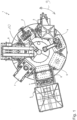
- a plate production system 1 with a turntable that can rotate about an axis 10 in the direction of arrow 9, is shown.
- This turntable has a plurality of stations 2, 3, 4, 5, 6, 7, 8, these individual stations also containing dosage forms in which the plate material is introduced and is treated differently in the various stations. For example, a pressing process takes place, a shaking process, the introduction of a facing material, the introduction of the backing concrete material, etc.
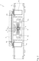
- In 2 is a cross-sectional view of in 1 shown turntable shown in cross section with the vibrating device according to the invention.
- this is a section 11 which shows a dosage form 12 with a vibrating device 16 arranged centrally underneath.
- the turntable or table 13 is connected by means of buffers and spring elements 20a and 20b and mold lifting cylinders 14a, 14b to a base frame, which also includes the dosage form 12, which can oscillate relative to the table 13.
- the vibrating device is for this 16 is firmly connected to the dosage form 12 via plates 17, 18, 19 and executes vibrations by means of a rotary movement, which vibrations are thus transmitted to the dosage form 12.
- the vibrating device is arranged inside the base frame or an enclosure 15 for better protection from external influences.
- the vibrating device 16 has two unbalanced masses or unbalanced elements 22, 23, which are described in more detail below.
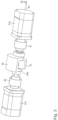
- the vibrating device 16 is shown in more detail in a perspective view. It can be seen from this representation that the vibrating device consists of the first and second unbalanced masses 22, 23, which are each connected at the end to a servomotor 21a, 21b. A coupling element 26, 27 is arranged between a motor and an associated unbalanced mass.
- All elements are arranged along an imaginary common central axis 24 .
- the angle of the two unbalanced masses 22, 23 can be changed relative to one another, as shown by the reference number 25, by changing their rotational position using the drive motors 21a, 21b.
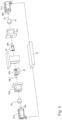
- In 4 is the vibrating device according to the invention 3 shown in the exploded view.
- the first unbalanced mass 22 is assigned the first servomotor 21b, which is firmly connected to the unbalanced mass 22 by means of an associated rotary shaft section 29a, which engages in a rotary shaft section 29b.
- the first rotary motor 21b can drive the unbalanced mass 22 in rotation.
- the clutch 26 and an associated clutch housing 26a can also be seen in this illustration. Both components are arranged between the servo motor and the first unbalanced mass 22 .
- the second servo motor 21a is connected to the second unbalanced mass 23 via the second rotary shaft section 28a, 28b.
- the clutch 27 and a clutch housing 27a are arranged in between.
- a vibrating housing for receiving the unbalanced masses is shown in the middle.
- a control device 30 is able to control the rotary motors 21a, 21b in their direction of rotation and in their speed, depending on or independently of one another.
- the first unbalanced mass 22 has a through-opening 22a, in which the second unbalanced mass 23 can also be accommodated in a specific rotational position.
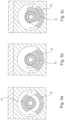
- Their effect is described below with reference to Figures 5a to 5c and Figures 6a to 6d in more detail.
- both unbalanced masses 22, 23 are arranged on the same side or one inside the other, as is possible when the second unbalanced mass 23 is positioned inside the first unbalanced mass 22 inside the cavity 22a. The consequence of this is that the two imbalances of the two unbalanced masses are added and thus a vibration with a maximum possible amplitude is generated.
Landscapes
- Engineering & Computer Science (AREA)
- Mechanical Engineering (AREA)
- Manufacturing & Machinery (AREA)
- Chemical & Material Sciences (AREA)
- Ceramic Engineering (AREA)
- Apparatuses For Generation Of Mechanical Vibrations (AREA)
- Jigging Conveyors (AREA)
Applications Claiming Priority (1)
| Application Number | Priority Date | Filing Date | Title |
|---|---|---|---|
| DE102019108840 | 2019-04-04 |
Publications (3)
| Publication Number | Publication Date |
|---|---|
| EP3718646A1 EP3718646A1 (de) | 2020-10-07 |
| EP3718646B1 true EP3718646B1 (de) | 2023-06-07 |
| EP3718646C0 EP3718646C0 (de) | 2023-06-07 |
Family
ID=70110152
Family Applications (1)
| Application Number | Title | Priority Date | Filing Date |
|---|---|---|---|
| EP20167207.8A Active EP3718646B1 (de) | 2019-04-04 | 2020-03-31 | Plattenproduktionsanlage mit rütteleinrichtung |
Country Status (2)
| Country | Link |
|---|---|
| EP (1) | EP3718646B1 (pl) |
| PL (1) | PL3718646T3 (pl) |
Families Citing this family (1)
| Publication number | Priority date | Publication date | Assignee | Title |
|---|---|---|---|---|
| CN116833808A (zh) * | 2023-07-28 | 2023-10-03 | 中国航发动力股份有限公司 | 一种数控电解机床的振动加工装置及方法 |
Citations (1)
| Publication number | Priority date | Publication date | Assignee | Title |
|---|---|---|---|---|
| DE10249551A1 (de) * | 2002-10-23 | 2003-07-03 | Karl Rekers Maschinen- Und Stahlbau Dipl.-Ing. | Schwingungserzeuger |
Family Cites Families (3)
| Publication number | Priority date | Publication date | Assignee | Title |
|---|---|---|---|---|
| ATE248691T1 (de) * | 1995-10-18 | 2003-09-15 | Cobber Engineering S R L | Vorrichtung zum herstellen von blöcken |
| DE19735268C2 (de) * | 1997-08-14 | 2002-04-18 | Karl Rekers Maschinen Und Stah | Schwingungserzeuger für insbesondere Rüttelstationen von Steinformmaschinen |
| DE102007012593B4 (de) * | 2007-03-13 | 2009-02-26 | Sr Schindler Steinbearbeitungsmaschinen-Anlagentechnik Gmbh | Vorrichtung zum Beschicken von Formen zum Herstellen von Betonplatten oder Betonsteinen |
-
2020
- 2020-03-31 PL PL20167207.8T patent/PL3718646T3/pl unknown
- 2020-03-31 EP EP20167207.8A patent/EP3718646B1/de active Active
Patent Citations (1)
| Publication number | Priority date | Publication date | Assignee | Title |
|---|---|---|---|---|
| DE10249551A1 (de) * | 2002-10-23 | 2003-07-03 | Karl Rekers Maschinen- Und Stahlbau Dipl.-Ing. | Schwingungserzeuger |
Non-Patent Citations (1)
| Title |
|---|
| ANLAGENBAU MASCHINEN-U: "REKERS REKERS", 14 March 2016 (2016-03-14), XP055972044, Retrieved from the Internet <URL:https://www.rekers.de/wp-content/uploads/Imagebroschuere_DEU-ENG.pdf> [retrieved on 20221017] * |
Also Published As
| Publication number | Publication date |
|---|---|
| EP3718646A1 (de) | 2020-10-07 |
| PL3718646T3 (pl) | 2023-11-06 |
| EP3718646C0 (de) | 2023-06-07 |
Similar Documents
| Publication | Publication Date | Title |
|---|---|---|
| DE112016000636T5 (de) | Schwingungsvorrichtung für Vibrationsverdichter | |
| WO2009106297A2 (de) | Betonsteinfertiger mit harmonischer vibration durch formerregung | |
| DE3634157C2 (de) | Rüttelvorrichtung mit zu verändernder Schwingkraft | |
| EP3372716A1 (de) | Nadelmaschine | |
| DE102004014750A1 (de) | Bodenverdichtungsvorrichtung | |
| EP3789126A1 (de) | Regelbare siebmaschine | |
| EP0943037B1 (de) | Bandage für walzen zur bodenverdichtung | |
| EP3718646A1 (de) | Plattenproduktionsanlage mit rütteleinrichtung | |
| DE19812986C1 (de) | Unwuchtrüttler für Steinformmaschinen | |
| DE69821247T2 (de) | Verfahren zum Verdichten von Formsand | |
| DE2001987A1 (de) | Bodenverdichtungsgeraet | |
| EP2242590B1 (de) | Unwuchterreger mit einer oder mehreren rotierbaren unwuchten | |
| EP1449965A2 (de) | Schwingungserregervorrichtung zur Bodenverdichtung | |
| DE102023200675B4 (de) | Schwingungserreger für ein bodenverdichtungsgerät, verfahren zum einstellen einer schwingungsamplitude eines schwingungserregers für ein bodenverdichtungsgerät sowie bodenverdichtungsgerät mit einem schwingungserreger | |
| EP3693090A1 (de) | Regelbare siebmaschine und verfahren zum betrieb einer regelbaren siebmaschine | |
| EP2724966A1 (de) | Verfahren zum Rütteln von gestapeltem, blattförmigem Gut mittels eines Rütteltisches sowie Vorrichtung zur Durchführung des Verfahrens | |
| DE1930787A1 (de) | Verfahren und Vorrichtung zum Kneten und/oder Mischen organischer oder anorganischer Stoffe | |
| WO2017076525A1 (de) | Schwingungserzeuger und verfahren zum einbringen eines rammgutes in einen boden | |
| DE19534203C1 (de) | Vibrationseinrichtung zum Verdichten und Glätten von plattenförmigen Betonfertigteilen | |
| DE718152C (de) | Knetmaschine fuer plastische Massen | |
| DE10003126C2 (de) | Walzapparat und Verfahren zum Justieren eines solchen | |
| DE4434221A1 (de) | Motorgetriebener Unwuchtvibrator | |
| EP2050873A2 (de) | Vibrationswalze | |
| DE3720179C2 (de) | Steinbearbeitungsvorrichtung | |
| DE2847165C2 (de) | Vibrations-Stoßmaschine |
Legal Events
| Date | Code | Title | Description |
|---|---|---|---|
| PUAI | Public reference made under article 153(3) epc to a published international application that has entered the european phase |
Free format text: ORIGINAL CODE: 0009012 |
|
| STAA | Information on the status of an ep patent application or granted ep patent |
Free format text: STATUS: THE APPLICATION HAS BEEN PUBLISHED |
|
| AK | Designated contracting states |
Kind code of ref document: A1 Designated state(s): AL AT BE BG CH CY CZ DE DK EE ES FI FR GB GR HR HU IE IS IT LI LT LU LV MC MK MT NL NO PL PT RO RS SE SI SK SM TR |
|
| AX | Request for extension of the european patent |
Extension state: BA ME |
|
| STAA | Information on the status of an ep patent application or granted ep patent |
Free format text: STATUS: REQUEST FOR EXAMINATION WAS MADE |
|
| 17P | Request for examination filed |
Effective date: 20210319 |
|
| RBV | Designated contracting states (corrected) |
Designated state(s): AL AT BE BG CH CY CZ DE DK EE ES FI FR GB GR HR HU IE IS IT LI LT LU LV MC MK MT NL NO PL PT RO RS SE SI SK SM TR |
|
| STAA | Information on the status of an ep patent application or granted ep patent |
Free format text: STATUS: EXAMINATION IS IN PROGRESS |
|
| 17Q | First examination report despatched |
Effective date: 20210831 |
|
| REG | Reference to a national code |
Ref country code: DE Ref legal event code: R079 Ref document number: 502020003468 Country of ref document: DE Free format text: PREVIOUS MAIN CLASS: B06B0001160000 Ipc: B28B0007000000 |
|
| RIC1 | Information provided on ipc code assigned before grant |
Ipc: B06B 1/16 20060101ALI20221109BHEP Ipc: B28B 1/087 20060101ALI20221109BHEP Ipc: B28B 5/08 20060101ALI20221109BHEP Ipc: B28B 7/00 20060101AFI20221109BHEP |
|
| GRAP | Despatch of communication of intention to grant a patent |
Free format text: ORIGINAL CODE: EPIDOSNIGR1 |
|
| STAA | Information on the status of an ep patent application or granted ep patent |
Free format text: STATUS: GRANT OF PATENT IS INTENDED |
|
| INTG | Intention to grant announced |
Effective date: 20230109 |
|
| GRAS | Grant fee paid |
Free format text: ORIGINAL CODE: EPIDOSNIGR3 |
|
| GRAA | (expected) grant |
Free format text: ORIGINAL CODE: 0009210 |
|
| STAA | Information on the status of an ep patent application or granted ep patent |
Free format text: STATUS: THE PATENT HAS BEEN GRANTED |
|
| AK | Designated contracting states |
Kind code of ref document: B1 Designated state(s): AL AT BE BG CH CY CZ DE DK EE ES FI FR GB GR HR HU IE IS IT LI LT LU LV MC MK MT NL NO PL PT RO RS SE SI SK SM TR |
|
| REG | Reference to a national code |
Ref country code: GB Ref legal event code: FG4D Free format text: NOT ENGLISH |
|
| REG | Reference to a national code |
Ref country code: CH Ref legal event code: EP Ref country code: AT Ref legal event code: REF Ref document number: 1573667 Country of ref document: AT Kind code of ref document: T Effective date: 20230615 |
|
| REG | Reference to a national code |
Ref country code: DE Ref legal event code: R096 Ref document number: 502020003468 Country of ref document: DE |
|
| U01 | Request for unitary effect filed |
Effective date: 20230615 |
|
| REG | Reference to a national code |
Ref country code: RO Ref legal event code: EPE |
|
| U07 | Unitary effect registered |
Designated state(s): AT BE BG DE DK EE FI FR IT LT LU LV MT NL PT SE SI Effective date: 20230707 |
|
| REG | Reference to a national code |
Ref country code: LT Ref legal event code: MG9D |
|
| PG25 | Lapsed in a contracting state [announced via postgrant information from national office to epo] |
Ref country code: NO Free format text: LAPSE BECAUSE OF FAILURE TO SUBMIT A TRANSLATION OF THE DESCRIPTION OR TO PAY THE FEE WITHIN THE PRESCRIBED TIME-LIMIT Effective date: 20230907 Ref country code: ES Free format text: LAPSE BECAUSE OF FAILURE TO SUBMIT A TRANSLATION OF THE DESCRIPTION OR TO PAY THE FEE WITHIN THE PRESCRIBED TIME-LIMIT Effective date: 20230607 |
|
| PG25 | Lapsed in a contracting state [announced via postgrant information from national office to epo] |
Ref country code: RS Free format text: LAPSE BECAUSE OF FAILURE TO SUBMIT A TRANSLATION OF THE DESCRIPTION OR TO PAY THE FEE WITHIN THE PRESCRIBED TIME-LIMIT Effective date: 20230607 Ref country code: HR Free format text: LAPSE BECAUSE OF FAILURE TO SUBMIT A TRANSLATION OF THE DESCRIPTION OR TO PAY THE FEE WITHIN THE PRESCRIBED TIME-LIMIT Effective date: 20230607 Ref country code: GR Free format text: LAPSE BECAUSE OF FAILURE TO SUBMIT A TRANSLATION OF THE DESCRIPTION OR TO PAY THE FEE WITHIN THE PRESCRIBED TIME-LIMIT Effective date: 20230908 |
|
| U1O | Appointed representative for the unitary patent procedure deleted after the registration of the unitary effect | ||
| U1N | Appointed representative for the unitary patent procedure changed after the registration of the unitary effect |
Representative=s name: RICHLY & RITSCHEL PATENTANWAELTE PARTG MBB; DE |
|
| PG25 | Lapsed in a contracting state [announced via postgrant information from national office to epo] |
Ref country code: SK Free format text: LAPSE BECAUSE OF FAILURE TO SUBMIT A TRANSLATION OF THE DESCRIPTION OR TO PAY THE FEE WITHIN THE PRESCRIBED TIME-LIMIT Effective date: 20230607 |
|
| PG25 | Lapsed in a contracting state [announced via postgrant information from national office to epo] |
Ref country code: IS Free format text: LAPSE BECAUSE OF FAILURE TO SUBMIT A TRANSLATION OF THE DESCRIPTION OR TO PAY THE FEE WITHIN THE PRESCRIBED TIME-LIMIT Effective date: 20231007 |
|
| PG25 | Lapsed in a contracting state [announced via postgrant information from national office to epo] |
Ref country code: SM Free format text: LAPSE BECAUSE OF FAILURE TO SUBMIT A TRANSLATION OF THE DESCRIPTION OR TO PAY THE FEE WITHIN THE PRESCRIBED TIME-LIMIT Effective date: 20230607 Ref country code: SK Free format text: LAPSE BECAUSE OF FAILURE TO SUBMIT A TRANSLATION OF THE DESCRIPTION OR TO PAY THE FEE WITHIN THE PRESCRIBED TIME-LIMIT Effective date: 20230607 Ref country code: IS Free format text: LAPSE BECAUSE OF FAILURE TO SUBMIT A TRANSLATION OF THE DESCRIPTION OR TO PAY THE FEE WITHIN THE PRESCRIBED TIME-LIMIT Effective date: 20231007 Ref country code: CZ Free format text: LAPSE BECAUSE OF FAILURE TO SUBMIT A TRANSLATION OF THE DESCRIPTION OR TO PAY THE FEE WITHIN THE PRESCRIBED TIME-LIMIT Effective date: 20230607 |
|
| REG | Reference to a national code |
Ref country code: DE Ref legal event code: R097 Ref document number: 502020003468 Country of ref document: DE |
|
| U20 | Renewal fee for the european patent with unitary effect paid |
Year of fee payment: 5 Effective date: 20240216 |
|
| PLBE | No opposition filed within time limit |
Free format text: ORIGINAL CODE: 0009261 |
|
| STAA | Information on the status of an ep patent application or granted ep patent |
Free format text: STATUS: NO OPPOSITION FILED WITHIN TIME LIMIT |
|
| 26N | No opposition filed |
Effective date: 20240308 |
|
| REG | Reference to a national code |
Ref country code: CH Ref legal event code: PL |
|
| PG25 | Lapsed in a contracting state [announced via postgrant information from national office to epo] |
Ref country code: MC Free format text: LAPSE BECAUSE OF FAILURE TO SUBMIT A TRANSLATION OF THE DESCRIPTION OR TO PAY THE FEE WITHIN THE PRESCRIBED TIME-LIMIT Effective date: 20230607 |
|
| PG25 | Lapsed in a contracting state [announced via postgrant information from national office to epo] |
Ref country code: MC Free format text: LAPSE BECAUSE OF FAILURE TO SUBMIT A TRANSLATION OF THE DESCRIPTION OR TO PAY THE FEE WITHIN THE PRESCRIBED TIME-LIMIT Effective date: 20230607 |
|
| PG25 | Lapsed in a contracting state [announced via postgrant information from national office to epo] |
Ref country code: IE Free format text: LAPSE BECAUSE OF NON-PAYMENT OF DUE FEES Effective date: 20240331 |
|
| PG25 | Lapsed in a contracting state [announced via postgrant information from national office to epo] |
Ref country code: IE Free format text: LAPSE BECAUSE OF NON-PAYMENT OF DUE FEES Effective date: 20240331 Ref country code: CH Free format text: LAPSE BECAUSE OF NON-PAYMENT OF DUE FEES Effective date: 20240331 |
|
| U20 | Renewal fee for the european patent with unitary effect paid |
Year of fee payment: 6 Effective date: 20250225 |
|
| PG25 | Lapsed in a contracting state [announced via postgrant information from national office to epo] |
Ref country code: CY Free format text: LAPSE BECAUSE OF FAILURE TO SUBMIT A TRANSLATION OF THE DESCRIPTION OR TO PAY THE FEE WITHIN THE PRESCRIBED TIME-LIMIT; INVALID AB INITIO Effective date: 20200331 |
|
| PG25 | Lapsed in a contracting state [announced via postgrant information from national office to epo] |
Ref country code: HU Free format text: LAPSE BECAUSE OF FAILURE TO SUBMIT A TRANSLATION OF THE DESCRIPTION OR TO PAY THE FEE WITHIN THE PRESCRIBED TIME-LIMIT; INVALID AB INITIO Effective date: 20200331 |
|
| PG25 | Lapsed in a contracting state [announced via postgrant information from national office to epo] |
Ref country code: TR Free format text: LAPSE BECAUSE OF FAILURE TO SUBMIT A TRANSLATION OF THE DESCRIPTION OR TO PAY THE FEE WITHIN THE PRESCRIBED TIME-LIMIT Effective date: 20230607 |
|
| U20 | Renewal fee for the european patent with unitary effect paid |
Year of fee payment: 7 Effective date: 20260227 |
|
| PGFP | Annual fee paid to national office [announced via postgrant information from national office to epo] |
Ref country code: GB Payment date: 20260324 Year of fee payment: 7 |
|
| PGFP | Annual fee paid to national office [announced via postgrant information from national office to epo] |
Ref country code: RO Payment date: 20260323 Year of fee payment: 7 |
|
| PGFP | Annual fee paid to national office [announced via postgrant information from national office to epo] |
Ref country code: PL Payment date: 20260320 Year of fee payment: 7 |