EP3718643B1 - Coating device for coating components - Google Patents
Coating device for coating components Download PDFInfo
- Publication number
- EP3718643B1 EP3718643B1 EP20170016.8A EP20170016A EP3718643B1 EP 3718643 B1 EP3718643 B1 EP 3718643B1 EP 20170016 A EP20170016 A EP 20170016A EP 3718643 B1 EP3718643 B1 EP 3718643B1
- Authority
- EP
- European Patent Office
- Prior art keywords
- printhead
- coating
- control
- robot
- coating agent
- Prior art date
- Legal status (The legal status is an assumption and is not a legal conclusion. Google has not performed a legal analysis and makes no representation as to the accuracy of the status listed.)
- Active
Links
- 239000011248 coating agent Substances 0.000 title claims description 131
- 238000000576 coating method Methods 0.000 title claims description 80
- 238000010422 painting Methods 0.000 claims description 25
- 239000003973 paint Substances 0.000 claims description 20
- 238000004519 manufacturing process Methods 0.000 claims description 6
- 238000004891 communication Methods 0.000 claims description 4
- 238000011156 evaluation Methods 0.000 claims description 4
- 239000007921 spray Substances 0.000 claims description 4
- 239000002904 solvent Substances 0.000 claims description 2
- 230000004888 barrier function Effects 0.000 claims 1
- 239000010445 mica Substances 0.000 claims 1
- 229910052618 mica group Inorganic materials 0.000 claims 1
- XLYOFNOQVPJJNP-UHFFFAOYSA-N water Substances O XLYOFNOQVPJJNP-UHFFFAOYSA-N 0.000 claims 1
- 239000004922 lacquer Substances 0.000 description 6
- 230000002123 temporal effect Effects 0.000 description 6
- 238000012546 transfer Methods 0.000 description 3
- 238000005034 decoration Methods 0.000 description 2
- 238000011161 development Methods 0.000 description 2
- 230000018109 developmental process Effects 0.000 description 2
- 239000003595 mist Substances 0.000 description 2
- 239000000243 solution Substances 0.000 description 2
- 239000000758 substrate Substances 0.000 description 2
- 239000000853 adhesive Substances 0.000 description 1
- 230000001070 adhesive effect Effects 0.000 description 1
- 238000005422 blasting Methods 0.000 description 1
- 239000000969 carrier Substances 0.000 description 1
- 230000001427 coherent effect Effects 0.000 description 1
- 238000004040 coloring Methods 0.000 description 1
- 238000012937 correction Methods 0.000 description 1
- 230000003111 delayed effect Effects 0.000 description 1
- 239000012628 flowing agent Substances 0.000 description 1
- 238000009434 installation Methods 0.000 description 1
- 239000011810 insulating material Substances 0.000 description 1
- 230000007257 malfunction Effects 0.000 description 1
- 239000000463 material Substances 0.000 description 1
- 238000005259 measurement Methods 0.000 description 1
- 230000003287 optical effect Effects 0.000 description 1
- 239000013615 primer Substances 0.000 description 1
- 239000002987 primer (paints) Substances 0.000 description 1
- 238000011002 quantification Methods 0.000 description 1
- 230000035484 reaction time Effects 0.000 description 1
- 239000000565 sealant Substances 0.000 description 1
- 230000001960 triggered effect Effects 0.000 description 1
- 238000012800 visualization Methods 0.000 description 1
- 239000004924 water-based lacquer Substances 0.000 description 1
Images
Classifications
-
- B—PERFORMING OPERATIONS; TRANSPORTING
- B05—SPRAYING OR ATOMISING IN GENERAL; APPLYING FLUENT MATERIALS TO SURFACES, IN GENERAL
- B05B—SPRAYING APPARATUS; ATOMISING APPARATUS; NOZZLES
- B05B12/00—Arrangements for controlling delivery; Arrangements for controlling the spray area
-
- B—PERFORMING OPERATIONS; TRANSPORTING
- B05—SPRAYING OR ATOMISING IN GENERAL; APPLYING FLUENT MATERIALS TO SURFACES, IN GENERAL
- B05B—SPRAYING APPARATUS; ATOMISING APPARATUS; NOZZLES
- B05B1/00—Nozzles, spray heads or other outlets, with or without auxiliary devices such as valves, heating means
- B05B1/14—Nozzles, spray heads or other outlets, with or without auxiliary devices such as valves, heating means with multiple outlet openings; with strainers in or outside the outlet opening
-
- B—PERFORMING OPERATIONS; TRANSPORTING
- B05—SPRAYING OR ATOMISING IN GENERAL; APPLYING FLUENT MATERIALS TO SURFACES, IN GENERAL
- B05B—SPRAYING APPARATUS; ATOMISING APPARATUS; NOZZLES
- B05B12/00—Arrangements for controlling delivery; Arrangements for controlling the spray area
- B05B12/08—Arrangements for controlling delivery; Arrangements for controlling the spray area responsive to condition of liquid or other fluent material to be discharged, of ambient medium or of target ; responsive to condition of spray devices or of supply means, e.g. pipes, pumps or their drive means
- B05B12/12—Arrangements for controlling delivery; Arrangements for controlling the spray area responsive to condition of liquid or other fluent material to be discharged, of ambient medium or of target ; responsive to condition of spray devices or of supply means, e.g. pipes, pumps or their drive means responsive to conditions of ambient medium or target, e.g. humidity, temperature position or movement of the target relative to the spray apparatus
-
- B—PERFORMING OPERATIONS; TRANSPORTING
- B05—SPRAYING OR ATOMISING IN GENERAL; APPLYING FLUENT MATERIALS TO SURFACES, IN GENERAL
- B05B—SPRAYING APPARATUS; ATOMISING APPARATUS; NOZZLES
- B05B13/00—Machines or plants for applying liquids or other fluent materials to surfaces of objects or other work by spraying, not covered by groups B05B1/00 - B05B11/00
- B05B13/02—Means for supporting work; Arrangement or mounting of spray heads; Adaptation or arrangement of means for feeding work
- B05B13/04—Means for supporting work; Arrangement or mounting of spray heads; Adaptation or arrangement of means for feeding work the spray heads being moved during spraying operation
- B05B13/0447—Installation or apparatus for applying liquid or other fluent material to conveyed separate articles
- B05B13/0452—Installation or apparatus for applying liquid or other fluent material to conveyed separate articles the conveyed articles being vehicle bodies
-
- B—PERFORMING OPERATIONS; TRANSPORTING
- B25—HAND TOOLS; PORTABLE POWER-DRIVEN TOOLS; MANIPULATORS
- B25J—MANIPULATORS; CHAMBERS PROVIDED WITH MANIPULATION DEVICES
- B25J11/00—Manipulators not otherwise provided for
- B25J11/0075—Manipulators for painting or coating
-
- B—PERFORMING OPERATIONS; TRANSPORTING
- B05—SPRAYING OR ATOMISING IN GENERAL; APPLYING FLUENT MATERIALS TO SURFACES, IN GENERAL
- B05B—SPRAYING APPARATUS; ATOMISING APPARATUS; NOZZLES
- B05B12/00—Arrangements for controlling delivery; Arrangements for controlling the spray area
- B05B12/14—Arrangements for controlling delivery; Arrangements for controlling the spray area for supplying a selected one of a plurality of liquids or other fluent materials or several in selected proportions to a spray apparatus, e.g. to a single spray outlet
- B05B12/149—Arrangements for controlling delivery; Arrangements for controlling the spray area for supplying a selected one of a plurality of liquids or other fluent materials or several in selected proportions to a spray apparatus, e.g. to a single spray outlet characterised by colour change manifolds or valves therefor
-
- B—PERFORMING OPERATIONS; TRANSPORTING
- B05—SPRAYING OR ATOMISING IN GENERAL; APPLYING FLUENT MATERIALS TO SURFACES, IN GENERAL
- B05B—SPRAYING APPARATUS; ATOMISING APPARATUS; NOZZLES
- B05B13/00—Machines or plants for applying liquids or other fluent materials to surfaces of objects or other work by spraying, not covered by groups B05B1/00 - B05B11/00
- B05B13/02—Means for supporting work; Arrangement or mounting of spray heads; Adaptation or arrangement of means for feeding work
- B05B13/04—Means for supporting work; Arrangement or mounting of spray heads; Adaptation or arrangement of means for feeding work the spray heads being moved during spraying operation
- B05B13/0431—Means for supporting work; Arrangement or mounting of spray heads; Adaptation or arrangement of means for feeding work the spray heads being moved during spraying operation with spray heads moved by robots or articulated arms, e.g. for applying liquid or other fluent material to 3D-surfaces
Definitions
- the invention relates to a coating device for coating components with a coating agent, in particular for painting motor vehicle body components.
- rotary atomizers are usually used as application devices, but these have the disadvantage of a limited application efficiency, i.e. only part of the applied paint is deposited on the components to be coated, while the rest of the applied paint has to be disposed of as a so-called overspray.
- print heads as application devices, as they are, for example DE 10 2013 002 412 A1 , US 9,108,424 B2 and DE 10 2010 019 612 A1 are known.
- print heads do not emit a spray mist of the paint to be applied, but a spatially narrowly limited paint jet that is almost completely reflected on the component to be painted, so that almost no overspray occurs.
- the paint jet When coating a limited area (e.g. a decoration) on a component surface by means of such a print head, however, the paint jet must be controlled very precisely in terms of time and space so that the boundaries of the surface to be coated are adhered to without being exceeded during painting Falling below the limit of to coating surface comes.
- the applicators In order to be able to produce cost-effectively and competitively or to achieve high area performance, the applicators must be moved quickly with the robot, for example with a pulling speed in the range of 0.5 m / s to 0.75 m / s.
- the combination of the exact switch-on and switch-off positions of the applicators or their individual valves as well as the high painting speed results in the need for very short reaction times or control pulses (e.g.
- a coating system in which a coating robot moves a print head over the components to be coated.
- the coating robot is controlled by a robot controller.
- a separate control unit is provided which controls a metering unit and sets the desired paint flow.
- a separate printhead control is not known from this publication.
- the invention is therefore based on the object of solving this problem.
- the invention encompasses the general technical teaching not to activate the printhead valves in the printhead by the robot controller which controls the coating robot. Instead, the invention rather provides a separate print head control which controls the print head valves in the print head and operates sufficiently quickly to achieve the required temporal and spatial accuracy when controlling the emitted lacquer jets. There should be communication with the robot controller so that the print head controller can be instructed accordingly.
- the coating device according to the invention is used to coat components such as motor vehicle body components.
- components such as motor vehicle body components.
- the invention is not restricted to motor vehicle body components. Rather, the components to be coated can also be other components.
- the coating device is preferably designed for painting components with a lacquer
- the coating agent to be applied is preferably a lacquer, such as a solvent-based lacquer, a water-based lacquer, a coloring basecoat or a clear lacquer to name just a few examples.
- the type of coating agent to be applied the invention is not limited to paints, but in principle also includes other types of coating materials can be implemented, such as adhesives, insulating materials, sealants, primers, etc., to name just a few examples.
- the coating device has, as an application device, a print head with several nozzles in order to emit a jet of coating agent onto the component to be coated, the release of the coating agent through the nozzle being controlled by means of a printhead valve.
- pressure head used in the context of the invention is initially to be understood in general terms and serves only to differentiate from conventional atomizers (eg rotary atomizers) which do not emit a spatially narrow jet of coating agent, but rather a spray of the coating agent.
- the printhead is a printhead such as that shown in, for example DE 10 2013 002 412 A1 , US 9,108,424 B2 and DE 10 2010 019 612 A1 is described.
- the coating device comprises a multi-axis coating robot which guides the pressure head over the surface of the component to be coated.
- the coating robot preferably has serial robot kinematics with at least six or seven movable robot axes and a robot hand axis in order to guide the print head in a highly movable manner over the component surface.
- Such coating robots are known per se from the prior art and therefore do not need to be described in more detail.
- the coating device according to the invention has a robot controller which controls the coating robot.
- the coating device according to the invention is now distinguished from the prior art - as already briefly mentioned above - by a separate print head control, which is separate from the robot control and controls the print head valves, the print head control working sufficiently quickly to achieve the required temporal and spatial accuracy to achieve in the control of the coating agent release.
- the robot controller usually controls the coating robot with a certain first cycle time, this first cycle time being too long to achieve the desired temporal and spatial accuracy of the coating agent delivery when controlling the printhead valves.
- the printhead control according to the invention preferably works clocked with a certain second cycle time, this second cycle time of the printhead control being shorter than the first cycle time of the robot control, so that the printhead control can achieve the necessary temporal and spatial accuracy of the control of the coating agent delivery when controlling the printhead valves.
- the position of the print head is only known quantized in units of the robot control clock rate.
- this quantification of the position is 3 mm.
- the second cycle time of the printhead position is therefore preferably at most 100 ms, 50 ms, 20 ms, 10 ms, 5 ms, 1 ms or even at most 100 ⁇ s.
- the print head control is preferably connected on the input side to the robot control and receives the current spatial position, the current spatial position and / or the current speed and / or the current spatial orientation of the print head and / or the coating object from the robot control at the clock rate of the robot control Input information so that the printhead control can take this information into account when controlling the printhead valves.
- the printhead control interpolates or extrapolates (e.g. linear, with splines, cubic) these positions to their own time steps, so that it receives a higher position resolution.
- the switch-on and switch-off point of the coating agent flow or coating agent drop can be set precisely.
- the print head control can, for example, also be integrated into the robot control as an independently operating module.
- the coating device according to the invention preferably contains a color changer which selects one of several coating agents and forwards the selected coating agent to the print head.
- the coating device according to the invention preferably contains a metering pump which meters the coating agent to be applied and conveys it to the print head.
- the printhead control not only controls the printhead valves of the printhead, but preferably also the color changer and / or the metering pump.
- the printhead control can switch the coating agent jet applied by the printhead on and off in a highly dynamic and precisely controlled manner in order to be able to achieve coating patterns with a very precise spatial resolution on the component surface. This is important, for example, if a surface to be coated has a sharp edge that must be precisely adhered to during the coating.
- the pressure head control therefore preferably works so quickly and precisely that the coating agent jet on the component surface achieves an exact spatial resolution of less than ⁇ 2mm, ⁇ 1mm, ⁇ 0.5mm or even less than ⁇ 0.1mm.
- a measuring device which measures the spatial position and / or orientation of the component to be coated and transmits the determined position and / or orientation to the printhead control so that the printhead control can take this into account when controlling the printhead valves.
- the measuring device can either be connected directly to the print head control or indirectly via the robot control to the print head control.
- the only decisive factor in the context of the invention is that the determined position or orientation of the component to be coated can be taken into account when controlling the printhead valves.
- the measuring device has a camera that records an image of the component to be coated, this image being evaluated by an image evaluation unit which uses it to determine the spatial position or orientation of the component to be coated.
- an image evaluation unit which uses it to determine the spatial position or orientation of the component to be coated.
- the measuring device can determine the spatial position and / or orientation of the component to be coated with a very high degree of accuracy and a correspondingly low position tolerance, the position tolerance preferably being less than ⁇ 2mm, ⁇ 1mm, ⁇ 0.5mm, ⁇ 0.25mm or even smaller than ⁇ 0.1mm.
- the coating device in addition to the print head control and the robot control, has an additional dosing control in order to control the already mentioned dosing device (e.g. dosing cylinder, dosing pump, etc.), which doses the coating agent and conveys it to the print head.
- the already mentioned dosing device e.g. dosing cylinder, dosing pump, etc.
- the dosing control is connected to the printhead control in order to synchronize the control of the dosing pump with the control of the printhead valves of the printhead. If For example, if numerous printhead valves are suddenly opened, then the coating agent consumption suddenly increases, so that the metering pump should then also be operated at a higher output.
- the dosing control is preferably also connected to the robot control in order to synchronize the control of the dosing pump with the control of the coating robot. If the robot controller controls the coating robot, for example, in such a way that the print head is moved over the component surface at a high drawing speed, a large amount of coating usually has to be conveyed by the metering pump, so that synchronization of the robot controller on the one hand and the metering controller on the other hand is advantageous .
- the invention enables highly dynamic and precise control of the printhead valves by providing a separate printhead control which works sufficiently quickly. However, this only makes sense if the printhead valves themselves work sufficiently quickly.
- the printhead valves therefore preferably have a very short switching time of at most 100 ms, 50 ms, 20 ms, 5 ms, 1 ms or even at most 100 ⁇ s. A very good reproducibility or repeat accuracy of the switching times of all valves is even more important in order to correct them individually if necessary.
- the coating device according to the invention can have a first data interface in order to communicate with production planning, which, however, is known per se from the prior art and therefore does not need to be described in more detail.
- the coating device according to the invention can have a second data interface in order to receive a control file, wherein the control file can, for example, specify a graphic that is to be applied to the component surface by the coating device.
- This second data interface can, for example, by means of a USB-Stick reader (USB: U niversal S erial B us) or by means of a memory card reader can be realized, just to name a few examples.
- painting statistics are kept.
- a paint requirement quantity calculation can also take place.
- communication with a graphic visualization computer there is the possibility of communication with a safety controller.
- a higher-level control system can give approval for painting, which also checks whether a supply air system is in operation and there are no safety-relevant malfunctions.
- the print head control can release the paint if it determines that the color printing is OK, the metering pump is working, the coating robot is in its starting position, the optical measurement is ready, the vehicle has been measured and a position correction has been made.
- the print head preferably emits a narrowly limited jet of coating agent in contrast to a spray mist, as is the case with conventional atomizers (eg rotary atomizers).
- the print head emits a jet of droplets which consists of numerous droplets which are separated from one another in the longitudinal direction of the droplet jet, in contrast to a coating agent jet which is contiguous in the longitudinal direction of the jet.
- the print head emits a jet of coating agent that is contiguous in the longitudinal direction of the jet, in contrast to a jet of droplets.
- the print head can alternately emit a jet of droplets and a continuous jet of coating agent.
- the print head can alternately emit a jet of droplets and a continuous jet of coating agent.
- some of the nozzles of the printhead emit a jet of droplets, while at the same time another part of the nozzles of the same printhead emits a coating agent jet that is contiguous in the longitudinal direction of the jet.
- the coating agent pressure is preferably controlled with a relatively small fluctuation range of a maximum of ⁇ 500 mbar, ⁇ 200 mbar, ⁇ 100 mbar or even ⁇ 50 mbar.
- the advantage of using a print head as an application device is the high transfer efficiency, which is preferably greater than 80%, 90%, 95% or even 99%, so that the print head works essentially without overspray.
- the print head preferably has a sufficiently high surface coating performance to be able to efficiently paint motor vehicle body components. Therefore, the print head preferably has a surface coating performance of at least 0.5 m 2 / min, 1m 2 / min, 2m 2 / min or even 3m 2 / min.
- the volume flow of the applied coating agent and thus the exit speed of the coating agent is preferably set in such a way that the coating agent does not bounce off the component after it hits the component or wet-on-wet when applying paint -wet ”) does not penetrate the lower layer of lacquer or push it aside or displace it.
- the exit speed of the coating agent from the print head can therefore be, for example, in the range from 5 m / s to 30 m / s, with any number of intermediate intervals being possible.
- the application distance i.e. the distance between the nozzle and the component surface
- the application distance is preferably in the range from 4mm to 200mm.
- each printhead valve preferably has an electrically controllable actuator, for example a magnetic actuator or a piezo actuator, in order to enable the desired rapid response.
- an electrically controllable actuator for example a magnetic actuator or a piezo actuator
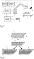
- Figure 1 shows a greatly simplified schematic representation of a paint shop according to the invention for painting motor vehicle body components 1 with a paint.
- the motor vehicle body components 1 are here conveyed in a conventional manner by a conveyor along a painting line through the painting installation, which is known per se from the prior art and is therefore not shown for the sake of simplicity.
- the painting takes place here by a multi-axis painting robot 2 with serial robot kinematics and several robot arms and a highly movable robot hand axis that guides a print head 3 as an application device.
- the print head 3 then emits jets of coating agent 4 onto the surface of the motor vehicle body component 1, as is shown schematically.
- the painting robot 2 is arranged in a painting booth which typically contains several such painting robots 2 on both sides of the painting line, only a single painting robot 2 being shown for the sake of simplicity.
- the painting robot 2 can be controlled in a conventional manner by a robot controller 5, the robot controller 5 operating clocked with a certain cycle time and therefore only enables positioning with a limited spatial resolution in accordance with the cycle time.
- the spatial resolution that can be achieved in this way is not sufficiently precise to allow the print head 3 to paint precisely on the component surface.
- the coating device according to the invention therefore additionally has a camera 6 which records an image of the motor vehicle body component 1 and the painting robot 2 in order to enable precise relative positioning of the painting robot 2 with the print head 3 relative to the motor vehicle body component 1.
- the image recorded by the camera 6 is then evaluated by an image evaluation unit, the image evaluation unit not being shown here for the sake of simplicity.
- the coating device according to the invention therefore preferably has a separate printhead control 7, which controls the printhead valves located in the printhead 3 and not shown for the sake of simplicity in a highly precise and highly dynamic manner in terms of time.
- the printhead controller 7 is connected on the input side to the robot controller 5 and receives the current position and orientation of the motor vehicle body component 1 relative to the printhead 3 from the robot controller 5 in order to be able to take this input information into account when controlling the printhead valves in the printhead 3.
- the coating device has, inter alia, a color changer and a metering pump, which are not shown for the sake of simplicity.
- the color changer and the metering pump are controlled by an additional metering controller 8, which is connected to the pressure head controller 7 and the robot controller 5.
- the production planning 9 in turn has a data interface, for example in the form of a USB stick reader, so that a control file can be read in by means of a USB stick 10 that defines a graphic (e.g. a decoration) that is applied to the component surface of the motor vehicle body component shall be.
- a data interface for example in the form of a USB stick reader, so that a control file can be read in by means of a USB stick 10 that defines a graphic (e.g. a decoration) that is applied to the component surface of the motor vehicle body component shall be.
- the graphic is then assigned to the serial number of the body in the production software.
- the data transfer to the robot control then takes place via an interface of the production software and the identification usually via reading points and data carriers on the body. Not only the serial number can be stored on the data carrier, but also other data, possibly the graphic data.
- the robot controller 5, the print head controller 7 and the dosage controller 8 are preferably designed as separate hardware components and are separate from one another.
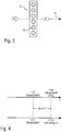
- FIG. 2 shows Figure 2 in the upper area a limited surface 12 to be coated, which is swept over by the print head 3 along the programmed movement path 11.
- the print head 3 passes the boundary of the surface 12 to be coated, which is on the left in the drawing, so that the coating should also begin at this point in time.
- the print head 3 passes the opposite border of the surface 12 to be coated, so that the print head 3 should stop coating again precisely at this point in time.
- Figure 2 shows the actual opening times 13 of the printhead valves of the printhead 3 in the middle area.
- the printhead 3 has six nozzles in a row. In practice, however, the printhead 3 has a larger number of nozzles and a larger number of rows of nozzles, which, however, is irrelevant for the principle of the invention.
- the actual opening times 13 of the printhead valves of the printhead 3 are spatially exactly within the surface 12 to be coated, as in FIG Figure 2 is shown at the bottom right.
- the printhead valves in printhead 3 would open with a time offset ⁇ t when triggered by the relatively sluggish robot controller 5 when the printhead 3 passes the border of the surface 12 to be coated along the programmed movement path 11.
- the spatial offset ⁇ s and thus the achievable spatial resolution during painting depends on the pulling speed v of the print head 3 along the programmed movement path 11 and the time offset ⁇ t.
- the offset can be compensated for by a lead time, for example.
- One problem, however, is the timing of the controller, which generates a repetition error ("jitter"). It is therefore important that the control of the printhead valves in the printhead 3 takes place in a highly dynamic manner in terms of time and very precisely in terms of time.
- Figure 3 shows a simplified schematic representation of the print head 3 with six nozzles 14, which are arranged in a single row of nozzles.
- the printhead 3 typically has a larger number of nozzles 14 per row of nozzles and also a larger number of rows of nozzles, which, however, is not relevant to the invention.
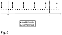
- Figure 5 shows a schematic representation to clarify the interpolation of the positions in the print head control from the positions in the robot control.
- the drawing in the upper area shows the positions stored in the robot controller along a time axis, the positions being shown as time stamps ⁇ and ⁇ . Below that, the drawing shows the positions stored in the print head control along the time axis.
- the filled in time stamps ⁇ each illustrate a point in time at which the coating agent is applied, while the unfilled time stamps ⁇ each symbolize a point in time at which no coating agent is applied.
- the printhead control enables this finer spatial resolution of the positions in that the printhead control interpolates finer positions from the relatively coarse positions of the robot control.
Landscapes
- Engineering & Computer Science (AREA)
- Robotics (AREA)
- Mechanical Engineering (AREA)
- Spray Control Apparatus (AREA)
- Coating Apparatus (AREA)
- Application Of Or Painting With Fluid Materials (AREA)
Description
Die Erfindung betrifft eine Beschichtungseinrichtung zur Beschichtung von Bauteilen mit einem Beschichtungsmittel, insbesondere zur Lackierung von Kraftfahrzeugkarosseriebauteilen.The invention relates to a coating device for coating components with a coating agent, in particular for painting motor vehicle body components.
Zur Serienlackierung von Kraftfahrzeugkarosseriebauteilen werden als Applikationsgerät üblicherweise Rotationszerstäuber eingesetzt, die jedoch den Nachteil eines beschränkten Auftragswirkungsgrades haben, d.h. nur ein Teil des applizierten Lacks lagert sich auf den zu beschichtenden Bauteilen ab, während der Rest des applizierten Lacks als sogenannter Overspray entsorgt werden muss.For the serial painting of motor vehicle body components, rotary atomizers are usually used as application devices, but these have the disadvantage of a limited application efficiency, i.e. only part of the applied paint is deposited on the components to be coated, while the rest of the applied paint has to be disposed of as a so-called overspray.
Eine neuere Entwicklungslinie sieht dagegen als Applikationsgerät sogenannte Druckköpfe vor, wie sie beispielsweise aus
Bei der Beschichtung einer begrenzten Fläche (z.B. ein Dekor) auf einer Bauteiloberfläche mittels eines solchen Druckkopfs muss der Lackstrahl jedoch zeitlich und räumlich sehr genau gesteuert werden, damit die Grenzen der zu beschichtenden Fläche eingehalten werden, ohne dass es beim Lackieren zu einem Überschreiten oder einem Unterschreiten der Grenze der zu beschichtenden Fläche kommt. Um kostengünstig und wettbewerbsfähig produzieren zu können bzw. um hohe Flächenleistungen zu erzielen, müssen die Applikatoren mit dem Roboter schnell bewegt werden, z.B. mit einer Ziehgeschwindigkeit im Bereich von 0,5m/s bis 0,75m/s. Die Kombination aus exakten Ein- und Ausschaltpositionen der Applikatoren oder deren einzelnen Ventile sowie der hohen Lackiergeschwindigkeit ergibt die Notwendigkeit von sehr kurzen Reaktionszeiten bzw. Steuerungsimpulsen (z.B. 1ms, 500µs, 100µs, 10µs), die üblicherweise mit den Robotersteuerungen nicht möglich sind. Hierzu müssen Druckkopfventile in dem Druckkopf zeitlich sehr genau ein- bzw. ausgeschaltet werden, um den Lackierstrahl entsprechend einzuschalten bzw. auszuschalten. Dies ist jedoch mit den üblichen Robotersteuerungen nicht möglich, da diese Robotersteuerungen mit einer bestimmten Zykluszeit getaktet arbeiten, wobei die Zykluszeit der Robotersteuerung zu lang ist, um die erforderliche zeitliche Genauigkeit bei der Steuerung der Druckkopfventile zu erreichen.When coating a limited area (e.g. a decoration) on a component surface by means of such a print head, however, the paint jet must be controlled very precisely in terms of time and space so that the boundaries of the surface to be coated are adhered to without being exceeded during painting Falling below the limit of to coating surface comes. In order to be able to produce cost-effectively and competitively or to achieve high area performance, the applicators must be moved quickly with the robot, for example with a pulling speed in the range of 0.5 m / s to 0.75 m / s. The combination of the exact switch-on and switch-off positions of the applicators or their individual valves as well as the high painting speed results in the need for very short reaction times or control pulses (e.g. 1ms, 500µs, 100µs, 10µs), which are usually not possible with the robot controls. For this purpose, printhead valves in the printhead have to be switched on and off very precisely in terms of time in order to switch the painting jet on or off accordingly. However, this is not possible with the usual robot controls, since these robot controls work clocked with a certain cycle time, the cycle time of the robot control being too long to achieve the required temporal accuracy when controlling the printhead valves.
Aus
Ferner ist zum allgemeinen technischen Hintergrund der Erfindung hinzuweisen auf
Der Erfindung liegt deshalb die Aufgabe zugrunde, dieses Problem zu lösen.The invention is therefore based on the object of solving this problem.
Diese Aufgabe wird durch eine erfindungsgemäße Beschichtungseinrichtung gemäß dem Hauptanspruch gelöst.This object is achieved by a coating device according to the invention according to the main claim.
Die Erfindung umfasst die allgemeine technische Lehre, die Druckkopfventile in dem Druckkopf nicht durch die Roboter-steuerung anzusteuern, die den Beschichtungsroboter steuert. Stattdessen sieht die Erfindung vielmehr eine separate Drucckopfsteuerung vor, welche die Druckkopfventile in dem Drucckopf steuert und hinreichend schnell arbeitet, um die erforderliche zeitliche und räumliche Genauigkeit bei der Steuerung der abgegebenen Lackstrahlen zu erreichen. Eine Kommunikation mit der Robotersteuerung sollte vorhanden sein, um die Druckkopfsteuerung entsprechend zu beauftragen.The invention encompasses the general technical teaching not to activate the printhead valves in the printhead by the robot controller which controls the coating robot. Instead, the invention rather provides a separate print head control which controls the print head valves in the print head and operates sufficiently quickly to achieve the required temporal and spatial accuracy when controlling the emitted lacquer jets. There should be communication with the robot controller so that the print head controller can be instructed accordingly.
Die erfindungsgemäße Beschichtungseinrichtung dient zur Beschichtung von Bauteilen, wie beispielsweise Kraftfahrzeugkarosseriebauteilen. Die Erfindung ist jedoch hinsichtlich des Typs der zu beschichtenden Bauteile nicht auf Kraftfahrzeugkarosseriebauteile beschränkt. Vielmehr kann es sich bei den zu beschichtenden Bauteilen auch um andere Bauteile handeln.The coating device according to the invention is used to coat components such as motor vehicle body components. However, with regard to the type of components to be coated, the invention is not restricted to motor vehicle body components. Rather, the components to be coated can also be other components.
Weiterhin ist zu erwähnen, dass die Beschichtungseinrichtung vorzugsweise zur Lackierung von Bauteilen mit einem Lack ausgelegt ist, d.h. bei dem zu applizierenden Beschichtungsmittel handelt es sich vorzugsweise um einen Lack, wie beispielsweise einen lösemittelbasierten Lack, einen Wasserlack, einen farbgebenden Basislack oder einen Klarlack, um nur einige Beispiele zu nennen. Die Erfindung ist jedoch hinsichtlich des Typs des zu applizierenden Beschichtungsmittels nicht auf Lacke beschränkt, sondern grundsätzlich auch mit anderen Typen von Beschichtungsmitteln realisierbar, wie beispielsweise mit Klebern, Dämmstoffen, Dichtstoffen, Primern, etc., um nur einige Beispiele zu nennen.It should also be mentioned that the coating device is preferably designed for painting components with a lacquer, ie the coating agent to be applied is preferably a lacquer, such as a solvent-based lacquer, a water-based lacquer, a coloring basecoat or a clear lacquer to name just a few examples. However, with regard to the type of coating agent to be applied, the invention is not limited to paints, but in principle also includes other types of coating materials can be implemented, such as adhesives, insulating materials, sealants, primers, etc., to name just a few examples.
Die erfindungsgemäße Beschichtungseinrichtung weist als Applikationsgerät einen Druckkopf mit mehreren Düsen auf, um einen Beschichtungsmittelstrahl auf das zu beschichtende Bauteil abzugeben, wobei die Beschichtungsmittelabgabe durch die Düse mittels eines Druckkopfventils gesteuert wird.The coating device according to the invention has, as an application device, a print head with several nozzles in order to emit a jet of coating agent onto the component to be coated, the release of the coating agent through the nozzle being controlled by means of a printhead valve.
Der im Rahmen der Erfindung verwendete Begriff eines Drucckopfs ist zunächst allgemein zu verstehen und dient lediglich zur Abgrenzung von herkömmlichen Zerstäubern (z.B. Rotationszerstäuber), die keinen räumlich eng begrenzten Beschichtungsmittelstrahl abgeben, sondern einen Sprühnebel des Beschichtungsmittels. Vorzugsweise handelt es sich bei dem Druckkopf jedoch um einen Druckkopf, wie er beispielsweise in
Weiterhin umfasst die erfindungsgemäße Beschichtungseinrichtung einen mehrachsigen Beschichtungsroboter, der den Drucckopf über die Oberfläche des zu beschichtenden Bauteils führt. Der Beschichtungsroboter weist vorzugsweise eine serielle Roboterkinematik mit mindestens sechs oder sieben beweglichen Roboterachsen und einer Roboterhandachse auf, um den Druckkopf hochbeweglich über die Bauteiloberfläche zu führen. Derartige Beschichtungsroboter sind an sich aus dem Stand der Technik bekannt und müssen deshalb nicht näher beschrieben werden.Furthermore, the coating device according to the invention comprises a multi-axis coating robot which guides the pressure head over the surface of the component to be coated. The coating robot preferably has serial robot kinematics with at least six or seven movable robot axes and a robot hand axis in order to guide the print head in a highly movable manner over the component surface. Such coating robots are known per se from the prior art and therefore do not need to be described in more detail.
Darüber hinaus weist die erfindungsgemäße Beschichtungseinrichtung im Einklang mit dem Stand der Technik eine Roboter-steuerung auf, die den Beschichtungsroboter ansteuert.In addition, in accordance with the prior art, the coating device according to the invention has a robot controller which controls the coating robot.
Die erfindungsgemäße Beschichtungseinrichtung zeichnet sich nun gegenüber dem Stand der Technik - wie bereits vorstehend kurz erwähnt wurde - durch eine separate Druckkopfsteuerung aus, die von der Robotersteuerung getrennt ist und die Druckkopfventile ansteuert, wobei die Drucckopfsteuerung hinreichend schnell arbeitet, um die erforderliche zeitliche und räumliche Genauigkeit bei der Steuerung der Beschichtungsmittelabgabe zu erreichen.The coating device according to the invention is now distinguished from the prior art - as already briefly mentioned above - by a separate print head control, which is separate from the robot control and controls the print head valves, the print head control working sufficiently quickly to achieve the required temporal and spatial accuracy to achieve in the control of the coating agent release.
Es wurde bereits eingangs kurz erwähnt, dass die Robotersteuerung den Beschichtungsroboter in der Regel mit einer bestimmten ersten Zykluszeit getaktet ansteuert, wobei diese erste Zykluszeit zu lang ist, um bei der Ansteuerung der Druckkopfventile die gewünschte zeitliche und räumliche Genauigkeit der Beschichtungsmittelabgabe zu erreichen. Die erfindungsgemäße Druckkopfsteuerung arbeitet vorzugsweise getaktet mit einer bestimmten zweiten Zykluszeit, wobei diese zweite Zykluszeit der Druckkopfsteuerung kürzer ist als die erste Zykluszeit der Robotersteuerung, damit die Drucckopfsteuerung bei der Ansteuerung der Druckkopfventile die erforderliche zeitliche und räumliche Genauigkeit der Steuerung der Beschichtungsmittelabgabe erreichen kann.It was already mentioned briefly at the beginning that the robot controller usually controls the coating robot with a certain first cycle time, this first cycle time being too long to achieve the desired temporal and spatial accuracy of the coating agent delivery when controlling the printhead valves. The printhead control according to the invention preferably works clocked with a certain second cycle time, this second cycle time of the printhead control being shorter than the first cycle time of the robot control, so that the printhead control can achieve the necessary temporal and spatial accuracy of the control of the coating agent delivery when controlling the printhead valves.
Bei einer Verfahrgeschwindigkeit des Druckkopfes ist die Position des Druckkopfes nur quantisiert in Einheiten der Robotersteuerungstaktrate bekannt. Bei einer Verfahrgeschwindigkeit v=750 mm/s und einer Robotersteuerungstaktrate von 4ms beträgt diese Positionsquantelung 3 mm. Für eine genauere Positionierung (< 1mm, < 0.1 mm) des An- bzw. Abschaltpunkts des Beschichtungsmittels auf dem Substrat, z.B. exakt an der Kante des Substrats, reicht dies nicht aus.With a travel speed of the print head, the position of the print head is only known quantized in units of the robot control clock rate. With a travel speed of v = 750 mm / s and a robot control clock rate of 4 ms, this quantification of the position is 3 mm. For a more precise positioning (<1mm, <0.1 mm) of the switch-on or switch-off point of the coating agent on the substrate, for example exactly at the edge of the substrate, this is not sufficient.
Die zweite Zykluszeit der Druckkopfstellung beträgt deshalb vorzugsweise höchstens 100ms, 50ms, 20ms, 10ms, 5ms, 1ms oder sogar höchstens 100µs.The second cycle time of the printhead position is therefore preferably at most 100 ms, 50 ms, 20 ms, 10 ms, 5 ms, 1 ms or even at most 100 μs.
Die Druckkopfsteuerung ist vorzugsweise eingangsseitig mit der Robotersteuerung verbunden und erhält von der Roboter-steuerung mit der Taktrate der Robotersteuerung die aktuelle räumliche Position die aktuelle räumliche Position und/oder die aktuelle Geschwindigkeit und/oder die aktuelle räumliche Ausrichtung des Druckkopfs und/oder des Beschichtungsobjekts als Eingangsinformation, damit die Druckkopfsteuerung diese Information bei der Steuerung der Druckkopfventile berücksichtigen kann.The print head control is preferably connected on the input side to the robot control and receives the current spatial position, the current spatial position and / or the current speed and / or the current spatial orientation of the print head and / or the coating object from the robot control at the clock rate of the robot control Input information so that the printhead control can take this information into account when controlling the printhead valves.
Die Druckkopfsteuerung interpoliert bzw. extrapoliert (z.B. linear, mit Splines, kubisch) diese Positionen auf ihre eigenen Zeitschritte, sodass sie eine höhere Positionsauflösung erhält. Dadurch kann der An- bzw. Abschaltpunkt des Beschichtungsmittelstroms bzw. Beschichtungsmitteltropfens genau gesetzt werden.The printhead control interpolates or extrapolates (e.g. linear, with splines, cubic) these positions to their own time steps, so that it receives a higher position resolution. As a result, the switch-on and switch-off point of the coating agent flow or coating agent drop can be set precisely.
Die Druckkopfsteuerung kann beispielsweise auch als unabhängig arbeitendes Modul in die Roboter-Steuerung integriert sein.The print head control can, for example, also be integrated into the robot control as an independently operating module.
Weiterhin ist zu erwähnen, dass die erfindungsgemäße Beschichtungseinrichtung vorzugsweise einen Farbwechsler enthält, der eines von mehreren Beschichtungsmitteln auswählt und das ausgewählte Beschichtungsmittel an den Druckkopf weiterleitet.It should also be mentioned that the coating device according to the invention preferably contains a color changer which selects one of several coating agents and forwards the selected coating agent to the print head.
Darüber hinaus enthält die erfindungsgemäße Beschichtungseinrichtung vorzugsweise eine Dosierpumpe, die das zu applizierende Beschichtungsmittel dosiert und zu dem Druckkopf fördert.In addition, the coating device according to the invention preferably contains a metering pump which meters the coating agent to be applied and conveys it to the print head.
In dem bevorzugten Ausführungsbeispiel der Erfindung steuert die Druckkopfsteuerung nicht nur die Druckkopfventile des Druckkopfs an, sondern vorzugsweise auch den Farbwechsler und/oder die Dosierpumpe.In the preferred exemplary embodiment of the invention, the printhead control not only controls the printhead valves of the printhead, but preferably also the color changer and / or the metering pump.
Es wurde bereits vorstehend erwähnt, dass die Druckkopfsteuerung den von dem Druckkopf applizierten Beschichtungsmittelstrahl hochdynamisch und zeitlich genau gesteuert einschalten und ausschalten kann, um auf der Bauteiloberfläche Beschichtungsmuster mit einer sehr genauen Ortsauflösung erreichen zu können. Dies ist beispielsweise wichtig, wenn eine zu beschichtende Fläche eine scharfe Kante aufweist, die bei der Beschichtung exakt eingehalten werden muss. Die Drucckopfsteuerung arbeitet deshalb vorzugsweise so schnell und genau, dass der Beschichtungsmittelstrahl auf der Bauteiloberfläche eine genaue Ortsauflösung von weniger als ±2mm, ±1mm, ±0,5mm oder sogar weniger als ±0,1mm erreicht.It has already been mentioned above that the printhead control can switch the coating agent jet applied by the printhead on and off in a highly dynamic and precisely controlled manner in order to be able to achieve coating patterns with a very precise spatial resolution on the component surface. This is important, for example, if a surface to be coated has a sharp edge that must be precisely adhered to during the coating. The pressure head control therefore preferably works so quickly and precisely that the coating agent jet on the component surface achieves an exact spatial resolution of less than ± 2mm, ± 1mm, ± 0.5mm or even less than ± 0.1mm.
Zur Erreichung einer so genauen Beschichtung ist vorzugsweise eine Vermessungseinrichtung vorgesehen, welche die räumliche Position und/oder Ausrichtung des zu beschichtenden Bauteils vermisst und die ermittelte Position und/oder Ausrichtung an die Druckkopfsteuerung übermittelt, damit die Druckkopfsteuerung dies bei der Steuerung der Druckkopfventile berücksichtigen kann. Die Vermessungseinrichtung kann hierbei wahlweise direkt mit der Druckkopfsteuerung oder mittelbar über die Robotersteuerung mit der Druckkopfsteuerung verbunden sein.To achieve such a precise coating, a measuring device is preferably provided which measures the spatial position and / or orientation of the component to be coated and transmits the determined position and / or orientation to the printhead control so that the printhead control can take this into account when controlling the printhead valves. The measuring device can either be connected directly to the print head control or indirectly via the robot control to the print head control.
Entscheidend ist im Rahmen der Erfindung lediglich, dass die ermittelte Position bzw. Ausrichtung des zu beschichtenden Bauteils bei der Steuerung der Druckkopfventile berücksichtigt werden kann.The only decisive factor in the context of the invention is that the determined position or orientation of the component to be coated can be taken into account when controlling the printhead valves.
In einem bevorzugten Ausführungsbeispiel der Erfindung weist die Vermessungseinrichtung eine Kamera auf, die ein Bild des zu beschichtenden Bauteils aufnimmt, wobei dieses Bild von einer Bildauswertungseinheit ausgewertet wird, die daraus die räumliche Position bzw. Ausrichtung des zu beschichtenden Bauteils ermittelt. Im Rahmen der Erfindung besteht auch die Möglichkeit, dass mehrere Kameras an verschiedenen Positionen angeordnet sind, um die Genauigkeit der Positionsbestimmung zu erhöhen.In a preferred exemplary embodiment of the invention, the measuring device has a camera that records an image of the component to be coated, this image being evaluated by an image evaluation unit which uses it to determine the spatial position or orientation of the component to be coated. Within the scope of the invention there is also the possibility that several cameras are arranged at different positions in order to increase the accuracy of the position determination.
In dem bevorzugten Ausführungsbeispiel der Erfindung kann die Vermessungseinrichtung die räumliche Position und/oder Ausrichtung des zu beschichtenden Bauteils mit einer sehr hohen Genauigkeit und einer entsprechend geringen Positionstoleranz ermitteln, wobei die Positionstoleranz vorzugsweise kleiner ist als ±2mm, ±1mm, ±0,5mm, ±0,25mm oder sogar kleiner als ±0,1mm.In the preferred exemplary embodiment of the invention, the measuring device can determine the spatial position and / or orientation of the component to be coated with a very high degree of accuracy and a correspondingly low position tolerance, the position tolerance preferably being less than ± 2mm, ± 1mm, ± 0.5mm, ± 0.25mm or even smaller than ± 0.1mm.
Gemäß der Erfindung weist die Beschichtungseinrichtung neben der Druckkopfsteuerung und der Robotersteuerung eine zusätzliche Dosierungssteuerung auf, um die bereits vorstehend erwähnten Dosiereinrichtung (z.B. Dosierzylinder, Dosierpumpe, etc.), welche das Beschichtungsmittel dosiert und zu dem Druckkopf fördert.According to the invention, in addition to the print head control and the robot control, the coating device has an additional dosing control in order to control the already mentioned dosing device (e.g. dosing cylinder, dosing pump, etc.), which doses the coating agent and conveys it to the print head.
Die Dosierungssteuerung ist mit der Druckkopfsteuerung verbunden, um die Steuerung der Dosierpumpe mit der Steuerung der Druckkopfventile des Druckkopfs zu synchronisieren. Falls beispielsweise plötzlich zahlreiche Druckkopfventile geöffnet werden, so steigt der Beschichtungsmittelverbrauch plötzlich an, so dass dann auch die Dosierpumpe mit einer höheren Leistung betrieben werden sollte.The dosing control is connected to the printhead control in order to synchronize the control of the dosing pump with the control of the printhead valves of the printhead. If For example, if numerous printhead valves are suddenly opened, then the coating agent consumption suddenly increases, so that the metering pump should then also be operated at a higher output.
Darüber hinaus ist die Dosierungssteuerung vorzugsweise auch mit der Robotersteuerung verbunden, um die Steuerung der Dosierpumpe mit der Steuerung des Beschichtungsroboters zu synchronisieren. Falls die Robotersteuerung den Beschichtungsroboter beispielsweise so ansteuert, dass der Druckkopf mit einer hohen Ziehgeschwindigkeit über die Bauteiloberfläche bewegt wird, so muss in der Regel auch eine große Beschichtungsmenge von der Dosierpumpe gefördert werden, so dass eine Synchronisierung der Robotersteuerung einerseits und der Dosierungssteuerung andererseits vorteilhaft ist.In addition, the dosing control is preferably also connected to the robot control in order to synchronize the control of the dosing pump with the control of the coating robot. If the robot controller controls the coating robot, for example, in such a way that the print head is moved over the component surface at a high drawing speed, a large amount of coating usually has to be conveyed by the metering pump, so that synchronization of the robot controller on the one hand and the metering controller on the other hand is advantageous .
Es wurde bereits mehrfach erwähnt, dass die Erfindung eine hochdynamische und genaue Steuerung der Druckkopfventile ermöglicht, indem eine separate Druckkopfsteuerung vorgesehen ist, die hinreichend schnell arbeitet. Dies macht jedoch nur dann Sinn, wenn die Druckkopfventile selbst hinreichend schnell arbeiten. Die Druckkopfventile haben deshalb bei der Erfindung vorzugsweise eine sehr kurze Umschaltdauer von höchstens 100ms, 50ms, 20ms, 5ms, 1ms oder sogar höchstens 100µs. Eine sehr gute Reproduzierbarkeit bzw. Wiederholgenauigkeit der Schaltzeiten aller Ventile ist noch wichtiger, um diese ggf. einzeln zu korrigieren.It has already been mentioned several times that the invention enables highly dynamic and precise control of the printhead valves by providing a separate printhead control which works sufficiently quickly. However, this only makes sense if the printhead valves themselves work sufficiently quickly. In the invention, the printhead valves therefore preferably have a very short switching time of at most 100 ms, 50 ms, 20 ms, 5 ms, 1 ms or even at most 100 μs. A very good reproducibility or repeat accuracy of the switching times of all valves is even more important in order to correct them individually if necessary.
Ferner ist zu erwähnen, dass die erfindungsgemäße Beschichtungseinrichtung eine erste Datenschnittstelle aufweisen kann, um mit einer Produktionsplanung zu kommunizieren, was jedoch an sich aus dem Stand der Technik bekannt ist und deshalb nicht näher beschrieben werden muss.It should also be mentioned that the coating device according to the invention can have a first data interface in order to communicate with production planning, which, however, is known per se from the prior art and therefore does not need to be described in more detail.
Darüber hinaus kann die erfindungsgemäße Beschichtungseinrichtung eine zweite Datenschnittstelle aufweisen, um eine Steuerdatei aufzunehmen, wobei die Steuerdatei beispielsweise eine Grafik vorgeben kann, die von der Beschichtungseinrichtung auf die Bauteiloberfläche aufgebracht werden soll. Diese zweite Datenschnittstelle kann beispielsweise mittels eines USB-Stick-Lesers (USB: Universal Serial Bus) oder mittels eines Speicherkarten-Lesers realisiert werden, um nur einige Beispiele zu nennen.In addition, the coating device according to the invention can have a second data interface in order to receive a control file, wherein the control file can, for example, specify a graphic that is to be applied to the component surface by the coating device. This second data interface can, for example, by means of a USB-Stick reader (USB: U niversal S erial B us) or by means of a memory card reader can be realized, just to name a few examples.
Weiterhin besteht im Rahmen der Erfindung die Möglichkeit, dass eine Lackierstatistik geführt wird. Ferner kann im Rahmen der Erfindung auch eine Lackbedarfsmengenberechnung erfolgen. Darüber hinaus besteht die Möglichkeit einer Kommunikation mit einem grafischen Visualisierungsrechner. Weiterhin besteht im Rahmen der Erfindung die Möglichkeit der Kommunikation mit einer Sicherheitssteuerung. Hierbei kann eine Lackierfreigabe durch eine übergeordnete Steuerung erfolgen, die auch prüft, ob eine Zuluftanlage in Betrieb ist und keine sicherheitsrelevanten Störungen vorliegen. Darüber hinaus kann die Lackierfreigabe auch durch die Druckkopfsteuerung erfolgen, wenn diese feststellt, dass der Farbdruck in Ordnung ist, die Dosierpumpe arbeitet, der Beschichtungsroboter in seiner Ausgangsposition ist, die optische Vermessung bereit ist, das Fahrzeug vermessen wurde und eine Positionskorrektur erfolgt ist.Furthermore, within the scope of the invention, there is the possibility that painting statistics are kept. Furthermore, within the scope of the invention, a paint requirement quantity calculation can also take place. In addition, there is the possibility of communication with a graphic visualization computer. Furthermore, within the scope of the invention, there is the possibility of communication with a safety controller. A higher-level control system can give approval for painting, which also checks whether a supply air system is in operation and there are no safety-relevant malfunctions. In addition, the print head control can release the paint if it determines that the color printing is OK, the metering pump is working, the coating robot is in its starting position, the optical measurement is ready, the vehicle has been measured and a position correction has been made.
Ferner ist zu erwähnen, dass der Druckkopf vorzugsweise einen eng begrenzten Beschichtungsmittelstrahl abgibt im Gegensatz zu einem Sprühnebel, wie es bei herkömmlichen Zerstäubern (z.B. Rotationszerstäuber) der Fall ist.It should also be mentioned that the print head preferably emits a narrowly limited jet of coating agent in contrast to a spray mist, as is the case with conventional atomizers (eg rotary atomizers).
In einer Variante der Erfindung gibt der Druckkopf einen Tröpfchenstrahl ab, der aus zahlreichen Tröpfchen besteht, die in Längsrichtung des Tröpfchenstrahls voneinander getrennt sind, im Gegensatz zu einem in Strahllängsrichtung zusammenhängenden Beschichtungsmittelstrahl.In a variant of the invention, the print head emits a jet of droplets which consists of numerous droplets which are separated from one another in the longitudinal direction of the droplet jet, in contrast to a coating agent jet which is contiguous in the longitudinal direction of the jet.
In einer anderen Variante der Erfindung gibt der Druckkopf dagegen einen in Strahllängsrichtung zusammenhängenden Beschichtungsmittelstrahl ab, im Gegensatz zu einem Tröpfchenstrahl.In another variant of the invention, on the other hand, the print head emits a jet of coating agent that is contiguous in the longitudinal direction of the jet, in contrast to a jet of droplets.
Diese beiden Varianten (Tröpfchenstrahl und zusammenhängender Beschichtungsmittelstrahl) können im Rahmen der Erfindung auch kombiniert werden. So kann der Druckkopf beispielsweise abwechselnd einen Tröpfchenstrahl und einen zusammenhängenden Beschichtungsmittelstrahl abgeben. Weiterhin besteht im Rahmen der Erfindung die Möglichkeit, dass ein Teil der Düsen des Druckkopfs einen Tröpfchenstrahl abgibt, während gleichzeitig ein anderer Teil der Düsen desselben Druckkopfs einen in Strahllängsrichtung zusammenhängenden Beschichtungsmittelstrahl abgibt.These two variants (droplet jet and coherent coating agent jet) can also be combined within the scope of the invention. For example, the print head can alternately emit a jet of droplets and a continuous jet of coating agent. Furthermore, within the scope of the invention there is the possibility that some of the nozzles of the printhead emit a jet of droplets, while at the same time another part of the nozzles of the same printhead emits a coating agent jet that is contiguous in the longitudinal direction of the jet.
Weiterhin ist zu erwähnen, dass der Beschichtungsmitteldruck vorzugsweise mit einer relativ geringen Schwankungsbreite von maximal ±500mbar, ±200mbar, ±100mbar oder sogar ±50mbar kontrolliert wird.It should also be mentioned that the coating agent pressure is preferably controlled with a relatively small fluctuation range of a maximum of ± 500 mbar, ± 200 mbar, ± 100 mbar or even ± 50 mbar.
Vorteilhaft an der Verwendung eines Druckkopfs als Applikationsgerät ist der hohe Auftragswirkungsgrad, der vorzugsweise größer ist als 80%, 90%, 95% oder sogar 99%, so dass der Druckkopf im Wesentlichen Overspray-frei arbeitet.The advantage of using a print head as an application device is the high transfer efficiency, which is preferably greater than 80%, 90%, 95% or even 99%, so that the print head works essentially without overspray.
Weiterhin ist zu erwähnen, dass der Druckkopf vorzugsweise eine ausreichend hohe Flächenbeschichtungsleistung aufweist, um Kraftfahrzeugkarosseriebauteile effizient lackieren zu können. Der Druckkopf weist deshalb vorzugsweise eine Flächenbeschichtungsleistung von mindestens 0,5m2/min, 1m2/min, 2m2/min oder sogar 3m2/min auf.It should also be mentioned that the print head preferably has a sufficiently high surface coating performance to be able to efficiently paint motor vehicle body components. Therefore, the print head preferably has a surface coating performance of at least 0.5 m 2 / min, 1m 2 / min, 2m 2 / min or even 3m 2 / min.
Ferner ist zu erwähnen, dass der Volumenstrom des applizierten Beschichtungsmittels und damit die Austrittsgeschwindigkeit des Beschichtungsmittels vorzugsweise so eingestellt wird, dass das Beschichtungsmittel nach dem Auftreffen auf das Bauteil nicht von dem Bauteil abprallt oder bei einem Lackauftrag nass-in-nass ("wet-on-wet") die untere Lackschicht nicht durchdringt oder zur Seite schiebt bzw. verdrängt.It should also be mentioned that the volume flow of the applied coating agent and thus the exit speed of the coating agent is preferably set in such a way that the coating agent does not bounce off the component after it hits the component or wet-on-wet when applying paint -wet ") does not penetrate the lower layer of lacquer or push it aside or displace it.
Die Austrittsgeschwindigkeit des Beschichtungsmittels aus dem Druckkopf kann deshalb beispielsweise im Bereich von 5m/s bis 30m/s liegen, wobei beliebige Zwischenintervalle möglich sind.The exit speed of the coating agent from the print head can therefore be, for example, in the range from 5 m / s to 30 m / s, with any number of intermediate intervals being possible.
Der Applikationsabstand (d.h. der Abstand zwischen Düse und Bauteiloberfläche) liegt dagegen vorzugsweise im Bereich von 4mm bis 200mm.The application distance (i.e. the distance between the nozzle and the component surface), on the other hand, is preferably in the range from 4mm to 200mm.
Darüber hinaus ist zu erwähnen, dass jedes Druckkopfventil vorzugsweise einen elektrisch ansteuerbaren Aktor aufweist, beispielsweise einen Magnetaktor oder einen Piezoaktor, um das gewünschte schnelle Ansprechen zu ermöglichen.It should also be mentioned that each printhead valve preferably has an electrically controllable actuator, for example a magnetic actuator or a piezo actuator, in order to enable the desired rapid response.
Andere vorteilhafte Weiterbildungen der Erfindung sind in den Unteransprüchen gekennzeichnet oder werden nachstehend zusammen mit der Beschreibung des bevorzugten Ausführungsbeispiels der Erfindung anhand der Figuren näher erläutert. Es zeigen:
Figur 1- eine stark vereinfachte schematische Darstellung einer erfindungsgemäßen Lackieranlage,
Figur 2- eine schematische Darstellung zur Erläuterung des der Erfindung zugrundeliegenden Problems und der erfindungsgemäßen Lösung,
Figur 3- eine schematische Darstellung eines Druckkopfs, der entlang einer programmierten Bewegungsbahn über die Bauteiloberfläche bewegt wird,
Figur 4- eine schematische Darstellung zur Verdeutlichung des Problems des verzögerten Ansprechens der Druckkopfventile, sowie
- Figur 5
- eine schematische Darstellung zur Verdeutlichung der Interpolation der Positionen in der Drucckopfsteuerung aus den Positionen in der Robotersteuerung.
- Figure 1
- a greatly simplified schematic representation of a paint shop according to the invention,
- Figure 2
- a schematic representation to explain the problem on which the invention is based and the solution according to the invention,
- Figure 3
- a schematic representation of a print head that is moved along a programmed movement path over the component surface,
- Figure 4
- a schematic representation to illustrate the problem of the delayed response of the printhead valves, and
- Figure 5
- a schematic representation to illustrate the interpolation of the positions in the print head control from the positions in the robot control.
Die Kraftfahrzeugkarosseriebauteile 1 werden hierbei in herkömmlicher Weise von einem Förderer entlang einer Lackierstraße durch die Lackieranlage gefördert, was an sich aus dem Stand der Technik bekannt ist und deshalb zur Vereinfachung nicht dargestellt ist.The motor
Die Lackierung erfolgt hierbei durch einen mehrachsigen Lackierroboter 2 mit einer seriellen Roboterkinematik und mehreren Roboterarmen und einer hochbeweglichen Roboterhandachse, die als Applikationsgerät einen Druckkopf 3 führt. Der Druckkopf 3 gibt dann Beschichtungsmittelstrahlen 4 auf die Oberfläche des Kraftfahrzeugkarosseriebauteils 1 ab, wie schematisch dargestellt ist.The painting takes place here by a
Hierbei ist zu erwähnen, dass der Lackierroboter 2 in einer Lackierkabine angeordnet ist, die typischerweise beiderseits der Lackierstraße mehrere derartige Lackierroboter 2 enthält, wobei zur Vereinfachung nur ein einziger Lackierroboter 2 dargestellt ist.It should be mentioned here that the
Der Lackierroboter 2 kann in herkömmlicher Weise von einer Robotersteuerung 5 gesteuert werden, wobei die Robotersteuerung 5 mit einer bestimmten Zykluszeit getaktet arbeitet und deshalb entsprechend der Zykluszeit nur eine Positionierung mit einer beschränkten Ortsauflösung ermöglicht. Die auf diese Weise erreichbare Ortsauflösung ist jedoch nicht hinreichend genau, um mit dem Druckkopf 3 örtlich genau auf der Bauteiloberfläche zu lackieren.The
Die erfindungsgemäße Beschichtungseinrichtung weist deshalb zusätzlich eine Kamera 6 auf, die ein Bild des Kraftfahrzeugkarosseriebauteils 1 und des Lackierroboters 2 aufnimmt, um eine genaue Relativpositionierung des Lackierroboters 2 mit dem Druckkopf 3 relativ zu dem Kraftfahrzeugkarosseriebauteil 1 zu ermöglichen.The coating device according to the invention therefore additionally has a
Das von der Kamera 6 aufgenommene Bild wird dann von einer Bildauswertungseinheit ausgewertet, wobei die Bildauswertungseinheit hier zur Vereinfachung nicht dargestellt ist.The image recorded by the
Weiterhin ist zu erwähnen, dass im Rahmen der Erfindung die Möglichkeit besteht, dass mehrere derartige Kameras 6 vorgesehen sind, die den Lackierroboter 2 und das Kraftfahrzeugkarosseriebauteil 1 aus verschiedenen Perspektiven aufnehmen und dadurch eine höhere Genauigkeit bei der Positionsbestimmung ermöglichen.It should also be mentioned that within the scope of the invention there is the possibility that several
Es wurde bereits vorstehend erwähnt, dass die Robotersteuerung 5 eine relativ große Zykluszeit aufweist, die nicht die erforderliche örtliche Genauigkeit ermöglicht, um den Drucckopf 3 hochgenau anzusteuern. Die erfindungsgemäße Beschichtungseinrichtung weist deshalb vorzugsweise eine separate Druckkopfsteuerung 7 auf, welche die in dem Druckkopf 3 befindlichen und zur Vereinfachung nicht dargestellten Drucckopfventile zeitlich hochgenau und hochdynamisch ansteuert.It has already been mentioned above that the robot controller 5 has a relatively long cycle time which does not allow the necessary local accuracy to control the
Die Druckkopfsteuerung 7 ist eingangsseitig mit der Robotersteuerung 5 verbunden und erhält von der Robotersteuerung 5 die aktuelle Position und Ausrichtung des Kraftfahrzeugkarosseriebauteils 1 relativ zu dem Druckkopf 3, um diese Eingangsinformation bei der Steuerung der Druckkopfventile in dem Druckkopf 3 berücksichtigen zu können.The printhead controller 7 is connected on the input side to the robot controller 5 and receives the current position and orientation of the motor
Weiterhin ist zu erwähnen, dass die Beschichtungseinrichtung unter anderem einen Farbwechsler und eine Dosierpumpe aufweist, die zur Vereinfachung nicht dargestellt sind. Der Farbwechsler und die Dosierpumpe werden von einer zusätzlichen Dosierungssteuerung 8 angesteuert, die mit der Drucckopfsteuerung 7 und der Robotersteuerung 5 verbunden ist.It should also be mentioned that the coating device has, inter alia, a color changer and a metering pump, which are not shown for the sake of simplicity. The color changer and the metering pump are controlled by an
Darüber hinaus ist eine Datenschnittstelle vorgesehen zu einer Produktionsplanung 9.In addition, a data interface is provided for production planning 9.
Die Produktionsplanung 9 weist wiederum eine Datenschnittstelle auf, beispielsweise in Form eines USB-Stick-Lesers, so dass mittels eines USB-Sticks 10 eine Steuerdatei eingelesen werden kann, die eine Grafik definiert (z.B. ein Dekor), das auf die Bauteiloberfläche des Kraftfahrzeugkarosseriebauteils aufgebracht werden soll.The production planning 9 in turn has a data interface, for example in the form of a USB stick reader, so that a control file can be read in by means of a
Hierbei besteht die Möglichkeit, dass die Steuerdatei vom Endkunden über die Autohäuser direkt ins Werk übertragen wird. In der Produktionssoftware wird dann die Grafik der Seriennummer der Karosse zugeordnet. Die Datenübertragung zur Robotersteuerung erfolgt dann über eine Schnittstelle der Produktionssoftware und die Identifikation üblicherweise über Lesestellen und Datenträger an der Karosse. Auf dem Datenträger kann nicht nur die Seriennummer gespeichert sein, sondern auch sonstige Daten ggf. die Grafikdaten.There is the possibility that the end customer transfers the tax file directly to the factory via the dealership. The graphic is then assigned to the serial number of the body in the production software. The data transfer to the robot control then takes place via an interface of the production software and the identification usually via reading points and data carriers on the body. Not only the serial number can be stored on the data carrier, but also other data, possibly the graphic data.
Allgemein ist zu erwähnen, dass die Robotersteuerung 5, die Druckkopfsteuerung 7 und die Dosierungssteuerung 8 vorzugsweise als separate Hardware-Komponenten ausgebildet und voneinander getrennt sind.In general, it should be mentioned that the robot controller 5, the print head controller 7 and the
Es besteht jedoch im Rahmen der Erfindung grundsätzlich auch die Möglichkeit, dass die Robotersteuerung 5, die Drucckopfsteuerung 7 und die Dosierungssteuerung 8 lediglich als separate Software-Komponenten in einer ansonsten einheitlichen Steuerungseinheit realisiert sind.However, within the scope of the invention there is basically also the possibility that the robot control 5, the pressure head control 7 and the
Im Folgenden wird nun die schematische Darstellung in
Darüber hinaus zeigt
Bei einer zeitlich exakten Ansteuerung der Druckkopfventile des Druckkopfs 3 liegen die tatsächlichen Öffnungszeiten 13 der Druckkopfventile des Druckkopfs 3 räumlich exakt innerhalb der zu beschichtenden Fläche 12, wie in
Tatsächlich würden die Druckkopfventile in dem Druckkopf 3 jedoch bei einer Ansteuerung durch die relativ träge Robotersteuerung 5 mit einem zeitlichen Versatz Δt öffnen, wenn der Druckkopf 3 entlang der programmierten Bewegungsbahn 11 die Grenze der zu beschichtenden Fläche 12 passiert. Dies bedeutet, dass die zu beschichtende Fläche 12 erst mit einem entsprechenden räumlichen Versatz Δs=v·t lackiert wird, wie in
So zeigt die Zeichnung im oberen Bereich die in der Robotersteuerung hinterlegten Positionen entlang einer Zeitachse, wobei die Positionen jeweils als Zeitmarke ◆ bzw. ◇ dargestellt sind. Darunter zeigt die Zeichnung die in der Drucckopfsteuerung hinterlegten Positionen entlang der Zeitachse.The drawing in the upper area shows the positions stored in the robot controller along a time axis, the positions being shown as time stamps ◆ and ◇. Below that, the drawing shows the positions stored in the print head control along the time axis.
Die ausgefüllten Zeitmarken ◆ verdeutlichen hierbei jeweils einen Zeitpunkt, in dem Beschichtungsmittel appliziert wird, während die nicht ausgefüllten Zeitmarken ◇ jeweils einen Zeitpunkt symbolisieren, in dem kein Beschichtungsmittel appliziert wird.The filled in time stamps ◆ each illustrate a point in time at which the coating agent is applied, while the unfilled time stamps ◇ each symbolize a point in time at which no coating agent is applied.
Aus der Zeichnung ist ersichtlich, dass die zeitliche Auflösung und damit auch die Ortsauflösung der Positionen in der Robotersteuerung wesentlich gröber und damit ungenauer ist als in der Druckkopfsteuerung.It can be seen from the drawing that the temporal resolution and thus also the spatial resolution of the positions in the robot controller is much coarser and therefore less precise than in the print head controller.
Die Druckkopfsteuerung ermöglicht diese feinere Ortsauflösung der Positionen dadurch, dass die Druckkopfsteuerung aus den relativ groben Positionen der Robotersteuerung feinere Positionen interpoliert.The printhead control enables this finer spatial resolution of the positions in that the printhead control interpolates finer positions from the relatively coarse positions of the robot control.
Der Druckkopf wird hierbei entlang einer vorgegebenen Bewegungsbahn über die Bauteiloberfläche bewegt, wobei zum Zeitpunkt t=t1 die Beschichtung beginnen und zum Zeitpunkt t=t2 wieder enden soll. Aus der Zeichnung ist ersichtlich, dass die Beschichtung sehr genau an den gewünschten Zeitpunkten t=t1 bzw. t=t2 begonnen bzw. beendet wird, was durch die vorstehend erwähnte Interpolation ermöglicht wird.The print head is moved along a predetermined movement path over the component surface, with the coating beginning at time t = t1 and intended to end again at time t = t2. It can be seen from the drawing that the coating is started or ended very precisely at the desired times t = t1 or t = t2, which is made possible by the above-mentioned interpolation.
- 11
- KraftfahrzeugkarosseriebauteilMotor vehicle body component
- 22
- LackierroboterPainting robot
- 33
- DruckkopfPrinthead
- 44th
- BeschichtungsmittelstrahlenCoating agent blasting
- 55
- RobotersteuerungRobot control
- 66th
- Kameracamera
- 77th
- DruckkopfsteuerungPrint head control
- 88th
- DosierungssteuerungDosing control
- 99
- ProduktionsplanungProduction planning
- 1010
- USB-StickUSB stick
- 1111
- Programmierte BewegungsbahnProgrammed trajectory
- 1212th
- zu beschichtende Flächesurface to be coated
- 1313th
- Öffnungszeiten der DruckkopfventileOpening times of the printhead valves
- 1414th
- Düsen des DruckkopfsNozzles of the printhead
- ΔtΔt
- räumlicher Versatz zwischen gewünschtem Beschichtungsbeginn und tatsächlichem Beschichtungsbeginnspatial offset between the desired start of coating and the actual start of coating
- ΔtΔt
- Zeitversatz zwischen gewünschtem Beschichtungsbeginn und tatsächlichem BeschichtungsbeginnTime lag between the desired start of coating and the actual start of coating
- vv
- Ziehgeschwindigkeit des Druckkopfs entlang der programmierten BewegungsbahnPulling speed of the printhead along the programmed trajectory
- ◆◆
- Zeitmarke mit ApplikationTime stamp with application
- ◇◇
- Zeitmarke ohne ApplikationTimestamp without application
Claims (15)
- Coating device for coating components with a coating agent, in particular for painting motor vehicle body components (1), witha) a printhead (3) with several nozzles each for delivering a coating agent jet to the component (1) to be coated, wherein each nozzle is provided with a printhead valve for controlling the release of the coating agent through the nozzle,b) a multi-axis coating robot (2) which guides the printhead (3) over the surface of the component (1) to be coated, as well asc) a robot control (5) which controls the coating robot (2),d) a printhead control (7) which controls the printhead valves,e) a metering device which meters the coating agent and conveys it to the printhead (3), andf) a metering control (8) for controlling the metering device,
characterized in thatg) the metering control (8) is connected to the printhead control (7) in order to synchronize the control of the metering device with the control of the at least one printhead valve of the printhead (3). - Coating device according to claim 1,
characterized in thata) the robot control (5) controls the coating robot (2) with a specific first cycle time in a clocked manner, andb) the printhead control (7) controls the printhead valves of the printhead (3) in a clocked manner with a specific second cycle time,c) the second cycle time of the printhead control (7) is shorter than the first cycle time of the robot control (5) . - Coating device according to claim 2, characterized in that the second cycle time of the printhead control (7) is at most 100 ms, 50 ms, 20 ms, 10 ms, 5 ms, 1 ms, 500 µs, 100 µs or at most 10 µs.
- Coating device according to one of the preceding claims, characterized in that the printhead control (7) is connected on the input side to the robot control (5) and receives from the robot control (5) the current spatial position and/or the current speed and/or the current spatial orientation of the printhead (3) as input information.
- Coating device according to one of the preceding claims, characterized in that the printhead control (7) controls the following in addition to the printhead valves of the printhead (3):a) a color changer which selects one of a plurality of coating means and forwards the selected coating means to the printhead (3),b) the metering device, in particular a metering pump, which meters the coating agent to be applied.
- Coating device according to one of the preceding claims, characterized in that the printhead control (7) can switch on and switch off the coating agent jet applied by the printhead (3) in a highly dynamic and precisely time-controlled manner with a spatial resolution on the surface of the component (1) to be coated of less than ±2 mm, ±1 mm, ±0.5 mm or even less than ±0.1 mm.
- Coating device according to one of the preceding claims, characterized by a measuring device (6) for measuring the spatial position of the component (1) to be coated, the measuring device (6) being connected on the output side to the printhead control (7) and transmitting the spatial position of the component (1) to be coated to the printhead control (7) .
- Coating device according to claim 7, characterised in that the measuring device comprises the following:a) at least one sensor, in particular a camera or a light barrier, for position determination, andb) an evaluation unit which evaluates the sensor signal, in particular the image taken by the camera (6), and determines therefrom the spatial position of the component (1) to be coated.
- Coating device according to claim 7 or 8, characterized in that the measuring device (6) determines the spatial position of the component (1) to be coated with a position tolerance of less than ±2 mm, ±1 mm, ±0.5 mm, ±0.25 mm or even less than ±0.1 mm.
- Coating device according to one of the preceding claims, characterised in that the metering control (8) is connected to the robot control (5) in order to synchronize the control of the metering device with the control of the coating robot (2) .
- Coating device according to one of the preceding claims, characterized in that the printhead valves of the printhead (3) have a short switching time of at most 100 ms, 50 ms, 20 ms, 5 ms, 1 ms or at most 100 µs.
- Coating device according to one of the preceding claims, characterized by a first data interface for communication with a production planning (9).
- Coating device according to one of the preceding claims, characterized by a second data interface (10) for receiving a control file, in particular a graphics file, for coating the component (1) with a graphic, the graphic being predetermined by the control file.
- Coating device according to claim 13, characterized in that the second data interface has the following:a) a USB stick reader, and/orb) a memory card reader; and/orc) an interface for production control.
- Coating device in accordance with one of the preceding claims, characterised in thata) the printhead (3) emits a narrowly limited jet of coating medium in contrast to a spray, and/orb) the printhead (3) emits a droplet jet in contrast to a coating medium jet which is suspended together in the longitudinal direction of the jet, orc) the printhead (3) emits a coating agent jet which is continuous in the longitudinal direction of the jet, in contrast to a droplet jet, and/ord) the coating agent pressure is controlled with a maximum variation of ±500 mbar, ±200 mbar, ±100 mbar, ±50 mbar; and/ore) the printhead (3) has an application efficiency of at least 80%, 90%, 95% or 99% so that substantially all of the applied coating agent is completely deposited on the component (1) without overspray, and/orf) the printhead (3) has a surface coating performance of at least 0.5 m2/min, 1 m2/min, 2 m2/min or at least 3 m2/min, and/org) the volume flow of the applied coating agent and/or the exit velocity of the coating agent is set in such a way that the coating agent does not bounce off the component (1) after it hits the component (1), and/orh) the exit velocity of the coating agent from the printhead (3) is at least 5 m/s, 7 m/s or 10 m/s, and/ori) the exit velocity of the coating agent from the printhead (3) is not more than 30 m/s, 20 m/s or 10 m/s; and/orj) the application distance is at least 4 mm, 10 mm or 40 mm and/or; and/ork) the application distance is not more than 200 mm or 100 mm; and/orl) the coating agent is a paint, in particular a base coat, a clear coat, an effect paint, a mica paint or a metallic paint, and/orm) the coating is a water-based or solvent-based paint; and/orn) each printhead valve has an electrically controllable actuator in order to eject drops of the coating agent from the printhead (3), in particular a magnetic actuator or a piezo actuator, and/oro) the coating robot (2) has a serial robot kinematics, and/orp) the coating robot (2) has at least six or seven movable robot axes, and/orq) the coating robot (2) has a robot hand axis with a plurality of movable axes.
Applications Claiming Priority (3)
| Application Number | Priority Date | Filing Date | Title |
|---|---|---|---|
| DE102016014952.3A DE102016014952A1 (en) | 2016-12-14 | 2016-12-14 | Coating device for coating components |
| PCT/EP2017/081102 WO2018108565A1 (en) | 2016-12-14 | 2017-12-01 | Coating device for coating components |
| EP17821803.8A EP3525938B1 (en) | 2016-12-14 | 2017-12-01 | Coating device for coating workpieces |
Related Parent Applications (1)
| Application Number | Title | Priority Date | Filing Date |
|---|---|---|---|
| EP17821803.8A Division EP3525938B1 (en) | 2016-12-14 | 2017-12-01 | Coating device for coating workpieces |
Publications (2)
| Publication Number | Publication Date |
|---|---|
| EP3718643A1 EP3718643A1 (en) | 2020-10-07 |
| EP3718643B1 true EP3718643B1 (en) | 2021-09-01 |
Family
ID=60813803
Family Applications (2)
| Application Number | Title | Priority Date | Filing Date |
|---|---|---|---|
| EP17821803.8A Active EP3525938B1 (en) | 2016-12-14 | 2017-12-01 | Coating device for coating workpieces |
| EP20170016.8A Active EP3718643B1 (en) | 2016-12-14 | 2017-12-01 | Coating device for coating components |
Family Applications Before (1)
| Application Number | Title | Priority Date | Filing Date |
|---|---|---|---|
| EP17821803.8A Active EP3525938B1 (en) | 2016-12-14 | 2017-12-01 | Coating device for coating workpieces |
Country Status (9)
| Country | Link |
|---|---|
| US (1) | US11944990B2 (en) |
| EP (2) | EP3525938B1 (en) |
| JP (1) | JP6964668B2 (en) |
| CN (1) | CN110177625B (en) |
| DE (1) | DE102016014952A1 (en) |
| ES (2) | ES2899109T3 (en) |
| HU (2) | HUE056916T2 (en) |
| MX (1) | MX2019006969A (en) |
| WO (1) | WO2018108565A1 (en) |
Families Citing this family (12)
| Publication number | Priority date | Publication date | Assignee | Title |
|---|---|---|---|---|
| DE102016014919A1 (en) | 2016-12-14 | 2018-06-14 | Dürr Systems Ag | Application device and method for applying a coating agent |
| DE102016014953A1 (en) | 2016-12-14 | 2018-06-14 | Dürr Systems Ag | Painting plant and corresponding painting process |
| DE102016014955A1 (en) | 2016-12-14 | 2018-06-14 | Dürr Systems Ag | Coating device and corresponding coating method |
| DE102016014952A1 (en) | 2016-12-14 | 2018-06-14 | Dürr Systems Ag | Coating device for coating components |
| DE102016014944A1 (en) | 2016-12-14 | 2018-06-14 | Dürr Systems Ag | Coating method and corresponding coating device |
| FR3087679B1 (en) * | 2018-10-24 | 2020-11-13 | Exel Ind | PROCESS FOR APPLYING A COATING PRODUCT FOLLOWING DROP-ON-DEMAND TECHNOLOGY AND ROBOT APPLICATOR FOR IMPLEMENTING THE PROCESS |
| CN109703228A (en) * | 2019-02-01 | 2019-05-03 | 佛山市彩正自动化设备有限公司 | A kind of spray equipment and method using high definition visual pathway |
| DE102019134973B4 (en) * | 2019-12-18 | 2024-02-08 | Zahoransky Ag | Automated guided vehicle, brush making machine, manufacturing system, filament puck, method of handling a filament puck, computer program and computer readable medium |
| DE102020127852A1 (en) | 2020-10-22 | 2022-04-28 | Dürr Systems Ag | Operating procedure for a coating plant and correspondingly adapted coating plant |
| JP6948482B1 (en) * | 2021-03-25 | 2021-10-13 | アーベーベー・シュバイツ・アーゲーABB Schweiz AG | Painting robot system and painting method |
| JP7150211B1 (en) * | 2021-09-16 | 2022-10-07 | 株式会社大気社 | Painting method and control program |
| JP7332772B2 (en) * | 2021-09-16 | 2023-08-23 | 株式会社大気社 | Coating equipment and coating method |
Citations (19)
| Publication number | Priority date | Publication date | Assignee | Title |
|---|---|---|---|---|
| US4593360A (en) | 1983-12-16 | 1986-06-03 | Cocks Eric H | Fluid spray control system |
| DE4013322A1 (en) | 1990-04-26 | 1991-10-31 | Heino Kaiser | Multiple applicator head for flowing medium - has several controlled feed valves fitted in modular structure in frame-type head |
| DE9405600U1 (en) | 1994-04-02 | 1994-06-16 | ITW Dynatec Klebetechnik Holding GmbH, 40699 Erkrath | Application head for the metered delivery of flowing media |
| DE10048749A1 (en) | 2000-09-29 | 2002-04-11 | Josef Schucker | Arrangement for applying adhesive to a workpiece |
| EP1270086A1 (en) | 2001-06-25 | 2003-01-02 | Dürr Systems GmbH | Coating apparatus and process for controlling a coating device with different nozzles |
| JP2004337710A (en) | 2003-05-14 | 2004-12-02 | Trinity Ind Corp | Controller and controlling method of coating robot |
| WO2007121905A1 (en) | 2006-04-18 | 2007-11-01 | Quiss Gmbh | Method for applying and monitoring an application structure comprising a repairing function and device therefor |
| DE60132100T2 (en) | 2000-08-30 | 2008-12-18 | Biodot, Inc., Irvine | METHOD FOR HIGH-SPEED MICROFLUIDIC DISPERSION |
| DE102008018881A1 (en) | 2008-03-11 | 2009-09-17 | Sca Schucker Gmbh & Co. Kg | Method for applying e.g. adhesive, at work piece i.e. component, of body of motor vehicle, involves controlling opening and closing of application valve at opening and closing time by valve control unit for applying material seam |
| EP2196267A2 (en) | 2008-12-09 | 2010-06-16 | REHAU AG + Co | Method for varnishing the three dimensional surface of a component |
| DE102010004496A1 (en) | 2010-01-12 | 2011-07-14 | Müller, Hermann, 88279 | Method for operation of six-axle-robot for coating/printing two or three dimensional curved work-pieces, involves utilizing trajectory deviation between travel paths as correction signal for controlling print head matrices |
| DE102012109123A1 (en) | 2012-09-27 | 2014-03-27 | Vermes Microdispensing GmbH | Dosing system, dosing process and manufacturing process |
| DE102013002412A1 (en) | 2013-02-11 | 2014-08-14 | Dürr Systems GmbH | Application method and application system |
| US20150009254A1 (en) | 2013-07-04 | 2015-01-08 | Lac Corporation | Printing apparatus |
| US9108424B2 (en) | 2010-10-27 | 2015-08-18 | Matthews Resources, Inc. | Valve jet printer with inert plunger tip |
| DE102014217892A1 (en) | 2014-09-08 | 2016-03-10 | Volkswagen Aktiengesellschaft | Method for the automated application of a viscous or liquid medium to components and metering device for carrying out the method |
| DE102014013158A1 (en) | 2014-09-11 | 2016-03-17 | Burkhard Büstgens | Free jet facility |
| US20160306364A1 (en) | 2013-12-06 | 2016-10-20 | Musashi Engineering, Inc. | Liquid material application device |
| WO2018108565A1 (en) | 2016-12-14 | 2018-06-21 | Dürr Systems Ag | Coating device for coating components |
Family Cites Families (215)
| Publication number | Priority date | Publication date | Assignee | Title |
|---|---|---|---|---|
| DE1284250B (en) | 1965-10-30 | 1968-11-28 | Kaercher Fa Alfred | Sprayer for spraying a liquid mixture |
| US3717306A (en) | 1971-03-10 | 1973-02-20 | Hushon R | Nozzle for spraying foaming materials |
| US3981320A (en) | 1974-05-10 | 1976-09-21 | The Gyromat Corporation | Recovery system for spray painting installation with automatic color change |
| AT349415B (en) | 1975-07-28 | 1979-04-10 | Zimmer Peter Ag | INJECTION PRESSURE DEVICE FOR SAMPLING OF A GOODS |
| CH613387A5 (en) | 1975-07-28 | 1979-09-28 | Zimmer Peter Maschinenfabrik A | Process and device for applying patterns to a material, in particular to a web material |
| US4383264A (en) | 1980-06-18 | 1983-05-10 | Exxon Research And Engineering Co. | Demand drop forming device with interacting transducer and orifice combination |
| JPS5722070A (en) | 1980-07-15 | 1982-02-04 | Oki Electric Ind Co Ltd | Cooling device for printer |
| US4375865A (en) | 1980-08-12 | 1983-03-08 | Binks Manufacturing Company | Color change system for spray coating apparatus |
| DE3045401A1 (en) | 1980-12-02 | 1982-07-01 | Robert Bosch Gmbh, 7000 Stuttgart | PROCESS FOR INJECTING INJECTORS |
| MX152277A (en) | 1980-12-16 | 1985-06-19 | Vitro Tec Fideicomiso | IMPROVEMENTS IN SOLENOID PNEUMATIC VALVE BLOCKS FOR GLASS ARTICLE MANUFACTURING MACHINES |
| US4423999A (en) | 1981-09-14 | 1984-01-03 | General Motors Corporation | Mechanical hand for a door-opener |
| US4435719A (en) | 1982-03-30 | 1984-03-06 | Snaper Alvin A | Fluidic matrix printer |
| DE3221327A1 (en) | 1982-06-05 | 1983-09-15 | Daimler-Benz Ag, 7000 Stuttgart | Plant for colour spraying of series-production parts of changing colour |
| DE3225554A1 (en) | 1982-07-08 | 1984-01-12 | Robert Bosch Gmbh, 7000 Stuttgart | Measuring device for fluid jets |
| US4668948A (en) | 1983-03-10 | 1987-05-26 | Nordson Corporation | Dispenser malfunction detector |
| US4555719A (en) | 1983-08-19 | 1985-11-26 | Videojet Systems International, Inc. | Ink valve for marking systems |
| WO1986001775A1 (en) | 1984-09-19 | 1986-03-27 | Ronald Douglas Drysdale | Method of and apparatus for applying images to a surface |
| JPS624464A (en) | 1985-07-02 | 1987-01-10 | Honda Motor Co Ltd | Device for painting automobile body |
| JPS62116442A (en) | 1985-11-12 | 1987-05-28 | Toppan Printing Co Ltd | Double feed sensing device |
| DD245400A1 (en) | 1986-02-05 | 1987-05-06 | Robotron Bueromasch | COLOR JET HEAD |
| US4875058A (en) | 1986-12-12 | 1989-10-17 | Markpoint System Ab | Valve device for a matrix printer |
| US4734711A (en) | 1986-12-22 | 1988-03-29 | Eastman Kodak Company | Pressure regulation system for multi-head ink jet printing apparatus |
| SE456597B (en) | 1987-02-12 | 1988-10-17 | Scandot System Ab | DEVICE FOR A VALVE ARRANGEMENT FOR THE EXHAUST OF LIQUID BY A SCRIPLINE PRINTER |
| DE3721875A1 (en) | 1987-07-02 | 1989-01-12 | Gema Ransburg Ag | METHOD AND DEVICE FOR A POWDER SPRAY COATING SYSTEM |
| JPH0798171B2 (en) | 1988-04-19 | 1995-10-25 | トキコ株式会社 | Industrial robot equipment |
| US4974780A (en) | 1988-06-22 | 1990-12-04 | Toa Nenryo Kogyo K.K. | Ultrasonic fuel injection nozzle |
| US5050533A (en) | 1988-07-25 | 1991-09-24 | Technadyne Engineering Corporation | Application of thermal-cure materials |
| US5602575A (en) | 1988-11-05 | 1997-02-11 | Rea Elektronik Gmbh | Ink jet writing head |
| US4894252A (en) | 1988-11-30 | 1990-01-16 | Ransburg Corporation | Coating material orifice clogging indication method and apparatus |
| US4985715A (en) | 1990-03-22 | 1991-01-15 | Telesis Controls Corporation | Marker assembly for spray marking dot matrix characters and method of fabrication thereof |
| JP3144566B2 (en) | 1990-05-08 | 2001-03-12 | マツダ株式会社 | Painting method and painting equipment |
| US5072881A (en) | 1990-06-04 | 1991-12-17 | Systems Specialties | Method of cleaning automated paint spraying equipment |
| JPH04106669U (en) | 1991-02-21 | 1992-09-14 | セントラル自動車株式会社 | Water-based painting booth |
| DE4138491C2 (en) | 1991-11-23 | 1995-07-20 | Juergen Dipl Ing Joswig | Micromechanical valve for micromechanical dosing devices |
| US5429682A (en) * | 1993-08-19 | 1995-07-04 | Advanced Robotics Technologies | Automated three-dimensional precision coatings application apparatus |
| DE9422327U1 (en) | 1993-09-01 | 2000-03-23 | Dürr Systems GmbH, 70435 Stuttgart | Coating system |
| DE4329384C2 (en) | 1993-09-01 | 2001-08-09 | Duerr Systems Gmbh | Conveyor |
| US5435884A (en) | 1993-09-30 | 1995-07-25 | Parker-Hannifin Corporation | Spray nozzle and method of manufacturing same |
| GB2286157B (en) | 1994-01-31 | 1998-01-14 | Neopost Ltd | Ink jet printing device |
| CN2287527Y (en) | 1994-04-20 | 1998-08-12 | 徐连宽 | Fuel burning type paint spray and baking vanish booth |
| US5718767A (en) | 1994-10-05 | 1998-02-17 | Nordson Corporation | Distributed control system for powder coating system |
| US5659347A (en) | 1994-11-14 | 1997-08-19 | Xerox Corporation | Ink supply apparatus |
| US5647542A (en) | 1995-01-24 | 1997-07-15 | Binks Manufacturing Company | System for electrostatic application of conductive coating liquid |
| US5636795A (en) | 1995-05-11 | 1997-06-10 | First Pioneer Industries Inc. | Cyclonic spray nozzle |
| SE504472C2 (en) | 1995-06-22 | 1997-02-17 | Abb Flexible Automation As | Color feeding system for spray painting robot |
| JPH09192583A (en) | 1996-01-17 | 1997-07-29 | Fuji Heavy Ind Ltd | Box for keeping roller type coating device |
| DE19606716C1 (en) | 1996-02-23 | 1997-08-14 | Herberts Gmbh | Process for multi-layer painting |
| SE507821C2 (en) | 1996-04-15 | 1998-07-20 | Jetline Ab | Valve construction with ink jet printers |
| DE19630290C2 (en) | 1996-07-26 | 2000-08-10 | Audi Ag | System for the surface treatment of objects, in particular vehicle bodies |
| JP2978459B2 (en) | 1996-09-30 | 1999-11-15 | キヤノン株式会社 | Method and apparatus for manufacturing color filter, color filter, display apparatus, and apparatus having display apparatus |
| DE19731829A1 (en) | 1997-07-24 | 1999-01-28 | Tietz Patrick | Colour mixing and dosing unit for enamels, paints etc.using paint delivery unit atomising paint |
| DE19743804A1 (en) | 1997-10-02 | 1999-04-08 | Politrust Ag | Large format printing using ink-jet printer |
| DE69836128T2 (en) | 1998-01-13 | 2007-08-16 | Abb K.K. | COATING METHOD FOR A COATING DEVICE WITH A ROTATING SPRAY HEAD |
| JP2002522347A (en) | 1998-08-13 | 2002-07-23 | ピーピージー・インダストリーズ・オハイオ・インコーポレイテッド | Compositions, apparatus, methods, and articles made thereby for forming a selected color coating on a substrate |
| DE19852079A1 (en) | 1998-11-11 | 2000-05-18 | Thomas Kovarovsky | Image generating painting arrangement has controller with device that reacts to image information by actuating robot arm, dosing device to reproduce image on painted surface |
| JP2000158670A (en) | 1998-11-26 | 2000-06-13 | Fuji Electric Co Ltd | Ink-jet recording apparatus |
| JP4358352B2 (en) | 1999-05-11 | 2009-11-04 | トリニティ工業株式会社 | Coating device, coating machine used therefor, and coating method using the same |
| DE19936790A1 (en) | 1999-08-10 | 2001-02-15 | Nordson Corp Westlake | Method and device for producing a removable protective layer for surfaces, in particular for painted surfaces of motor vehicle bodies |
| JP2001157863A (en) | 1999-09-21 | 2001-06-12 | Tokyo Electron Ltd | Coater |
| JP2001129456A (en) | 1999-11-04 | 2001-05-15 | Sekisui Chem Co Ltd | Cleaning method of nozzle in spray coating device and spray coating device |
| IT1311388B1 (en) | 1999-11-10 | 2002-03-12 | Gd Spa | SPRAY RUBBER UNIT. |
| US6325302B1 (en) * | 1999-11-29 | 2001-12-04 | Fanuc Robotics North America, Inc. | Airless spray tool |
| DE20017629U1 (en) | 1999-12-20 | 2001-03-22 | Tevkür, Talip, 13585 Berlin | Equipment for spraying paint |
| KR100335955B1 (en) | 1999-12-30 | 2002-05-10 | 이계안 | Coating system for protecting film |
| ES2263517T3 (en) | 2000-01-21 | 2006-12-16 | Seiko Epson Corporation | AN INK CARTRIDGE FOR USE WITH AN INJECTION INJECTION RECORDING DEVICE. |
| JP2001239652A (en) | 2000-02-28 | 2001-09-04 | Minolta Co Ltd | Printer and printing method |
| US6360656B2 (en) | 2000-02-28 | 2002-03-26 | Minolta Co., Ltd. | Apparatus for and method of printing on three-dimensional object |
| US6460958B2 (en) | 2000-02-29 | 2002-10-08 | Minolta Co., Ltd. | Three-dimensional object printing apparatus and method |
| US6401976B1 (en) | 2000-03-23 | 2002-06-11 | Nordson Corporation | Electrically operated viscous fluid dispensing apparatus and method |
| DE10031030B4 (en) | 2000-06-26 | 2005-08-04 | Bauer, Jörg R. | Method and device for producing flat components with a predetermined surface appearance and planar component, in particular front panel of a kitchen element |
| FR2811917B1 (en) | 2000-07-24 | 2002-12-20 | Sames Sa | PRODUCT CHANGE METHOD AND STATION IN A COATING PRODUCT SPRAYING SYSTEM |
| US6641667B2 (en) | 2000-08-29 | 2003-11-04 | Honda Giken Kogyo Kabushiki Kaisha | Robot-mounted two-package-mixing coating device and internal pressure explosion-proof robot |
| US6523921B2 (en) | 2000-08-30 | 2003-02-25 | L&P Property Management | Method and apparatus for printing on rigid panels and other contoured or textured surfaces |
| US6849684B2 (en) | 2000-10-20 | 2005-02-01 | E. I. Du Pont De Nemours And Company | Molded soft elastomer/hard polyester composition with noise damping properties |
| JP3953776B2 (en) | 2001-01-15 | 2007-08-08 | セイコーエプソン株式会社 | Material discharging apparatus and method, color filter manufacturing apparatus and manufacturing method, liquid crystal device manufacturing apparatus and manufacturing method, EL apparatus manufacturing apparatus and manufacturing method |
| US7449070B2 (en) | 2001-06-01 | 2008-11-11 | Ulvac, Inc. | Waveform generator for microdeposition control system |
| US20040231594A1 (en) | 2001-06-01 | 2004-11-25 | Edwards Charles O. | Microdeposition apparatus |
| US20050016451A1 (en) | 2001-06-01 | 2005-01-27 | Edwards Charles O. | Interchangeable microdesition head apparatus and method |
| US7244310B2 (en) | 2001-06-01 | 2007-07-17 | Litrex Corporation | Over-clocking in a microdeposition control system to improve resolution |
| US7160105B2 (en) | 2001-06-01 | 2007-01-09 | Litrex Corporation | Temperature controlled vacuum chuck |
| EP1399269B1 (en) | 2001-06-01 | 2010-11-03 | Ulvac, Inc. | Waveform generator for microdeposition control system |
| JP4158357B2 (en) | 2001-06-05 | 2008-10-01 | セイコーエプソン株式会社 | Inkjet recording device |
| US6755512B2 (en) | 2001-07-30 | 2004-06-29 | Fuji Photo Film Co. Ltd | Liquid droplet ejection apparatus and inkjet recording head |
| JP3487301B2 (en) | 2001-08-06 | 2004-01-19 | マツダ株式会社 | Painting method and painting equipment for automobile body |
| DE10140216B4 (en) | 2001-08-17 | 2006-02-09 | ITW Oberflächentechnik GmbH & Co. KG | Method and device on a painting device for cleaning a paint delivery line |
| US6757586B2 (en) | 2001-09-05 | 2004-06-29 | Abb Automation Inc. | Multiple arm robot arrangement |
| JP3961820B2 (en) | 2001-11-30 | 2007-08-22 | 株式会社不二越 | Industrial robot controller |
| EP1432526B1 (en) | 2002-01-22 | 2011-12-07 | Nordson Corporation | Method and apparatus for detecting a liquid spray pattern |
| EP1340974B1 (en) | 2002-03-01 | 2008-09-17 | VMT Bildverarbeitungssysteme GmbH | Quality assurance method for the application of a medium on an object |
| DE10224128A1 (en) | 2002-05-29 | 2003-12-18 | Schmid Rhyner Ag Adliswil | Method of applying coatings to surfaces |
| US20040173144A1 (en) | 2002-05-31 | 2004-09-09 | Edwards Charles O. | Formation of printed circuit board structures using piezo microdeposition |
| WO2004037430A1 (en) | 2002-10-23 | 2004-05-06 | Fanuc Robotics America, Inc. | Modular painting apparatus |
| JP4123897B2 (en) | 2002-10-28 | 2008-07-23 | 株式会社エルエーシー | Inkjet nozzle |
| AU2003283896A1 (en) | 2002-11-06 | 2004-06-07 | Advanced Flow Control Afc Ab | System for spraying a fluid material |
| SE0203515L (en) | 2002-11-27 | 2004-05-28 | Texdot Ab | Valve unit in a liquid jet printer and method at such a unit |
| US7454785B2 (en) | 2002-12-19 | 2008-11-18 | Avocent Huntsville Corporation | Proxy method and system for secure wireless administration of managed entities |
| JP3885036B2 (en) | 2003-03-14 | 2007-02-21 | 本田技研工業株式会社 | Method and apparatus for applying protective layer forming material |
| GB0306788D0 (en) | 2003-03-25 | 2003-04-30 | Willett Int Ltd | Method |
| US7178742B2 (en) | 2003-05-06 | 2007-02-20 | Lear Corporation | Fluid delivery system for spray applicator |
| US20050001869A1 (en) | 2003-05-23 | 2005-01-06 | Nordson Corporation | Viscous material noncontact jetting system |
| DE10331206A1 (en) | 2003-07-10 | 2005-01-27 | Daimlerchrysler Ag | Spray material is applied to a workpiece by directing a spray jet of an applicator, monitoring the jet geometry, and comparing it with a predetermined geometry |
| US20050015050A1 (en) | 2003-07-15 | 2005-01-20 | Kimberly-Clark Worldwide, Inc. | Apparatus for depositing fluid material onto a substrate |
| ZA200407781B (en) | 2003-10-03 | 2005-09-28 | Int Tech Llc | Blasting and blastiing accessory |
| FR2862563B1 (en) | 2003-11-24 | 2007-01-19 | Centre Nat Rech Scient | A LARGE-SIZE DIGITAL DIGITAL PRINTING ROBOT ON A FIXED SURFACE AND A PRINTING METHOD USING AT LEAST ONE SUCH ROBOT |
| KR100848162B1 (en) | 2004-01-19 | 2008-07-23 | 삼성전자주식회사 | A ink-jet printing apparatus and head position adjustment method thereof |
| EP1718449B8 (en) | 2004-02-03 | 2012-12-12 | MAGU E-Systems AB | Surface coating device |
| JP4419015B2 (en) | 2004-03-04 | 2010-02-24 | リコープリンティングシステムズ株式会社 | Inkjet coating method and apparatus |
| DE102004034270B4 (en) | 2004-07-15 | 2016-08-18 | Wolfgang Schmidt | Plant for discharging flowable fluids, in particular paints and varnishes and method for operating the system |
| WO2006022217A1 (en) | 2004-08-23 | 2006-03-02 | Kabushiki Kaisha Ishiihyoki | Ink jet printer discharge amount control method, ink droplet spread check method, and orientation film formation method |
| DE102004044655B4 (en) | 2004-09-15 | 2009-06-10 | Airbus Deutschland Gmbh | Painting device, painting arrangement, method for painting a curved surface of an aircraft and use of an inkjet device for painting an aircraft |
| US20060068109A1 (en) | 2004-09-15 | 2006-03-30 | Airbus Deutschland Gmbh | Painting device, painting arrangement, method for painting a curved surface of an object, and use of an inkjet device for painting an aircraft |
| US7824001B2 (en) | 2004-09-21 | 2010-11-02 | Z Corporation | Apparatus and methods for servicing 3D printers |
| DE102004049471A1 (en) | 2004-10-11 | 2006-04-20 | Bayerische Motoren Werke Ag | Device for applying preserving coating to vehicle comprises nozzle strip with controllable spray nozzles arranged to also only spray in partial areas |
| JP2007021760A (en) | 2005-07-12 | 2007-02-01 | Nissha Printing Co Ltd | Forming apparatus of thin film |
| DE602005016115D1 (en) | 2005-09-20 | 2009-10-01 | Agfa Graphics Nv | Apparatus and method for automatically aligning print element row |
| EP1954399A4 (en) | 2005-12-01 | 2008-11-26 | 3M Innovative Properties Co | Multi-component liquid spray systems |
| JP2007152666A (en) | 2005-12-02 | 2007-06-21 | Seiko Epson Corp | Liquid droplet observing device |
| JP4432922B2 (en) | 2006-03-17 | 2010-03-17 | セイコーエプソン株式会社 | Droplet discharge device |
| JP4705877B2 (en) | 2006-04-25 | 2011-06-22 | トリニティ工業株式会社 | Top coating equipment and coating method using the same |
| DE102006021623A1 (en) | 2006-05-09 | 2007-11-15 | Dürr Systems GmbH | Dosing system for a coating system |
| MX2008014223A (en) | 2006-05-12 | 2009-01-29 | Duerr Systems Gmbh | Coating plant and associated operating method. |
| EP1884365A1 (en) | 2006-07-28 | 2008-02-06 | Abb Research Ltd. | Paint applicator and coating method |
| KR100729553B1 (en) | 2006-10-27 | 2007-06-18 | 주식회사 탑 엔지니어링 | Dispensing apparatus |
| KR100833679B1 (en) | 2006-11-07 | 2008-05-29 | 포항공과대학교 산학협력단 | Droplet Mixing Apparatus and Droplet Mixing Method |
| DE102006056051B4 (en) | 2006-11-28 | 2018-09-20 | Robert Bosch Gmbh | Robot with control for additional axes |
| US8707976B2 (en) | 2006-11-29 | 2014-04-29 | Daryl Bauer | Portable painting apparatus |
| DE102006058562A1 (en) * | 2006-12-12 | 2008-08-14 | Dürr Systems GmbH | Coating device for serially coating workpieces with different shades comprises a separate color changer containing color valves to which are connected color lines for the coating material |
| DE102007002980A1 (en) | 2007-01-19 | 2008-07-24 | Voith Patent Gmbh | Adhesive applicator for a paper or cardboard processing machine |
| ATE540761T1 (en) | 2007-03-08 | 2012-01-15 | Yaskawa Denki Seisakusho Kk | PAINTING SYSTEM |
| DE102007018877B4 (en) | 2007-04-19 | 2010-03-04 | Hönig, Thomas | Method and material application device with a test device for the quality measurement of the application image of a spray nozzle and use of a test field |
| TWI610824B (en) | 2007-05-18 | 2018-01-11 | Musashi Engineering Inc | Liquid material discharging method and device |
| EP2002898A1 (en) | 2007-06-14 | 2008-12-17 | J. Zimmer Maschinenbau Gesellschaft m.b.H. | Application device for applying a fluid onto a substrate with valve devices, method for cleaning the application device and valve device for application device |
| GB0712860D0 (en) | 2007-07-03 | 2007-08-08 | Eastman Kodak Co | continuous inkjet drop generation device |
| DE102007037663A1 (en) | 2007-08-09 | 2009-02-19 | Dürr Systems GmbH | Needle valve assembly |
| WO2009040112A2 (en) | 2007-09-25 | 2009-04-02 | Eads Deutschland Gmbh | Method for operating a gas turbine engine, power supplying device for conducting such method and aircraft using such method |
| CN101939171A (en) * | 2007-12-31 | 2011-01-05 | 埃克阿泰克有限责任公司 | Apparatus and method for printing three dimensional articles |
| US20090181182A1 (en) | 2008-01-10 | 2009-07-16 | Sloan Donald D | Multipurpose digital ink |
| BRPI0910228B1 (en) | 2008-03-20 | 2019-11-26 | Duerr Systems Gmbh | painting robot |
| DE102008045553A1 (en) | 2008-09-03 | 2010-03-04 | Dürr Systems GmbH | Painting device and associated method |
| DE102008053178A1 (en) | 2008-10-24 | 2010-05-12 | Dürr Systems GmbH | Coating device and associated coating method |
| JP2010241003A (en) | 2009-04-07 | 2010-10-28 | Seiko Epson Corp | Liquid droplet delivering head |
| DE102009020064A1 (en) | 2009-05-06 | 2010-11-11 | Dürr Systems GmbH | Fluid valve, in particular recirculation valve for a paint shop |
| US8556373B2 (en) | 2009-06-19 | 2013-10-15 | Burkhard Buestgens | Multichannel-printhead or dosing head |
| DE102009029946A1 (en) | 2009-06-19 | 2010-12-30 | Epainters GbR (vertretungsberechtigte Gesellschafter Burkhard Büstgens, 79194 Gundelfingen und Suheel Roland Georges, 79102 Freiburg) | Print head or dosing head |
| DE102009038462A1 (en) | 2009-08-21 | 2011-03-03 | Dürr Systems GmbH | Tumbling piston pump for metering a coating agent |
| US8652581B2 (en) | 2009-10-09 | 2014-02-18 | Matthew Merchant | Method of using a spray gun and material produced thereby |
| DE102009052654A1 (en) | 2009-11-11 | 2011-05-12 | Dürr Systems GmbH | Device and method for the preservation of components |
| US8757511B2 (en) | 2010-01-11 | 2014-06-24 | AdvanJet | Viscous non-contact jetting method and apparatus |
| JP2011206958A (en) | 2010-03-29 | 2011-10-20 | Seiko Epson Corp | Liquid injection device, liquid injection head and method of detecting coming-out of nozzle |
| US8534574B2 (en) | 2010-04-08 | 2013-09-17 | Intel Corporation | Underfill material dispenser |
| DE202010005211U1 (en) | 2010-04-15 | 2011-10-21 | Planatol System Gmbh | Application system for liquid media |
| JP5769384B2 (en) | 2010-04-20 | 2015-08-26 | キヤノン株式会社 | Ink cartridge and ink jet recording apparatus |
| DE102010019612A1 (en) | 2010-05-06 | 2011-11-10 | Dürr Systems GmbH | Coating device, in particular with an application device, and associated coating method that emits a droplets of coating agent droplet |
| JP5489887B2 (en) | 2010-06-30 | 2014-05-14 | 富士フイルム株式会社 | Liquid coating apparatus, liquid coating method, and nanoimprint system |
| EP2433716A1 (en) | 2010-09-22 | 2012-03-28 | Hexagon Technology Center GmbH | Surface spraying device with a nozzle control mechanism and a corresponding method |
| EP2799150B1 (en) | 2013-05-02 | 2016-04-27 | Hexagon Technology Center GmbH | Graphical application system |
| JP5215376B2 (en) | 2010-12-27 | 2013-06-19 | 富士ゼロックス株式会社 | Liquid circulation device, liquid circulation control program, liquid ejection device |
| CN102198434A (en) | 2010-12-29 | 2011-09-28 | 东莞市冠辉五金有限公司 | Automatic spraying process for precision hardware and spraying control method |
| DE102012005087A1 (en) | 2011-03-28 | 2012-10-04 | Heidelberger Druckmaschinen Aktiengesellschaft | Device for printing surfaces with multiple, movable print heads |
| JP2012228643A (en) | 2011-04-26 | 2012-11-22 | Takubo Engineering Co Ltd | Coating system for casing of mobile terminal and coating method for casing of mobile terminal using the same |
| JP5647940B2 (en) | 2011-04-26 | 2015-01-07 | タクボエンジニアリング株式会社 | Mobile terminal casing coating apparatus and mobile terminal casing coating method using the same |
| JP2013158968A (en) | 2012-02-02 | 2013-08-19 | Seiko Epson Corp | Printing apparatus, and method of suppressing rise of temperature of print head unit |
| WO2013121565A1 (en) | 2012-02-16 | 2013-08-22 | 株式会社伊万里鉄鋼センター | Coating supplying printing device |
| CN102582260A (en) | 2012-02-17 | 2012-07-18 | 上海美杰彩喷材料有限公司 | Water-base resin ink-jet printer |
| JP5906841B2 (en) | 2012-03-14 | 2016-04-20 | マツダ株式会社 | Paint circulation device and paint circulation method |
| EP2641661B1 (en) | 2012-03-20 | 2016-05-11 | Hexagon Technology Center GmbH | Graphical application system |
| DE102012005650A1 (en) | 2012-03-22 | 2013-09-26 | Burkhard Büstgens | Coating of surfaces in the printing process |
| DE102012006370A1 (en) | 2012-03-29 | 2013-10-02 | Heidelberger Druckmaschinen Aktiengesellschaft | System for printing on an object |
| DE102012006371A1 (en) | 2012-03-29 | 2012-07-05 | Heidelberger Druckmaschinen Aktiengesellschaft | Method for printing image on body i.e. tank of e.g. passenger car, involves generating three or higher-dimension raster matrix data to control inkjet printhead, and printing image with inkjet printhead using raster data |
| DE102012212469B4 (en) | 2012-07-17 | 2022-10-06 | Peter Fornoff | Method for printing on a surface and device for printing on a surface |
| JP2014019140A (en) | 2012-07-23 | 2014-02-03 | Ricoh Co Ltd | Ejection state inspecting method, and droplet ejecting apparatus |
| DE102012017538A1 (en) | 2012-09-05 | 2014-03-06 | Heidelberger Druckmaschinen Ag | Process for imaging and / or varnishing the surface of objects |
| GB2507069A (en) | 2012-10-17 | 2014-04-23 | Siemens Plc | Monitoring the quality of an electrostatic coating by measuring light reflected from a spray |
| KR20220001519A (en) | 2012-12-27 | 2022-01-05 | 카티바, 인크. | Techniques for print ink volume control to deposit fluids within precise tolerances |
| JP5494846B2 (en) | 2013-01-23 | 2014-05-21 | セイコーエプソン株式会社 | Inkjet head unit and printing apparatus |
| DE202013101134U1 (en) | 2013-03-15 | 2014-06-17 | Vermes Microdispensing GmbH | metering valve |
| ITMO20130069A1 (en) | 2013-03-15 | 2014-09-16 | Tecno Italia S R L | HEAD FOR THE DIGITAL DECORATION OF CERAMIC MANUFACTURES |
| DE102013205171A1 (en) | 2013-03-22 | 2014-09-25 | Krautzberger Gmbh | Spraying system, spraying device, quick-change adapter and changing device, coating system and method for coating |
| DE102013006219A1 (en) | 2013-04-11 | 2014-10-16 | Eisenmann Ag | Changing device for coating media and coating system for coating objects |
| KR101467404B1 (en) | 2013-05-02 | 2014-12-03 | 희성촉매 주식회사 | A device for dosing a fixed catalyst amount |
| US9808820B2 (en) * | 2013-05-03 | 2017-11-07 | Abb Schweiz Ag | Automatic painting and maintaining wet-surface of artifacts |
| DE102014006991A1 (en) | 2013-06-06 | 2014-12-11 | Heidelberger Druckmaschinen Ag | Apparatus for printing with an ink jet printhead on a curved surface of an obiect |
| JP5805147B2 (en) | 2013-07-01 | 2015-11-04 | 本田技研工業株式会社 | Painting method |
| DE102013011107A1 (en) | 2013-07-03 | 2014-08-07 | Eisenmann Ag | Method for operating a surface treatment system and device for separating overspray |
| EP3021980B1 (en) | 2013-07-19 | 2018-05-02 | Graco Minnesota Inc. | Spray system pump wash sequence |
| EP3028042B1 (en) | 2013-07-31 | 2021-06-30 | Organovo, Inc. | Automated devices, systems, and methods for the fabrication of tissue |
| EP2842753B1 (en) | 2013-08-29 | 2021-01-20 | IN.TE.SA. S.p.A. | Printhead for decorating ceramic substrates |
| FR3010918B1 (en) | 2013-09-23 | 2019-07-26 | Airbus Operations | DEVICE FOR APPLYING PROJECTED COATINGS ON PARTS AND ASSOCIATED METHOD |
| JP2015096322A (en) | 2013-10-07 | 2015-05-21 | 株式会社ミマキエンジニアリング | Printing device, inkjet head, and printing method |
| DE102013223250A1 (en) | 2013-11-14 | 2015-05-21 | Fraunhofer-Gesellschaft zur Förderung der angewandten Forschung e.V. | Printhead, printing device and method for applying a printing medium to a substrate, in particular a photovoltaic solar cell |
| CN104734940A (en) | 2013-12-23 | 2015-06-24 | 华为技术有限公司 | Message display method for instant messaging tool and user terminals |
| JP2015193129A (en) | 2014-03-31 | 2015-11-05 | セーレン株式会社 | Inkjet recording device |
| DE102014007048A1 (en) | 2014-05-14 | 2015-11-19 | Eisenmann Ag | Coating system for coating objects |
| DE102014007523A1 (en) | 2014-05-23 | 2015-11-26 | Burkhard Büstgens | Methods and devices for coating surfaces with colors |
| PL3152059T3 (en) | 2014-06-04 | 2020-11-16 | System Ceramics S.P.A. | A device for the inkjet printing of fluids, in particular glazes, onto tiles |
| DE102014008183A1 (en) | 2014-06-10 | 2015-12-17 | Burkhard Büstgens | Cleaning nozzles of dried coating materials |
| DE102014012395A1 (en) | 2014-08-21 | 2016-02-25 | Heidelberger Druckmaschinen Ag | Method and apparatus for printing a curved surface of an object with an ink jet head |
| DE102014012705A1 (en) | 2014-08-27 | 2016-03-17 | Eisenmann Se | Valve |
| DE102014017707A1 (en) | 2014-12-01 | 2016-06-02 | Dürr Systems GmbH | Coating method and corresponding coating system |
| US10656066B2 (en) | 2015-03-09 | 2020-05-19 | Isp Investments Llc | Spray characterization by optical image analysis |
| FR3033506B1 (en) | 2015-03-11 | 2020-02-21 | Reydel Automotive B.V. | METHOD AND INSTALLATION FOR COATING A BODY WITH THE FORMATION OF A STRUCTURED SURFACE |
| JP6712840B2 (en) | 2015-03-19 | 2020-06-24 | Dicグラフィックス株式会社 | Filling nozzle device |
| ITUB20151903A1 (en) | 2015-07-08 | 2017-01-08 | System Spa | Actuator device, in particular for an ink jet printing head, with cooling system |
| ITUB20151950A1 (en) | 2015-07-08 | 2017-01-08 | System Spa | Actuator device, in particular for an ink jet print head, with electromagnetic isolation |
| CN205042649U (en) | 2015-10-15 | 2016-02-24 | 湖北燕加隆九方圆板材有限责任公司 | A variety of colors paints guiding device |
| US10556249B2 (en) | 2015-10-16 | 2020-02-11 | The Boeing Company | Robotic end effector and method for maskless painting |
| FR3048368A1 (en) | 2016-03-04 | 2017-09-08 | Exel Ind | COATING PRODUCT APPLICATOR, MULTIAXIS ROBOT COMPRISING SUCH APPLICATOR AND METHOD FOR APPLYING COATING PRODUCT |
| DE102016206272A1 (en) | 2016-04-14 | 2017-10-19 | Robert Bosch Gmbh | Bypass valve and expander unit with a bypass valve |
| EP3257590A1 (en) | 2016-06-16 | 2017-12-20 | Airbus Operations GmbH | Maskless painting and printing |
| JP6776685B2 (en) | 2016-07-21 | 2020-10-28 | セイコーエプソン株式会社 | Fluid discharge device |
| US10226944B2 (en) | 2016-08-30 | 2019-03-12 | The Boeing Company | Adaptable surface treatment repair system |
| JP6844183B2 (en) | 2016-10-04 | 2021-03-17 | セイコーエプソン株式会社 | Liquid injection device |
| DE102016123731B4 (en) | 2016-12-07 | 2019-03-21 | Pixelrunner GmbH | Robot for printing images on floor surfaces |
| DE102016014951A1 (en) | 2016-12-14 | 2018-06-14 | Dürr Systems Ag | Coating device and associated operating method |
| DE102016014953A1 (en) | 2016-12-14 | 2018-06-14 | Dürr Systems Ag | Painting plant and corresponding painting process |
-
2016
- 2016-12-14 DE DE102016014952.3A patent/DE102016014952A1/en not_active Withdrawn
-
2017
- 2017-12-01 HU HUE20170016A patent/HUE056916T2/en unknown
- 2017-12-01 HU HUE17821803A patent/HUE051370T2/en unknown
- 2017-12-01 WO PCT/EP2017/081102 patent/WO2018108565A1/en active Application Filing
- 2017-12-01 MX MX2019006969A patent/MX2019006969A/en unknown
- 2017-12-01 ES ES20170016T patent/ES2899109T3/en active Active
- 2017-12-01 EP EP17821803.8A patent/EP3525938B1/en active Active
- 2017-12-01 ES ES17821803T patent/ES2801849T3/en active Active
- 2017-12-01 EP EP20170016.8A patent/EP3718643B1/en active Active
- 2017-12-01 CN CN201780077471.4A patent/CN110177625B/en active Active
- 2017-12-01 US US16/468,693 patent/US11944990B2/en active Active
- 2017-12-01 JP JP2019532113A patent/JP6964668B2/en active Active
Patent Citations (19)
| Publication number | Priority date | Publication date | Assignee | Title |
|---|---|---|---|---|
| US4593360A (en) | 1983-12-16 | 1986-06-03 | Cocks Eric H | Fluid spray control system |
| DE4013322A1 (en) | 1990-04-26 | 1991-10-31 | Heino Kaiser | Multiple applicator head for flowing medium - has several controlled feed valves fitted in modular structure in frame-type head |
| DE9405600U1 (en) | 1994-04-02 | 1994-06-16 | ITW Dynatec Klebetechnik Holding GmbH, 40699 Erkrath | Application head for the metered delivery of flowing media |
| DE60132100T2 (en) | 2000-08-30 | 2008-12-18 | Biodot, Inc., Irvine | METHOD FOR HIGH-SPEED MICROFLUIDIC DISPERSION |
| DE10048749A1 (en) | 2000-09-29 | 2002-04-11 | Josef Schucker | Arrangement for applying adhesive to a workpiece |
| EP1270086A1 (en) | 2001-06-25 | 2003-01-02 | Dürr Systems GmbH | Coating apparatus and process for controlling a coating device with different nozzles |
| JP2004337710A (en) | 2003-05-14 | 2004-12-02 | Trinity Ind Corp | Controller and controlling method of coating robot |
| WO2007121905A1 (en) | 2006-04-18 | 2007-11-01 | Quiss Gmbh | Method for applying and monitoring an application structure comprising a repairing function and device therefor |
| DE102008018881A1 (en) | 2008-03-11 | 2009-09-17 | Sca Schucker Gmbh & Co. Kg | Method for applying e.g. adhesive, at work piece i.e. component, of body of motor vehicle, involves controlling opening and closing of application valve at opening and closing time by valve control unit for applying material seam |
| EP2196267A2 (en) | 2008-12-09 | 2010-06-16 | REHAU AG + Co | Method for varnishing the three dimensional surface of a component |
| DE102010004496A1 (en) | 2010-01-12 | 2011-07-14 | Müller, Hermann, 88279 | Method for operation of six-axle-robot for coating/printing two or three dimensional curved work-pieces, involves utilizing trajectory deviation between travel paths as correction signal for controlling print head matrices |
| US9108424B2 (en) | 2010-10-27 | 2015-08-18 | Matthews Resources, Inc. | Valve jet printer with inert plunger tip |
| DE102012109123A1 (en) | 2012-09-27 | 2014-03-27 | Vermes Microdispensing GmbH | Dosing system, dosing process and manufacturing process |
| DE102013002412A1 (en) | 2013-02-11 | 2014-08-14 | Dürr Systems GmbH | Application method and application system |
| US20150009254A1 (en) | 2013-07-04 | 2015-01-08 | Lac Corporation | Printing apparatus |
| US20160306364A1 (en) | 2013-12-06 | 2016-10-20 | Musashi Engineering, Inc. | Liquid material application device |
| DE102014217892A1 (en) | 2014-09-08 | 2016-03-10 | Volkswagen Aktiengesellschaft | Method for the automated application of a viscous or liquid medium to components and metering device for carrying out the method |
| DE102014013158A1 (en) | 2014-09-11 | 2016-03-17 | Burkhard Büstgens | Free jet facility |
| WO2018108565A1 (en) | 2016-12-14 | 2018-06-21 | Dürr Systems Ag | Coating device for coating components |
Also Published As
| Publication number | Publication date |
|---|---|
| ES2899109T3 (en) | 2022-03-10 |
| DE102016014952A1 (en) | 2018-06-14 |
| US20200078813A1 (en) | 2020-03-12 |
| WO2018108565A1 (en) | 2018-06-21 |
| CN110177625A (en) | 2019-08-27 |
| EP3525938A1 (en) | 2019-08-21 |
| EP3718643A1 (en) | 2020-10-07 |
| JP6964668B2 (en) | 2021-11-10 |
| EP3525938B1 (en) | 2020-04-29 |
| US11944990B2 (en) | 2024-04-02 |
| HUE056916T2 (en) | 2022-03-28 |
| MX2019006969A (en) | 2019-08-01 |
| ES2801849T3 (en) | 2021-01-14 |
| JP2020501892A (en) | 2020-01-23 |
| HUE051370T2 (en) | 2021-03-01 |
| CN110177625B (en) | 2021-07-02 |
Similar Documents
| Publication | Publication Date | Title |
|---|---|---|
| EP3718643B1 (en) | Coating device for coating components | |
| EP3698881B1 (en) | Coating method and coating apparatus for same | |
| EP3523053B1 (en) | Coating device and corresponding coating method | |
| EP3535062B1 (en) | Coating device | |
| EP2953732B1 (en) | Application method and application facility | |
| EP0137313A1 (en) | Device for an ink jet apparatus for marking recording mediums | |
| DE102008039905A1 (en) | A method of continuously moving a fluid delivery device while dispensing amounts of a fluid material | |
| WO2018108573A1 (en) | Application device and method for applying a coating medium | |
| DE102008061203A1 (en) | Method for painting a three-dimensional surface of a component | |
| DE102009004878A1 (en) | Process for coating, in particular painting, a surface and digital coating system | |
| EP3377231B1 (en) | Coating method and corresponding coating system | |
| DE3434334C2 (en) | ||
| DE102011114382A1 (en) | Coating method and coating device with a compensation of asymmetry of the spray jet | |
| WO2021185925A1 (en) | Method for calibrating inkjet nozzles in a printing device, and printing device to be operated using such a method | |
| EP4232204A1 (en) | Method for operating a coating system, and correspondingly adapted coating system | |
| DE102019112113A1 (en) | Coating process and corresponding coating system | |
| DE102004062280A1 (en) | Laboratory spotting process and assembly to dispense fine droplets onto a substrate at intervals of less than 1 mm |
Legal Events
| Date | Code | Title | Description |
|---|---|---|---|
| PUAI | Public reference made under article 153(3) epc to a published international application that has entered the european phase |
Free format text: ORIGINAL CODE: 0009012 |
|
| STAA | Information on the status of an ep patent application or granted ep patent |
Free format text: STATUS: THE APPLICATION HAS BEEN PUBLISHED |
|
| AC | Divisional application: reference to earlier application |
Ref document number: 3525938 Country of ref document: EP Kind code of ref document: P |
|
| AK | Designated contracting states |
Kind code of ref document: A1 Designated state(s): AL AT BE BG CH CY CZ DE DK EE ES FI FR GB GR HR HU IE IS IT LI LT LU LV MC MK MT NL NO PL PT RO RS SE SI SK SM TR |
|
| STAA | Information on the status of an ep patent application or granted ep patent |
Free format text: STATUS: REQUEST FOR EXAMINATION WAS MADE |
|
| 17P | Request for examination filed |
Effective date: 20201117 |
|
| RBV | Designated contracting states (corrected) |
Designated state(s): AL AT BE BG CH CY CZ DE DK EE ES FI FR GB GR HR HU IE IS IT LI LT LU LV MC MK MT NL NO PL PT RO RS SE SI SK SM TR |
|
| GRAP | Despatch of communication of intention to grant a patent |
Free format text: ORIGINAL CODE: EPIDOSNIGR1 |
|
| STAA | Information on the status of an ep patent application or granted ep patent |
Free format text: STATUS: GRANT OF PATENT IS INTENDED |
|
| INTG | Intention to grant announced |
Effective date: 20210514 |
|
| GRAS | Grant fee paid |
Free format text: ORIGINAL CODE: EPIDOSNIGR3 |
|
| GRAA | (expected) grant |
Free format text: ORIGINAL CODE: 0009210 |
|
| STAA | Information on the status of an ep patent application or granted ep patent |
Free format text: STATUS: THE PATENT HAS BEEN GRANTED |
|
| AC | Divisional application: reference to earlier application |
Ref document number: 3525938 Country of ref document: EP Kind code of ref document: P |
|
| AK | Designated contracting states |
Kind code of ref document: B1 Designated state(s): AL AT BE BG CH CY CZ DE DK EE ES FI FR GB GR HR HU IE IS IT LI LT LU LV MC MK MT NL NO PL PT RO RS SE SI SK SM TR |
|
| REG | Reference to a national code |
Ref country code: GB Ref legal event code: FG4D Free format text: NOT ENGLISH |
|
| REG | Reference to a national code |
Ref country code: CH Ref legal event code: EP Ref country code: AT Ref legal event code: REF Ref document number: 1425654 Country of ref document: AT Kind code of ref document: T Effective date: 20210915 |
|
| REG | Reference to a national code |
Ref country code: DE Ref legal event code: R096 Ref document number: 502017011412 Country of ref document: DE |
|
| REG | Reference to a national code |
Ref country code: IE Ref legal event code: FG4D Free format text: LANGUAGE OF EP DOCUMENT: GERMAN |
|
| REG | Reference to a national code |
Ref country code: LT Ref legal event code: MG9D |
|
| REG | Reference to a national code |
Ref country code: NL Ref legal event code: MP Effective date: 20210901 |
|
| PG25 | Lapsed in a contracting state [announced via postgrant information from national office to epo] |
Ref country code: SE Free format text: LAPSE BECAUSE OF FAILURE TO SUBMIT A TRANSLATION OF THE DESCRIPTION OR TO PAY THE FEE WITHIN THE PRESCRIBED TIME-LIMIT Effective date: 20210901 Ref country code: RS Free format text: LAPSE BECAUSE OF FAILURE TO SUBMIT A TRANSLATION OF THE DESCRIPTION OR TO PAY THE FEE WITHIN THE PRESCRIBED TIME-LIMIT Effective date: 20210901 Ref country code: HR Free format text: LAPSE BECAUSE OF FAILURE TO SUBMIT A TRANSLATION OF THE DESCRIPTION OR TO PAY THE FEE WITHIN THE PRESCRIBED TIME-LIMIT Effective date: 20210901 Ref country code: FI Free format text: LAPSE BECAUSE OF FAILURE TO SUBMIT A TRANSLATION OF THE DESCRIPTION OR TO PAY THE FEE WITHIN THE PRESCRIBED TIME-LIMIT Effective date: 20210901 Ref country code: NO Free format text: LAPSE BECAUSE OF FAILURE TO SUBMIT A TRANSLATION OF THE DESCRIPTION OR TO PAY THE FEE WITHIN THE PRESCRIBED TIME-LIMIT Effective date: 20211201 Ref country code: BG Free format text: LAPSE BECAUSE OF FAILURE TO SUBMIT A TRANSLATION OF THE DESCRIPTION OR TO PAY THE FEE WITHIN THE PRESCRIBED TIME-LIMIT Effective date: 20211201 Ref country code: LT Free format text: LAPSE BECAUSE OF FAILURE TO SUBMIT A TRANSLATION OF THE DESCRIPTION OR TO PAY THE FEE WITHIN THE PRESCRIBED TIME-LIMIT Effective date: 20210901 |
|
| REG | Reference to a national code |
Ref country code: SK Ref legal event code: T3 Ref document number: E 38851 Country of ref document: SK |
|
| PG25 | Lapsed in a contracting state [announced via postgrant information from national office to epo] |
Ref country code: PL Free format text: LAPSE BECAUSE OF FAILURE TO SUBMIT A TRANSLATION OF THE DESCRIPTION OR TO PAY THE FEE WITHIN THE PRESCRIBED TIME-LIMIT Effective date: 20210901 Ref country code: LV Free format text: LAPSE BECAUSE OF FAILURE TO SUBMIT A TRANSLATION OF THE DESCRIPTION OR TO PAY THE FEE WITHIN THE PRESCRIBED TIME-LIMIT Effective date: 20210901 Ref country code: GR Free format text: LAPSE BECAUSE OF FAILURE TO SUBMIT A TRANSLATION OF THE DESCRIPTION OR TO PAY THE FEE WITHIN THE PRESCRIBED TIME-LIMIT Effective date: 20211202 |
|
| REG | Reference to a national code |
Ref country code: ES Ref legal event code: FG2A Ref document number: 2899109 Country of ref document: ES Kind code of ref document: T3 Effective date: 20220310 |
|
| REG | Reference to a national code |
Ref country code: HU Ref legal event code: AG4A Ref document number: E056916 Country of ref document: HU |
|
| REG | Reference to a national code |
Ref country code: DE Ref legal event code: R026 Ref document number: 502017011412 Country of ref document: DE |
|
| PLBI | Opposition filed |
Free format text: ORIGINAL CODE: 0009260 |
|
| PLAB | Opposition data, opponent's data or that of the opponent's representative modified |
Free format text: ORIGINAL CODE: 0009299OPPO |
|
| PG25 | Lapsed in a contracting state [announced via postgrant information from national office to epo] |
Ref country code: IS Free format text: LAPSE BECAUSE OF FAILURE TO SUBMIT A TRANSLATION OF THE DESCRIPTION OR TO PAY THE FEE WITHIN THE PRESCRIBED TIME-LIMIT Effective date: 20220101 Ref country code: SM Free format text: LAPSE BECAUSE OF FAILURE TO SUBMIT A TRANSLATION OF THE DESCRIPTION OR TO PAY THE FEE WITHIN THE PRESCRIBED TIME-LIMIT Effective date: 20210901 Ref country code: RO Free format text: LAPSE BECAUSE OF FAILURE TO SUBMIT A TRANSLATION OF THE DESCRIPTION OR TO PAY THE FEE WITHIN THE PRESCRIBED TIME-LIMIT Effective date: 20210901 Ref country code: PT Free format text: LAPSE BECAUSE OF FAILURE TO SUBMIT A TRANSLATION OF THE DESCRIPTION OR TO PAY THE FEE WITHIN THE PRESCRIBED TIME-LIMIT Effective date: 20220103 Ref country code: NL Free format text: LAPSE BECAUSE OF FAILURE TO SUBMIT A TRANSLATION OF THE DESCRIPTION OR TO PAY THE FEE WITHIN THE PRESCRIBED TIME-LIMIT Effective date: 20210901 Ref country code: EE Free format text: LAPSE BECAUSE OF FAILURE TO SUBMIT A TRANSLATION OF THE DESCRIPTION OR TO PAY THE FEE WITHIN THE PRESCRIBED TIME-LIMIT Effective date: 20210901 Ref country code: CZ Free format text: LAPSE BECAUSE OF FAILURE TO SUBMIT A TRANSLATION OF THE DESCRIPTION OR TO PAY THE FEE WITHIN THE PRESCRIBED TIME-LIMIT Effective date: 20210901 Ref country code: AL Free format text: LAPSE BECAUSE OF FAILURE TO SUBMIT A TRANSLATION OF THE DESCRIPTION OR TO PAY THE FEE WITHIN THE PRESCRIBED TIME-LIMIT Effective date: 20210901 |
|
| 26 | Opposition filed |
Opponent name: ATLAS COPCO IAS GMBH Effective date: 20220509 |
|
| PLAX | Notice of opposition and request to file observation + time limit sent |
Free format text: ORIGINAL CODE: EPIDOSNOBS2 |
|
| R26 | Opposition filed (corrected) |
Opponent name: ATLAS COPCO IAS GMBH Effective date: 20220509 |
|
| PG25 | Lapsed in a contracting state [announced via postgrant information from national office to epo] |
Ref country code: MC Free format text: LAPSE BECAUSE OF FAILURE TO SUBMIT A TRANSLATION OF THE DESCRIPTION OR TO PAY THE FEE WITHIN THE PRESCRIBED TIME-LIMIT Effective date: 20210901 Ref country code: DK Free format text: LAPSE BECAUSE OF FAILURE TO SUBMIT A TRANSLATION OF THE DESCRIPTION OR TO PAY THE FEE WITHIN THE PRESCRIBED TIME-LIMIT Effective date: 20210901 |
|
| REG | Reference to a national code |
Ref country code: CH Ref legal event code: PL |
|
| PG25 | Lapsed in a contracting state [announced via postgrant information from national office to epo] |
Ref country code: SI Free format text: LAPSE BECAUSE OF FAILURE TO SUBMIT A TRANSLATION OF THE DESCRIPTION OR TO PAY THE FEE WITHIN THE PRESCRIBED TIME-LIMIT Effective date: 20210901 |
|
| PLBB | Reply of patent proprietor to notice(s) of opposition received |
Free format text: ORIGINAL CODE: EPIDOSNOBS3 |
|
| REG | Reference to a national code |
Ref country code: BE Ref legal event code: MM Effective date: 20211231 |
|
| PG25 | Lapsed in a contracting state [announced via postgrant information from national office to epo] |
Ref country code: LU Free format text: LAPSE BECAUSE OF NON-PAYMENT OF DUE FEES Effective date: 20211201 Ref country code: IE Free format text: LAPSE BECAUSE OF NON-PAYMENT OF DUE FEES Effective date: 20211201 |
|
| PG25 | Lapsed in a contracting state [announced via postgrant information from national office to epo] |
Ref country code: BE Free format text: LAPSE BECAUSE OF NON-PAYMENT OF DUE FEES Effective date: 20211231 |
|
| PG25 | Lapsed in a contracting state [announced via postgrant information from national office to epo] |
Ref country code: LI Free format text: LAPSE BECAUSE OF NON-PAYMENT OF DUE FEES Effective date: 20211231 Ref country code: CH Free format text: LAPSE BECAUSE OF NON-PAYMENT OF DUE FEES Effective date: 20211231 |
|
| P01 | Opt-out of the competence of the unified patent court (upc) registered |
Effective date: 20230512 |
|
| PG25 | Lapsed in a contracting state [announced via postgrant information from national office to epo] |
Ref country code: CY Free format text: LAPSE BECAUSE OF FAILURE TO SUBMIT A TRANSLATION OF THE DESCRIPTION OR TO PAY THE FEE WITHIN THE PRESCRIBED TIME-LIMIT Effective date: 20210901 |
|
| PLBP | Opposition withdrawn |
Free format text: ORIGINAL CODE: 0009264 |
|
| PLBD | Termination of opposition procedure: decision despatched |
Free format text: ORIGINAL CODE: EPIDOSNOPC1 |
|
| REG | Reference to a national code |
Ref country code: DE Ref legal event code: R100 Ref document number: 502017011412 Country of ref document: DE |
|
| PGFP | Annual fee paid to national office [announced via postgrant information from national office to epo] |
Ref country code: SK Payment date: 20231129 Year of fee payment: 7 |
|
| PGFP | Annual fee paid to national office [announced via postgrant information from national office to epo] |
Ref country code: GB Payment date: 20231220 Year of fee payment: 7 |
|
| PGFP | Annual fee paid to national office [announced via postgrant information from national office to epo] |
Ref country code: TR Payment date: 20231130 Year of fee payment: 7 Ref country code: IT Payment date: 20231221 Year of fee payment: 7 Ref country code: HU Payment date: 20231222 Year of fee payment: 7 Ref country code: FR Payment date: 20231222 Year of fee payment: 7 Ref country code: DE Payment date: 20231214 Year of fee payment: 7 |
|
| REG | Reference to a national code |
Ref country code: AT Ref legal event code: MM01 Ref document number: 1425654 Country of ref document: AT Kind code of ref document: T Effective date: 20221201 |
|
| PLBM | Termination of opposition procedure: date of legal effect published |
Free format text: ORIGINAL CODE: 0009276 |
|
| 27C | Opposition proceedings terminated |
Effective date: 20231210 |
|
| PGFP | Annual fee paid to national office [announced via postgrant information from national office to epo] |
Ref country code: ES Payment date: 20240130 Year of fee payment: 7 |
|
| PG25 | Lapsed in a contracting state [announced via postgrant information from national office to epo] |
Ref country code: AT Free format text: LAPSE BECAUSE OF NON-PAYMENT OF DUE FEES Effective date: 20221201 |
|
| PG25 | Lapsed in a contracting state [announced via postgrant information from national office to epo] |
Ref country code: MK Free format text: LAPSE BECAUSE OF FAILURE TO SUBMIT A TRANSLATION OF THE DESCRIPTION OR TO PAY THE FEE WITHIN THE PRESCRIBED TIME-LIMIT Effective date: 20210901 Ref country code: AT Free format text: LAPSE BECAUSE OF NON-PAYMENT OF DUE FEES Effective date: 20221201 |