EP3718639A1 - Coating device and corresponding operating method - Google Patents
Coating device and corresponding operating method Download PDFInfo
- Publication number
- EP3718639A1 EP3718639A1 EP20170021.8A EP20170021A EP3718639A1 EP 3718639 A1 EP3718639 A1 EP 3718639A1 EP 20170021 A EP20170021 A EP 20170021A EP 3718639 A1 EP3718639 A1 EP 3718639A1
- Authority
- EP
- European Patent Office
- Prior art keywords
- coating agent
- print head
- coating
- pressure
- pump
- Prior art date
- Legal status (The legal status is an assumption and is not a legal conclusion. Google has not performed a legal analysis and makes no representation as to the accuracy of the status listed.)
- Granted
Links
- 239000011248 coating agent Substances 0.000 title claims abstract description 378
- 238000000576 coating method Methods 0.000 title claims abstract description 52
- 238000011017 operating method Methods 0.000 title claims abstract description 7
- 239000003973 paint Substances 0.000 claims abstract description 34
- 238000010422 painting Methods 0.000 claims abstract description 10
- 239000000872 buffer Substances 0.000 claims description 17
- 230000006870 function Effects 0.000 claims description 15
- 239000004922 lacquer Substances 0.000 claims description 15
- 230000008859 change Effects 0.000 claims description 8
- 230000001276 controlling effect Effects 0.000 claims description 6
- 238000011144 upstream manufacturing Methods 0.000 claims description 6
- 239000007921 spray Substances 0.000 claims description 5
- 239000003795 chemical substances by application Substances 0.000 claims description 4
- 239000003595 mist Substances 0.000 claims description 4
- 239000002904 solvent Substances 0.000 claims description 4
- 238000006073 displacement reaction Methods 0.000 claims description 3
- 239000012530 fluid Substances 0.000 claims description 3
- 230000004044 response Effects 0.000 claims description 3
- XLYOFNOQVPJJNP-UHFFFAOYSA-N water Substances O XLYOFNOQVPJJNP-UHFFFAOYSA-N 0.000 claims description 3
- 230000000694 effects Effects 0.000 claims description 2
- 238000011010 flushing procedure Methods 0.000 claims description 2
- 239000010445 mica Substances 0.000 claims description 2
- 229910052618 mica group Inorganic materials 0.000 claims description 2
- 230000001105 regulatory effect Effects 0.000 claims description 2
- 230000004048 modification Effects 0.000 description 5
- 238000012986 modification Methods 0.000 description 5
- 239000000853 adhesive Substances 0.000 description 4
- 230000001070 adhesive effect Effects 0.000 description 4
- 239000000565 sealant Substances 0.000 description 4
- 239000003086 colorant Substances 0.000 description 3
- 239000013615 primer Substances 0.000 description 3
- 239000002987 primer (paints) Substances 0.000 description 3
- 230000033228 biological regulation Effects 0.000 description 2
- 239000003599 detergent Substances 0.000 description 2
- 238000011161 development Methods 0.000 description 2
- 230000018109 developmental process Effects 0.000 description 2
- 238000000034 method Methods 0.000 description 2
- 239000001993 wax Substances 0.000 description 2
- 230000006399 behavior Effects 0.000 description 1
- 230000003139 buffering effect Effects 0.000 description 1
- 230000001427 coherent effect Effects 0.000 description 1
- 238000010586 diagram Methods 0.000 description 1
- 239000000976 ink Substances 0.000 description 1
- 239000012774 insulation material Substances 0.000 description 1
- 238000004321 preservation Methods 0.000 description 1
- 230000035484 reaction time Effects 0.000 description 1
- 238000004064 recycling Methods 0.000 description 1
- 230000009467 reduction Effects 0.000 description 1
- 239000000126 substance Substances 0.000 description 1
- 230000001052 transient effect Effects 0.000 description 1
Images


Classifications
-
- B—PERFORMING OPERATIONS; TRANSPORTING
- B05—SPRAYING OR ATOMISING IN GENERAL; APPLYING FLUENT MATERIALS TO SURFACES, IN GENERAL
- B05B—SPRAYING APPARATUS; ATOMISING APPARATUS; NOZZLES
- B05B1/00—Nozzles, spray heads or other outlets, with or without auxiliary devices such as valves, heating means
- B05B1/30—Nozzles, spray heads or other outlets, with or without auxiliary devices such as valves, heating means designed to control volume of flow, e.g. with adjustable passages
- B05B1/3093—Recirculation valves, i.e. the valve element opens a passage to the nozzle and simultaneously closes at least partially a return passage the feeding means
-
- B—PERFORMING OPERATIONS; TRANSPORTING
- B05—SPRAYING OR ATOMISING IN GENERAL; APPLYING FLUENT MATERIALS TO SURFACES, IN GENERAL
- B05B—SPRAYING APPARATUS; ATOMISING APPARATUS; NOZZLES
- B05B12/00—Arrangements for controlling delivery; Arrangements for controlling the spray area
- B05B12/02—Arrangements for controlling delivery; Arrangements for controlling the spray area for controlling time, or sequence, of delivery
- B05B12/04—Arrangements for controlling delivery; Arrangements for controlling the spray area for controlling time, or sequence, of delivery for sequential operation or multiple outlets
-
- B—PERFORMING OPERATIONS; TRANSPORTING
- B05—SPRAYING OR ATOMISING IN GENERAL; APPLYING FLUENT MATERIALS TO SURFACES, IN GENERAL
- B05B—SPRAYING APPARATUS; ATOMISING APPARATUS; NOZZLES
- B05B12/00—Arrangements for controlling delivery; Arrangements for controlling the spray area
- B05B12/08—Arrangements for controlling delivery; Arrangements for controlling the spray area responsive to condition of liquid or other fluent material to be discharged, of ambient medium or of target ; responsive to condition of spray devices or of supply means, e.g. pipes, pumps or their drive means
- B05B12/085—Arrangements for controlling delivery; Arrangements for controlling the spray area responsive to condition of liquid or other fluent material to be discharged, of ambient medium or of target ; responsive to condition of spray devices or of supply means, e.g. pipes, pumps or their drive means responsive to flow or pressure of liquid or other fluent material to be discharged
-
- B—PERFORMING OPERATIONS; TRANSPORTING
- B05—SPRAYING OR ATOMISING IN GENERAL; APPLYING FLUENT MATERIALS TO SURFACES, IN GENERAL
- B05B—SPRAYING APPARATUS; ATOMISING APPARATUS; NOZZLES
- B05B12/00—Arrangements for controlling delivery; Arrangements for controlling the spray area
- B05B12/14—Arrangements for controlling delivery; Arrangements for controlling the spray area for supplying a selected one of a plurality of liquids or other fluent materials or several in selected proportions to a spray apparatus, e.g. to a single spray outlet
- B05B12/149—Arrangements for controlling delivery; Arrangements for controlling the spray area for supplying a selected one of a plurality of liquids or other fluent materials or several in selected proportions to a spray apparatus, e.g. to a single spray outlet characterised by colour change manifolds or valves therefor
-
- B—PERFORMING OPERATIONS; TRANSPORTING
- B05—SPRAYING OR ATOMISING IN GENERAL; APPLYING FLUENT MATERIALS TO SURFACES, IN GENERAL
- B05B—SPRAYING APPARATUS; ATOMISING APPARATUS; NOZZLES
- B05B13/00—Machines or plants for applying liquids or other fluent materials to surfaces of objects or other work by spraying, not covered by groups B05B1/00 - B05B11/00
- B05B13/02—Means for supporting work; Arrangement or mounting of spray heads; Adaptation or arrangement of means for feeding work
- B05B13/04—Means for supporting work; Arrangement or mounting of spray heads; Adaptation or arrangement of means for feeding work the spray heads being moved during spraying operation
- B05B13/0431—Means for supporting work; Arrangement or mounting of spray heads; Adaptation or arrangement of means for feeding work the spray heads being moved during spraying operation with spray heads moved by robots or articulated arms, e.g. for applying liquid or other fluent material to 3D-surfaces
-
- B—PERFORMING OPERATIONS; TRANSPORTING
- B05—SPRAYING OR ATOMISING IN GENERAL; APPLYING FLUENT MATERIALS TO SURFACES, IN GENERAL
- B05B—SPRAYING APPARATUS; ATOMISING APPARATUS; NOZZLES
- B05B15/00—Details of spraying plant or spraying apparatus not otherwise provided for; Accessories
- B05B15/50—Arrangements for cleaning; Arrangements for preventing deposits, drying-out or blockage; Arrangements for detecting improper discharge caused by the presence of foreign matter
- B05B15/58—Arrangements for cleaning; Arrangements for preventing deposits, drying-out or blockage; Arrangements for detecting improper discharge caused by the presence of foreign matter preventing deposits, drying-out or blockage by recirculating the fluid to be sprayed from upstream of the discharge opening back to the supplying means
-
- B—PERFORMING OPERATIONS; TRANSPORTING
- B05—SPRAYING OR ATOMISING IN GENERAL; APPLYING FLUENT MATERIALS TO SURFACES, IN GENERAL
- B05C—APPARATUS FOR APPLYING FLUENT MATERIALS TO SURFACES, IN GENERAL
- B05C11/00—Component parts, details or accessories not specifically provided for in groups B05C1/00 - B05C9/00
- B05C11/10—Storage, supply or control of liquid or other fluent material; Recovery of excess liquid or other fluent material
- B05C11/1002—Means for controlling supply, i.e. flow or pressure, of liquid or other fluent material to the applying apparatus, e.g. valves
- B05C11/1007—Means for controlling supply, i.e. flow or pressure, of liquid or other fluent material to the applying apparatus, e.g. valves responsive to condition of liquid or other fluent material
- B05C11/1013—Means for controlling supply, i.e. flow or pressure, of liquid or other fluent material to the applying apparatus, e.g. valves responsive to condition of liquid or other fluent material responsive to flow or pressure of liquid or other fluent material
-
- B—PERFORMING OPERATIONS; TRANSPORTING
- B05—SPRAYING OR ATOMISING IN GENERAL; APPLYING FLUENT MATERIALS TO SURFACES, IN GENERAL
- B05C—APPARATUS FOR APPLYING FLUENT MATERIALS TO SURFACES, IN GENERAL
- B05C11/00—Component parts, details or accessories not specifically provided for in groups B05C1/00 - B05C9/00
- B05C11/10—Storage, supply or control of liquid or other fluent material; Recovery of excess liquid or other fluent material
- B05C11/1002—Means for controlling supply, i.e. flow or pressure, of liquid or other fluent material to the applying apparatus, e.g. valves
- B05C11/1015—Means for controlling supply, i.e. flow or pressure, of liquid or other fluent material to the applying apparatus, e.g. valves responsive to a conditions of ambient medium or target, e.g. humidity, temperature ; responsive to position or movement of the coating head relative to the target
- B05C11/1018—Means for controlling supply, i.e. flow or pressure, of liquid or other fluent material to the applying apparatus, e.g. valves responsive to a conditions of ambient medium or target, e.g. humidity, temperature ; responsive to position or movement of the coating head relative to the target responsive to distance of target
-
- B—PERFORMING OPERATIONS; TRANSPORTING
- B05—SPRAYING OR ATOMISING IN GENERAL; APPLYING FLUENT MATERIALS TO SURFACES, IN GENERAL
- B05C—APPARATUS FOR APPLYING FLUENT MATERIALS TO SURFACES, IN GENERAL
- B05C11/00—Component parts, details or accessories not specifically provided for in groups B05C1/00 - B05C9/00
- B05C11/10—Storage, supply or control of liquid or other fluent material; Recovery of excess liquid or other fluent material
- B05C11/1047—Apparatus or installations for supplying liquid or other fluent material comprising a buffer container or an accumulator between the supply source and the applicator
-
- B—PERFORMING OPERATIONS; TRANSPORTING
- B05—SPRAYING OR ATOMISING IN GENERAL; APPLYING FLUENT MATERIALS TO SURFACES, IN GENERAL
- B05C—APPARATUS FOR APPLYING FLUENT MATERIALS TO SURFACES, IN GENERAL
- B05C5/00—Apparatus in which liquid or other fluent material is projected, poured or allowed to flow on to the surface of the work
- B05C5/02—Apparatus in which liquid or other fluent material is projected, poured or allowed to flow on to the surface of the work the liquid or other fluent material being discharged through an outlet orifice by pressure, e.g. from an outlet device in contact or almost in contact, with the work
- B05C5/027—Coating heads with several outlets, e.g. aligned transversally to the moving direction of a web to be coated
-
- B—PERFORMING OPERATIONS; TRANSPORTING
- B05—SPRAYING OR ATOMISING IN GENERAL; APPLYING FLUENT MATERIALS TO SURFACES, IN GENERAL
- B05C—APPARATUS FOR APPLYING FLUENT MATERIALS TO SURFACES, IN GENERAL
- B05C5/00—Apparatus in which liquid or other fluent material is projected, poured or allowed to flow on to the surface of the work
- B05C5/02—Apparatus in which liquid or other fluent material is projected, poured or allowed to flow on to the surface of the work the liquid or other fluent material being discharged through an outlet orifice by pressure, e.g. from an outlet device in contact or almost in contact, with the work
- B05C5/0291—Apparatus in which liquid or other fluent material is projected, poured or allowed to flow on to the surface of the work the liquid or other fluent material being discharged through an outlet orifice by pressure, e.g. from an outlet device in contact or almost in contact, with the work the material being discharged on the work through discrete orifices as discrete droplets, beads or strips that coalesce on the work or are spread on the work so as to form a continuous coating
-
- B—PERFORMING OPERATIONS; TRANSPORTING
- B25—HAND TOOLS; PORTABLE POWER-DRIVEN TOOLS; MANIPULATORS
- B25J—MANIPULATORS; CHAMBERS PROVIDED WITH MANIPULATION DEVICES
- B25J11/00—Manipulators not otherwise provided for
- B25J11/0075—Manipulators for painting or coating
-
- B—PERFORMING OPERATIONS; TRANSPORTING
- B41—PRINTING; LINING MACHINES; TYPEWRITERS; STAMPS
- B41J—TYPEWRITERS; SELECTIVE PRINTING MECHANISMS, i.e. MECHANISMS PRINTING OTHERWISE THAN FROM A FORME; CORRECTION OF TYPOGRAPHICAL ERRORS
- B41J3/00—Typewriters or selective printing or marking mechanisms characterised by the purpose for which they are constructed
- B41J3/407—Typewriters or selective printing or marking mechanisms characterised by the purpose for which they are constructed for marking on special material
- B41J3/4073—Printing on three-dimensional objects not being in sheet or web form, e.g. spherical or cubic objects
-
- B—PERFORMING OPERATIONS; TRANSPORTING
- B05—SPRAYING OR ATOMISING IN GENERAL; APPLYING FLUENT MATERIALS TO SURFACES, IN GENERAL
- B05B—SPRAYING APPARATUS; ATOMISING APPARATUS; NOZZLES
- B05B12/00—Arrangements for controlling delivery; Arrangements for controlling the spray area
- B05B12/08—Arrangements for controlling delivery; Arrangements for controlling the spray area responsive to condition of liquid or other fluent material to be discharged, of ambient medium or of target ; responsive to condition of spray devices or of supply means, e.g. pipes, pumps or their drive means
- B05B12/085—Arrangements for controlling delivery; Arrangements for controlling the spray area responsive to condition of liquid or other fluent material to be discharged, of ambient medium or of target ; responsive to condition of spray devices or of supply means, e.g. pipes, pumps or their drive means responsive to flow or pressure of liquid or other fluent material to be discharged
- B05B12/087—Flow or presssure regulators, i.e. non-electric unitary devices comprising a sensing element, e.g. a piston or a membrane, and a controlling element, e.g. a valve
- B05B12/088—Flow or presssure regulators, i.e. non-electric unitary devices comprising a sensing element, e.g. a piston or a membrane, and a controlling element, e.g. a valve the sensing element being a flexible member, e.g. membrane, diaphragm, bellows
-
- B—PERFORMING OPERATIONS; TRANSPORTING
- B05—SPRAYING OR ATOMISING IN GENERAL; APPLYING FLUENT MATERIALS TO SURFACES, IN GENERAL
- B05B—SPRAYING APPARATUS; ATOMISING APPARATUS; NOZZLES
- B05B13/00—Machines or plants for applying liquids or other fluent materials to surfaces of objects or other work by spraying, not covered by groups B05B1/00 - B05B11/00
- B05B13/02—Means for supporting work; Arrangement or mounting of spray heads; Adaptation or arrangement of means for feeding work
- B05B13/04—Means for supporting work; Arrangement or mounting of spray heads; Adaptation or arrangement of means for feeding work the spray heads being moved during spraying operation
- B05B13/0447—Installation or apparatus for applying liquid or other fluent material to conveyed separate articles
- B05B13/0452—Installation or apparatus for applying liquid or other fluent material to conveyed separate articles the conveyed articles being vehicle bodies
Definitions
- the invention relates to a coating device for coating components with a coating agent, in particular for coating motor vehicle body components with a paint.
- the invention also relates to a corresponding operating method for such a coating device.
- rotary atomizers are usually used as the application device, but they have the disadvantage of a limited application efficiency, i.e. only part of the applied paint is deposited on the components to be coated, while the rest of the applied paint has to be disposed of as so-called overspray.
- atomizers Other known types of atomizer are air atomizers, airless atomizers, airmix atomizers and air assist atomizers. However, these types of atomizers also have the disadvantage that a spray mist is emitted, so that undesired overspray occurs during coating.
- print heads as application devices, as they are, for example DE 10 2013 002 412 A1 , US 9,108,424 B2 and DE 10 2010 019 612 A1 are known.
- print heads do not emit a spray mist of the paint to be applied, but a spatially narrowly limited paint jet or - for example at edges or marginal areas - a droplet jet that is almost completely on the The component to be painted is precipitated, so that there is almost no overspray.
- the paint supply is either pressureless, self-priming, purely physically based on the principle of communicating tubes or by means of a pressurized paint container.
- these various types of paint supplies are disadvantageous for various reasons.
- the delivery volume and thus also the output volume is limited to values of less than 1 ml / min.
- the delivery volume can be influenced by changing boundary conditions, such as clogged filters or hoses, changes in cross-section of squeezed, kinked or twisted hoses, which can occur, for example, when hoses are laid in a painting robot or when nozzles or channels in the print head are clogged.
- boundary conditions such as clogged filters or hoses, changes in cross-section of squeezed, kinked or twisted hoses, which can occur, for example, when hoses are laid in a painting robot or when nozzles or channels in the print head are clogged.
- the viscosity of paints for painting vehicle body components is so high that, together with the application rate and the pipe and hose lengths, a pressure must be applied between the paint reservoir and the application device that is high enough to apply enough paint to the applicator promote.
- the viscosity of the paints can be very different and depends on some parameters, such as Temperature and shear.
- the invention is therefore based on the object of solving this problem.
- the invention comprises the general technical teaching of adjusting the coating agent pressure and / or the type of flow of the coating agent in a controlled manner in order to be able to use the coating agent (e.g. paint, adhesive, sealant, Primer, etc.) to create defined application conditions with a print head so that high-quality coatings can be applied.
- the coating agent e.g. paint, adhesive, sealant, Primer, etc.
- coating agent used in the context of the invention is to be understood in general terms and includes, for example, paints (e.g. water-based paint, solvent-based paint, basecoat, clearcoat), waxes (e.g. preservation wax), thick substances, sealants, insulation materials and adhesives.
- paints e.g. water-based paint, solvent-based paint, basecoat, clearcoat
- waxes e.g. preservation wax
- thick substances e.g. water-based paint, solvent-based paint, basecoat, clearcoat
- sealants e.g. preservation wax
- the coating device initially has, in accordance with the prior art, a print head for applying the coating agent (for example paint, adhesive, sealant, primer, etc.) to the component (for example motor vehicle body component).
- the term print head used in the context of the invention is to be understood in general terms and is only used to distinguish atomizers (e.g. rotary atomizers, disc atomizers, airless atomizers, airmix atomizers, ultrasonic atomizers) which emit a spray of the coating agent to be applied.
- the print head emits a spatially narrowly limited jet of coating agent.
- Such print heads are known per se from the prior art and, for example, in DE 10 2013 092 412 A1 , US 9,108,424 B2 and DE 10 2010 019 612 A1 described.
- the coating device according to the invention has a coating agent supply in order to supply the print head with the coating agent to be applied, a specific coating agent pressure and a specific flow rate of the coating agent being established.
- the invention now provides that the coating agent supply adjusts the coating agent pressure and / or the flow rate of the coating agent in a controlled manner in order to produce defined application conditions, which is important for the application of high-quality coatings.
- the coating agent supply has a metering pump which meters the coating agent and delivers it to the print head.
- a metering pump here implies that the flow rate is essentially independent of the pressure conditions at the inlet and the outlet of the metering pump. This means that a defined flow rate can be set according to the control of the metering pump, which is important for high-quality coatings.
- the metering pump can be a gear pump, a wobble piston pump or a micro gear pump, to name just a few examples.
- the metering pump can be flushed with a rinsing agent in order to flush out coating agent residues from the metering pump. This is particularly advantageous when the metering pump is to be used to convey different colors one after the other. In the event of a color change, the metering pump can then first be rinsed with a detergent in order to rinse out any remaining paint from the metering pump. Alternatively, the dosing pump can first be blown out and then rinsed. Furthermore, the dosing pump can be cleaned alternately with detergent and pulsed air.
- the coating agent supply is a piston dispenser has in order to supply the coating agent in a controlled manner.
- the coating agent is pressed out of a cylinder by a displaceable piston, so that the piston position directly determines the amount of coating agent applied.
- the piston dispenser can for example be arranged on or in the applicator (print head), in front of the robot hand axis, behind the robot hand axis, on the distal robot arm ("Arm 2") or on the proximal robot arm ("Arm 1"), traveling along on a linear axis of travel , on the booth wall of the paint booth or outside the paint booth.
- applicator print head
- Arm 2 distal robot arm
- Arm 1 proximal robot arm
- a cartridge dispenser with a cartridge filled with coating agent, with a cartridge outlet for dispensing the coating agent and a cartridge inlet for introducing a displacement fluid which displaces the coating agent in the cartridge and ejects it through the cartridge outlet.
- the flow rate of the coating agent on the print head can be precisely controlled by controlling the displacement fluid introduced into the cartridge (e.g. first solvent, then compressed air), so that defined application conditions can also be set in this way.
- the coating agent supply has a coating agent reservoir (eg, ring line) to provide the coating agent to be applied, the defined application conditions being set by a pressure regulator that regulates the coating agent pressure.
- a pressure sensor can also be provided in order to measure the coating agent pressure, the measured variable of the coating agent pressure can then be provided to the pressure regulator.
- the coating agent supply has a coating agent pump in order to convey the coating agent to the print head.
- the coating agent pump is preferably a metering pump in the sense described above, but in this exemplary embodiment another type of pump can also be used as the coating agent pump.
- the coating agent supply in this embodiment has a pressure sensor which measures the coating agent pressure at the printhead, i. E. upstream of the printhead, inside the printhead or directly on a nozzle of the printhead or on the metering pump.
- this exemplary embodiment also has a flow measuring cell which measures the flow rate conveyed by the coating agent pump to the print head, in particular the volume flow or the mass flow of the conveying agent.
- this exemplary embodiment also has a controller which controls the coating agent pump as a function of the measured coating agent pressure and / or as a function of the measured flow rate of the coating agent.
- a bypass line is preferably provided in order to bypass the coating agent pump.
- a bypass valve is also provided here which controls the flow of coating agent through the bypass line. The removal of the coating agent via the bypass line also enables the pressure conditions on the print head to be checked and can also be used for flushing and pressing.
- the regulator already mentioned above controls the coating agent pump preferably as a function of the measured coating agent pressure and / or as a function of the measured coating agent flow, with various control objectives being possible.
- a regulation objective provides that the coating agent pressure is regulated to a predetermined target pressure.
- Another control objective provides that the flow rate of the coating agent is controlled to a predetermined target flow rate.
- the controller can therefore preferably be switched between pressure control mode and mass flow control mode.
- the controller regulates the coating agent pressure to the specified target pressure.
- the controller regulates the flow rate of the coating agent to the specified target flow rate.
- the switchover between these two operating modes can be carried out by a control unit within the scope of the invention in this exemplary embodiment. It must be taken into account here that the print head is operated partly in a stationary state and partly in a non-stationary state. In the steady state (steady-state operation), no nozzles are opened or closed on the print head, and the aim is to apply a constant flow of the coating agent. In the unsteady state of the print head, on the other hand, nozzle valves are closed or opened, which results in a corresponding dynamic adjustment of the applied volume flow requires.
- the control unit then preferably switches the regulator into the volume flow control mode when the print head is operated in a stationary state in which no nozzle valves of the print head are opened or closed.
- the control unit preferably switches the regulator to pressure control mode when the print head is operated in a transient state in which nozzle valves of the print head are dynamically opened or closed.
- the control can calculate the different states in advance on the basis of the coating program, since it is known at any point in time during the coating process which nozzle is open or closed. In this way, the required volume flow of the coating agent can be calculated for any point in time, or the points in time of switching from volume control mode to pressure control mode. This increases the dynamics of the regulation significantly.
- control unit can also control the aforementioned bypass valve, specifically as a function of the stationary or unsteady state of the print head.
- the coating agent supply has a coating agent feed (e.g. ring line), a coating agent return (e.g. ring line) and a pressure actuator (e.g. control valve, pressure regulator) that adjusts the coating agent flow from the coating agent feed to the coating agent return.
- the recycling preferably leads the coating agent to reuse, for example back into the ring line, to the paint container or to another applicator.
- the coating agent supply in this exemplary embodiment has a coating agent outlet (for example nozzle of the print head) that connects to the coating agent supply can be connected or is connected to the coating agent supply.
- the pressure actuator can - as mentioned briefly above - be designed as a return pressure regulator, which adjusts the coating agent flow into the coating agent return and thereby regulates the coating agent pressure flow upwards before the return pressure regulator and thus also to the coating agent outlet to the specified target pressure.
- the pressure actuator is a controllable return valve which adjusts the coating agent flow into the coating agent return in order to establish defined application conditions at the coating agent outlet.
- the control can also calculate the position of the return valve in advance and thereby increase the control dynamics.
- the pressure actuator is a double-acting control valve which, depending on its valve position, either connects the coating agent feed to the coating agent outlet and thereby closes the coating agent return, or connects the coating agent feed to the coating agent return and thereby closes the coating agent outlet.
- the flow of coating agent supplied is thus passed by the pressure actuator either into the coating agent return or through the coating agent outlet, so that the amount of the conveyed coating agent flow can remain constant and only the direction of the coating agent flow is changed, namely either into the coating agent return or through the coating agent outlet.
- the double-acting control valve can then have a dumbbell-shaped or rocker-shaped valve element.
- This double-acting control valve is preferably arranged in the print head. However, within the scope of the invention there is also the possibility that the double-acting control valve is arranged upstream in front of the print head.
- the coating agent outlet controlled by the double-acting control valve is preferably a nozzle opening of the print head.
- the double-acting control valve is therefore arranged directly on the nozzle opening.
- the double-acting control valve has the same free flow cross section towards the coating agent return and towards the coating agent outlet, which leads to the same flow resistance in both valve positions.
- the coating agent supply for conveying the coating agent has a coating agent pump with an adjustable delivery rate, in particular a metering pump.
- the nozzle head has several coating agent nozzles for dispensing the coating agent, a nozzle valve being assigned to each of the individual coating agent nozzles, so that the individual coating agent nozzles can be controlled individually.
- a control unit is provided for setting the delivery rate of the coating agent pump, the control unit determining the number of open nozzle valves and the delivery rate depending on the number of open nozzle valves the coating agent pump adjusts. The control unit can determine the number of open nozzle valves, for example, by querying the control signals for the individual nozzle valves or as described above.
- the delivery rate of the coating agent pump is then set according to the required delivery rate as a function of the number of open nozzle valves.
- the control unit preferably has a very short response time of less than 100ms, 60ms, 10ms, 1ms, 100ps or even less than 10ps in order to be able to react quickly enough to the dynamic opening and closing of the individual nozzle valves.
- Another possibility for checking the application conditions on the print head is to provide a buffer store which receives the coating agent and buffers pressure fluctuations in the coating agent.
- the buffer store is preferably arranged directly in the pressure head in order to buffer pressure fluctuations there as effectively as possible. Alternatively, however, there is also the possibility that the buffer store is arranged outside of the print head and upstream in front of the print head.
- the buffer store can be implemented by a cylinder with a displaceable piston, wherein the piston can be preloaded, for example, by a spring, compressed air, an electrical actuator, a piezoelectric actuator or a magnetic actuator.
- the print head emits a narrowly limited jet of coating agent in contrast to a spray mist, as is the case, for example, with rotary atomizers.
- the print head can emit a jet of droplets or only individual drops in contrast to a jet of coating agent that is contiguous in the longitudinal direction of the jet.
- the print head emits a coating agent jet that is coherent in the longitudinal direction of the jet, in contrast to the aforementioned droplet jet.
- the inventive control of the coating agent pressure is preferably carried out with a maximum fluctuation range of at most ⁇ 500 mbar, ⁇ 200 mbar, ⁇ 100 mbar or even at most ⁇ 50mbar.
- the print head preferably has an application efficiency of at least 80%, 90%, 95% or even 99%, so that essentially all of the applied coating agent is completely deposited on the component without overspray occurring.
- the printhead preferably enables a surface coating performance of at least 0.5 m 2 / min, 1 m 2 / min, 2 m 2 / min or at least 3 m 2 / min, ie the printhead can coat a corresponding component surface within the specified time period.
- the flow rate of the applied coating agent and thus the exit speed of the coating agent is preferably adjusted so that the coating agent does not bounce off the component after it hits the component.
- the exit speed of the coating agent can be in the range from 5 m / s to 30 m / s.
- the application distance between the nozzle and the component surface can be, for example, in the range from 4mm to 200mm, in particular from 5mm to 100mm, 5mm to 50mm, 10mm to 40mm.
- the coating agent is preferably a lacquer, such as, for example, a basecoat, a clear lacquer, an effect lacquer, a mica lacquer or a metallic lacquer.
- these paints can be water-based or solvent-based paints.
- the print head preferably has at least one electrically controllable actuator, for example a magnetic actuator or a piezo actuator.
- electrically controllable actuator for example a magnetic actuator or a piezo actuator.
- Pneumatic valves or drives are also conceivable.
- the invention also includes a corresponding operating method, the individual steps of the operating method according to the invention already being evident from the above description of the coating device according to the invention and therefore not needing to be described in more detail.
- Figures 1A and 1B which show a double-acting nozzle valve in a nozzle head of a coating device according to the invention, the nozzle valve either releasing the flow of coating agent through a nozzle 1 in the print head ( Figure 1A ) or blocked ( Figure 1B ).
- the coating agent to be applied is fed into the pressure head via a coating agent feed 2 and, depending on the position of the nozzle valve, can either leave the nozzle head via the nozzle 1 or be returned to a coating agent return 3, the flow path from the coating agent feed 2 into the coating agent return 3 a return opening 4 leads, which is either released by the control valve ( Figure 1B ) or is blocked ( Figure 1A ).
- control valve is shown only schematically and has a valve needle 5 which can be moved in the direction of the double arrow by an actuator (e.g. magnetic actuator), which is not shown.
- actuator e.g. magnetic actuator
- a seal 6, 7 is attached to the two opposite ends of the valve needle 5 in order to be able to close the nozzle 1 or the return opening 4.
- control valve releases the nozzle 1, so that the coating agent can emerge from the coating agent feed 2 through the nozzle 1.
- control valve closes the nozzle 1 with the seal 7, so that no coating agent can escape from the nozzle 1.
- control valve is therefore double-acting, since the control valve not only controls the flow of coating agent through the nozzle 1, but also the flow of coating agent from the coating agent feed 2 into the coating agent return 3.
- the return opening 4 has essentially the same free flow cross section as the nozzle 1 and thus also has the same flow resistance.
- the coating agent flow through the coating agent supply 2 is not influenced by the position of the control valve, since the coating agent flow supplied is diverted either through the return opening 4 or through the nozzle 1 without changing the flow resistance. This is advantageous because switching over the control valve then does not lead to undesirable pressure surges which could impair the coating quality.
- the return must generate a similar dynamic pressure or be almost pressureless so that the flow conditions remain the same.
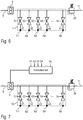
- FIG. 2 shows a schematic representation of a coating device according to the invention with a coating agent supply 8, which can be connected, for example, to a ring line and supplies a metering pump 9 with the coating agent to be applied.
- the metering pump 9 conveys the coating agent to be applied at a defined flow rate to a print head 10 with numerous nozzles N1, N2, N3, N4, ..., Nn, the nozzles N1-Nn each a control valve V1-Vn is assigned to control the flow of coating agent through the respective nozzle N1-Nn.
- control valves V1-Vn are each controlled individually by control signals Sl-Sn, the generation of the control signals Sl-Sn not being shown here for the sake of simplicity.
- the depicted coating device has a coating agent return 11, in order to allow coating agent that is not required to circulate or to divert it into a return.
- the coating agent flow through the coating agent return is set by a return valve VR, the return valve VR being activated by a control unit 12.
- the illustrated coating device has a pressure sensor 13 which measures the coating agent pressure in the print head 10, i. immediately in front of the nozzles N1-Nn.
- the pressure sensor 13 is connected on the output side to the control unit 12, which controls the feedback valve VR as a function of the measured pressure.
- the aim of the control of the return valve VR by the control unit 12 is to set a coating agent pressure in the print head 10 that is as constant as possible, regardless of the valve position of the control valves V1-Vn. Opening the control valves V1-Vn thus leads to a larger flow of coating agent through the respective nozzles N1-Nn, which, without countermeasures, initially leads to an undesirable drop in the pressure of the coating agent in the print head 10.
- the control unit 12 can counteract this by opening the return valve VR is closed accordingly, so that less coating agent is diverted via the coating agent return 11.
- the reduced coating agent flow into the coating agent return 11 then compensates as far as possible for the increased coating agent flow through the open control valves V1-Vn.
- this compensation takes place in such a way that the flow of coating agent into the print head 10 remains constant regardless of the valve position of the control valves V1-Vn, which also leads to a constant coating agent pressure in the print head 10.
- This compensation therefore leads to a constant coating agent pressure even when the control valves V1-Vn are opened or closed dynamically and thus contributes to a good coating result.
- a difference between this embodiment and the embodiment according to FIG Figure 2 consists in the fact that the control unit 12 is not connected to the pressure sensor 13, but rather receives the control signals Sl-Sn for controlling the control valves V1-Vn as input signals.
- the control unit 12 is informed about a dynamic opening or closing of the control valves Sl-Sn and can react to this with a corresponding closing or opening of the return valve VR in order to increase or decrease the coating agent flow through the nozzles N1-Nn through a corresponding one To be able to compensate for opening or closing the return valve VR so that the coating agent pressure in the print head 10 is kept as constant as possible.
- Figure 4 shows a further embodiment of a coating device according to the invention with a print head 14 with numerous control valves that are controlled by a control unit 15.
- the coating agent to be applied is fed to the pressure head 14 via a coating agent feed 16, a metering pump 17 and a flow measuring cell 18, the flow measuring cell 18 measuring the flow rate Q of the coating agent.
- the coating device also has a pressure sensor 19 which measures the coating agent pressure p in the print head 14.
- the pressure sensor 19 and the flow measuring cell 18 are connected on the output side to a controller 20 which controls the metering pump 17.
- bypass valve 21 is also provided, which is activated by the control unit 15.
- control valves in the print head 14 are dynamically closed or opened, so that the system is not in a steady state.
- the controller 20 is then operated either in a volume flow control mode or in a pressure control mode.
- the controller 20 controls the metering pump 17 in such a way that a coating agent pressure p that is as constant as possible is provided at the input of the print head 14.
- the controller 20 controls the metering pump 17 in such a way that a flow rate Q of the coating agent that is as constant as possible is set.
- the control unit 15 switches the regulator 20 between the pressure control mode and the volume flow control mode in such a way that it is switched to the pressure control mode in the unsteady state, whereas it is switched to the volume flow control mode in the steady state.
- Figure 5 shows a further exemplary embodiment of a coating device according to the invention with a print head 22 as an application device.
- the print head 22 is supplied with the paint to be coated via a ring line arrangement 23 with several lines for different colors F1, F2,..., Fn.
- the desired color F1-Fn is selected by a color changer 24 from the ring line arrangement 23, the color changer 24 feeding the selected color to a metering pump 25, which feeds the selected lacquer to the print head 22 at a defined flow rate.
- the color changer 24 is connected to a ring line arrangement 26 which forms a coating agent return.
- the color changer 24 not only has the function of selecting the desired paint F1-Fn from the ring line arrangement 23 and feeding it to the metering pump 25 and thus also to the pressure head 22. Rather, the color changer 24 also has the task of returning excess lacquer to the ring line arrangement 26 depending on the valve position of the control valves in the print head 22 in order to prevent pressure fluctuations in the print head 22 as much as possible or if no lacquer of a certain color is required.
- the coating device has a pressure sensor 27 which measures the paint pressure in the print head 22 or on the metering pump and is connected on the output side to a control unit 28.
- the control unit 28 controls the color changer 24 in such a way that pressure fluctuations in the print head 22 are avoided as far as possible.
- the control unit 28 opens or closes the return into the ring line arrangement 26 in order to compensate for a dynamic increase or decrease in the applied coating agent flow. The control unit 28 thereby ensures controlled pressure conditions in the print head 22, which contributes to a good coating result.
- Figure 6 shows a modification of Figure 2 so that to avoid repetition, first refer to the description above Figure 2 is referred to, the same reference numerals being used for corresponding details.
- a special feature of this exemplary embodiment is that, instead of the return valve VR, a return pressure regulator 29 controls the flow of coating agent into the coating agent return 11.
- the back pressure regulator 29 regulates the coating agent pressure upstream in front of the back pressure regulator 29 and thus within the print head 10 to a predetermined setpoint pressure.
- the return regulator 29 can compensate for an increase or a decrease in the applied coating agent flow if the control valves V1-Vn are opened or closed dynamically. As a result, the return pressure regulator 29 ensures an essentially constant coating agent pressure in the print head 10.
- FIG. 7 shows a modification of the embodiment according to Figure 6 , so that to avoid repetition, reference is first made to the above description, the same reference symbols being used for corresponding details.
- a special feature of this exemplary embodiment is that a control unit 30 controls the metering pump 9 as a function of the control signals S1-Sn for the control valves V1-Vn of the print head 10.
- control unit 30 can regulate the delivery rate of the metering pump 9 down in order to prevent the coating agent pressure in the pressure head 10 from overshooting.
- the return pressure regulator 29 contribute to achieving the desired pressure conditions in the print head 10, but also the control of the dosing pump 9 by the control unit 30.
- FIG 8 shows a modification of the embodiment according to Figure 6 , so that to avoid repetition, reference is first made to the above description, the same reference symbols being used for corresponding details.
- a special feature of this exemplary embodiment is that the print head 10 contains an integrated buffer memory 31, which buffers pressure fluctuations in the print head 10.
- the buffer store 31 can have a cylinder with a displaceable piston, wherein the piston can be pretensioned, for example, by a spring or by compressed air.
- the buffer memory 31 also contributes to the fact that no significant pressure fluctuations occur in the print head 10 even when the control valves V1-Vn are dynamically opened or closed, since these are buffered by the buffer memory 31.
- Figure 9 shows Figure 9 In a greatly simplified representation, the movement of a print head 32 along a programmed movement path 33 over a component surface, the print head 32 being moved over the component surface by a multi-axis painting robot with a serial robot kinematics or by a machine or a linear unit with a pulling speed v.
- nozzles 34 are arranged next to one another along a nozzle line 35.
- the nozzles 34 are arranged along the nozzle line 35 at a distance d from one another.
- the nozzle head 32 can, however, be rotated by the multi-axis painting robot, the nozzle head 32 enclosing an angle ⁇ with the nozzle line 35 relative to the programmed movement path 33. Depending on the angle of rotation ⁇ of the print head 32, a certain distance s between the adjacent nozzles 34 along the programmed movement path 33 is then established.
- the above-described situation is important because the nozzles 34 in the print head 32 must be closed one after the other when the print head 32 hits the boundary of an area to be painted. If the print head 32 along the programmed movement path 33 thus reaches the end of an area to be painted, the nozzles 34 in the print head 32 must be closed one after the other from front to back.
- a coating agent pump usually has a certain inertia and cannot react immediately to a change in the desired delivery rate, but only with a certain delay, as in Figure 10 is shown. So shows Figure 10 the change in the desired delivery rate from a target value Q1 to a lower target value Q2. It can be seen from this that the desired change in the delivery rate is implemented with a certain time constant ⁇ .
- the coating agent pump can, namely, approximately track the amount of coating agent delivered to the dynamic opening and closing of the nozzles 34.
- the invention is not restricted to the exemplary embodiments described above. Rather, a large number of variants and modifications are possible which also make use of the inventive concept and therefore fall within the scope of protection.
- the subclaims and the description disclose various aspects of the invention that enjoy protection independently of one another and in particular also independently of the features of the main claim.
- the feature of controlling the coating agent pressure or the flow rate of the coating agent is therefore not a necessary feature within the scope of the further aspects of the invention.
- the invention also includes variants in which the coating agent pump is not designed as a metering pump.
Abstract
Die Erfindung betrifft eine Beschichtungseinrichtung zur Beschichtung von Bauteilen mit einem Beschichtungsmittel, insbesondere zur Lackierung von Kraftfahrzeugkarosseriebauteilen mit einem Lack, mit einem Druckkopf (10) zur Applikation des Beschichtungsmittels auf das Bauteil, und mit einer Beschichtungsmittelversorgung (9) zur Versorgung des Druckkopfs mit dem zu applizierenden Beschichtungsmittel, wobei das Beschichtungsmittel mit einem bestimmten Beschichtungsmitteldruck und einer bestimmten Durchflussrate von der Beschichtungsmittelversorgung zu dem Druckkopf (9) strömt. Die Erfindung sieht vor, dass die Beschichtungsmittelversorgung (9) den Beschichtungsmitteldruck und/oder die Durchflussrate des Beschichtungsmittels kontrolliert einstellt. Weiterhin umfasst die Erfindung ein zugehöriges Betriebsverfahren.The invention relates to a coating device for coating components with a coating agent, in particular for painting motor vehicle body parts with a paint, with a print head (10) for applying the coating agent to the component, and with a coating agent supply (9) for supplying the print head with the applying coating agent, wherein the coating agent flows with a specific coating agent pressure and a specific flow rate from the coating agent supply to the print head (9). The invention provides that the coating agent supply (9) adjusts the coating agent pressure and / or the flow rate of the coating agent in a controlled manner. The invention also includes an associated operating method.
Description
Die Erfindung betrifft eine Beschichtungseinrichtung zur Beschichtung von Bauteilen mit einem Beschichtungsmittel, insbesondere zur Lackierung von Kraftfahrzeugkarosseriebauteilen mit einem Lack. Weiterhin betrifft die Erfindung ein entsprechendes Betriebsverfahren für eine solche Beschichtungseinrichtung.The invention relates to a coating device for coating components with a coating agent, in particular for coating motor vehicle body components with a paint. The invention also relates to a corresponding operating method for such a coating device.
Zur Serienlackierung von Kraftfahrzeugkarosseriebauteilen werden als Applikationsgerät üblicherweise Rotationszerstäuber eingesetzt, die jedoch den Nachteil eines beschränkten Auftragswirkungsgrades haben, d.h. nur ein Teil des applizierten Lacks lagert sich auf den zu beschichtenden Bauteilen ab, während der Rest des applizierten Lacks als sogenannter Overspray entsorgt werden muss.For the serial painting of motor vehicle body parts, rotary atomizers are usually used as the application device, but they have the disadvantage of a limited application efficiency, i.e. only part of the applied paint is deposited on the components to be coated, while the rest of the applied paint has to be disposed of as so-called overspray.
Weitere bekannte Zerstäubertypen sind Luftzerstäuber, Airless-Zerstäuber, Airmix-Zerstäuber und Air-Assist-Zerstäuber. Auch diese Zerstäubertypen haben jedoch den Nachteil, dass ein Sprühnebel abgegeben wird, so dass beim Beschichten unerwünschter Overspray entsteht.Other known types of atomizer are air atomizers, airless atomizers, airmix atomizers and air assist atomizers. However, these types of atomizers also have the disadvantage that a spray mist is emitted, so that undesired overspray occurs during coating.
Eine neuere Entwicklungslinie sieht dagegen als Applikationsgerät sogenannte Druckköpfe vor, wie sie beispielsweise aus
Bei den bekannten Druckköpfen erfolgt die Lackversorgung entweder drucklos, selbstansaugend, rein physikalisch nach dem Prinzip der kommunizierenden Röhrchen oder mittels eines unter Druck stehenden Lackgefäßes. Diese verschiedenen Typen von Lackversorgungen sind jedoch aus verschiedenen Gründen nachteilig.In the known print heads, the paint supply is either pressureless, self-priming, purely physically based on the principle of communicating tubes or by means of a pressurized paint container. However, these various types of paint supplies are disadvantageous for various reasons.
Bei selbstansaugenden Lackversorgungen ist das Fördervolumen und damit auch das Ausbringvolumen auf Werte von weniger als 1ml/min begrenzt.In the case of self-priming paint supplies, the delivery volume and thus also the output volume is limited to values of less than 1 ml / min.
Bei einer Druckförderung kann das Fördervolumen dagegen durch sich verändernde Randbedingungen beeinflusst werden, wie beispielsweise zusetzende Filter oder Schläuche, Querschnittsveränderungen an gequetschten, geknickten oder tordierten Schläuchen, was beispielsweise bei einer Schlauchverlegung in einem Lackierroboter auftreten kann oder bei verstopften Düsen oder Kanälen im Druckkopf.In the case of pressure delivery, on the other hand, the delivery volume can be influenced by changing boundary conditions, such as clogged filters or hoses, changes in cross-section of squeezed, kinked or twisted hoses, which can occur, for example, when hoses are laid in a painting robot or when nozzles or channels in the print head are clogged.
Da Druckköpfe nach dem Stand der Technik insbesondere Tinten mit einer Viskosität <15mPas ausstoßen, funktionieren die oben genannte Fördermethoden ausreichend gut. Auf Grund der wesentlich höheren Viskosität bei Beschichtungsmitteln, wie z.B. Lacken, sind diese Methoden aber nicht ausreichend, um ein konstantes Beschichtungsmittel-Fördervolumen sicher zu stellen.Since print heads according to the prior art in particular eject inks with a viscosity <15 mPas, the above-mentioned conveying methods work sufficiently well. Due to the significantly higher viscosity of coating agents such as Lacquers, these methods are not sufficient to ensure a constant coating agent delivery volume.
Bei der Serienlackierung von Kraftfahrzeugkarosseriebauteilen müssen jedoch qualitativ hochwertige Beschichtungen aufgebracht werden, was nur mit einer konstanten Ausbringmenge des jeweiligen Beschichtungsmittels (z.B. Lack, Kleber, Dichtmittel, Primer) realisiert werden kann. Der störende Einfluss der oben genannten Faktoren nimmt jedoch mit der Viskosität des Beschichtungsmittels zu.When painting automotive body parts in series, however, high-quality coatings must be applied, which can only be achieved with a constant application rate of the respective coating agent (e.g. paint, adhesive, sealant, Primer) can be realized. However, the disruptive influence of the above-mentioned factors increases with the viscosity of the coating agent.
Weiterhin ist zu bemerken, dass die Viskosität von Lacken zur Lackierung von Kraftfahrzeugkarosseriebauteilen so hoch ist, dass zusammen mit der Ausbringmenge und dem Rohr- und Schlauchlängen zwischen Lackreservoir und Applikationsgerät ein Druck aufgebracht werden muss, der groß genug ist, um genügend Lack zum Applikator zu fördern. Die Viskosität der Lacke kann sehr unterschiedlich sein und hängt von einigen Parametern ab, wie z.B. Temperatur und Scherung.It should also be noted that the viscosity of paints for painting vehicle body components is so high that, together with the application rate and the pipe and hose lengths, a pressure must be applied between the paint reservoir and the application device that is high enough to apply enough paint to the applicator promote. The viscosity of the paints can be very different and depends on some parameters, such as Temperature and shear.
Beim Einsatz der bekannten Druckköpfe als Applikationsgerät bei der Serienlackierung von Kraftfahrzeugkarosseriebauteilen ist die Lackversorgung also in der Praxis noch unbefriedigend.When the known print heads are used as an application device in the series painting of motor vehicle body parts, the paint supply is still unsatisfactory in practice.
Zum technischen Hintergrund der Erfindung ist auch hinzuweisen auf
Der Erfindung liegt deshalb die Aufgabe zugrunde, dieses Problem zu lösen.The invention is therefore based on the object of solving this problem.
Diese Aufgabe wird durch eine erfindungsgemäße Beschichtungseinrichtung bzw. ein entsprechendes Betriebsverfahren gemäß den unabhängigen Ansprüchen gelöst.This object is achieved by a coating device according to the invention or a corresponding operating method according to the independent claims.
Die Erfindung umfasst die allgemeine technische Lehre, den Beschichtungsmitteldruck und/oder die Durchflussart des Beschichtungsmittels kontrolliert einzustellen, um bei der Applikation von Beschichtungsmittel (z.B. Lack, Kleber, Dichtmittel, Primer, etc.) mit einem Druckkopf definierte Applikationsbedingungen herzustellen, damit qualitativ hochwertige Beschichtungen aufgebracht werden können.The invention comprises the general technical teaching of adjusting the coating agent pressure and / or the type of flow of the coating agent in a controlled manner in order to be able to use the coating agent (e.g. paint, adhesive, sealant, Primer, etc.) to create defined application conditions with a print head so that high-quality coatings can be applied.
Der im Rahmen der Erfindung verwendete Begriff eines Beschichtungsmittels ist allgemein zu verstehen und umfasst beispielsweise Lacke (z.B. Wasserlack, lösemittelbasierter Lack, Basislack, Klarlack), Wachse (z.B. Konservierungswachs), Dickstoffe, Dichtstoffe, Dämmstoffe und Klebstoffe.The term coating agent used in the context of the invention is to be understood in general terms and includes, for example, paints (e.g. water-based paint, solvent-based paint, basecoat, clearcoat), waxes (e.g. preservation wax), thick substances, sealants, insulation materials and adhesives.
Die erfindungsgemäße Beschichtungseinrichtung weist zunächst in Übereinstimmung mit dem Stand der Technik einen Druckkopf zur Applikation des Beschichtungsmittels (z.B. Lack, Kleber, Dichtmittel, Primer, etc.) auf das Bauteil (z.B. Kraftfahrzeugkarosseriebauteil) auf. Der im Rahmen der Erfindung verwendete Begriff eines Druckkopfs ist allgemein zu verstehen und dient lediglich zur Abgrenzung von Zerstäubern (z.B. Rotationszerstäuber, Scheibenzerstäuber, Airless-Zerstäuber, Airmix-Zerstäuber, Ultraschallzerstäuber), die einen Sprühnebel des zu applizierenden Beschichtungsmittels abgeben. Im Gegensatz dazu gibt der Druckkopf einen räumlich eng begrenzten Beschichtungsmittelstrahl ab. Derartige Druckköpfe sind an sich aus dem Stand der Technik bekannt und beispielsweise in
Darüber hinaus weist die erfindungsgemäße Beschichtungseinrichtung eine Beschichtungsmittelversorgung auf, um den Druckkopf mit dem zu applizierenden Beschichtungsmittel zu versorgen, wobei sich ein bestimmter Beschichtungsmitteldruck und eine bestimmte Durchflussrate des Beschichtungsmittels einstellen.In addition, the coating device according to the invention has a coating agent supply in order to supply the print head with the coating agent to be applied, a specific coating agent pressure and a specific flow rate of the coating agent being established.
Die Erfindung sieht nun vor, dass die Beschichtungsmittelversorgung den Beschichtungsmitteldruck und/oder die Durchflussrate des Beschichtungsmittels kontrolliert einstellt, um definierte Applikationsbedingungen herzustellen, was für die Aufbringung qualitativ hochwertiger Beschichtungen wichtig ist.The invention now provides that the coating agent supply adjusts the coating agent pressure and / or the flow rate of the coating agent in a controlled manner in order to produce defined application conditions, which is important for the application of high-quality coatings.
In einem Ausführungsbeispiel der Erfindung weist die Beschichtungsmittelversorgung eine Dosierpumpe auf, die das Beschichtungsmittel dosiert und zu dem Druckkopf fördert. Der Begriff einer Dosierpumpe impliziert hierbei, dass die Durchflussrate im Wesentlichen unabhängig ist von Druckverhältnissen am Eingang und am Ausgang der Dosierpumpe. Dies bedeutet, dass entsprechend der Ansteuerung der Dosierpumpe eine definierte Durchflussrate eingestellt werden kann, was für qualitativ hochwertige Beschichtungen wichtig ist.In one exemplary embodiment of the invention, the coating agent supply has a metering pump which meters the coating agent and delivers it to the print head. The concept of a metering pump here implies that the flow rate is essentially independent of the pressure conditions at the inlet and the outlet of the metering pump. This means that a defined flow rate can be set according to the control of the metering pump, which is important for high-quality coatings.
Beispielsweise kann es sich bei der Dosierpumpe um eine Zahnradpumpe, eine Taumelkolbenpumpe oder eine Mikrozahnradpumpe handeln, um nur einige Beispiele zu nennen.For example, the metering pump can be a gear pump, a wobble piston pump or a micro gear pump, to name just a few examples.
Hierbei ist es vorteilhaft, wenn die Dosierpumpe mit einem Spülmittel spülbar ist, um Beschichtungsmittelreste aus der Dosierpumpe auszuspülen. Dies ist insbesondere dann vorteilhaft, wenn die Dosierpumpe eingesetzt werden soll, um verschiedene Farben nacheinander zu fördern. Bei einem Farbwechsel kann die Dosierpumpe dann zunächst mit einem Spülmittel gespült werden, um Beschichtungsmittelreste der alten Farbe aus der Dosierpumpe auszuspülen. Alternativ kann die Dosierpumpe zunächst ausgeblasen und dann gespült werden. Weiterhin kann die Dosierpumpe abwechselnd mit Spülmittel und Pulsluft gereinigt werden.It is advantageous here if the metering pump can be flushed with a rinsing agent in order to flush out coating agent residues from the metering pump. This is particularly advantageous when the metering pump is to be used to convey different colors one after the other. In the event of a color change, the metering pump can then first be rinsed with a detergent in order to rinse out any remaining paint from the metering pump. Alternatively, the dosing pump can first be blown out and then rinsed. Furthermore, the dosing pump can be cleaned alternately with detergent and pulsed air.
Alternativ besteht im Rahmen der Erfindung die Möglichkeit, dass die Beschichtungsmittelversorgung einen Kolbendosierer aufweist, um das Beschichtungsmittel kontrolliert zuzuführen. Hierbei wird das Beschichtungsmittel von einem verschiebbaren Kolben aus einem Zylinder herausgedrückt, so dass die Kolbenstellung unmittelbar die Menge des applizierten Beschichtungsmittels bestimmt.Alternatively, within the scope of the invention, there is the possibility that the coating agent supply is a piston dispenser has in order to supply the coating agent in a controlled manner. In this case, the coating agent is pressed out of a cylinder by a displaceable piston, so that the piston position directly determines the amount of coating agent applied.
Der Kolbendosierer kann beispielsweise am oder in dem Applikator (Druckkopf) angeordnet sein, vor der Roboterhandachse, hinter der Roboterhandachse, an dem distalen Roboterarm ("Arm 2") oder an dem proximalen Roboterarm ("Arm 1"), mitfahrend auf einer linearen Verfahrachse, an der Kabinenwand der Lackierkabine oder außerhalb der Lackierkabine.The piston dispenser can for example be arranged on or in the applicator (print head), in front of the robot hand axis, behind the robot hand axis, on the distal robot arm ("
Eine andere Erfindungsvariante sieht dagegen einen Kartuschendosierer vor mit einer beschichtungsmittelgefüllten Kartusche mit einem Kartuschenauslass zur Abgabe des Beschichtungsmittels und einem Kartuscheneinlass zur Einleitung eines Verdrängungsfluids, welches das in der Kartusche befindliche Beschichtungsmittel verdrängt und durch den Kartuschenauslass ausstößt. Die Durchflussrate des Beschichtungsmittels an dem Druckkopf kann hierbei durch eine Steuerung des in die Kartusche eingeleiteten Verdrängungsfluids (z.B. zuerst Lösemittel, dann Druckluft) genau gesteuert werden, so dass auch auf diese Weise definierte Applikationsbedingungen eingestellt werden können.Another variant of the invention, on the other hand, provides a cartridge dispenser with a cartridge filled with coating agent, with a cartridge outlet for dispensing the coating agent and a cartridge inlet for introducing a displacement fluid which displaces the coating agent in the cartridge and ejects it through the cartridge outlet. The flow rate of the coating agent on the print head can be precisely controlled by controlling the displacement fluid introduced into the cartridge (e.g. first solvent, then compressed air), so that defined application conditions can also be set in this way.
In einer anderen Erfindungsvariante weist die Beschichtungsmittelversorgung ein Beschichtungsmittelreservoir (z.B. Ringleitung) auf, um das zu applizierende Beschichtungsmittel bereit zu stellen, wobei die definierten Applikationsbedingungen durch einen Druckregler eingestellt werden, der den Beschichtungsmitteldruck regelt. Hierbei kann auch ein Drucksensor vorgesehen werden, um den Beschichtungsmitteldruck zu messen, wobei die Messgröße des Beschichtungsmitteldrucks dann dem Druckregler bereitgestellt werden kann.In another variant of the invention, the coating agent supply has a coating agent reservoir (eg, ring line) to provide the coating agent to be applied, the defined application conditions being set by a pressure regulator that regulates the coating agent pressure. In this case, a pressure sensor can also be provided in order to measure the coating agent pressure, the measured variable of the coating agent pressure can then be provided to the pressure regulator.
In einem bevorzugten Ausführungsbeispiel der Erfindung weist die Beschichtungsmittelversorgung eine Beschichtungsmittelpumpe auf, um das Beschichtungsmittel zu dem Druckkopf zu fördern. Bei der Beschichtungsmittelpumpe handelt es sich vorzugsweise um eine Dosierpumpe in dem vorstehend beschriebenen Sinne, jedoch kann in diesem Ausführungsbeispiel auch ein anderer Pumpentyp als Beschichtungsmittelpumpe eingesetzt werden.In a preferred exemplary embodiment of the invention, the coating agent supply has a coating agent pump in order to convey the coating agent to the print head. The coating agent pump is preferably a metering pump in the sense described above, but in this exemplary embodiment another type of pump can also be used as the coating agent pump.
Darüber hinaus weist die Beschichtungsmittelversorgung in diesem Ausführungsbeispiel einen Drucksensor auf, der den Beschichtungsmitteldruck an dem Druckkopf misst, d.h. stromaufwärts vor dem Druckkopf, innerhalb des Druckkopfs oder unmittelbar an einer Düse des Druckkopfs oder an der Dosierpumpe.In addition, the coating agent supply in this embodiment has a pressure sensor which measures the coating agent pressure at the printhead, i. E. upstream of the printhead, inside the printhead or directly on a nozzle of the printhead or on the metering pump.
Ferner weist dieses Ausführungsbeispiel im Falle eines Druckreglers auch eine Durchflussmesszelle auf, welche die von der Beschichtungsmittelpumpe zu dem Druckkopf geförderte Durchflussrate misst, insbesondere den Volumenstrom oder den Massenstrom des geförderten Beschichtungsmittels.Furthermore, in the case of a pressure regulator, this exemplary embodiment also has a flow measuring cell which measures the flow rate conveyed by the coating agent pump to the print head, in particular the volume flow or the mass flow of the conveying agent.
Schließlich weist dieses Ausführungsbeispiel noch einen Regler auf, der die Beschichtungsmittelpumpe in Abhängigkeit von dem gemessenen Beschichtungsmitteldruck und/oder in Abhängigkeit von der gemessenen Durchflussrate des Beschichtungsmittels ansteuert.Finally, this exemplary embodiment also has a controller which controls the coating agent pump as a function of the measured coating agent pressure and / or as a function of the measured flow rate of the coating agent.
Weiterhin ist bei diesem Ausführungsbeispiel vorzugsweise eine Bypass-Leitung vorgesehen, um die Beschichtungsmittelpumpe zu umgehen. Hierbei ist auch ein Bypass-Ventil vorgesehen, das den Beschichtungsmittelstrom durch die Bypass-Leitung steuert. Die Abführung von Beschichtungsmittel über die Bypass-Leitung ermöglicht ebenfalls eine Kontrolle der Druckverhältnisse an dem Druckkopf und kann auch zum Spülen und Andrücken dienen.Furthermore, in this exemplary embodiment, a bypass line is preferably provided in order to bypass the coating agent pump. A bypass valve is also provided here which controls the flow of coating agent through the bypass line. The removal of the coating agent via the bypass line also enables the pressure conditions on the print head to be checked and can also be used for flushing and pressing.
Der bereits vorstehend erwähnte Regler steuert die Beschichtungsmittelpumpe vorzugsweise in Abhängigkeit von dem gemessenen Beschichtungsmitteldruck und/oder in Abhängigkeit von dem gemessenen Beschichtungsmittelstrom, wobei verschiedene Regelungsziele möglich sind. Ein Regelungsziel sieht vor, dass der Beschichtungsmitteldruck auf einen vorgegebenen Soll-Druck geregelt wird. Ein anderes Regelungsziel sieht dagegen vor, dass die Durchflussrate des Beschichtungsmittels auf eine vorgegebene Soll-Durchflussrate geregelt wird.The regulator already mentioned above controls the coating agent pump preferably as a function of the measured coating agent pressure and / or as a function of the measured coating agent flow, with various control objectives being possible. A regulation objective provides that the coating agent pressure is regulated to a predetermined target pressure. Another control objective, on the other hand, provides that the flow rate of the coating agent is controlled to a predetermined target flow rate.
Vorzugsweise ist der Regler deshalb umschaltbar zwischen einem Druckregelbetrieb und einem Mengenstromregelbetrieb. In dem Druckregelbetrieb regelt der Regler den Beschichtungsmitteldruck auf den vorgegebenen Soll-Druck ein. In dem Mengenstromregelbetrieb regelt der Regler dagegen die Durchflussrate des Beschichtungsmittels auf die vorgegebene Soll-Durchflussrate ein.The controller can therefore preferably be switched between pressure control mode and mass flow control mode. In the pressure control mode, the controller regulates the coating agent pressure to the specified target pressure. In the mass flow control mode, on the other hand, the controller regulates the flow rate of the coating agent to the specified target flow rate.
Die Umschaltung zwischen diesen beiden Betriebsarten (Druckregelbetrieb und Mengenstromregelbetrieb) kann im Rahmen der Erfindung bei diesem Ausführungsbeispiel durch eine Steuereinheit erfolgen. Hierbei ist zu berücksichtigen, dass der Druckkopf teilweise in einem stationären Zustand und teilweise in einem instationären Zustand betrieben wird. Im stationären Zustand (eingeschwungener Betrieb) werden keine Düsen an dem Druckkopf geöffnet oder geschlossen, wobei ein möglichst konstanter Mengenstrom des Beschichtungsmittels appliziert werden soll. Im instationären Zustand des Druckkopfs werden dagegen Düsenventile geschlossen oder geöffnet, was eine entsprechend dynamische Anpassung des applizierten Mengenstroms erfordert. Die Steuereinheit schaltet den Regler dann vorzugsweise in den Mengenstromregelbetrieb, wenn der Druckkopf in einem stationären Zustand betrieben wird, in dem keine Düsenventile des Druckkopfs geöffnet oder geschlossen werden. Die Steuereinheit schaltet den Regler dagegen vorzugsweise in den Druckregelbetrieb, wenn der Druckkopf in einem instationären Zustand betrieben wird, in dem Düsenventile des Druckkopfs dynamisch geöffnet oder geschlossen werden.The switchover between these two operating modes (pressure control mode and volume flow control mode) can be carried out by a control unit within the scope of the invention in this exemplary embodiment. It must be taken into account here that the print head is operated partly in a stationary state and partly in a non-stationary state. In the steady state (steady-state operation), no nozzles are opened or closed on the print head, and the aim is to apply a constant flow of the coating agent. In the unsteady state of the print head, on the other hand, nozzle valves are closed or opened, which results in a corresponding dynamic adjustment of the applied volume flow requires. The control unit then preferably switches the regulator into the volume flow control mode when the print head is operated in a stationary state in which no nozzle valves of the print head are opened or closed. The control unit, on the other hand, preferably switches the regulator to pressure control mode when the print head is operated in a transient state in which nozzle valves of the print head are dynamically opened or closed.
Die Steuerung kann die unterschiedlichen Zustände auf Basis des Beschichtungsprogramms zeitlich vorausberechnen, da zu jedem Zeitpunkt des Beschichtungsablaufs bekannt ist, welche Düse geöffnet bzw. geschlossen ist. So kann für jeden beliebigen Zeitpunkt der erforderliche Beschichtungsmittel-Volumenstrom berechnet werden bzw. die Zeitpunkte der Umschaltung vom Volumenregelbetrieb in den Druckregelbetrieb. Dies erhöht die Dynamik der Regelung wesentlich.The control can calculate the different states in advance on the basis of the coating program, since it is known at any point in time during the coating process which nozzle is open or closed. In this way, the required volume flow of the coating agent can be calculated for any point in time, or the points in time of switching from volume control mode to pressure control mode. This increases the dynamics of the regulation significantly.
Darüber hinaus kann die Steuereinheit auch das vorstehend erwähnte Bypass-Ventil ansteuern und zwar in Abhängigkeit von dem stationären oder instationären Zustand des Druckkopfs.In addition, the control unit can also control the aforementioned bypass valve, specifically as a function of the stationary or unsteady state of the print head.
In einem anderen Ausführungsbeispiel der Erfindung weist die Beschichtungsmittelversorgung eine Beschichtungsmittelzuführung (z.B. Ringleitung), eine Beschichtungsmittelrückführung (z.B. Ringleitung) und ein Druckstellglied (z.B. Steuerventil, Druckregler) auf, das den Beschichtungsmittelstrom von der Beschichtungsmittelzuführung in die Beschichtungsmittelrückführung einstellt. Die Rückführung führt das Beschichtungsmittel vorzugsweise der Wiederverwendung zu, z.B. zurück in die Ringleitung, zum Lackbehälter oder zu einem anderen Applikator. Darüber hinaus weist die Beschichtungsmittelversorgung in diesem Ausführungsbeispiel einen Beschichtungsmittelauslass (z.B. Düse des Druckkopfs) auf, der mit der Beschichtungsmittelzuführung verbunden werden kann oder mit der Beschichtungsmittelzuführung verbunden ist.In another exemplary embodiment of the invention, the coating agent supply has a coating agent feed (e.g. ring line), a coating agent return (e.g. ring line) and a pressure actuator (e.g. control valve, pressure regulator) that adjusts the coating agent flow from the coating agent feed to the coating agent return. The recycling preferably leads the coating agent to reuse, for example back into the ring line, to the paint container or to another applicator. In addition, the coating agent supply in this exemplary embodiment has a coating agent outlet (for example nozzle of the print head) that connects to the coating agent supply can be connected or is connected to the coating agent supply.
Bei diesem Ausführungsbeispiel kann das Druckstellglied - wie bereits vorstehend kurz erwähnt wurde - als Rücklaufdruckregler ausgebildet sein, der den Beschichtungsmittelstrom in die Beschichtungsmittelrückführung einstellt und dadurch den Beschichtungsmitteldruckstrom aufwärts vor dem Rücklaufdruckregler und damit auch an den Beschichtungsmittelauslass auf den vorgegebenen Soll-Druck regelt.In this embodiment, the pressure actuator can - as mentioned briefly above - be designed as a return pressure regulator, which adjusts the coating agent flow into the coating agent return and thereby regulates the coating agent pressure flow upwards before the return pressure regulator and thus also to the coating agent outlet to the specified target pressure.
Alternativ besteht - wie bereits vorstehend kurz erwähnt - die Möglichkeit, dass das Druckstellglied ein steuerbares Rücklaufventil ist, das den Beschichtungsmittelstrom in die Beschichtungsmittelrückführung einstellt, um definierte Applikationsverhältnisse an dem Beschichtungsmittelauslass herzustellen. Wie zuvor beschrieben, kann die Steuerung auch die Stellung des Rücklaufventils zeitlich im Voraus berechnen und dadurch die Regeldynamik erhöhen.As an alternative - as mentioned briefly above - there is the possibility that the pressure actuator is a controllable return valve which adjusts the coating agent flow into the coating agent return in order to establish defined application conditions at the coating agent outlet. As described above, the control can also calculate the position of the return valve in advance and thereby increase the control dynamics.
In einer besonders vorteilhaften Variante dieses Ausführungsbeispiels ist das Druckstellglied ein doppelt wirkendes Steuerventil, das in Abhängigkeit von seiner Ventilstellung entweder die Beschichtungsmittelzuführung mit dem Beschichtungsmittelauslass verbindet und dabei die Beschichtungsmittelrückführung verschließt, oder die Beschichtungsmittelzuführung mit der Beschichtungsmittelrückführung verbindet und dabei den Beschichtungsmittelauslass verschließt. Der zugeführte Beschichtungsmittelstrom wird also von dem Druckstellglied entweder in die Beschichtungsmittelrückführung oder durch den Beschichtungsmittelauslass geleitet, so dass der geförderte Beschichtungsmittelstrom mengenmäßig konstant bleiben kann und nur die Richtung des Beschichtungsmittelstroms verändert wird, nämlich entweder in die Beschichtungsmittelrückführung oder durch den Beschichtungsmittelauslass. Beispielsweise kann dann das doppelt wirkende Steuerventil ein hantelförmiges oder wippenförmiges Ventilelement aufweisen.In a particularly advantageous variant of this exemplary embodiment, the pressure actuator is a double-acting control valve which, depending on its valve position, either connects the coating agent feed to the coating agent outlet and thereby closes the coating agent return, or connects the coating agent feed to the coating agent return and thereby closes the coating agent outlet. The flow of coating agent supplied is thus passed by the pressure actuator either into the coating agent return or through the coating agent outlet, so that the amount of the conveyed coating agent flow can remain constant and only the direction of the coating agent flow is changed, namely either into the coating agent return or through the coating agent outlet. For example, the double-acting control valve can then have a dumbbell-shaped or rocker-shaped valve element.
Vorzugsweise ist dieses doppelt wirkende Steuerventil in dem Druckkopf angeordnet. Es besteht jedoch im Rahmen der Erfindung auch die Möglichkeit, dass das doppelt wirkende Steuerventil stromaufwärts vor dem Druckkopf angeordnet ist.This double-acting control valve is preferably arranged in the print head. However, within the scope of the invention there is also the possibility that the double-acting control valve is arranged upstream in front of the print head.
Weiterhin ist zu erwähnen, dass der von dem doppelt wirkenden Steuerventil gesteuerte Beschichtungsmittelauslass vorzugsweise eine Düsenöffnung des Druckkopfs ist. In diesem Fall ist das doppelt wirkende Steuerventil also unmittelbar an der Düsenöffnung angeordnet.It should also be mentioned that the coating agent outlet controlled by the double-acting control valve is preferably a nozzle opening of the print head. In this case, the double-acting control valve is therefore arranged directly on the nozzle opening.
Ferner ist zu erwähnen, dass das doppelt wirkende Steuerventil zu der Beschichtungsmittelrückführung hin und zu dem Beschichtungsmittelauslass hin den gleichen freien Strömungsquerschnitt aufweist, was in beiden Ventilstellungen zu demselben Strömungswiderstand führt.It should also be mentioned that the double-acting control valve has the same free flow cross section towards the coating agent return and towards the coating agent outlet, which leads to the same flow resistance in both valve positions.
In einem weiteren Ausführungsbeispiel der Erfindung weist die Beschichtungsmittelversorgung zur Förderung des Beschichtungsmittels eine Beschichtungsmittelpumpe mit einer einstellbaren Förderleistung auf, insbesondere eine Dosierpumpe. Hierbei hat der Düsenkopf mehrere Beschichtungsmitteldüsen zur Abgabe des Beschichtungsmittels, wobei den einzelnen Beschichtungsmitteldüsen jeweils ein Düsenventil zugeordnet ist, so dass die einzelnen Beschichtungsmitteldüsen individuell angesteuert werden können. Darüber hinaus ist eine Kontrolleinheit vorgesehen zur Einstellung der Förderleistung der Beschichtungsmittelpumpe, wobei die Kontrolleinheit die Anzahl der geöffneten Düsenventile ermittelt und in Abhängigkeit von der Anzahl der geöffneten Düsenventile die Förderleistung der Beschichtungsmittelpumpe einstellt. Die Kontrolleinheit kann die Anzahl der geöffneten Düsenventile beispielsweise durch Abfrage der Steuersignale für die einzelnen Düsenventile ermitteln oder wie vorstehend beschrieben wurde. Die Förderleistung der Beschichtungsmittelpumpe wird dann entsprechend der benötigten Fördermenge in Abhängigkeit von der Anzahl der geöffneten Düsenventile eingestellt. Hierbei ist zu erwähnen, dass die Kontrolleinheit vorzugsweise eine sehr geringe Reaktionszeit von weniger als 100ms, 60ms, 10ms, 1ms, 100ps oder sogar weniger als 10ps hat, um auf das dynamische Öffnen und Schließen der einzelnen Düsenventile hinreichend schnell reagieren zu können.In a further exemplary embodiment of the invention, the coating agent supply for conveying the coating agent has a coating agent pump with an adjustable delivery rate, in particular a metering pump. Here, the nozzle head has several coating agent nozzles for dispensing the coating agent, a nozzle valve being assigned to each of the individual coating agent nozzles, so that the individual coating agent nozzles can be controlled individually. In addition, a control unit is provided for setting the delivery rate of the coating agent pump, the control unit determining the number of open nozzle valves and the delivery rate depending on the number of open nozzle valves the coating agent pump adjusts. The control unit can determine the number of open nozzle valves, for example, by querying the control signals for the individual nozzle valves or as described above. The delivery rate of the coating agent pump is then set according to the required delivery rate as a function of the number of open nozzle valves. It should be mentioned here that the control unit preferably has a very short response time of less than 100ms, 60ms, 10ms, 1ms, 100ps or even less than 10ps in order to be able to react quickly enough to the dynamic opening and closing of the individual nozzle valves.
Eine andere Möglichkeit zur Kontrolle der Applikationsbedingungen an dem Druckkopf besteht darin, einen Pufferspeicher vorzusehen, der das Beschichtungsmittel aufnimmt und Druckschwankungen des Beschichtungsmittels abpuffert.Another possibility for checking the application conditions on the print head is to provide a buffer store which receives the coating agent and buffers pressure fluctuations in the coating agent.
Der Pufferspeicher ist vorzugsweise unmittelbar in dem Drucckopf angeordnet, um dort Druckschwankungen möglichst effektiv abzupuffern. Es besteht jedoch alternativ auch die Möglichkeit, dass der Pufferspeicher außerhalb des Druckkopfs und stromaufwärts vor dem Druckkopf angeordnet ist.The buffer store is preferably arranged directly in the pressure head in order to buffer pressure fluctuations there as effectively as possible. Alternatively, however, there is also the possibility that the buffer store is arranged outside of the print head and upstream in front of the print head.
Beispielsweise kann der Pufferspeicher durch einen Zylinder mit einem verschiebbaren Kolben realisiert werden, wobei der Kolben beispielsweise durch eine Feder, Druckluft, einem elektrischen Aktor, einem piezoelektrischen Aktor oder einem magnetischen Aktor vorgespannt werden kann.For example, the buffer store can be implemented by a cylinder with a displaceable piston, wherein the piston can be preloaded, for example, by a spring, compressed air, an electrical actuator, a piezoelectric actuator or a magnetic actuator.
Weiterhin ist zu erwähnen, dass der Druckkopf vorzugsweise durch einen Manipulator (z.B. Lackierroboter) mit einer seriellen Roboterkinematik entlang einer programmierten Bewegungsbahn mit einer bestimmten Ziehgeschwindigkeit über die Oberfläche des zu beschichtenden Bauteils bewegt wird. Beim Überfahren einer Bauteilkante müssen die einzelnen Beschichtungsmitteldüsen des Druckkopfs dann nacheinander geschlossen bzw. geöffnet werden, was auch eine entsprechend dynamische Anpassung der Förderleistung der Beschichtungsmittelpumpe erforderlich macht. Hierzu ist zu berücksichtigen, dass die erforderliche Reaktionszeit der Beschichtungsmittelpumpe von der Ziehgeschwindigkeit des Druckkopfs und von dem Abstand der benachbarten Beschichtungsmitteldüsen entlang der programmierten Bewegungsbahn abhängig ist. Die Beschichtungsmittelpumpe weist deshalb vorzugsweise eine ausreichend kurze Zeitkonstante auf, wobei die Zeitkonstante der Beschichtungsmittelpumpe die Zeitspanne angibt, die bei einer Änderung der gewünschten Fördermenge vergeht, bis 63,2% (1-1/e) der gewünschten Änderung der Fördermenge umgesetzt ist. Es gilt deshalb vorzugsweise folgende Formel: ![]()
- s:
- Abstand der benachbarten Beschichtungsmitteldüsen in dem Druckkopf entlang der programmierten Bewegungsbahn,
- v:
- Ziehgeschwindigkeit des Druckkopfs entlang der programmierten Roboterbahn,
- τ:
- Zeitkonstante der Beschichtungsmittelpumpe.
- s:
- Distance between the adjacent coating agent nozzles in the print head along the programmed movement path,
- v:
- Pulling speed of the print head along the programmed robot path,
- τ:
- Time constant of the coating agent pump.
Allerdings ist zu berücksichtigen, dass der Abstand der benachbarten Beschichtungsmitteldüsen entlang der programmierten Bewegungsbahn auch durch eine Verdrehung des Druckkopfs beeinflusst werden kann. So sind die Beschichtungsmitteldüsen üblicherweise entlang einer Düsenlinie in dem Druckkopf angeordnet, wobei der Druckkopf mit der Düsenlinie relativ zu der programmierten Bewegungsbahn drehbar ist, so dass die Düsenlinie mit der programmierten Bewegungsbahn einen Druckkopfwinkel einschließt. Der Druckkopf wird dann vorzugsweise so gedreht und bewegt, dass folgende Formel gilt: ![]()
- s:
- Abstand der benachbarten Beschichtungsmitteldüsen in dem Druckkopf entlang der programmierten Bewegungsbahn,
- d:
- Abstand der benachbarten Beschichtungsmitteldüsen entlang der Düsenlinie,
- v:
- Ziehgeschwindigkeit des Druckkopfs entlang der programmierten Roboterbahn,
- τ:
- Zeitkonstante der Beschichtungsmittelpumpe,
- α:
- Drehwinkel zwischen der Düsenlinie und der programmierten Bewegungsbahn des Druckkopfs.
- s:
- Distance between the adjacent coating agent nozzles in the print head along the programmed movement path,
- d:
- Distance between the adjacent coating agent nozzles along the nozzle line,
- v:
- Pulling speed of the print head along the programmed robot path,
- τ:
- Time constant of the coating agent pump,
- α:
- Angle of rotation between the nozzle line and the programmed movement path of the printhead.
Allgemein ist zu erwähnen, dass der Druckkopf einen eng begrenzten Beschichtungsmittelstrahl abgibt im Gegensatz zu einem Sprühnebel, wie es beispielsweise bei Rotationszerstäubern der Fall ist.In general, it should be mentioned that the print head emits a narrowly limited jet of coating agent in contrast to a spray mist, as is the case, for example, with rotary atomizers.
Beispielsweise kann der Druckkopf einen Tröpfchenstrahl oder auch nur einzelne Tropfen abgeben im Gegensatz zu einem in Strahllängsrichtung zusammenhängenden Beschichtungsmittelstrahl.For example, the print head can emit a jet of droplets or only individual drops in contrast to a jet of coating agent that is contiguous in the longitudinal direction of the jet.
Alternativ besteht jedoch auch die Möglichkeit, dass der Druckkopf einen in Strahllängsrichtung zusammenhängenden Beschichtungsmittelstrahl abgibt im Gegensatz zu dem vorstehenden erwähnten Tröpfchenstrahl.Alternatively, however, there is also the possibility that the print head emits a coating agent jet that is coherent in the longitudinal direction of the jet, in contrast to the aforementioned droplet jet.
Die erfindungsgemäße Kontrolle des Beschichtungsmitteldrucks erfolgt vorzugsweise mit einer maximalen Schwankungsbreite von höchstens ±500mbar, ±200mbar, ±100mbar oder sogar höchstens ±50mbar.The inventive control of the coating agent pressure is preferably carried out with a maximum fluctuation range of at most ± 500 mbar, ± 200 mbar, ± 100 mbar or even at most ± 50mbar.
Ferner ist zu erwähnen, dass der Druckkopf vorzugsweise einen Auftragswirkungsgrad von mindestens 80%, 90%, 95% oder sogar 99% aufweist, so dass im Wesentlichen das gesamte applizierte Beschichtungsmittel vollständig auf dem Bauteil abgelagert wird, ohne dass Overspray entsteht.It should also be mentioned that the print head preferably has an application efficiency of at least 80%, 90%, 95% or even 99%, so that essentially all of the applied coating agent is completely deposited on the component without overspray occurring.
Der Druckkopf ermöglicht vorzugsweise eine Flächenbeschichtungsleistung von mindestens 0,5 m2/min, 1m2/min, 2m2/min oder mindestens 3m2/min, d.h. der Druckkopf kann eine entsprechende Bauteiloberfläche innerhalb der genannten Zeitspanne beschichten.The printhead preferably enables a surface coating performance of at least 0.5 m 2 / min, 1 m 2 / min, 2 m 2 / min or at least 3 m 2 / min, ie the printhead can coat a corresponding component surface within the specified time period.
Darüber hinaus ist zu erwähnen, dass der Mengenstrom des applizierten Beschichtungsmittels und damit die Austrittsgeschwindigkeit des Beschichtungsmittels vorzugsweise so eingestellt wird, dass das Beschichtungsmittel nach dem Auftreffen auf das Bauteil nicht von dem Bauteil abprallt.In addition, it should be mentioned that the flow rate of the applied coating agent and thus the exit speed of the coating agent is preferably adjusted so that the coating agent does not bounce off the component after it hits the component.
Beispielsweise kann die Austrittsgeschwindigkeit des Beschichtungsmittels im Bereich von 5m/s bis 30 m/s liegen.For example, the exit speed of the coating agent can be in the range from 5 m / s to 30 m / s.
Der Applikationsabstand zwischen Düse und Bauteiloberfläche kann beispielsweise im Bereich von 4mm bis 200mm, insbesondere von 5mm bis 100mm, 5mm bis 50mm, 10mm bis40mm liegen.The application distance between the nozzle and the component surface can be, for example, in the range from 4mm to 200mm, in particular from 5mm to 100mm, 5mm to 50mm, 10mm to 40mm.
Auch hinsichtlich des applizierten Beschichtungsmittels bestehen im Rahmen der Erfindung verschiedene Möglichkeiten. Vorzugsweise handelt es sich bei dem Beschichtungsmittel jedoch um einen Lack, wie beispielsweise einem Basislack, einem Klarlack, einem Effektlack, einem Mica-Lack oder einem Metallic-Lack. Beispielsweise können diese Lacke wasserbasierende oder lösemittel-basierende Lacke sein.There are also various possibilities within the scope of the invention with regard to the applied coating agent. However, the coating agent is preferably a lacquer, such as, for example, a basecoat, a clear lacquer, an effect lacquer, a mica lacquer or a metallic lacquer. For example, these paints can be water-based or solvent-based paints.
Zum Ausstoßen des zu applizierenden Beschichtungsmittels weist der Druckkopf vorzugsweise mindestens einen elektrisch ansteuerbaren Aktor auf, beispielsweise einen Magnetaktor oder einen Piezoaktor. Pneumatische Ventile oder Antriebe sind auch denkbar.In order to eject the coating agent to be applied, the print head preferably has at least one electrically controllable actuator, for example a magnetic actuator or a piezo actuator. Pneumatic valves or drives are also conceivable.
Schließlich ist noch zu erwähnen, dass die Erfindung auch ein entsprechendes Betriebsverfahren umfasst, wobei die einzelnen Schritte des erfindungsgemäßen Betriebsverfahrens bereits aus der vorstehenden Beschreibung der erfindungsgemäßen Beschichtungseinrichtung ersichtlich sind und deshalb nicht näher beschrieben werden müssen.Finally, it should also be mentioned that the invention also includes a corresponding operating method, the individual steps of the operating method according to the invention already being evident from the above description of the coating device according to the invention and therefore not needing to be described in more detail.
Andere vorteilhafte Weiterbildungen der Erfindung sind in den Unteransprüchen gekennzeichnet oder werden nachstehend zusammen mit der Beschreibung der bevorzugten Ausführungsbeispiele der Erfindung anhand der Figuren näher erläutert. Es zeigen:
- Figur 1A
- eine schematische Darstellung eines doppelt wirkenden Steuerventils zur Steuerung des Lackstroms durch eine Düse des Druckkopfs in einer Öffnungsstellung,
- Figur 1B
- das doppelt wirkende Steuerventil gemäß
Figur 1A in einer Schließstellung, Figur 2- eine schematische Darstellung einer erfindungsgemäßen Beschichtungseinrichtung mit einem Steuerventil zur Rückführung von Beschichtungsmittel von dem Druckkopf, wobei das Steuerventil in Abhängigkeit von dem Druck an dem Druckkopf gesteuert wird,
Figur 3- eine
Abwandlung von Figur 2 , wobei das Steuerventil in Abhängigkeit von den Ventilen in dem Druckkopf angesteuert wird, Figur 4- ein weiteres Ausführungsbeispiel mit einer Durchflussmesszelle und einem Drucksensor,
Figur 5- ein weiteres Ausführungsbeispiel mit einem Farbwechsler,
Figur 6- eine Abwandlung der Ausführungsbeispiele gemäß
den Figuren 2 und 3 mit einem Rücklaufdruckregler, Figur 7- eine
Abwandlung von Figur 6 mit einer zusätzlichen Kontrolleinheit zur Steuerung der Dosierpumpe, Figur 8- eine
Abwandlung von Figur 6 mit einem zusätzlichen Pufferspeicher in dem Druckkopf, Figur 9- eine schematische Darstellung zur Verdeutlichung der Verdrehung des Druckkopfs während der Bewegung, sowie
Figur 10- ein Druckdiagramm zur Verdeutlichung des Ansprechverhaltens der Beschichtungsmittelpumpe.
- Figure 1A
- a schematic representation of a double-acting control valve for controlling the paint flow through a nozzle of the print head in an open position,
- Figure 1B
- the double-acting control valve according to
Figure 1A in a closed position, - Figure 2
- a schematic representation of a coating device according to the invention with a control valve for returning coating agent from the print head, wherein the control valve is controlled as a function of the pressure on the print head,
- Figure 3
- a variation of
Figure 2 , whereby the control valve is activated depending on the valves in the print head, - Figure 4
- another embodiment with a flow cell and a pressure sensor,
- Figure 5
- another embodiment with a color changer,
- Figure 6
- a modification of the embodiments according to
Figures 2 and 3 with a return pressure regulator, - Figure 7
- a variation of
Figure 6 with an additional control unit to control the dosing pump, - Figure 8
- a variation of
Figure 6 with an additional buffer memory in the printhead, - Figure 9
- a schematic representation to illustrate the rotation of the print head during movement, and
- Figure 10
- a pressure diagram to illustrate the response behavior of the coating agent pump.
Im Folgenden werden zunächst die
Das zu applizierende Beschichtungsmittel wird in dem Drucckopf über eine Beschichtungsmittelzuführung 2 zugeführt und kann den Düsenkopf in Abhängigkeit von der Stellung des Düsenventils entweder über die Düse 1 verlassen oder in eine Beschichtungsmittelrückführung 3 zurückgeführt werden, wobei der Strömungsweg von der Beschichtungsmittelzuführung 2 in die Beschichtungsmittelrückführung 3 durch eine Rückführöffnung 4 führt, die von dem Steuerventil entweder freigegeben (
Das Steuerventil ist hierbei nur schematisch dargestellt und weist eine Ventilnadel 5 auf, die von einem nicht dargestellten Aktor (z.B. Magnetaktor) in Richtung des Doppelpfeils verschoben werden kann.The control valve is shown only schematically and has a
An den beiden gegenüberliegenden Enden der Ventilnadel 5 ist jeweils eine Dichtung 6, 7 angebracht, um die Düse 1 bzw. die Rückführöffnung 4 verschließen zu können.A
In der in
Stattdessen gibt das Steuerventil die Düse 1 frei, so dass Beschichtungsmittel aus der Beschichtungsmittelzuführung 2 durch die Düse 1 austreten kann.Instead, the control valve releases the
In der in
In dieser Ventilstellung verschließt das Steuerventil dagegen mit der Dichtung 7 die Düse 1, so dass kein Beschichtungsmittel aus der Düse 1 austreten kann.In this valve position, on the other hand, the control valve closes the
Das Steuerventil ist also doppelt wirkend, da das Steuerventil nicht nur den Beschichtungsmittelstrom durch die Düse 1 steuert, sondern auch den Beschichtungsmittelstrom aus der Beschichtungsmittelzuführung 2 in die Beschichtungsmittelrückführung 3.The control valve is therefore double-acting, since the control valve not only controls the flow of coating agent through the
Hierbei ist zu erwähnen, dass die Rückführöffnung 4 im Wesentlichen den gleichen freien Strömungsquerschnitt wie die Düse 1 hat und damit auch denselben Strömungswiderstand aufweist. Dies hat zur Folge, dass der Beschichtungsmittelstrom durch die Beschichtungsmittelzuführung 2 von der Stellung des Steuerventils nicht beeinflusst wird, da der zugeführte Beschichtungsmittelstrom ohne Änderung des Strömungswiderstands entweder durch die Rückführöffnung 4 oder durch die Düse 1 abgeleitet wird. Dies ist vorteilhaft, weil eine Umschaltung des Steuerventils dann nicht zu unerwünschten Druckstößen führt, welche die Beschichtungsqualität beeinträchtigen könnten. Die Rückführung muss einen ähnlichen Staudruck erzeugen oder fast drucklos sein, damit die Strömungsverhältnisse gleich bleiben.It should be mentioned here that the
Die Steuerventile V1-Vn werden jeweils durch Steuersignale Sl-Sn individuell angesteuert, wobei die Erzeugung der Steuersignale Sl-Sn hier zur Vereinfachung nicht dargestellt ist.The control valves V1-Vn are each controlled individually by control signals Sl-Sn, the generation of the control signals Sl-Sn not being shown here for the sake of simplicity.
Darüber hinaus weist die dargestellte Beschichtungseinrichtung eine Beschichtungsmittelrückführung 11 auf, um nicht benötigtes Beschichtungsmittel zirkulieren zu lassen oder in eine Rückführung abzuleiten.In addition, the depicted coating device has a
Der Beschichtungsmittelstrom durch die Beschichtungsmittelrückführung wird hierbei durch ein Rückführventil VR eingestellt, wobei das Rückführventil VR von einer Steuereinheit 12 angesteuert wird.The coating agent flow through the coating agent return is set by a return valve VR, the return valve VR being activated by a
Darüber hinaus weist die dargestellte Beschichtungseinrichtung einen Drucksensor 13 auf, der den Beschichtungsmitteldruck in dem Druckkopf 10 misst, d.h. unmittelbar vor den Düsen N1-Nn.In addition, the illustrated coating device has a
Der Drucksensor 13 ist ausgangsseitig mit der Steuereinheit 12 verbunden, die in Abhängigkeit von dem gemessenen Druck das Rückführventil VR ansteuert. Das Ziel der Ansteuerung des Rückführventils VR durch die Steuereinheit 12 ist hierbei die Einstellung eines möglichst konstanten Beschichtungsmitteldrucks in dem Druckkopf 10 und zwar unabhängig von der Ventilstellung der Steuerventile V1-Vn. So führt ein Öffnen der Steuerventile V1-Vn zu einem größeren Beschichtungsmittelstrom durch die jeweiligen Düsen N1-Nn, was ohne Gegenmaßnahmen zunächst zu einem unerwünschten Druckabfall des Beschichtungsmitteldrucks in dem Druckkopf 10 führt. Dem kann die Steuereinheit 12 entgegenwirken, indem das Rückführventil VR entsprechend geschlossen wird, so dass weniger Beschichtungsmittel über die Beschichtungsmittelrückführung 11 abgeleitet wird. Der verringerte Beschichtungsmittelstrom in die Beschichtungsmittelrückführung 11 kompensiert dann nach Möglichkeit den vermehrten Beschichtungsmittelstrom durch die geöffneten Steuerventile V1-Vn. Im Idealfall erfolgt diese Kompensation so, dass der Beschichtungsmittelstrom in den Druckkopf 10 unabhängig von der Ventilstellung der Steuerventile V1-Vn konstant bleibt, was auch zu einem konstanten Beschichtungsmitteldruck in dem Druckkopf 10 führt. Diese Kompensation führt also zu einem konstanten Beschichtungsmitteldruck auch beim dynamischen Öffnen bzw. Schließen der Steuerventile V1-Vn und trägt damit zu einem guten Beschichtungsergebnis bei.The
Das Ausführungsbeispiel gemäß
Ein Unterschied dieses Ausführungsbeispiels gegenüber dem Ausführungsbeispiel gemäß
Das zu applizierende Beschichtungsmittel wird dem Drucckopf 14 hierbei über eine Beschichtungsmittelzuführung 16, eine Dosierpumpe 17 und eine Durchflussmesszelle 18 zugeführt, wobei die Durchflussmesszelle 18 die Durchflussrate Q des Beschichtungsmittels misst.The coating agent to be applied is fed to the
Darüber hinaus weist die Beschichtungseinrichtung noch einen Drucksensor 19 auf, der den Beschichtungsmitteldruck p in dem Druckkopf 14 misst.In addition, the coating device also has a
Der Drucksensor 19 und die Durchflussmesszelle 18 sind ausgangsseitig mit einem Regler 20 verbunden, der die Dosierpumpe 17 ansteuert.The
Darüber hinaus ist noch ein Bypass-Ventil 21 vorgesehen, das von der Steuereinheit 15 angesteuert wird.In addition, a
Im Betrieb dieser Beschichtungseinrichtung ist zu unterscheiden zwischen einem stationären Zustand und einem instationären Zustand.In the operation of this coating device, a distinction must be made between a stationary state and a non-stationary state.
Im stationären Zustand werden keine Steuerventile in dem Druckkopf 14 dynamisch geöffnet oder geschlossen, so dass sich das System im eingeschwungenen Zustand befindet.In the steady state, no control valves in the
Im instationären Zustand werden dagegen Steuerventile in dem Druckkopf 14 dynamisch geschlossen bzw. geöffnet, so dass sich das System nicht im eingeschwungenen Zustand befindet.In the unsteady state, however, control valves in the
In Abhängigkeit von diesen beiden Zuständen wird der Regler 20 dann entweder in einem Mengenstromregelbetrieb oder in einem Druckregelbetrieb betrieben.Depending on these two states, the controller 20 is then operated either in a volume flow control mode or in a pressure control mode.
Im Druckregelbetrieb steuert der Regler 20 die Dosierpumpe 17 so an, dass am Eingang des Druckkopfs 14 ein möglichst konstanter Beschichtungsmitteldruck p bereitgestellt wird.In the pressure control mode, the controller 20 controls the
Im Mengenstromregelbetrieb steuert der Regler 20 die Dosierpumpe 17 dagegen so an, dass eine möglichst konstante Durchflussrate Q des Beschichtungsmittels eingestellt wird.In volume flow control mode, on the other hand, the controller 20 controls the
Die Steuereinheit 15 schaltet den Regler 20 zwischen dem Druckregelbetrieb und dem Mengenstromregelbetrieb um und zwar so, dass im instationären Zustand in den Druckregelbetrieb geschaltet wird, wohingegen im stationären Zustand in den Mengenstromregelbetrieb geschaltet wird.The
Der Druckkopf 22 wird hierbei über eine Ringleitungsanordnung 23 mit mehreren Leitungen für verschiedene Farben F1, F2, ..., Fn mit dem zu beschichtenden Lack versorgt.The
Die Auswahl der gewünschten Farbe F1-Fn erfolgt durch einen Farbwechsler 24 aus der Ringleitungsanordnung 23, wobei der Farbwechsler 24 die ausgewählte Farbe einer Dosierpumpe 25 zuführt, welche den ausgewählten Lack mit einer definierten Durchflussrate zu dem Druckkopf 22 leitet.The desired color F1-Fn is selected by a
Darüber hinaus ist der Farbwechsler 24 mit einer Ringleitungsanordnung 26 verbunden, die eine Beschichtungsmittelrückführung bildet.In addition, the
Der Farbwechsler 24 hat hierbei also nicht nur die Funktion, den gewünschten Lack F1-Fn aus der Ringleitungsanordnung 23 auszuwählen und der Dosierpumpe 25 und damit auch dem Drucckopf 22 zuzuführen. Vielmehr hat der Farbwechsler 24 auch die Aufgabe, überschüssigen Lack in Abhängigkeit von der Ventilstellung der Steuerventile in dem Druckkopf 22 in die Ringleitungsanordnung 26 zurückzuführen, um Druckschwankungen in den Druckkopf 22 möglichst zu verhindern oder wenn kein Lack einer bestimmten Farbe benötigt wird.The
Darüber hinaus weist die Beschichtungseinrichtung einen Drucksensor 27 auf, der den Lackdruck in dem Druckkopf 22 oder an der Dosierpumpe misst und ausgangsseitig mit einer Steuereinheit 28 verbunden ist. Die Steuereinheit 28 steuert den Farbwechsler 24 nun so an, dass Druckschwankungen in dem Druckkopf 22 möglichst vermieden werden. Hierzu öffnet bzw. schließt die Steuereinheit 28 die Rückführung in die Ringleitungsanordnung 26, um eine dynamische Zunahme bzw. Abnahme des applizierten Beschichtungsmittelstroms zu kompensieren. Die Steuereinheit 28 sorgt dadurch für kontrollierte Druckverhältnisse in dem Druckkopf 22, was zu einem guten Beschichtungsergebnis beiträgt.In addition, the coating device has a
Eine Besonderheit dieses Ausführungsbeispiels besteht darin, dass anstelle des Rückführventils VR ein Rücklaufdruckregler 29 den Beschichtungsmittelstrom in die Beschichtungsmittelrückführung 11 steuert. Der Rücklaufdruckregler 29 ("back pressure regulator") regelt den Beschichtungsmitteldruck stromaufwärts vor dem Rücklaufdruckregler 29 und damit innerhalb des Druckkopfs 10 auf einen vorgegebenen Soll-Druck. Der Rücklaufregler 29 kann hierbei eine Zunahme bzw. eine Abnahme des applizierten Beschichtungsmittelstroms kompensieren, wenn die Steuerventile V1-Vn dynamisch geöffnet bzw. geschlossen werden. Dadurch sorgt der Rücklaufdruckregler 29 für einen im Wesentlichen konstanten Beschichtungsmitteldruck in dem Druckkopf 10.A special feature of this exemplary embodiment is that, instead of the return valve VR, a
Eine Besonderheit dieses Ausführungsbeispiels besteht darin, dass eine Kontrolleinheit 30 die Dosierpumpe 9 in Abhängigkeit von den Steuersignalen S1-Sn für die Steuerventile V1-Vn des Druckkopfs 10 ansteuert.A special feature of this exemplary embodiment is that a control unit 30 controls the
Falls beispielsweise eines oder mehrere der Steuerventile V1-Vn dynamisch geschlossen werden, so kann die Kontrolleinheit 30 die Fördermenge der Dosierpumpe 9 herunterregeln, um ein Überschießen des Beschichtungsmitteldrucks in dem Drucckopf 10 zu vermeiden. In diesem Ausführungsbeispiel trägt also nicht nur der Rücklaufdruckregler 29 zur Erreichung der gewünschten Druckverhältnisse in dem Druckkopf 10 bei, sondern auch die Steuerung der Dosierpumpe 9 durch die Kontrolleinheit 30.If, for example, one or more of the control valves V1-Vn are dynamically closed, the control unit 30 can regulate the delivery rate of the
Eine Besonderheit dieses Ausführungsbeispiels besteht darin, dass der Druckkopf 10 einen integrierten Pufferspeicher 31 enthält, der Druckschwankungen in dem Druckkopf 10 abpuffert.A special feature of this exemplary embodiment is that the
Beispielsweise kann der Pufferspeicher 31 einen Zylinder mit einem verschiebbaren Kolben aufweisen, wobei der Kolben beispielsweise durch eine Feder oder durch Druckluft vorgespannt werden kann.For example, the
Der Pufferspeicher 31 trägt aufgrund seiner Pufferwirkung ebenfalls dazu bei, dass auch bei einem dynamischen Öffnen bzw. Schließen der Steuerventile V1-Vn in dem Druckkopf 10 keine wesentlichen Druckschwankungen auftreten, da diese von dem Pufferspeicher 31 abgepuffert werden.Due to its buffering effect, the
Im Folgenden werden nun die
In dem Druckkopf 32 sind hierbei - stark vereinfacht dargestellt - mehrere Düsen 34 entlang einer Düsenlinie 35 nebeneinander angeordnet. Die Düsen 34 sind hierbei entlang der Düsenlinie 35 in einem Abstand d zueinander angeordnet.In the printhead 32 - shown in a very simplified way -
Der Düsenkopf 32 kann von dem mehrachsigen Lackierroboter jedoch gedreht werden, wobei der Düsenkopf 32 mit der Düsenlinie 35 einen Winkel α relativ zu der programmierten Bewegungsbahn 33 einschließt. In Abhängigkeit von dem Drehwinkel α des Druckkopfs 32 stellt sich dann ein bestimmter Abstand s der benachbarten Düsen 34 entlang der programmierten Bewegungsbahn 33 ein.The
Der vorstehend beschriebene Sachverhalt ist wichtig, da die Düsen 34 in dem Druckkopf 32 beim Auflaufen des Druckkopfs 32 an die Grenze eines zu lackierenden Bereichs nacheinander geschlossen werden müssen. Falls der Druckkopf 32 entlang der programmierten Bewegungsbahn 33 also das Ende eines zu lackierenden Bereichs erreicht, so müssen in dem Druckkopf 32 die Düsen 34 der Reihe nach von vorne nach hinten geschlossen werden.The above-described situation is important because the
Dieses Schließen der Düsen 34 führt zu einer dynamischen Verringerung des applizierten Beschichtungsmittelstroms, so dass die zugehörige Beschichtungsmittelpumpe entsprechend heruntergefahren werden sollte, um eine überschüssige Beschichtungsmittelförderung und einen damit verbundenen überschießenden Beschichtungsmitteldruck zu vermeiden. Allerdings hat eine Beschichtungsmittelpumpe üblicherweise eine bestimmte Trägheit und kann auf eine Änderung der gewünschten Fördermenge nicht sofort reagieren, sondern nur mit einer bestimmten Verzögerung, wie in
Die Beschichtungsmittelpumpe sollte nun nach Möglichkeit so schnell reagieren können, dass die Beschichtungsmittelpumpe mit ihrem Förderstrom dem dynamischen Öffnen bzw. Schließen der Düsen 34 des Düsenkopfs 32 folgen kann. Die Beschichtungseinrichtung sollte deshalb folgende Formel erfüllen: ![]()
- s:
- Abstand der benachbarten Beschichtungsmitteldüsen in dem Druckkopf entlang der programmierten Bewegungsbahn,
- d:
- Abstand der benachbarten Beschichtungsmitteldüsen entlang der Düsenlinie,
- v:
- Ziehgeschwindigkeit des Druckkopfs entlang der programmierten Roboterbahn,
- τ:
- Zeitkonstante der Beschichtungsmittelpumpe,
- α:
- Drehwinkel zwischen der Düsenlinie und der programmierten Bewegungsbahn des Druckkopfs.
- s:
- Distance between the adjacent coating agent nozzles in the print head along the programmed movement path,
- d:
- Distance between the adjacent coating agent nozzles along the nozzle line,
- v:
- Pulling speed of the print head along the programmed robot path,
- τ:
- Time constant of the coating agent pump,
- α:
- Angle of rotation between the nozzle line and the programmed movement path of the printhead.
Bei einer Erfüllung dieser Formel kann die Beschichtungsmittelpumpe die geförderte Beschichtungsmittelmenge nämlich dem dynamischen Öffnen bzw. Schließen der Düsen 34 annähernd nachführen.If this formula is fulfilled, the coating agent pump can, namely, approximately track the amount of coating agent delivered to the dynamic opening and closing of the
Die Erfindung ist nicht auf die vorstehend beschriebenen Ausführungsbeispiele beschränkt. Vielmehr ist eine Vielzahl von Varianten und Abwandlungen möglich, die ebenfalls von dem Erfindungsgedanken Gebrauch machen und deshalb in den Schutzbereich fallen. Darüber hinaus ist zu erwähnen, dass die Unteransprüche und die Beschreibung verschiedene Erfindungsaspekte offenbaren, die unabhängig voneinander Schutz genießen und insbesondere auch unabhängig von den Merkmalen des Hauptanspruchs. Das Merkmal einer Kontrolle des Beschichtungsmitteldrucks bzw. der Durchflussrate des Beschichtungsmittels ist also kein notwendiges Merkmal im Rahmen der weiteren Erfindungsaspekte. Insbesondere umfasst die Erfindung auch Varianten, bei denen die Beschichtungsmittelpumpe nicht als Dosierpumpe ausgebildet ist.The invention is not restricted to the exemplary embodiments described above. Rather, a large number of variants and modifications are possible which also make use of the inventive concept and therefore fall within the scope of protection. In addition, it should be mentioned that the subclaims and the description disclose various aspects of the invention that enjoy protection independently of one another and in particular also independently of the features of the main claim. The feature of controlling the coating agent pressure or the flow rate of the coating agent is therefore not a necessary feature within the scope of the further aspects of the invention. In particular, the invention also includes variants in which the coating agent pump is not designed as a metering pump.
- 11
- Düsejet
- 22
- BeschichtungsmittelzuführungCoating agent supply
- 33
- BeschichtungsmittelrückführungCoating agent return
- 44th
- RückführöffnungReturn opening
- 55
- VentilnadelValve needle
- 66th
- Dichtungpoetry
- 77th
- Dichtungpoetry
- 88th
- BeschichtungsmittelzuführungCoating agent supply
- 99
- DosierpumpeDosing pump
- 1010
- DruckkopfPrinthead
- 1111
- BeschichtungsmittelrückführungCoating agent return
- 1212
- SteuereinheitControl unit
- 1313
- DrucksensorPressure sensor
- 1414th
- DruckkopfPrinthead
- 1515th
- SteuerventileControl valves
- 1616
- BeschichtungsmittelzuführungCoating agent supply
- 1717th
- DosierpumpeDosing pump
- 1818th
- DurchflussmesszelleFlow cell
- 1919th
- DrucksensorPressure sensor
- 2020th
- ReglerRegulator
- 2121st
- Bypass-VentilBypass valve
- 2222nd
- DruckkopfPrinthead
- 2323
- RingleitungsanordnungRing line arrangement
- 2424
- FarbwechslerColor changer
- 2525th
- DosierpumpeDosing pump
- 2626th
- RingleitungsanordnungRing line arrangement
- 2727
- DrucksensorPressure sensor
- 2828
- SteuereinheitControl unit
- 2929
- RücklaufdruckreglerReturn pressure regulator
- 3030th
- KontrolleinheitControl unit
- 3131
- PufferspeicherBuffer storage
- 3232
- DruckkopfPrinthead
- 3333
- Programmierte BewegungsbahnProgrammed trajectory
- 3434
- Düsen in dem DruckkopfNozzles in the printhead
- 3535
- DüsenlinieNozzle line
- αα
- Drehwinkel des Druckkopfs relativ zu der BewegungsbahnAngle of rotation of the printhead relative to the movement path
- dd
- Abstand der Düsen entlang der DüsenlinieDistance between the nozzles along the nozzle line
- F1-FnF1 footnote
- FarbenColours
- N1-NnN1-Nn
- DüsenNozzles
- ss
- Abstand der Düsen entlang der BewegungsbahnDistance of the nozzles along the movement path
- Sl-SnSl-Sn
- Steuersignale für SteuerventileControl signals for control valves
- vv
- Ziehgeschwindigkeit des Druckkopfs entlang der programmierten BewegungsbahnPull speed of the printhead along the programmed trajectory
- V1-VnV1-Vn
- Steuerventile der einzelnen DüsenControl valves of the individual nozzles
- VRVR
- RückführventilReturn valve
Claims (15)
dadurch gekennzeichnet,
characterized,
dadurch gekennzeichnet,
characterized,
dadurch gekennzeichnet,
characterized,
dadurch gekennzeichnet,
characterized,
dadurch gekennzeichnet,
characterized,
dadurch gekennzeichnet,
characterized,
dadurch gekennzeichnet,
characterized,
Priority Applications (1)
| Application Number | Priority Date | Filing Date | Title |
|---|---|---|---|
| EP21185697.6A EP3915686B9 (en) | 2016-12-14 | 2017-12-01 | Coating system and corresponding operating method |
Applications Claiming Priority (3)
| Application Number | Priority Date | Filing Date | Title |
|---|---|---|---|
| DE102016014956.6A DE102016014956A1 (en) | 2016-12-14 | 2016-12-14 | Coating device and associated operating method |
| PCT/EP2017/081098 WO2018108562A1 (en) | 2016-12-14 | 2017-12-01 | Coating device and associated operating method |
| EP17808444.8A EP3535062B1 (en) | 2016-12-14 | 2017-12-01 | Coating device |
Related Parent Applications (1)
| Application Number | Title | Priority Date | Filing Date |
|---|---|---|---|
| EP17808444.8A Division EP3535062B1 (en) | 2016-12-14 | 2017-12-01 | Coating device |
Related Child Applications (2)
| Application Number | Title | Priority Date | Filing Date |
|---|---|---|---|
| EP21185697.6A Division EP3915686B9 (en) | 2016-12-14 | 2017-12-01 | Coating system and corresponding operating method |
| EP21185697.6A Division-Into EP3915686B9 (en) | 2016-12-14 | 2017-12-01 | Coating system and corresponding operating method |
Publications (2)
| Publication Number | Publication Date |
|---|---|
| EP3718639A1 true EP3718639A1 (en) | 2020-10-07 |
| EP3718639B1 EP3718639B1 (en) | 2021-09-29 |
Family
ID=60569912
Family Applications (5)
| Application Number | Title | Priority Date | Filing Date |
|---|---|---|---|
| EP20170638.9A Active EP3722006B1 (en) | 2016-12-14 | 2017-12-01 | Coating device and corresponding operating method |
| EP20170021.8A Active EP3718639B1 (en) | 2016-12-14 | 2017-12-01 | Coating device and corresponding operating method |
| EP17808444.8A Active EP3535062B1 (en) | 2016-12-14 | 2017-12-01 | Coating device |
| EP21185697.6A Active EP3915686B9 (en) | 2016-12-14 | 2017-12-01 | Coating system and corresponding operating method |
| EP20170025.9A Active EP3718640B1 (en) | 2016-12-14 | 2017-12-01 | Coating device and corresponding operating method |
Family Applications Before (1)
| Application Number | Title | Priority Date | Filing Date |
|---|---|---|---|
| EP20170638.9A Active EP3722006B1 (en) | 2016-12-14 | 2017-12-01 | Coating device and corresponding operating method |
Family Applications After (3)
| Application Number | Title | Priority Date | Filing Date |
|---|---|---|---|
| EP17808444.8A Active EP3535062B1 (en) | 2016-12-14 | 2017-12-01 | Coating device |
| EP21185697.6A Active EP3915686B9 (en) | 2016-12-14 | 2017-12-01 | Coating system and corresponding operating method |
| EP20170025.9A Active EP3718640B1 (en) | 2016-12-14 | 2017-12-01 | Coating device and corresponding operating method |
Country Status (9)
| Country | Link |
|---|---|
| US (1) | US11154892B2 (en) |
| EP (5) | EP3722006B1 (en) |
| JP (1) | JP6983241B2 (en) |
| CN (1) | CN110087778B (en) |
| DE (1) | DE102016014956A1 (en) |
| ES (4) | ES2902636T3 (en) |
| HU (1) | HUE056652T2 (en) |
| MX (1) | MX2019006964A (en) |
| WO (1) | WO2018108562A1 (en) |
Cited By (1)
| Publication number | Priority date | Publication date | Assignee | Title |
|---|---|---|---|---|
| CN112439591A (en) * | 2020-11-20 | 2021-03-05 | 广东鑫光智能系统有限公司 | Automatic oil spraying device for sheet stock |
Families Citing this family (18)
| Publication number | Priority date | Publication date | Assignee | Title |
|---|---|---|---|---|
| DE102017101937A1 (en) * | 2017-02-01 | 2018-08-02 | Abb Schweiz Ag | Application system for coating components and coating equipment |
| DE102019003844A1 (en) * | 2019-06-03 | 2020-12-03 | Burkhard Büstgens | Drop-on-demand coating of surfaces |
| JP2021000727A (en) * | 2019-06-19 | 2021-01-07 | セーレン株式会社 | Image formation apparatus |
| CN112570220B (en) * | 2019-09-30 | 2022-06-17 | 天津恩泰智能装备有限公司 | Live working type automatic coating equipment for insulating material of overhead bare conductor |
| WO2021094273A1 (en) * | 2019-11-14 | 2021-05-20 | Covestro Intellectual Property Gmbh & Co. Kg | Method for coating a substrate with a drop-on-demand printer |
| EP4209278A1 (en) | 2020-09-04 | 2023-07-12 | Abb Schweiz Ag | Painting robot |
| DE102020124411A1 (en) | 2020-09-18 | 2022-03-24 | Krones Aktiengesellschaft | Glue printer for labeling unit |
| DE102020127852A1 (en) | 2020-10-22 | 2022-04-28 | Dürr Systems Ag | Operating procedure for a coating plant and correspondingly adapted coating plant |
| KR102279897B1 (en) * | 2021-02-18 | 2021-07-21 | 주식회사 에프에스티 | Method for applying multi-component curable composition |
| CN113262944B (en) * | 2021-05-31 | 2022-08-02 | 商丘师范学院 | Micro-distribution device and method for magnetically-excited magnetic-conduction high-viscosity glue solution |
| JP7066035B1 (en) | 2021-11-04 | 2022-05-12 | アーベーベー・シュバイツ・アーゲー | Painting robot |
| CN114378038B (en) * | 2022-01-05 | 2023-06-16 | 杭州呈创皮具护理有限公司 | Spray can for crocodile skin bag cleaning process |
| CN114131619B (en) * | 2022-01-07 | 2023-09-22 | 江苏科技大学 | Dynamic spray compensating control system and method for spraying robot and breakpoint reply control system and method |
| JP7169475B1 (en) | 2022-03-28 | 2022-11-10 | アーベーベー・シュバイツ・アーゲー | painting robot |
| JP7169476B1 (en) * | 2022-03-28 | 2022-11-10 | アーベーベー・シュバイツ・アーゲー | painting robot |
| CN114733720B (en) * | 2022-05-06 | 2023-03-21 | 武汉楚能新能源有限公司 | Slit type coating machine die head |
| FR3136388A1 (en) | 2022-06-14 | 2023-12-15 | Exel Industries | Installation for applying a coating product and method of controlling such an installation |
| ES2960748A1 (en) * | 2022-08-04 | 2024-03-06 | Pulverizadores Fede S L U | FLUID SPRAY SYSTEM, CALIBRATION PROCEDURE OF THE OPERATING POINT OF THE FLUID SPRAY SYSTEM, AND CALIBRATION PROCEDURE OF PRESSURE Buffer MEANS USED IN SAID FLUID SPRAY SYSTEM (Machine-translation by Google Translate, not legally binding) |
Citations (13)
| Publication number | Priority date | Publication date | Assignee | Title |
|---|---|---|---|---|
| US6540835B2 (en) | 1999-12-30 | 2003-04-01 | Hyundai Motor Company | Scratch resistant coating application system for vehicle |
| DE102006021623A1 (en) | 2006-05-09 | 2007-11-15 | Dürr Systems GmbH | Dosing system for a coating system |
| EP1884365A1 (en) * | 2006-07-28 | 2008-02-06 | Abb Research Ltd. | Paint applicator and coating method |
| WO2010046064A1 (en) * | 2008-10-24 | 2010-04-29 | Dürr Systems GmbH | Coating device and associated coating method |
| EP2196267A2 (en) * | 2008-12-09 | 2010-06-16 | REHAU AG + Co | Method for varnishing the three dimensional surface of a component |
| DE102009038462A1 (en) | 2009-08-21 | 2011-03-03 | Dürr Systems GmbH | Tumbling piston pump for metering a coating agent |
| WO2011138048A1 (en) * | 2010-05-06 | 2011-11-10 | Dürr Systems GmbH | Coating device comprising a jet of coating medium which is broken down into drops |
| EP2468512A1 (en) * | 2010-12-27 | 2012-06-27 | Fuji Xerox Co., Ltd. | Liquid circulating apparatus, computer-readable medium, and liquid discharging apparatus |
| JP2013188706A (en) | 2012-03-14 | 2013-09-26 | Mazda Motor Corp | Paint circulation device and paint circulation method |
| DE102013002412A1 (en) | 2013-02-11 | 2014-08-14 | Dürr Systems GmbH | Application method and application system |
| US9108424B2 (en) | 2010-10-27 | 2015-08-18 | Matthews Resources, Inc. | Valve jet printer with inert plunger tip |
| DE102014007523A1 (en) * | 2014-05-23 | 2015-11-26 | Burkhard Büstgens | Methods and devices for coating surfaces with colors |
| DE102014013158A1 (en) | 2014-09-11 | 2016-03-17 | Burkhard Büstgens | Free jet facility |
Family Cites Families (203)
| Publication number | Priority date | Publication date | Assignee | Title |
|---|---|---|---|---|
| DE1284250B (en) | 1965-10-30 | 1968-11-28 | Kaercher Fa Alfred | Sprayer for spraying a liquid mixture |
| US3717306A (en) | 1971-03-10 | 1973-02-20 | Hushon R | Nozzle for spraying foaming materials |
| US3981320A (en) | 1974-05-10 | 1976-09-21 | The Gyromat Corporation | Recovery system for spray painting installation with automatic color change |
| AT349415B (en) | 1975-07-28 | 1979-04-10 | Zimmer Peter Ag | INJECTION PRESSURE DEVICE FOR SAMPLING OF A GOODS |
| CH613387A5 (en) | 1975-07-28 | 1979-09-28 | Zimmer Peter Maschinenfabrik A | Process and device for applying patterns to a material, in particular to a web material |
| US4383264A (en) | 1980-06-18 | 1983-05-10 | Exxon Research And Engineering Co. | Demand drop forming device with interacting transducer and orifice combination |
| JPS5722070A (en) | 1980-07-15 | 1982-02-04 | Oki Electric Ind Co Ltd | Cooling device for printer |
| US4375865A (en) | 1980-08-12 | 1983-03-08 | Binks Manufacturing Company | Color change system for spray coating apparatus |
| DE3045401A1 (en) | 1980-12-02 | 1982-07-01 | Robert Bosch Gmbh, 7000 Stuttgart | PROCESS FOR INJECTING INJECTORS |
| MX152277A (en) | 1980-12-16 | 1985-06-19 | Vitro Tec Fideicomiso | IMPROVEMENTS IN SOLENOID PNEUMATIC VALVE BLOCKS FOR GLASS ARTICLE MANUFACTURING MACHINES |
| US4423999A (en) | 1981-09-14 | 1984-01-03 | General Motors Corporation | Mechanical hand for a door-opener |
| US4435719A (en) * | 1982-03-30 | 1984-03-06 | Snaper Alvin A | Fluidic matrix printer |
| DE3221327A1 (en) | 1982-06-05 | 1983-09-15 | Daimler-Benz Ag, 7000 Stuttgart | Plant for colour spraying of series-production parts of changing colour |
| DE3225554A1 (en) | 1982-07-08 | 1984-01-12 | Robert Bosch Gmbh, 7000 Stuttgart | Measuring device for fluid jets |
| US4668948A (en) | 1983-03-10 | 1987-05-26 | Nordson Corporation | Dispenser malfunction detector |
| US4555719A (en) | 1983-08-19 | 1985-11-26 | Videojet Systems International, Inc. | Ink valve for marking systems |
| JPS62500230A (en) | 1984-09-19 | 1987-01-29 | ドライスデイル,ロナルド・ダグラス | Method and apparatus for drawing an image on a surface |
| JPS62116442A (en) | 1985-11-12 | 1987-05-28 | Toppan Printing Co Ltd | Double feed sensing device |
| DD245400A1 (en) | 1986-02-05 | 1987-05-06 | Robotron Bueromasch | COLOR JET HEAD |
| US4875058A (en) | 1986-12-12 | 1989-10-17 | Markpoint System Ab | Valve device for a matrix printer |
| US4734711A (en) | 1986-12-22 | 1988-03-29 | Eastman Kodak Company | Pressure regulation system for multi-head ink jet printing apparatus |
| SE456597B (en) | 1987-02-12 | 1988-10-17 | Scandot System Ab | DEVICE FOR A VALVE ARRANGEMENT FOR THE EXHAUST OF LIQUID BY A SCRIPLINE PRINTER |
| DE3721875A1 (en) | 1987-07-02 | 1989-01-12 | Gema Ransburg Ag | METHOD AND DEVICE FOR A POWDER SPRAY COATING SYSTEM |
| JPH0798171B2 (en) | 1988-04-19 | 1995-10-25 | トキコ株式会社 | Industrial robot equipment |
| US4974780A (en) | 1988-06-22 | 1990-12-04 | Toa Nenryo Kogyo K.K. | Ultrasonic fuel injection nozzle |
| US5050533A (en) | 1988-07-25 | 1991-09-24 | Technadyne Engineering Corporation | Application of thermal-cure materials |
| US5602575A (en) | 1988-11-05 | 1997-02-11 | Rea Elektronik Gmbh | Ink jet writing head |
| US4894252A (en) | 1988-11-30 | 1990-01-16 | Ransburg Corporation | Coating material orifice clogging indication method and apparatus |
| US4985715A (en) | 1990-03-22 | 1991-01-15 | Telesis Controls Corporation | Marker assembly for spray marking dot matrix characters and method of fabrication thereof |
| JP3144566B2 (en) | 1990-05-08 | 2001-03-12 | マツダ株式会社 | Painting method and painting equipment |
| US5072881A (en) | 1990-06-04 | 1991-12-17 | Systems Specialties | Method of cleaning automated paint spraying equipment |
| JPH04106669U (en) | 1991-02-21 | 1992-09-14 | セントラル自動車株式会社 | Water-based painting booth |
| DE4138491C2 (en) | 1991-11-23 | 1995-07-20 | Juergen Dipl Ing Joswig | Micromechanical valve for micromechanical dosing devices |
| US5429682A (en) | 1993-08-19 | 1995-07-04 | Advanced Robotics Technologies | Automated three-dimensional precision coatings application apparatus |
| DE4329384C2 (en) | 1993-09-01 | 2001-08-09 | Duerr Systems Gmbh | Conveyor |
| DE9422327U1 (en) | 1993-09-01 | 2000-03-23 | Duerr Systems Gmbh | Coating system |
| US5435884A (en) | 1993-09-30 | 1995-07-25 | Parker-Hannifin Corporation | Spray nozzle and method of manufacturing same |
| GB2286157B (en) | 1994-01-31 | 1998-01-14 | Neopost Ltd | Ink jet printing device |
| DE9405600U1 (en) | 1994-04-02 | 1994-06-16 | Itw Dynatec Klebetechnik Holdi | Application head for the metered delivery of flowing media |
| CN2287527Y (en) | 1994-04-20 | 1998-08-12 | 徐连宽 | Fuel burning type paint spray and baking vanish booth |
| US5718767A (en) | 1994-10-05 | 1998-02-17 | Nordson Corporation | Distributed control system for powder coating system |
| US5659347A (en) | 1994-11-14 | 1997-08-19 | Xerox Corporation | Ink supply apparatus |
| US5647542A (en) | 1995-01-24 | 1997-07-15 | Binks Manufacturing Company | System for electrostatic application of conductive coating liquid |
| US5636795A (en) | 1995-05-11 | 1997-06-10 | First Pioneer Industries Inc. | Cyclonic spray nozzle |
| SE504472C2 (en) | 1995-06-22 | 1997-02-17 | Abb Flexible Automation As | Color feeding system for spray painting robot |
| JPH09192583A (en) | 1996-01-17 | 1997-07-29 | Fuji Heavy Ind Ltd | Box for keeping roller type coating device |
| DE19606716C1 (en) | 1996-02-23 | 1997-08-14 | Herberts Gmbh | Process for multi-layer painting |
| SE507821C2 (en) | 1996-04-15 | 1998-07-20 | Jetline Ab | Valve construction with ink jet printers |
| DE19630290C2 (en) | 1996-07-26 | 2000-08-10 | Audi Ag | System for the surface treatment of objects, in particular vehicle bodies |
| DE19731829A1 (en) | 1997-07-24 | 1999-01-28 | Tietz Patrick | Colour mixing and dosing unit for enamels, paints etc.using paint delivery unit atomising paint |
| DE19743804A1 (en) | 1997-10-02 | 1999-04-08 | Politrust Ag | Large format printing using ink-jet printer |
| DE69836128T2 (en) | 1998-01-13 | 2007-08-16 | Abb K.K. | COATING METHOD FOR A COATING DEVICE WITH A ROTATING SPRAY HEAD |
| WO2000009457A2 (en) | 1998-08-13 | 2000-02-24 | Ppg Industries Ohio, Inc. | Compositions, apparatus and methods for forming coatings of selected color on a substrate and articles produced thereby |
| DE19852079A1 (en) | 1998-11-11 | 2000-05-18 | Thomas Kovarovsky | Image generating painting arrangement has controller with device that reacts to image information by actuating robot arm, dosing device to reproduce image on painted surface |
| JP2000158670A (en) | 1998-11-26 | 2000-06-13 | Fuji Electric Co Ltd | Ink-jet recording apparatus |
| JP4358352B2 (en) | 1999-05-11 | 2009-11-04 | トリニティ工業株式会社 | Coating device, coating machine used therefor, and coating method using the same |
| DE19936790A1 (en) | 1999-08-10 | 2001-02-15 | Nordson Corp Westlake | Method and device for producing a removable protective layer for surfaces, in particular for painted surfaces of motor vehicle bodies |
| JP2001157863A (en) | 1999-09-21 | 2001-06-12 | Tokyo Electron Ltd | Coater |
| JP2001129456A (en) | 1999-11-04 | 2001-05-15 | Sekisui Chem Co Ltd | Cleaning method of nozzle in spray coating device and spray coating device |
| IT1311388B1 (en) | 1999-11-10 | 2002-03-12 | Gd Spa | SPRAY RUBBER UNIT. |
| DE20017630U1 (en) | 1999-12-20 | 2001-03-22 | Tevkuer Talip | Paint spray gun |
| DK1120258T3 (en) | 2000-01-21 | 2006-08-28 | Seiko Epson Corp | Cartridge and ink-jet recording apparatus using the same |
| US6360656B2 (en) | 2000-02-28 | 2002-03-26 | Minolta Co., Ltd. | Apparatus for and method of printing on three-dimensional object |
| JP2001239652A (en) | 2000-02-28 | 2001-09-04 | Minolta Co Ltd | Printer and printing method |
| US6460958B2 (en) | 2000-02-29 | 2002-10-08 | Minolta Co., Ltd. | Three-dimensional object printing apparatus and method |
| US6401976B1 (en) | 2000-03-23 | 2002-06-11 | Nordson Corporation | Electrically operated viscous fluid dispensing apparatus and method |
| DE10031030B4 (en) | 2000-06-26 | 2005-08-04 | Bauer, Jörg R. | Method and device for producing flat components with a predetermined surface appearance and planar component, in particular front panel of a kitchen element |
| FR2811917B1 (en) | 2000-07-24 | 2002-12-20 | Sames Sa | PRODUCT CHANGE METHOD AND STATION IN A COATING PRODUCT SPRAYING SYSTEM |
| US6641667B2 (en) | 2000-08-29 | 2003-11-04 | Honda Giken Kogyo Kabushiki Kaisha | Robot-mounted two-package-mixing coating device and internal pressure explosion-proof robot |
| US6523921B2 (en) | 2000-08-30 | 2003-02-25 | L&P Property Management | Method and apparatus for printing on rigid panels and other contoured or textured surfaces |
| DE10048749A1 (en) | 2000-09-29 | 2002-04-11 | Josef Schucker | Arrangement for applying adhesive to a workpiece |
| US6849684B2 (en) | 2000-10-20 | 2005-02-01 | E. I. Du Pont De Nemours And Company | Molded soft elastomer/hard polyester composition with noise damping properties |
| JP3953776B2 (en) | 2001-01-15 | 2007-08-08 | セイコーエプソン株式会社 | Material discharging apparatus and method, color filter manufacturing apparatus and manufacturing method, liquid crystal device manufacturing apparatus and manufacturing method, EL apparatus manufacturing apparatus and manufacturing method |
| US7160105B2 (en) | 2001-06-01 | 2007-01-09 | Litrex Corporation | Temperature controlled vacuum chuck |
| US20040231594A1 (en) | 2001-06-01 | 2004-11-25 | Edwards Charles O. | Microdeposition apparatus |
| EP1399269B1 (en) | 2001-06-01 | 2010-11-03 | Ulvac, Inc. | Waveform generator for microdeposition control system |
| US7449070B2 (en) | 2001-06-01 | 2008-11-11 | Ulvac, Inc. | Waveform generator for microdeposition control system |
| US20050016451A1 (en) | 2001-06-01 | 2005-01-27 | Edwards Charles O. | Interchangeable microdesition head apparatus and method |
| US7244310B2 (en) | 2001-06-01 | 2007-07-17 | Litrex Corporation | Over-clocking in a microdeposition control system to improve resolution |
| JP4158357B2 (en) | 2001-06-05 | 2008-10-01 | セイコーエプソン株式会社 | Inkjet recording device |
| US6755512B2 (en) | 2001-07-30 | 2004-06-29 | Fuji Photo Film Co. Ltd | Liquid droplet ejection apparatus and inkjet recording head |
| JP3487301B2 (en) | 2001-08-06 | 2004-01-19 | マツダ株式会社 | Painting method and painting equipment for automobile body |
| DE10140216B4 (en) * | 2001-08-17 | 2006-02-09 | ITW Oberflächentechnik GmbH & Co. KG | Method and device on a painting device for cleaning a paint delivery line |
| US6757586B2 (en) | 2001-09-05 | 2004-06-29 | Abb Automation Inc. | Multiple arm robot arrangement |
| WO2003062129A2 (en) | 2002-01-22 | 2003-07-31 | Nordson Corporation | Method and apparatus for detecting a liquid spray pattern |
| DE10307719A1 (en) | 2002-03-01 | 2003-09-11 | Vmt Bildverarbeitungssysteme G | Quality assurance for application of medium to object involves allowing coating of target object depending on comparison of result of coating test object with stored desired properties |
| DE10224128A1 (en) | 2002-05-29 | 2003-12-18 | Schmid Rhyner Ag Adliswil | Method of applying coatings to surfaces |
| US20040173144A1 (en) | 2002-05-31 | 2004-09-09 | Edwards Charles O. | Formation of printed circuit board structures using piezo microdeposition |
| JP4123897B2 (en) | 2002-10-28 | 2008-07-23 | 株式会社エルエーシー | Inkjet nozzle |
| WO2004041444A1 (en) * | 2002-11-06 | 2004-05-21 | Advanced Flow Control Afc Ab | System for spraying a fluid material |
| SE0203515L (en) | 2002-11-27 | 2004-05-28 | Texdot Ab | Valve unit in a liquid jet printer and method at such a unit |
| US7454785B2 (en) | 2002-12-19 | 2008-11-18 | Avocent Huntsville Corporation | Proxy method and system for secure wireless administration of managed entities |
| JP3885036B2 (en) | 2003-03-14 | 2007-02-21 | 本田技研工業株式会社 | Method and apparatus for applying protective layer forming material |
| GB0306788D0 (en) | 2003-03-25 | 2003-04-30 | Willett Int Ltd | Method |
| US7178742B2 (en) | 2003-05-06 | 2007-02-20 | Lear Corporation | Fluid delivery system for spray applicator |
| DE10331206A1 (en) | 2003-07-10 | 2005-01-27 | Daimlerchrysler Ag | Spray material is applied to a workpiece by directing a spray jet of an applicator, monitoring the jet geometry, and comparing it with a predetermined geometry |
| US20050015050A1 (en) | 2003-07-15 | 2005-01-20 | Kimberly-Clark Worldwide, Inc. | Apparatus for depositing fluid material onto a substrate |
| ZA200407781B (en) | 2003-10-03 | 2005-09-28 | Int Tech Llc | Blasting and blastiing accessory |
| FR2862563B1 (en) * | 2003-11-24 | 2007-01-19 | Centre Nat Rech Scient | A LARGE-SIZE DIGITAL DIGITAL PRINTING ROBOT ON A FIXED SURFACE AND A PRINTING METHOD USING AT LEAST ONE SUCH ROBOT |
| BRPI0507377A (en) | 2004-02-03 | 2007-07-10 | Linde Ag | surface coating device |
| JP4419015B2 (en) | 2004-03-04 | 2010-02-24 | リコープリンティングシステムズ株式会社 | Inkjet coating method and apparatus |
| DE102004034270B4 (en) | 2004-07-15 | 2016-08-18 | Wolfgang Schmidt | Plant for discharging flowable fluids, in particular paints and varnishes and method for operating the system |
| KR101256424B1 (en) | 2004-08-23 | 2013-04-19 | 이시이 효키 가부시키가이샤 | Ink jet printer discharge amount control method, ink droplet spread check method, and orientation film formation method |
| DE102004044655B4 (en) | 2004-09-15 | 2009-06-10 | Airbus Deutschland Gmbh | Painting device, painting arrangement, method for painting a curved surface of an aircraft and use of an inkjet device for painting an aircraft |
| US20060068109A1 (en) | 2004-09-15 | 2006-03-30 | Airbus Deutschland Gmbh | Painting device, painting arrangement, method for painting a curved surface of an object, and use of an inkjet device for painting an aircraft |
| US7824001B2 (en) | 2004-09-21 | 2010-11-02 | Z Corporation | Apparatus and methods for servicing 3D printers |
| DE102004049471A1 (en) | 2004-10-11 | 2006-04-20 | Bayerische Motoren Werke Ag | Device for applying preserving coating to vehicle comprises nozzle strip with controllable spray nozzles arranged to also only spray in partial areas |
| JP2006224566A (en) * | 2005-02-21 | 2006-08-31 | Seiko Epson Corp | Filling method |
| JP2007021760A (en) | 2005-07-12 | 2007-02-01 | Nissha Printing Co Ltd | Forming apparatus of thin film |
| ES2329806T3 (en) | 2005-09-20 | 2009-12-01 | Agfa Graphics N.V. | METHOD AND APPARATUS FOR AUTOMATIC ALIGNMENT OF PRINT ELEMENT SETS. |
| JP2009517213A (en) | 2005-12-01 | 2009-04-30 | スリーエム イノベイティブ プロパティズ カンパニー | Multi-component liquid spray system |
| JP2007152666A (en) | 2005-12-02 | 2007-06-21 | Seiko Epson Corp | Liquid droplet observing device |
| JP4432922B2 (en) | 2006-03-17 | 2010-03-17 | セイコーエプソン株式会社 | Droplet discharge device |
| DE102006017956B4 (en) | 2006-04-18 | 2016-01-07 | OuISS Qualitäts-Inspektionssysteme und Service AG | Method for applying and monitoring a job structure with repair function and device therefor |
| JP4705877B2 (en) | 2006-04-25 | 2011-06-22 | トリニティ工業株式会社 | Top coating equipment and coating method using the same |
| DE102006056051B4 (en) | 2006-11-28 | 2018-09-20 | Robert Bosch Gmbh | Robot with control for additional axes |
| US8707976B2 (en) | 2006-11-29 | 2014-04-29 | Daryl Bauer | Portable painting apparatus |
| DE102007002980A1 (en) | 2007-01-19 | 2008-07-24 | Voith Patent Gmbh | Adhesive applicator for a paper or cardboard processing machine |
| EP2359939B1 (en) | 2007-03-08 | 2014-02-26 | Kabushiki Kaisha Yaskawa Denki | Painting system |
| DE102007018877B4 (en) | 2007-04-19 | 2010-03-04 | Hönig, Thomas | Method and material application device with a test device for the quality measurement of the application image of a spray nozzle and use of a test field |
| KR101592443B1 (en) | 2007-05-18 | 2016-02-18 | 무사시 엔지니어링 가부시키가이샤 | Method and apparatus for discharging liquid material |
| EP2002898A1 (en) | 2007-06-14 | 2008-12-17 | J. Zimmer Maschinenbau Gesellschaft m.b.H. | Application device for applying a fluid onto a substrate with valve devices, method for cleaning the application device and valve device for application device |
| GB0712860D0 (en) | 2007-07-03 | 2007-08-08 | Eastman Kodak Co | continuous inkjet drop generation device |
| DE102007037663A1 (en) | 2007-08-09 | 2009-02-19 | Dürr Systems GmbH | Needle valve assembly |
| US9464573B2 (en) | 2007-09-25 | 2016-10-11 | Airbus Sas | Method for operating a gas turbine engine, power supplying device for conducting such method and aircraft using such method |
| CN103909743B (en) | 2007-12-31 | 2017-01-11 | 埃克阿泰克有限责任公司 | Apparatus and method for printing three dimensional articles |
| US20090181182A1 (en) | 2008-01-10 | 2009-07-16 | Sloan Donald D | Multipurpose digital ink |
| DE102008018881B4 (en) | 2008-03-11 | 2020-10-01 | Atlas Copco Ias Gmbh | Method and device for applying a viscous material to a workpiece and use of a needle valve for a device for applying a viscous material to a workpiece |
| ES2544431T3 (en) * | 2008-03-20 | 2015-08-31 | Dürr Systems GmbH | Paint robot and corresponding operating procedure |
| DE102008045553A1 (en) | 2008-09-03 | 2010-03-04 | Dürr Systems GmbH | Painting device and associated method |
| US8752588B2 (en) * | 2009-03-05 | 2014-06-17 | Sii Printek Inc. | Pressure damper, liquid jet head, liquid jet recording apparatus, and method for damping pressure |
| JP2010241003A (en) | 2009-04-07 | 2010-10-28 | Seiko Epson Corp | Liquid droplet delivering head |
| DE102009020064A1 (en) | 2009-05-06 | 2010-11-11 | Dürr Systems GmbH | Fluid valve, in particular recirculation valve for a paint shop |
| KR101065265B1 (en) * | 2009-06-01 | 2011-09-16 | 한국기계연구원 | Integrated apparatus for supplying ink and regulating pressure |
| DE102009029946A1 (en) | 2009-06-19 | 2010-12-30 | Epainters GbR (vertretungsberechtigte Gesellschafter Burkhard Büstgens, 79194 Gundelfingen und Suheel Roland Georges, 79102 Freiburg) | Print head or dosing head |
| US8556373B2 (en) | 2009-06-19 | 2013-10-15 | Burkhard Buestgens | Multichannel-printhead or dosing head |
| US8652581B2 (en) | 2009-10-09 | 2014-02-18 | Matthew Merchant | Method of using a spray gun and material produced thereby |
| DE102009052654A1 (en) | 2009-11-11 | 2011-05-12 | Dürr Systems GmbH | Device and method for the preservation of components |
| US8757511B2 (en) | 2010-01-11 | 2014-06-24 | AdvanJet | Viscous non-contact jetting method and apparatus |
| DE102010004496B4 (en) | 2010-01-12 | 2020-06-18 | Hermann Müller | Method for operating a device for coating and / or printing a workpiece |
| JP2011206958A (en) | 2010-03-29 | 2011-10-20 | Seiko Epson Corp | Liquid injection device, liquid injection head and method of detecting coming-out of nozzle |
| US8534574B2 (en) | 2010-04-08 | 2013-09-17 | Intel Corporation | Underfill material dispenser |
| DE202010005211U1 (en) | 2010-04-15 | 2011-10-21 | Planatol System Gmbh | Application system for liquid media |
| JP5769384B2 (en) | 2010-04-20 | 2015-08-26 | キヤノン株式会社 | Ink cartridge and ink jet recording apparatus |
| EP2799150B1 (en) | 2013-05-02 | 2016-04-27 | Hexagon Technology Center GmbH | Graphical application system |
| EP2433716A1 (en) | 2010-09-22 | 2012-03-28 | Hexagon Technology Center GmbH | Surface spraying device with a nozzle control mechanism and a corresponding method |
| CN102198434A (en) | 2010-12-29 | 2011-09-28 | 东莞市冠辉五金有限公司 | Automatic spraying process for precision hardware and spraying control method |
| DE102012005087A1 (en) | 2011-03-28 | 2012-10-04 | Heidelberger Druckmaschinen Aktiengesellschaft | Device for printing surfaces with multiple, movable print heads |
| JP2012228643A (en) | 2011-04-26 | 2012-11-22 | Takubo Engineering Co Ltd | Coating system for casing of mobile terminal and coating method for casing of mobile terminal using the same |
| JP5647940B2 (en) | 2011-04-26 | 2015-01-07 | タクボエンジニアリング株式会社 | Mobile terminal casing coating apparatus and mobile terminal casing coating method using the same |
| JP2013158968A (en) | 2012-02-02 | 2013-08-19 | Seiko Epson Corp | Printing apparatus, and method of suppressing rise of temperature of print head unit |
| JP5055512B1 (en) * | 2012-02-16 | 2012-10-24 | 繁 中島 | Paint supply printing device |
| CN102582260A (en) | 2012-02-17 | 2012-07-18 | 上海美杰彩喷材料有限公司 | Water-base resin ink-jet printer |
| EP2641661B1 (en) | 2012-03-20 | 2016-05-11 | Hexagon Technology Center GmbH | Graphical application system |
| DE102012005650A1 (en) | 2012-03-22 | 2013-09-26 | Burkhard Büstgens | Coating of surfaces in the printing process |
| DE102012006370A1 (en) | 2012-03-29 | 2013-10-02 | Heidelberger Druckmaschinen Aktiengesellschaft | System for printing on an object |
| DE102012006371A1 (en) | 2012-03-29 | 2012-07-05 | Heidelberger Druckmaschinen Aktiengesellschaft | Method for printing image on body i.e. tank of e.g. passenger car, involves generating three or higher-dimension raster matrix data to control inkjet printhead, and printing image with inkjet printhead using raster data |
| DE102012212469B4 (en) | 2012-07-17 | 2022-10-06 | Peter Fornoff | Method for printing on a surface and device for printing on a surface |
| JP2014019140A (en) | 2012-07-23 | 2014-02-03 | Ricoh Co Ltd | Ejection state inspecting method, and droplet ejecting apparatus |
| DE102012017538A1 (en) | 2012-09-05 | 2014-03-06 | Heidelberger Druckmaschinen Ag | Process for imaging and / or varnishing the surface of objects |
| DE102012109123A1 (en) | 2012-09-27 | 2014-03-27 | Vermes Microdispensing GmbH | Dosing system, dosing process and manufacturing process |
| GB2507069A (en) | 2012-10-17 | 2014-04-23 | Siemens Plc | Monitoring the quality of an electrostatic coating by measuring light reflected from a spray |
| JP5494846B2 (en) | 2013-01-23 | 2014-05-21 | セイコーエプソン株式会社 | Inkjet head unit and printing apparatus |
| JP6131626B2 (en) * | 2013-02-15 | 2017-05-24 | 株式会社リコー | Image forming apparatus |
| DE202013101134U1 (en) | 2013-03-15 | 2014-06-17 | Vermes Microdispensing GmbH | metering valve |
| ITMO20130069A1 (en) | 2013-03-15 | 2014-09-16 | Tecno Italia S R L | HEAD FOR THE DIGITAL DECORATION OF CERAMIC MANUFACTURES |
| DE102013205171A1 (en) | 2013-03-22 | 2014-09-25 | Krautzberger Gmbh | Spraying system, spraying device, quick-change adapter and changing device, coating system and method for coating |
| DE102013006219A1 (en) | 2013-04-11 | 2014-10-16 | Eisenmann Ag | Changing device for coating media and coating system for coating objects |
| KR101467404B1 (en) | 2013-05-02 | 2014-12-03 | 희성촉매 주식회사 | A device for dosing a fixed catalyst amount |
| DE102014006991A1 (en) | 2013-06-06 | 2014-12-11 | Heidelberger Druckmaschinen Ag | Apparatus for printing with an ink jet printhead on a curved surface of an obiect |
| JP5805147B2 (en) | 2013-07-01 | 2015-11-04 | 本田技研工業株式会社 | Painting method |
| DE102013011107A1 (en) | 2013-07-03 | 2014-08-07 | Eisenmann Ag | Method for operating a surface treatment system and device for separating overspray |
| JP6198499B2 (en) | 2013-07-04 | 2017-09-20 | 株式会社エルエーシー | Printing device |
| EP3021980B1 (en) | 2013-07-19 | 2018-05-02 | Graco Minnesota Inc. | Spray system pump wash sequence |
| WO2015017579A1 (en) | 2013-07-31 | 2015-02-05 | Organovo, Inc. | Automated devices, systems, and methods for the fabrication of tissue |
| ES2861950T3 (en) | 2013-08-29 | 2021-10-06 | In Te Sa S P A | Print head for decorating ceramic substrates |
| FR3010918B1 (en) | 2013-09-23 | 2019-07-26 | Airbus Operations | DEVICE FOR APPLYING PROJECTED COATINGS ON PARTS AND ASSOCIATED METHOD |
| JP2015096322A (en) | 2013-10-07 | 2015-05-21 | 株式会社ミマキエンジニアリング | Printing device, inkjet head, and printing method |
| DE102013223250A1 (en) | 2013-11-14 | 2015-05-21 | Fraunhofer-Gesellschaft zur Förderung der angewandten Forschung e.V. | Printhead, printing device and method for applying a printing medium to a substrate, in particular a photovoltaic solar cell |
| CN105792946B (en) | 2013-12-06 | 2019-03-22 | 武藏工业株式会社 | Liquid material application device |
| CN104734940A (en) | 2013-12-23 | 2015-06-24 | 华为技术有限公司 | Message display method for instant messaging tool and user terminals |
| JP2015193129A (en) * | 2014-03-31 | 2015-11-05 | セーレン株式会社 | Inkjet recording device |
| DE102014007048A1 (en) | 2014-05-14 | 2015-11-19 | Eisenmann Ag | Coating system for coating objects |
| CN106414081B (en) | 2014-06-04 | 2018-11-27 | 系统股份公司 | For by the device on fluid especially glaze inkjet printing to ceramic tile |
| DE102014008183A1 (en) | 2014-06-10 | 2015-12-17 | Burkhard Büstgens | Cleaning nozzles of dried coating materials |
| DE102014012395A1 (en) | 2014-08-21 | 2016-02-25 | Heidelberger Druckmaschinen Ag | Method and apparatus for printing a curved surface of an object with an ink jet head |
| DE102014012705A1 (en) | 2014-08-27 | 2016-03-17 | Eisenmann Se | Valve |
| DE102014017707A1 (en) | 2014-12-01 | 2016-06-02 | Dürr Systems GmbH | Coating method and corresponding coating system |
| US10656066B2 (en) | 2015-03-09 | 2020-05-19 | Isp Investments Llc | Spray characterization by optical image analysis |
| FR3033506B1 (en) | 2015-03-11 | 2020-02-21 | Reydel Automotive B.V. | METHOD AND INSTALLATION FOR COATING A BODY WITH THE FORMATION OF A STRUCTURED SURFACE |
| JP6712840B2 (en) | 2015-03-19 | 2020-06-24 | Dicグラフィックス株式会社 | Filling nozzle device |
| ITUB20151950A1 (en) | 2015-07-08 | 2017-01-08 | System Spa | Actuator device, in particular for an ink jet print head, with electromagnetic isolation |
| ITUB20151903A1 (en) | 2015-07-08 | 2017-01-08 | System Spa | Actuator device, in particular for an ink jet printing head, with cooling system |
| US10556249B2 (en) | 2015-10-16 | 2020-02-11 | The Boeing Company | Robotic end effector and method for maskless painting |
| FR3048368A1 (en) * | 2016-03-04 | 2017-09-08 | Exel Ind | COATING PRODUCT APPLICATOR, MULTIAXIS ROBOT COMPRISING SUCH APPLICATOR AND METHOD FOR APPLYING COATING PRODUCT |
| DE102016206272A1 (en) | 2016-04-14 | 2017-10-19 | Robert Bosch Gmbh | Bypass valve and expander unit with a bypass valve |
| EP3257590A1 (en) | 2016-06-16 | 2017-12-20 | Airbus Operations GmbH | Maskless painting and printing |
| JP6776685B2 (en) | 2016-07-21 | 2020-10-28 | セイコーエプソン株式会社 | Fluid discharge device |
| US10226944B2 (en) | 2016-08-30 | 2019-03-12 | The Boeing Company | Adaptable surface treatment repair system |
| JP6844183B2 (en) * | 2016-10-04 | 2021-03-17 | セイコーエプソン株式会社 | Liquid injection device |
| DE102016123731B4 (en) | 2016-12-07 | 2019-03-21 | Pixelrunner GmbH | Robot for printing images on floor surfaces |
| DE102016014953A1 (en) | 2016-12-14 | 2018-06-14 | Dürr Systems Ag | Painting plant and corresponding painting process |
| DE102016014951A1 (en) | 2016-12-14 | 2018-06-14 | Dürr Systems Ag | Coating device and associated operating method |
-
2016
- 2016-12-14 DE DE102016014956.6A patent/DE102016014956A1/en active Pending
-
2017
- 2017-12-01 JP JP2019531459A patent/JP6983241B2/en active Active
- 2017-12-01 ES ES20170021T patent/ES2902636T3/en active Active
- 2017-12-01 EP EP20170638.9A patent/EP3722006B1/en active Active
- 2017-12-01 EP EP20170021.8A patent/EP3718639B1/en active Active
- 2017-12-01 EP EP17808444.8A patent/EP3535062B1/en active Active
- 2017-12-01 US US16/468,696 patent/US11154892B2/en active Active
- 2017-12-01 ES ES17808444T patent/ES2795059T3/en active Active
- 2017-12-01 CN CN201780077473.3A patent/CN110087778B/en active Active
- 2017-12-01 WO PCT/EP2017/081098 patent/WO2018108562A1/en unknown
- 2017-12-01 EP EP21185697.6A patent/EP3915686B9/en active Active
- 2017-12-01 EP EP20170025.9A patent/EP3718640B1/en active Active
- 2017-12-01 ES ES20170025T patent/ES2902929T3/en active Active
- 2017-12-01 ES ES20170638T patent/ES2926830T3/en active Active
- 2017-12-01 MX MX2019006964A patent/MX2019006964A/en unknown
- 2017-12-01 HU HUE20170021A patent/HUE056652T2/en unknown
Patent Citations (15)
| Publication number | Priority date | Publication date | Assignee | Title |
|---|---|---|---|---|
| US6540835B2 (en) | 1999-12-30 | 2003-04-01 | Hyundai Motor Company | Scratch resistant coating application system for vehicle |
| DE102006021623A1 (en) | 2006-05-09 | 2007-11-15 | Dürr Systems GmbH | Dosing system for a coating system |
| EP1884365A1 (en) * | 2006-07-28 | 2008-02-06 | Abb Research Ltd. | Paint applicator and coating method |
| WO2010046064A1 (en) * | 2008-10-24 | 2010-04-29 | Dürr Systems GmbH | Coating device and associated coating method |
| DE102008053178A1 (en) | 2008-10-24 | 2010-05-12 | Dürr Systems GmbH | Coating device and associated coating method |
| EP2196267A2 (en) * | 2008-12-09 | 2010-06-16 | REHAU AG + Co | Method for varnishing the three dimensional surface of a component |
| DE102009038462A1 (en) | 2009-08-21 | 2011-03-03 | Dürr Systems GmbH | Tumbling piston pump for metering a coating agent |
| WO2011138048A1 (en) * | 2010-05-06 | 2011-11-10 | Dürr Systems GmbH | Coating device comprising a jet of coating medium which is broken down into drops |
| DE102010019612A1 (en) | 2010-05-06 | 2011-11-10 | Dürr Systems GmbH | Coating device, in particular with an application device, and associated coating method that emits a droplets of coating agent droplet |
| US9108424B2 (en) | 2010-10-27 | 2015-08-18 | Matthews Resources, Inc. | Valve jet printer with inert plunger tip |
| EP2468512A1 (en) * | 2010-12-27 | 2012-06-27 | Fuji Xerox Co., Ltd. | Liquid circulating apparatus, computer-readable medium, and liquid discharging apparatus |
| JP2013188706A (en) | 2012-03-14 | 2013-09-26 | Mazda Motor Corp | Paint circulation device and paint circulation method |
| DE102013002412A1 (en) | 2013-02-11 | 2014-08-14 | Dürr Systems GmbH | Application method and application system |
| DE102014007523A1 (en) * | 2014-05-23 | 2015-11-26 | Burkhard Büstgens | Methods and devices for coating surfaces with colors |
| DE102014013158A1 (en) | 2014-09-11 | 2016-03-17 | Burkhard Büstgens | Free jet facility |
Cited By (1)
| Publication number | Priority date | Publication date | Assignee | Title |
|---|---|---|---|---|
| CN112439591A (en) * | 2020-11-20 | 2021-03-05 | 广东鑫光智能系统有限公司 | Automatic oil spraying device for sheet stock |
Also Published As
| Publication number | Publication date |
|---|---|
| DE102016014956A1 (en) | 2018-06-14 |
| EP3718640B1 (en) | 2021-10-20 |
| US20190337001A1 (en) | 2019-11-07 |
| ES2902929T3 (en) | 2022-03-30 |
| EP3718640A1 (en) | 2020-10-07 |
| JP2020501883A (en) | 2020-01-23 |
| EP3722006A1 (en) | 2020-10-14 |
| HUE056652T2 (en) | 2022-02-28 |
| ES2926830T3 (en) | 2022-10-28 |
| EP3915686B1 (en) | 2023-10-25 |
| WO2018108562A1 (en) | 2018-06-21 |
| EP3722006B1 (en) | 2022-08-10 |
| ES2902636T3 (en) | 2022-03-29 |
| US11154892B2 (en) | 2021-10-26 |
| EP3535062A1 (en) | 2019-09-11 |
| CN110087778A (en) | 2019-08-02 |
| JP6983241B2 (en) | 2021-12-17 |
| MX2019006964A (en) | 2019-08-01 |
| EP3718639B1 (en) | 2021-09-29 |
| CN110087778B (en) | 2022-03-11 |
| ES2795059T3 (en) | 2020-11-20 |
| EP3915686A1 (en) | 2021-12-01 |
| EP3915686B9 (en) | 2024-03-06 |
| EP3535062B1 (en) | 2020-05-13 |
Similar Documents
| Publication | Publication Date | Title |
|---|---|---|
| EP3718640B1 (en) | Coating device and corresponding operating method | |
| EP3523053B1 (en) | Coating device and corresponding coating method | |
| EP3554716B1 (en) | Application device and method for applying a coating product | |
| EP1929253B1 (en) | Method for controlling a dosing apparatus for liquid or pasty media | |
| EP2185293B1 (en) | Application system | |
| EP3525938B1 (en) | Coating device for coating workpieces | |
| EP3576884B1 (en) | Application device for coating workpieces and coating device | |
| DE102017207851B4 (en) | Device and method for applying liquid adhesive | |
| DE2819302A1 (en) | Assembly line vehicle body paint spray equipment - has common control pipes for all paint pressure controls within one another | |
| WO2018206309A1 (en) | Application device for coating components with a coating agent | |
| DE102010055019A1 (en) | Device for the intermittent application of a liquid to pasty medium on an application surface | |
| DE102004020205A1 (en) | Device for spraying spraying fluids | |
| EP1516676B1 (en) | Method for operating a media supply device | |
| EP3235399A1 (en) | Method and device for selectively applying a cover varnish | |
| DE102005033292B4 (en) | Device for applying adhesives or sealants | |
| EP3711864B1 (en) | Method for controlling the supply pressure in a circulation system for a coating device and circulation system | |
| DE3336665A1 (en) | METHOD FOR HUMIDIFYING SOLID SUBSTANCES, AND DEVICE FOR CARRYING OUT THIS METHOD | |
| EP2876340B1 (en) | Shut-off valve, in particular for a painting system | |
| EP1396286A1 (en) | Arrangement for liquid coating, especially for a liquid film | |
| DE10241222A1 (en) | Device is for application of liquid coating material, particularly liquid film, and comprises material source and nozzle arrangement connected to source by pressure conduit and movable relatively to surface | |
| DE102015110312B4 (en) | Powder switch and powder dispensing system with powder switch |
Legal Events
| Date | Code | Title | Description |
|---|---|---|---|
| PUAI | Public reference made under article 153(3) epc to a published international application that has entered the european phase |
Free format text: ORIGINAL CODE: 0009012 |
|
| STAA | Information on the status of an ep patent application or granted ep patent |
Free format text: STATUS: THE APPLICATION HAS BEEN PUBLISHED |
|
| AC | Divisional application: reference to earlier application |
Ref document number: 3535062 Country of ref document: EP Kind code of ref document: P |
|
| AK | Designated contracting states |
Kind code of ref document: A1 Designated state(s): AL AT BE BG CH CY CZ DE DK EE ES FI FR GB GR HR HU IE IS IT LI LT LU LV MC MK MT NL NO PL PT RO RS SE SI SK SM TR |
|
| STAA | Information on the status of an ep patent application or granted ep patent |
Free format text: STATUS: REQUEST FOR EXAMINATION WAS MADE |
|
| 17P | Request for examination filed |
Effective date: 20201112 |
|
| RBV | Designated contracting states (corrected) |
Designated state(s): AL AT BE BG CH CY CZ DE DK EE ES FI FR GB GR HR HU IE IS IT LI LT LU LV MC MK MT NL NO PL PT RO RS SE SI SK SM TR |
|
| RIC1 | Information provided on ipc code assigned before grant |
Ipc: B05B 13/04 20060101ALN20210420BHEP Ipc: B05B 12/14 20060101ALN20210420BHEP Ipc: B05B 12/04 20060101ALI20210420BHEP Ipc: B05B 12/08 20060101ALI20210420BHEP Ipc: B05B 15/58 20180101ALI20210420BHEP Ipc: B05B 1/30 20060101AFI20210420BHEP |
|
| GRAP | Despatch of communication of intention to grant a patent |
Free format text: ORIGINAL CODE: EPIDOSNIGR1 |
|
| RIC1 | Information provided on ipc code assigned before grant |
Ipc: B05B 13/04 20060101ALN20210506BHEP Ipc: B05B 12/14 20060101ALN20210506BHEP Ipc: B05B 12/04 20060101ALI20210506BHEP Ipc: B05B 12/08 20060101ALI20210506BHEP Ipc: B05B 15/58 20180101ALI20210506BHEP Ipc: B05B 1/30 20060101AFI20210506BHEP |
|
| STAA | Information on the status of an ep patent application or granted ep patent |
Free format text: STATUS: GRANT OF PATENT IS INTENDED |
|
| INTG | Intention to grant announced |
Effective date: 20210610 |
|
| GRAS | Grant fee paid |
Free format text: ORIGINAL CODE: EPIDOSNIGR3 |
|
| GRAA | (expected) grant |
Free format text: ORIGINAL CODE: 0009210 |
|
| STAA | Information on the status of an ep patent application or granted ep patent |
Free format text: STATUS: THE PATENT HAS BEEN GRANTED |
|
| AC | Divisional application: reference to earlier application |
Ref document number: 3535062 Country of ref document: EP Kind code of ref document: P |
|
| AK | Designated contracting states |
Kind code of ref document: B1 Designated state(s): AL AT BE BG CH CY CZ DE DK EE ES FI FR GB GR HR HU IE IS IT LI LT LU LV MC MK MT NL NO PL PT RO RS SE SI SK SM TR |
|
| REG | Reference to a national code |
Ref country code: GB Ref legal event code: FG4D Free format text: NOT ENGLISH |
|
| REG | Reference to a national code |
Ref country code: CH Ref legal event code: EP Ref country code: AT Ref legal event code: REF Ref document number: 1433736 Country of ref document: AT Kind code of ref document: T Effective date: 20211015 |
|
| REG | Reference to a national code |
Ref country code: DE Ref legal event code: R096 Ref document number: 502017011629 Country of ref document: DE |
|
| REG | Reference to a national code |
Ref country code: IE Ref legal event code: FG4D Free format text: LANGUAGE OF EP DOCUMENT: GERMAN |
|
| REG | Reference to a national code |
Ref country code: LT Ref legal event code: MG9D |
|
| PG25 | Lapsed in a contracting state [announced via postgrant information from national office to epo] |
Ref country code: SE Free format text: LAPSE BECAUSE OF FAILURE TO SUBMIT A TRANSLATION OF THE DESCRIPTION OR TO PAY THE FEE WITHIN THE PRESCRIBED TIME-LIMIT Effective date: 20210929 Ref country code: RS Free format text: LAPSE BECAUSE OF FAILURE TO SUBMIT A TRANSLATION OF THE DESCRIPTION OR TO PAY THE FEE WITHIN THE PRESCRIBED TIME-LIMIT Effective date: 20210929 Ref country code: NO Free format text: LAPSE BECAUSE OF FAILURE TO SUBMIT A TRANSLATION OF THE DESCRIPTION OR TO PAY THE FEE WITHIN THE PRESCRIBED TIME-LIMIT Effective date: 20211229 Ref country code: HR Free format text: LAPSE BECAUSE OF FAILURE TO SUBMIT A TRANSLATION OF THE DESCRIPTION OR TO PAY THE FEE WITHIN THE PRESCRIBED TIME-LIMIT Effective date: 20210929 Ref country code: FI Free format text: LAPSE BECAUSE OF FAILURE TO SUBMIT A TRANSLATION OF THE DESCRIPTION OR TO PAY THE FEE WITHIN THE PRESCRIBED TIME-LIMIT Effective date: 20210929 Ref country code: BG Free format text: LAPSE BECAUSE OF FAILURE TO SUBMIT A TRANSLATION OF THE DESCRIPTION OR TO PAY THE FEE WITHIN THE PRESCRIBED TIME-LIMIT Effective date: 20211229 Ref country code: LT Free format text: LAPSE BECAUSE OF FAILURE TO SUBMIT A TRANSLATION OF THE DESCRIPTION OR TO PAY THE FEE WITHIN THE PRESCRIBED TIME-LIMIT Effective date: 20210929 |
|
| REG | Reference to a national code |
Ref country code: NL Ref legal event code: MP Effective date: 20210929 |
|
| PG25 | Lapsed in a contracting state [announced via postgrant information from national office to epo] |
Ref country code: LV Free format text: LAPSE BECAUSE OF FAILURE TO SUBMIT A TRANSLATION OF THE DESCRIPTION OR TO PAY THE FEE WITHIN THE PRESCRIBED TIME-LIMIT Effective date: 20210929 Ref country code: GR Free format text: LAPSE BECAUSE OF FAILURE TO SUBMIT A TRANSLATION OF THE DESCRIPTION OR TO PAY THE FEE WITHIN THE PRESCRIBED TIME-LIMIT Effective date: 20211230 |
|
| REG | Reference to a national code |
Ref country code: HU Ref legal event code: AG4A Ref document number: E056652 Country of ref document: HU |
|
| REG | Reference to a national code |
Ref country code: SK Ref legal event code: T3 Ref document number: E 38944 Country of ref document: SK |
|
| REG | Reference to a national code |
Ref country code: ES Ref legal event code: FG2A Ref document number: 2902636 Country of ref document: ES Kind code of ref document: T3 Effective date: 20220329 |
|
| PG25 | Lapsed in a contracting state [announced via postgrant information from national office to epo] |
Ref country code: IS Free format text: LAPSE BECAUSE OF FAILURE TO SUBMIT A TRANSLATION OF THE DESCRIPTION OR TO PAY THE FEE WITHIN THE PRESCRIBED TIME-LIMIT Effective date: 20220129 Ref country code: RO Free format text: LAPSE BECAUSE OF FAILURE TO SUBMIT A TRANSLATION OF THE DESCRIPTION OR TO PAY THE FEE WITHIN THE PRESCRIBED TIME-LIMIT Effective date: 20210929 Ref country code: PT Free format text: LAPSE BECAUSE OF FAILURE TO SUBMIT A TRANSLATION OF THE DESCRIPTION OR TO PAY THE FEE WITHIN THE PRESCRIBED TIME-LIMIT Effective date: 20220131 Ref country code: PL Free format text: LAPSE BECAUSE OF FAILURE TO SUBMIT A TRANSLATION OF THE DESCRIPTION OR TO PAY THE FEE WITHIN THE PRESCRIBED TIME-LIMIT Effective date: 20210929 Ref country code: NL Free format text: LAPSE BECAUSE OF FAILURE TO SUBMIT A TRANSLATION OF THE DESCRIPTION OR TO PAY THE FEE WITHIN THE PRESCRIBED TIME-LIMIT Effective date: 20210929 Ref country code: EE Free format text: LAPSE BECAUSE OF FAILURE TO SUBMIT A TRANSLATION OF THE DESCRIPTION OR TO PAY THE FEE WITHIN THE PRESCRIBED TIME-LIMIT Effective date: 20210929 Ref country code: CZ Free format text: LAPSE BECAUSE OF FAILURE TO SUBMIT A TRANSLATION OF THE DESCRIPTION OR TO PAY THE FEE WITHIN THE PRESCRIBED TIME-LIMIT Effective date: 20210929 Ref country code: AL Free format text: LAPSE BECAUSE OF FAILURE TO SUBMIT A TRANSLATION OF THE DESCRIPTION OR TO PAY THE FEE WITHIN THE PRESCRIBED TIME-LIMIT Effective date: 20210929 |
|
| REG | Reference to a national code |
Ref country code: DE Ref legal event code: R097 Ref document number: 502017011629 Country of ref document: DE |
|
| PG25 | Lapsed in a contracting state [announced via postgrant information from national office to epo] |
Ref country code: MC Free format text: LAPSE BECAUSE OF FAILURE TO SUBMIT A TRANSLATION OF THE DESCRIPTION OR TO PAY THE FEE WITHIN THE PRESCRIBED TIME-LIMIT Effective date: 20210929 Ref country code: DK Free format text: LAPSE BECAUSE OF FAILURE TO SUBMIT A TRANSLATION OF THE DESCRIPTION OR TO PAY THE FEE WITHIN THE PRESCRIBED TIME-LIMIT Effective date: 20210929 |
|
| REG | Reference to a national code |
Ref country code: CH Ref legal event code: PL |
|
| PLBE | No opposition filed within time limit |
Free format text: ORIGINAL CODE: 0009261 |
|
| STAA | Information on the status of an ep patent application or granted ep patent |
Free format text: STATUS: NO OPPOSITION FILED WITHIN TIME LIMIT |
|
| 26N | No opposition filed |
Effective date: 20220630 |
|
| REG | Reference to a national code |
Ref country code: BE Ref legal event code: MM Effective date: 20211231 |
|
| PG25 | Lapsed in a contracting state [announced via postgrant information from national office to epo] |
Ref country code: LU Free format text: LAPSE BECAUSE OF NON-PAYMENT OF DUE FEES Effective date: 20211201 Ref country code: IE Free format text: LAPSE BECAUSE OF NON-PAYMENT OF DUE FEES Effective date: 20211201 |
|
| PG25 | Lapsed in a contracting state [announced via postgrant information from national office to epo] |
Ref country code: SI Free format text: LAPSE BECAUSE OF FAILURE TO SUBMIT A TRANSLATION OF THE DESCRIPTION OR TO PAY THE FEE WITHIN THE PRESCRIBED TIME-LIMIT Effective date: 20210929 Ref country code: BE Free format text: LAPSE BECAUSE OF NON-PAYMENT OF DUE FEES Effective date: 20211231 |
|
| PG25 | Lapsed in a contracting state [announced via postgrant information from national office to epo] |
Ref country code: LI Free format text: LAPSE BECAUSE OF NON-PAYMENT OF DUE FEES Effective date: 20211231 Ref country code: CH Free format text: LAPSE BECAUSE OF NON-PAYMENT OF DUE FEES Effective date: 20211231 |
|
| PGFP | Annual fee paid to national office [announced via postgrant information from national office to epo] |
Ref country code: ES Payment date: 20230228 Year of fee payment: 6 |
|
| P01 | Opt-out of the competence of the unified patent court (upc) registered |
Effective date: 20230512 |
|
| PG25 | Lapsed in a contracting state [announced via postgrant information from national office to epo] |
Ref country code: CY Free format text: LAPSE BECAUSE OF FAILURE TO SUBMIT A TRANSLATION OF THE DESCRIPTION OR TO PAY THE FEE WITHIN THE PRESCRIBED TIME-LIMIT Effective date: 20210929 |
|
| PG25 | Lapsed in a contracting state [announced via postgrant information from national office to epo] |
Ref country code: SM Free format text: LAPSE BECAUSE OF FAILURE TO SUBMIT A TRANSLATION OF THE DESCRIPTION OR TO PAY THE FEE WITHIN THE PRESCRIBED TIME-LIMIT Effective date: 20210929 |
|
| PGFP | Annual fee paid to national office [announced via postgrant information from national office to epo] |
Ref country code: SK Payment date: 20231129 Year of fee payment: 7 |
|
| PGFP | Annual fee paid to national office [announced via postgrant information from national office to epo] |
Ref country code: GB Payment date: 20231220 Year of fee payment: 7 |
|
| PGFP | Annual fee paid to national office [announced via postgrant information from national office to epo] |
Ref country code: TR Payment date: 20231130 Year of fee payment: 7 Ref country code: IT Payment date: 20231221 Year of fee payment: 7 Ref country code: HU Payment date: 20231222 Year of fee payment: 7 Ref country code: FR Payment date: 20231222 Year of fee payment: 7 Ref country code: DE Payment date: 20231214 Year of fee payment: 7 |
|
| REG | Reference to a national code |
Ref country code: AT Ref legal event code: MM01 Ref document number: 1433736 Country of ref document: AT Kind code of ref document: T Effective date: 20221201 |
|
| PGFP | Annual fee paid to national office [announced via postgrant information from national office to epo] |
Ref country code: ES Payment date: 20240130 Year of fee payment: 7 |
|
| PG25 | Lapsed in a contracting state [announced via postgrant information from national office to epo] |
Ref country code: AT Free format text: LAPSE BECAUSE OF NON-PAYMENT OF DUE FEES Effective date: 20221201 |
|
| PG25 | Lapsed in a contracting state [announced via postgrant information from national office to epo] |
Ref country code: MK Free format text: LAPSE BECAUSE OF FAILURE TO SUBMIT A TRANSLATION OF THE DESCRIPTION OR TO PAY THE FEE WITHIN THE PRESCRIBED TIME-LIMIT Effective date: 20210929 Ref country code: AT Free format text: LAPSE BECAUSE OF NON-PAYMENT OF DUE FEES Effective date: 20221201 |