EP1396286A1 - Arrangement for liquid coating, especially for a liquid film - Google Patents
Arrangement for liquid coating, especially for a liquid film Download PDFInfo
- Publication number
- EP1396286A1 EP1396286A1 EP03017491A EP03017491A EP1396286A1 EP 1396286 A1 EP1396286 A1 EP 1396286A1 EP 03017491 A EP03017491 A EP 03017491A EP 03017491 A EP03017491 A EP 03017491A EP 1396286 A1 EP1396286 A1 EP 1396286A1
- Authority
- EP
- European Patent Office
- Prior art keywords
- nozzle arrangement
- range
- material source
- transport device
- liquid
- Prior art date
- Legal status (The legal status is an assumption and is not a legal conclusion. Google has not performed a legal analysis and makes no representation as to the accuracy of the status listed.)
- Granted
Links
- 239000007788 liquid Substances 0.000 title claims abstract description 27
- 239000011248 coating agent Substances 0.000 title claims abstract description 7
- 238000000576 coating method Methods 0.000 title claims abstract description 7
- 239000000463 material Substances 0.000 claims abstract description 50
- 239000006185 dispersion Substances 0.000 claims description 4
- 230000002572 peristaltic effect Effects 0.000 claims description 3
- 230000032258 transport Effects 0.000 description 21
- 239000007921 spray Substances 0.000 description 3
- 238000001035 drying Methods 0.000 description 2
- 239000010410 layer Substances 0.000 description 2
- 239000003973 paint Substances 0.000 description 2
- 239000011241 protective layer Substances 0.000 description 2
- 230000001133 acceleration Effects 0.000 description 1
- 230000015572 biosynthetic process Effects 0.000 description 1
- 238000005265 energy consumption Methods 0.000 description 1
- 230000007613 environmental effect Effects 0.000 description 1
- 238000003912 environmental pollution Methods 0.000 description 1
- 239000012535 impurity Substances 0.000 description 1
- 230000007257 malfunction Effects 0.000 description 1
- 238000005507 spraying Methods 0.000 description 1
- 230000008719 thickening Effects 0.000 description 1
Images
Classifications
-
- B—PERFORMING OPERATIONS; TRANSPORTING
- B05—SPRAYING OR ATOMISING IN GENERAL; APPLYING FLUENT MATERIALS TO SURFACES, IN GENERAL
- B05B—SPRAYING APPARATUS; ATOMISING APPARATUS; NOZZLES
- B05B1/00—Nozzles, spray heads or other outlets, with or without auxiliary devices such as valves, heating means
- B05B1/26—Nozzles, spray heads or other outlets, with or without auxiliary devices such as valves, heating means with means for mechanically breaking-up or deflecting the jet after discharge, e.g. with fixed deflectors; Breaking-up the discharged liquid or other fluent material by impinging jets
- B05B1/262—Nozzles, spray heads or other outlets, with or without auxiliary devices such as valves, heating means with means for mechanically breaking-up or deflecting the jet after discharge, e.g. with fixed deflectors; Breaking-up the discharged liquid or other fluent material by impinging jets with fixed deflectors
- B05B1/267—Nozzles, spray heads or other outlets, with or without auxiliary devices such as valves, heating means with means for mechanically breaking-up or deflecting the jet after discharge, e.g. with fixed deflectors; Breaking-up the discharged liquid or other fluent material by impinging jets with fixed deflectors the liquid or other fluent material being deflected in determined directions
Landscapes
- Coating Apparatus (AREA)
Abstract
Description
Die Erfindung betrifft eine Vorrichtung zum Auftragen eines flüssigen Beschichtungsmaterials, insbesondere einer Flüssigfolie, auf eine Oberfläche mit einer Materialquelle und einer Düsenanordnung, die über eine Druckleitung mit der Materialquelle-verbunden ist und relativ zu der Oberfläche bewegbar ist.The invention relates to a device for application a liquid coating material, in particular a liquid film, on a surface with a material source and a nozzle arrangement which has a Pressure line is connected to the material source and is movable relative to the surface.
Die Erfindung wird im folgenden am Beispiel des Auftragens einer Flüssigfolie auf eine Oberfläche beschrieben. Sie ist prinzipiell jedoch auch beim Auftragen von anderen Beschichtungsmaterialien einsetzbar.The invention is illustrated below using the example of application a liquid film written on a surface. In principle, however, it is also when applying other coating materials can be used.
Kraftfahrzeuge werden für den Transport vom Hersteller zum Verbraucher in der Regel mit einer Schutzschicht versehen. Diese Schutzschicht soll verhindern, daß der empfindliche Lack durch Umwelt- und Transportbelastungen beeinträchtigt wird. In der Vergangenheit hat man Wachs verwendet, um den Lack zu schützen. Die Entfernung der Wachsschicht ist jedoch relativ aufwendig und in vielen Fällen auch mit einer nicht mehr zu vernachlässigenden Belastung der Umwelt verbunden.Motor vehicles are made for transportation by the manufacturer to the consumer usually with a protective layer Mistake. This protective layer is intended to prevent the sensitive paint due to environmental and transport pollution is affected. In the past you have Wax used to protect the paint. The distance however, the wax layer is relatively complex and in many cases also with one that can no longer be neglected Environmental pollution.
Man hat daher eine Lösung diskutiert, bei der eine Flüssigfolie auf bestimmte Oberflächen des Fahrzeugs aufgetragen wird, insbesondere auf die im wesentlichen horizontal liegenden Oberflächen, wie Dach, Motorhaube und Kofferraumhaube. Die Flüssigfolie wird in flüssiger Form auf die Oberfläche aufgetragen. Nach dem Trocknen bildet sich auf der Oberfläche eine Folie, die an der Oberfläche anhaftet. Diese Folie kann dann, wenn das Fahrzeug ausgeliefert werden soll, einfach abgezogen und entsorgt werden.A solution has therefore been discussed in which one Liquid film on certain surfaces of the vehicle is applied, particularly to the essentially horizontal surfaces such as roof, bonnet and trunk lid. The liquid film becomes more liquid Shape applied to the surface. After drying a film forms on the surface, which on the Adheres to the surface. This film can then, if that Vehicle to be delivered, simply subtracted and be disposed of.
Das Abziehen der Folie sollte möglichst in einem Stück erfolgen können: Dies funktioniert aber nur dann, wenn der Auftrag der Flüssigfolie unter bestimmten Bedingungen erfolgt ist. Insbesondere ist es störend, wenn sich Tropfen, Verdickungen oder andere größere Inhomogenitäten gebildet haben. Diese führen dann beim Entfernen der Folie zu Störungen. Die Folie reißt an derartigen Störstellen durch, so daß Reste auf der Oberfläche kleben bleiben, die einzeln entfernt werden müssen.The film should be removed in one piece if possible can be done: This only works if the application of the liquid film under certain conditions is done. In particular, it is annoying when Drops, thickenings or other major inhomogeneities have formed. These then lead to removal the slide to malfunctions. The film tears at such Impurities so that residues stick to the surface remain that must be removed individually.
Der Erfindung liegt die Aufgabe zugrunde, eine Oberfläche mit bestimmten Materialien, insbesondere einer Flüssigfolie, beschichten zu können, ohne daß es zur Bildung von größeren Inhomogenitäten kommt.The invention has for its object a surface with certain materials, especially one Liquid film to be able to coat without it Formation of larger inhomogeneities comes.
Diese Aufgabe wird bei einer Vorrichtung der eingangs genannten Art dadurch gelöst, daß die Düsenanordnung eine Vollstrahl-Austrittsöffnung aufweist, die gegen eine Prallplatte gerichtet ist.This task is the beginning of a device mentioned type in that the nozzle arrangement has a full jet outlet opening, which against a baffle is aimed.
Die Vollstrahl-Austrittsöffnung erlaubt einem Flüssigkeitsstrahl, massiv auszutreten. Dadurch wird eine relativ große Austrittsmenge ermöglicht, ohne daß eine größere Gefahr besteht, daß sich der Strahl in Einzelstrahlen aufteilt oder Tröpfchen bildet. Dieser Strahl wird aber nicht unmittelbar auf die Oberfläche gerichtet, sondern er trifft zunächst auf eine Prallplatte. Die Prallplatte lenkt den Strahl einerseits ab und breitet ihn andererseits aus, so daß ein breiter Strahl entsteht, der eine relativ kleine.Dicke aufweist. Dieser Flachstrahl kann nun über die Oberfläche bewegt werden und zwar entweder von Hand, wenn die Auftragseinrichtung als Hand-Werkzeug ausgebildet ist, z.B. nach Art einer Spritzpistole, oder durch eine Transporteinrichtung, z.B. einen Roboter. Der Flachstrahl transportiert das Material so auf die Oberfläche, daß ein relativ gleichförmiger Auftrag erfolgt. Die Bildung von Tropfen oder Einzelstrahlen, die später zu unzusammenhängenden Partien der Folie führen könnten, wird vermieden.The full jet outlet opening allows a liquid jet to massive exit. This makes a relative large discharge amount allows without a there is a greater risk that the beam will separate into individual beams divides or forms droplets. That beam but is not aimed directly at the surface, but first he hits a baffle. The baffle deflects the beam on the one hand and on the other hand spreads it out so that a wide beam arises, which has a relatively small thickness. This Flat jet can now be moved across the surface either by hand when the order setup is designed as a hand tool, e.g. in the manner of a spray gun, or by means of a transport device, e.g. a robot. The flat jet transports the material onto the surface in such a way that a relatively uniform job is done. The education of drops or single jets that later become disjointed Lots of the film could lead avoided.
Vorzugsweise schließt die Prallplatte mit der Achse der Austrittsöffnung einen Winkel im Bereich von 45° bis 85° ein. Der Flachstrahl wird also relativ stark abgelenkt gegenüber der Richtung, die die Flüssigkeit in der Austrittsöffnung hat. Dies führt zu der gewünschten Ausbreitung des Flachstrahls. Gleichzeitig wird damit erreicht, daß der Flachstrahl auch entsprechend flach auf die Oberfläche gerichtet werden kann, ohne daß man die Düsenanordnung übermäßig gegenüber der Oberfläche neigen muß. Wenn der Flachstrahl beim Auftreffen auf die Oberfläche einen vorbestimmten Winkel nicht überschreitet, kann man ein Reflektieren der Flüssigkeit an der Oberfläche und ein damit verbundenes Spritzen weitgehend vermeiden.Preferably, the baffle plate closes with the axis of the Outlet opening an angle in the range of 45 ° to 85 ° on. The flat jet is therefore deflected relatively strongly versus the direction the liquid is in the outlet opening. This leads to the desired one Spread of the flat jet. At the same time ensures that the flat jet is also correspondingly flat can be directed to the surface without the nozzle arrangement is excessive from the surface must incline. When the flat jet hits when the surface does not exceed a predetermined angle, you can reflect on the liquid of the surface and associated spraying largely avoid.
Bevorzugterweise schließt die Prallplatte zumindest an ihrem abgabeseitigen Ende mit der Oberfläche einen Winkel im Bereich von 30° bis 90°, vorzugsweise entgegen der Arbeitsrichtung, ein. Dieser Winkel bestimmt im wesentlichen auch den Auftreffwinkel des Flachstrahls auf die Oberfläche. Der Flachstrahl wird über die Oberfläche "gezogen", d.h. die Düsenanordnung befindet sich beim Auftragen des Beschichtungsmaterials über einem unbeschichteten Bereich der Oberfläche. Es hat sich herausgestellt, daß eine derartige Ausrichtung des Flachstrahls die besten Ergebnisse zeigt. Der Winkel wird voreingestellt, wenn die Düsenanordnung an einer Transporteinrichtung befestigt ist.The baffle plate preferably connects at least its discharge end with the surface at an angle in the range from 30 ° to 90 °, preferably counter the direction of work. This angle essentially determines also the angle of incidence of the flat jet the surface. The flat jet is over the surface "pulled", i.e. the nozzle arrangement is located when applying the coating material over a uncoated area of the surface. It has emphasized that such alignment of the Flat jet shows the best results. The angle is preset when the nozzle arrangement on a Transport device is attached.
Vorzugsweise weist die Prallplatte einen Abstand zur Oberfläche im Bereich von 3 bis 10 cm auf. Auch dies läßt sich dann einrichten, wenn die Düsenanordnung an einer Transporteinrichtung befestigt ist, beispielsweise einem Handhabungsautomaten: Der Weg, den der Flachstrahl in der Luft zurücklegen muß, ist also vergleichsweise klein. Der Flachstrahl hat andererseits genügend Raum, um sich in die Breite auszubreiten, so daß man mit einem breiten Flachstrahl auch eine größere Oberfläche relativ schnell beschichten kann. The baffle plate is preferably at a distance from Surface in the range of 3 to 10 cm. This too can be set up when the nozzle arrangement on a transport device is attached, for example a handling machine: the path that the flat jet must travel in the air is therefore comparatively small. The flat jet, on the other hand, has enough space to spread out, so that with a wide flat jet you can also get a larger one Can coat the surface relatively quickly.
Vorzugsweise erzeugt die Düsenanordnung einen flachen Strahl mit einer Breite von mindestens 8 cm. Dies erlaubt ein rationelles Arbeiten.Preferably, the nozzle arrangement creates a flat one Beam with a width of at least 8 cm. This allows a rational work.
Bevorzugterweise weist die Austrittsöffnung einen Durchmesser im Bereich von 1,5 bis 4 mm auf. Dies ist ein relativ großer Durchmesser. Er erlaubt einen entsprechend großen Durchsatz des Materials. Die Gefahr, daß die Austrittsöffnung verstopft, ist vergleichsweise klein.The outlet opening preferably has one Diameter in the range from 1.5 to 4 mm. This is a relatively large diameter. He allows you accordingly large throughput of the material. The danger, that the outlet opening is blocked is comparatively small.
Bevorzugterweise erzeugt die Materialquelle einen Druck im Bereich von 2 bis 8 bar am Eingang der Düsenanordnung. Der Druck, den die Materialquelle an ihrem Ausgang erzeugt, muß natürlich entsprechend größer sein, weil die Druckverluste in der Druckleitung berücksichtigt werden müssen. Dennoch ist der Druck, den die Materialquelle erzeugen muß, relativ klein. Dies hält den Energieverbrauch klein und erlaubt den Einsatz kostengünstiger Förder- und Dosiersysteme. Darüber hinaus besteht keine Gefahr, daß der Flachstrahl aufgrund eines zu großen Drucks zerstäubt.The material source preferably generates a pressure in the range of 2 to 8 bar at the inlet of the nozzle arrangement. The pressure the material source exits generated, must of course be correspondingly larger, because the pressure losses in the pressure line are taken into account Need to become. Still, the pressure is the material source must produce, relatively small. This keeps the Low energy consumption and allows use more cost-effectively Conveying and dosing systems. In addition there is no danger that the flat jet due to a atomized to great pressure.
Bevorzugterweise weist die Materialquelle eine volumetrische Dosiereinrichtung auf. Die Dosiereinrichtung ist also in der Lage, ein bestimmtes Volumen pro Zeiteinheit zu fördern. Dies erlaubte eine genauere Steuerung als eine Steuerung, die nur auf Druck basiert.The material source preferably has a volumetric one Dosing device on. The dosing device is therefore capable of a certain volume per unit of time to promote. This allowed more precise control as a control based on pressure only.
Vorzugsweise ist die Dosiereinrichtung mit einer Transporteinrichtung gekoppelt und stimmt den Volumenstrom des Materials auf die Geschwindigkeit der Düsenanordnung gegenüber der Oberfläche ab. Wenn die Düsenanordnung gegenüber der Oberfläche eine geringere Geschwindigkeit aufweist, dann wird der Volumenstrom entsprechend herabgesetzt. Umgekehrt wird der Volumenstrom vergrößert, wenn die Düsenanordnung gegenüber der Oberfläche eine höhere Geschwindigkeit aufweist. Die Dicke des Materialauftrags kann daher relativ gleichförmig gehalten werden. Bei Verwendung eines Hand-Werkzeugs nach Art einer Spritzpistole kann man ebenfalls Maßnahmen vorsehen, um den Volumenstrom zu beeinflussen, beispielsweise eine durch einen Handhebel veränderbare Ventilöffnung.The metering device is preferably provided with a transport device coupled and adjusts the volume flow of the material on the speed of the nozzle arrangement towards the surface. If the nozzle assembly lower speed compared to the surface then the volume flow becomes corresponding reduced. The volume flow is reversed enlarged when the nozzle arrangement is opposite the surface has a higher speed. The fat The material application can therefore be relatively uniform being held. When using a hand tool Measures can also be taken in the manner of a spray gun provide to influence the volume flow, for example a changeable by a hand lever Valve opening.
Vorzugsweise weist die Dosiereinrichtung eine Pumpe auf, die Scherkräfte auf das Material unterhalb einer vorbestimmten Grenze hält, insbesondere eine Kolbenpumpe, eine Schlauchpumpe oder eine Membranpumpe. Die Dosiereinrichtung beeinträchtigt also das Material nur gering.The metering device preferably has a pump on, the shear forces on the material below one predetermined limit, in particular a piston pump, a peristaltic pump or a diaphragm pump. The dosing device So it only affects the material low.
Bevorzugterweise ermöglicht die Transporteinrichtung eine mehrachsige Bewegung der Düsenanordnung. Man kann also die Düsenanordnung so über die Oberfläche bewegen, daß der Flachstrahl mehrere "Streifen" des Materials nebeneinander auf der Oberfläche ablegt. Damit läßt sich eine Oberfläche auch dann beschichten, wenn sie breiter ist als die Breite des Flachstrahls. Man kann auch vorsehen, daß die Auftragsrichtung der Düsenanordnung geändert werden kann. In diesem Fall kann der Materialauftrag sowohl bei einer Hinbewegung als auch bei einer Rückbewegung über die Oberfläche erfolgen. Dies steigert die Geschwindigkeit, mit der die Oberfläche beschichtet werden kann. The transport device preferably enables a multi-axis movement of the nozzle arrangement. One can So move the nozzle arrangement over the surface that the flat jet multiple "strips" of material placed side by side on the surface. So that leaves coat a surface even if it is wider than the width of the flat jet. One can also provide that the direction of application of the nozzle assembly can be changed. In this case, the material order can both with an outward movement and with a backward movement across the surface. This increases the speed at which the surface can be coated.
Bevorzugterweise weist die Transporteinrichtung einen Bewegungsautomaten auf. Ein derartiger Bewegungsautomat, der auch als "Roboter" bezeichnet wird, erlaubt eine vollautomatische Steuerung der Bewegung der Düsenanordnung und damit ein vollautomatisches Auftragen des Materials auf die Oberfläche.The transport device preferably has one Automatic machines on. Such an automatic machine, which is also referred to as a "robot" a fully automatic control of the movement of the nozzle arrangement and thus a fully automatic application of the Material on the surface.
Vorzugsweise liefert die Materialquelle eine Flüssigkeit mit einer Viskosität im Bereich von 250 bis 6000 mp. In diesem Viskositätsbereich zeigen sich beim Auftragen insbesondere einer Flüssigfolie gute Ergebnisse.The material source preferably provides a liquid with a viscosity in the range of 250 to 6000 mp. In this viscosity range, the Applying a liquid film in particular gives good results.
Auch ist von Vorteil, wenn die Materialquelle eine wäßrige Dispersion liefert. Die festen Bestandteile der Dispersion schlagen sich dann auf der Oberfläche nieder. Die Flüssigkeit kann verdampfen oder auf andere Weise entfernt werden, wenn die Oberfläche getrocknet wird.It is also advantageous if the material source is an aqueous one Dispersion delivers. The integral parts of Dispersion is then deposited on the surface. The liquid can evaporate or on others Way to be removed when the surface is dried becomes.
Bevorzugterweise ist die Düsenanordnung einstellbar an der Transporteinrichtung befestigt. Man ist dann in der Lage, die Düsenanordnung gegenüber der Transporteinrichtung zu justieren. Dies ist insbesondere dann von Vorteil, wenn mehrere Düsenanordnungen an einer gemeinsamen Transporteinrichtung oder auch an unterschiedlichen Transporteinrichtungen vorgesehen sind.The nozzle arrangement is preferably adjustable attached to the transport device. Then you are in the Location, the nozzle arrangement opposite the transport device to adjust. This is especially true of Advantage if several nozzle arrangements on a common Transport device or at different Transport devices are provided.
Vorzugsweise ist die Düsenanordnung mit Hilfe einer Überwurfmutter an der Transporteinrichtung befestigt. Dies erlaubt eine relativ einfache Justierung. The nozzle arrangement is preferably by means of a Union nut attached to the transport device. This allows a relatively simple adjustment.
Auch ist bevorzugt, daß zwischen der Düsenanordnung und der Transporteinrichtung eine Ausrichthilfe angeordnet ist. Diese Ausrichthilfe erlaubt zunächst einmal eine grobe Voreinstellung der Düsenanordnung gegenüber der Transporteinrichtung. Sie erleichtert die Montage. Sie läßt aber genügend Spiel, um die exakte Ausrichtung der Düsenanordnung gegenüber der Transporteinrichtung noch verändern zu können.It is also preferred that between the nozzle arrangement and an alignment aid is arranged in the transport device is. This alignment aid initially allows one rough presetting of the nozzle arrangement compared to the Transport means. It makes assembly easier. she but leaves enough game to the exact orientation of the Nozzle arrangement opposite the transport device to be able to change.
Die Erfindung wird im folgenden anhand eines bevorzugten Ausführungsbeispiels in Verbindung mit der Zeichnung näher beschrieben: Hierin zeigen:
- Fig. 1.
- eine schematische Seitenansicht einer Auftragsvorrichtung, teilweise im Schnitt, und
- Fig. 2
- eine Draufsicht auf eine Düsenanordnung beim Auftragen eines Materials.
- Fig. 1.
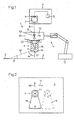
- is a schematic side view of an application device, partly in section, and
- Fig. 2
- a plan view of a nozzle arrangement when applying a material.
Fig. 1 zeigt schematisch eine Vorrichtung 1 zum Auftragen
eines Beschichtungsmaterials 2 (im folgenden kurz:
Material genannt) auf eine Oberfläche 3. Das Material 2
ist beim Auftrag flüssig. Es weist eine Viskosität im
Bereich von 250 bis 6000 mp auf und ist vorzugsweise
als wäßrige Dispersion ausgebildet. Wenn es trocknet,
bildet es eine Folie, die von der Oberfläche 3 abgezogen
werden kann.Fig. 1 shows schematically a device 1 for application
a coating material 2 (briefly in the following:
Called material) on a
Die Vorrichtung 1 weist eine Materialquelle 4 auf mit
einem Tank oder Vorratsbehälter 5 für das Material und
einer Dosiereinrichtung 6. Die Dosiereinrichtung 6
weist eine schematisch dargestellte Pumpe 7 auf. Die
Pumpe 7 ist vorzugsweise als Kolbenpumpe, als Schlauchpumpe
oder als Membranpumpe ausgebildet, so daß sie nur
geringe Scherkräfte auf das Material 2 ausübt, wenn sie
es von dem Vorratsbehälter 5 über eine Druckleitung 8
zu einer Düsenanordnung 9 pumpt.The device 1 has a material source 4 with
a tank or reservoir 5 for the material and
a metering device 6. The metering device 6
has a schematically illustrated
Die Düsenanordnung 9 ist an einem Träger 10 befestigt,
der einen Teil einer Transporteinrichtung 11 bildet.
Der Träger 10 kann aber auch als Hand-Werkzeug ausgebildet
sein, das ähnlich gehandhabt werden kann wie eine
Spritzpistole. Die Transporteinrichtung 11 weist einen
schematisch dargestellten Antrieb 12 auf, mit dem
der Träger 10 in Richtung eines Pfeils 13 bewegt werden
kann. Dieser Pfeil 13 stellt eine Arbeitsrichtung dar.
Selbstverständlich kann der Träger auch wieder in die
umgekehrte Richtung transportiert werden, um beispielsweise
eine Ausgangsstellung zu erreichen.The
Die Düsenanordnung 9, die in Fig. 1 im Schnitt dargestellt
ist, weist einen Korpus 14 auf. In dem Korpus 14
ist eine Austrittsöffnung 15 angeordnet. Diese Austrittsöffnung
15 ist als Vollstrahl-Austrittsöffnung
ausgebildet, d.h. Material, das über die Druckleitung 8
und einen Kanal 16 im Träger 10 zugeführt wird, kann
aus der Austrittsöffnung 15 in vollem Strahl austreten.
Der Strahl wird am Ende der Austrittsöffnung 15 nicht
zerstäubt, sondern er bleibt praktisch geschlossen.
Hierzu weist die Austrittsöffnung 15 einen relativ großen
Durchmesser im Bereich von 1,5 bis 4 mm auf.The
In der Druckleitung 8 oder im Kanal 16 kann ein schematisch
dargestelltes Ventil 22 vorgesehen sein, mit dem
der Austritt der Flüssigkeit aus der Düsenanordnung gesteuert
werden kann. Zweckmäßigerweise ist das Ventil
von außen, bei einem Hand-Werkzeug beispielsweise über
einen Betätigungshebel oder -knopf, oder sogar ferngesteuert
betätigbar.In the
Die Austrittsöffnung 15 ist auf eine Prallplatte 17 gerichtet,
die an der Düsenanordnung 9 ausgebildet ist.
Die Prallplatte 17 schließt mit der Achse der Austrittsöffnung
15 einen Winkel α im Bereich von 45° bis
85° ein. Die Prallplatte 17 bewirkt, daß die durch die
Austrittsöffnung 15 austretende Flüssigkeit sich zu einem
Flachstrahl 18, der gestrichelt gezeichnet ist,
ausbreitet. Der Flachstrahl 18 hat beim Auftreffen auf
die Oberfläche eine Breite b von mindestens 12 cm.The
Der Flachstrahl 18 ist so gerichtet, daß er mit der
Oberfläche 3 einen Winkel β im Bereich von 30° bis 90°
einschließt und zwar vorzugsweise entgegen der Bewegungsrichtung
(Pfeil 13), mit der die Düsenanordnung 9
über die Oberfläche 3 bewegt wird. Damit wird der
Flachstrahl 18 vereinfacht ausgedrückt über die Oberfläche
3 gezogen.The
Für den Auftrag des Materials 2 ist nur ein relativ
kleiner Druck notwendig. Der Druck am Eingang der Düsenanordnung
9 liegt in der Größenordnung von 2 bis
8 bar. Die Pumpe 7 muß über diesen Druck hinaus nur die
Druckverluste ausgleichen können, die in der Druckleitung
8 und im Träger 10 entstehen.Only one is relative for the application of
Die Austrittsöffnung 15 erweitert sich zum Träger 10
hin trichterförmig. Dies führt zu einer starken Beschleunigung
der Flüssigkeit beim Durchströmen der Düsenanordnung
9. Der Flachstrahl 18 erreicht damit die
gewünschte große Breite b. Er wird dafür relativ dünn,
so daß der Auftrag des Materials 2 auf der Oberfläche 3
mit einer relativ kleinen, dafür aber gleichmäßigen
Schichtdicke erfolgen kann.The
Die Prallplatte 17 ist zumindest an ihrem abgabeseitigen
Ende, wo der Flachstrahl 18 die Prallplatte 17 verläßt,
mit dem Winkel β zur Oberfläche 3 ausgerichtet.
Dies ergibt den gewünschten Winkel, den der Flachstrahl
18 mit der Oberfläche 3 einschließt. Die Prallplatte 17
weist an ihrem abgabeseitigen Ende einen Abstand im Bereich
von 3 bis 10 cm zur Oberfläche 3 auf. Dieser Abstand
erlaubt es einerseits, daß sich der Flachstrahl
18 in der gewünschten Weise seitlich ausbreitet. Der
Abstand ist andererseits noch kurz genug, so daß sich
der Flachstrahl 18 nicht in Einzelstrahlen oder
- tropfen aufteilt.The
Die Transporteinrichtung 11 kann auch durch einen Handhabungsautomaten
oder einen "Roboter" gebildet sein,
der nicht nur die Bewegung der Düsenanordnung 9 in die
Arbeitsrichtung (Pfeil 13) ermöglicht, sondern auch eine
Bewegung senkrecht dazu (Pfeil 19 in Fig. 2). Man
kann also die Düsenanordnung 9 seitlich versetzen, um
in einem zweiten Arbeitsgang einen zweiten Flachstrahl
18 auf die Oberfläche 3 zu richten, um einen weiteren
Streifen von Material 2 auf die Oberfläche 3 aufzutragen.The
Die Düsenanordnung 9 ist 20 am Träger 10 befestigt,
z.B. mit Hilfe einer Überwurfmutter. Die Düsenanordnung
9 kann eine Ausnehmung 21 aufweisen, in die ein entsprechender
Vorsprung am Träger 10 eingreift (nicht näher
dargestellt). Die Ausnehmung 21 bildet also in diesem
Fall eine'Ausrichthilfe, mit der die Düsenanordnung
9 grob am Träger 10 ausgerichtet werden kann, wenn die
Überwurfmutter 20 festgezogen wird. Trotz dieser Ausrichthilfe
ist es aber möglich, die Ausrichtung der Düsenanordnung
9 am Träger 10 in gewissen Grenzen zu verändern,
um die Lage des Flachstrahls 18 in Bezug auf
die Oberfläche 3 genauer einstellen zu können. Es ist
aber auch möglich, die Düsenanordnung von vornherein
fest ausgerichtet am Träger 10 zu befestigen.The
Wie aus Fig. 1 hervorgeht, ist der Antrieb 12 der
Transporteinrichtung 11 mit der Dosiereinrichtung 6 gekoppelt.
Die Dosiereinrichtung 6 arbeitet volumetrisch;
d.h. sie wird so gesteuert, daß der Volumenstrom des
Materials eine vorbestimmte Größe erhält. Dieser Volumenstrom
kann allerdings in Abhängigkeit von der Geschwindigkeit
eingestellt werden, mit der die Düsenanordnung
9 gegenüber der Oberfläche 3 bewegt wird. Damit
ist es möglich, immer eine gleichmäßige Dicke des Materials
2 auf der Oberfläche 3 zu erhalten.1, the
Die Transporteinrichtung 11 kann auch dreidimensional
arbeiten. Dies ist insbesondere dann von Vorteil, wenn
die Oberfläche 3 nicht, wie dargestellt, eben ist, sondern
ebenfalls dreidimensional ausgebildet ist. Dies
ist beispielsweise bei einem Kraftfahrzeug der Fall.The
Mit der Vorrichtung 1 läßt sich eine Flüssigfolie auf die Außenseite eines Kraftfahrzeugs auftragen. Nach dem Abtrocknen der Flüssigkeit bildet sich eine Folie, die in einem Stück oder jedenfalls mehreren größeren Stükken abgezogen werden kann, wenn das Fahrzeug an den Endverbraucher übergeben werden soll.With the device 1, a liquid film can be apply the outside of a motor vehicle. After this Drying the liquid forms a film that in one piece or in any case several larger pieces can be deducted when the vehicle to the End consumers should be handed over.
Claims (17)
Applications Claiming Priority (4)
| Application Number | Priority Date | Filing Date | Title |
|---|---|---|---|
| DE10241222 | 2002-09-06 | ||
| DE2002141222 DE10241222B4 (en) | 2002-09-06 | 2002-09-06 | Device for applying a liquid coating material, in particular a liquid film |
| DE20219052U DE20219052U1 (en) | 2002-09-06 | 2002-12-10 | Device for applying a liquid coating material, in particular a liquid film |
| DE20219052U | 2002-12-10 |
Publications (2)
| Publication Number | Publication Date |
|---|---|
| EP1396286A1 true EP1396286A1 (en) | 2004-03-10 |
| EP1396286B1 EP1396286B1 (en) | 2006-03-22 |
Family
ID=31716613
Family Applications (1)
| Application Number | Title | Priority Date | Filing Date |
|---|---|---|---|
| EP20030017491 Expired - Lifetime EP1396286B1 (en) | 2002-09-06 | 2003-08-02 | Arrangement for liquid coating, especially for a liquid film |
Country Status (2)
| Country | Link |
|---|---|
| EP (1) | EP1396286B1 (en) |
| DE (1) | DE50302715D1 (en) |
Cited By (1)
| Publication number | Priority date | Publication date | Assignee | Title |
|---|---|---|---|---|
| WO2011006853A1 (en) | 2009-07-13 | 2011-01-20 | Cambi As | Exchangeable nozzle device for pressure relief of materials containing erosive compounds |
Citations (5)
| Publication number | Priority date | Publication date | Assignee | Title |
|---|---|---|---|---|
| US3554164A (en) * | 1966-07-13 | 1971-01-12 | Binks Mfg Co | Powder spray system |
| US4102501A (en) * | 1976-12-16 | 1978-07-25 | The Leisure Group | Deflector assembly for a spray gun |
| US4828182A (en) * | 1984-04-19 | 1989-05-09 | Spraying Systems Co. | Spray nozzle assembly with recessed deflector |
| US5275340A (en) * | 1991-06-14 | 1994-01-04 | Spraying Systems Co. | Spray nozzle with recessed deflector surface |
| US6063450A (en) * | 1997-05-27 | 2000-05-16 | Voith Sulzer Papiermaschinen Gmbh | Method and apparatus for directly or indirectly applying a liquid pasty application medium to one or both sides of a continuous surface |
-
2003
- 2003-08-02 DE DE50302715T patent/DE50302715D1/en not_active Expired - Lifetime
- 2003-08-02 EP EP20030017491 patent/EP1396286B1/en not_active Expired - Lifetime
Patent Citations (5)
| Publication number | Priority date | Publication date | Assignee | Title |
|---|---|---|---|---|
| US3554164A (en) * | 1966-07-13 | 1971-01-12 | Binks Mfg Co | Powder spray system |
| US4102501A (en) * | 1976-12-16 | 1978-07-25 | The Leisure Group | Deflector assembly for a spray gun |
| US4828182A (en) * | 1984-04-19 | 1989-05-09 | Spraying Systems Co. | Spray nozzle assembly with recessed deflector |
| US5275340A (en) * | 1991-06-14 | 1994-01-04 | Spraying Systems Co. | Spray nozzle with recessed deflector surface |
| US6063450A (en) * | 1997-05-27 | 2000-05-16 | Voith Sulzer Papiermaschinen Gmbh | Method and apparatus for directly or indirectly applying a liquid pasty application medium to one or both sides of a continuous surface |
Cited By (1)
| Publication number | Priority date | Publication date | Assignee | Title |
|---|---|---|---|---|
| WO2011006853A1 (en) | 2009-07-13 | 2011-01-20 | Cambi As | Exchangeable nozzle device for pressure relief of materials containing erosive compounds |
Also Published As
| Publication number | Publication date |
|---|---|
| DE50302715D1 (en) | 2006-05-11 |
| EP1396286B1 (en) | 2006-03-22 |
Similar Documents
| Publication | Publication Date | Title |
|---|---|---|
| EP3718639B1 (en) | Coating device and corresponding operating method | |
| DE2657533C3 (en) | Spray device | |
| EP3576884B1 (en) | Application device for coating workpieces and coating device | |
| DE1009071B (en) | Gun for spraying at least two spray materials with an additional, exchangeable spray material container | |
| DE102007048651A1 (en) | Coating system for delivering flexible coating material on substrate, has control device actuated to supply chain of impulses to solenoid valve, needle valve closed for intervals between impulses, and coating material discharged from needle | |
| DE10059406A1 (en) | Spray device for paint spraying vehicles etc has first nozzle horns adjoining long sides of flat jet nozzle and two second nozzle horns adjoining narrow sides of same and each having air bores | |
| EP3184177A1 (en) | Air cap and nozzle assembly for a spray gun and spray gun | |
| DE19544016A1 (en) | Atomizing head for liquids and device for spraying workpieces with liquids with such atomizing heads | |
| DE4208500C2 (en) | Spray device for applying a liquid medium such as paint | |
| EP1442344B1 (en) | Method and device for treating objects by means of a liquid | |
| EP2248598B1 (en) | Device with multiple dry air nozzles and method for discharging an adhesive | |
| DE2815246A1 (en) | PAINT SPRAY GUN | |
| DE2048043C3 (en) | Spray device | |
| EP1396286B1 (en) | Arrangement for liquid coating, especially for a liquid film | |
| DE10241222B4 (en) | Device for applying a liquid coating material, in particular a liquid film | |
| DE4221155C1 (en) | ||
| DE1534429B2 (en) | Mobile device for creating traffic guidelines by means of paint application | |
| DE2530630C2 (en) | Process for the production of metal oxide layers on glass plates and device for carrying out the process | |
| WO2019043455A1 (en) | Device for spraying adhesive, and method | |
| EP0690175A1 (en) | Airless spray process for applying marking lines on roads and apparatus to carry out the process | |
| DE10129250A1 (en) | Fluid nozzle for application of broad fluid layer to component surface has spray gap defined by gap walls, one of which is moveable at right angles to the spray gap | |
| DE701222C (en) | Procedure for operating paint and spray guns | |
| EP1949969B1 (en) | Varnishing device | |
| DE19937135A1 (en) | Device to apply liquid onto roller of offset printing machine, with liquid discharged by compressed air through valve activated by piezoelectric translators | |
| EP4326448A1 (en) | Metering module |
Legal Events
| Date | Code | Title | Description |
|---|---|---|---|
| PUAI | Public reference made under article 153(3) epc to a published international application that has entered the european phase |
Free format text: ORIGINAL CODE: 0009012 |
|
| AK | Designated contracting states |
Kind code of ref document: A1 Designated state(s): AT BE BG CH CY CZ DE DK EE ES FI FR GB GR HU IE IT LI LU MC NL PT RO SE SI SK TR |
|
| AX | Request for extension of the european patent |
Extension state: AL LT LV MK |
|
| 17P | Request for examination filed |
Effective date: 20040827 |
|
| AKX | Designation fees paid |
Designated state(s): DE |
|
| 17Q | First examination report despatched |
Effective date: 20050308 |
|
| GRAP | Despatch of communication of intention to grant a patent |
Free format text: ORIGINAL CODE: EPIDOSNIGR1 |
|
| GRAS | Grant fee paid |
Free format text: ORIGINAL CODE: EPIDOSNIGR3 |
|
| GRAA | (expected) grant |
Free format text: ORIGINAL CODE: 0009210 |
|
| AK | Designated contracting states |
Kind code of ref document: B1 Designated state(s): DE |
|
| REF | Corresponds to: |
Ref document number: 50302715 Country of ref document: DE Date of ref document: 20060511 Kind code of ref document: P |
|
| PLBE | No opposition filed within time limit |
Free format text: ORIGINAL CODE: 0009261 |
|
| STAA | Information on the status of an ep patent application or granted ep patent |
Free format text: STATUS: NO OPPOSITION FILED WITHIN TIME LIMIT |
|
| 26N | No opposition filed |
Effective date: 20061227 |
|
| PGFP | Annual fee paid to national office [announced via postgrant information from national office to epo] |
Ref country code: DE Payment date: 20130814 Year of fee payment: 11 |
|
| REG | Reference to a national code |
Ref country code: DE Ref legal event code: R119 Ref document number: 50302715 Country of ref document: DE |
|
| REG | Reference to a national code |
Ref country code: DE Ref legal event code: R119 Ref document number: 50302715 Country of ref document: DE Effective date: 20150303 |
|
| PG25 | Lapsed in a contracting state [announced via postgrant information from national office to epo] |
Ref country code: DE Free format text: LAPSE BECAUSE OF NON-PAYMENT OF DUE FEES Effective date: 20150303 |