EP1396286A1 - Dispositif pour appliquer matière de revêtement liquide, spécialement une feuille liquide - Google Patents
Dispositif pour appliquer matière de revêtement liquide, spécialement une feuille liquide Download PDFInfo
- Publication number
- EP1396286A1 EP1396286A1 EP03017491A EP03017491A EP1396286A1 EP 1396286 A1 EP1396286 A1 EP 1396286A1 EP 03017491 A EP03017491 A EP 03017491A EP 03017491 A EP03017491 A EP 03017491A EP 1396286 A1 EP1396286 A1 EP 1396286A1
- Authority
- EP
- European Patent Office
- Prior art keywords
- nozzle arrangement
- range
- material source
- transport device
- liquid
- Prior art date
- Legal status (The legal status is an assumption and is not a legal conclusion. Google has not performed a legal analysis and makes no representation as to the accuracy of the status listed.)
- Granted
Links
- 239000007788 liquid Substances 0.000 title claims abstract description 27
- 239000011248 coating agent Substances 0.000 title claims abstract description 7
- 238000000576 coating method Methods 0.000 title claims abstract description 7
- 239000000463 material Substances 0.000 claims abstract description 50
- 239000006185 dispersion Substances 0.000 claims description 4
- 230000002572 peristaltic effect Effects 0.000 claims description 3
- 230000032258 transport Effects 0.000 description 21
- 239000007921 spray Substances 0.000 description 3
- 238000001035 drying Methods 0.000 description 2
- 239000010410 layer Substances 0.000 description 2
- 239000003973 paint Substances 0.000 description 2
- 239000011241 protective layer Substances 0.000 description 2
- 230000001133 acceleration Effects 0.000 description 1
- 230000015572 biosynthetic process Effects 0.000 description 1
- 238000005265 energy consumption Methods 0.000 description 1
- 230000007613 environmental effect Effects 0.000 description 1
- 238000003912 environmental pollution Methods 0.000 description 1
- 239000012535 impurity Substances 0.000 description 1
- 230000007257 malfunction Effects 0.000 description 1
- 238000005507 spraying Methods 0.000 description 1
- 230000008719 thickening Effects 0.000 description 1
Images
Classifications
-
- B—PERFORMING OPERATIONS; TRANSPORTING
- B05—SPRAYING OR ATOMISING IN GENERAL; APPLYING FLUENT MATERIALS TO SURFACES, IN GENERAL
- B05B—SPRAYING APPARATUS; ATOMISING APPARATUS; NOZZLES
- B05B1/00—Nozzles, spray heads or other outlets, with or without auxiliary devices such as valves, heating means
- B05B1/26—Nozzles, spray heads or other outlets, with or without auxiliary devices such as valves, heating means with means for mechanically breaking-up or deflecting the jet after discharge, e.g. with fixed deflectors; Breaking-up the discharged liquid or other fluent material by impinging jets
- B05B1/262—Nozzles, spray heads or other outlets, with or without auxiliary devices such as valves, heating means with means for mechanically breaking-up or deflecting the jet after discharge, e.g. with fixed deflectors; Breaking-up the discharged liquid or other fluent material by impinging jets with fixed deflectors
- B05B1/267—Nozzles, spray heads or other outlets, with or without auxiliary devices such as valves, heating means with means for mechanically breaking-up or deflecting the jet after discharge, e.g. with fixed deflectors; Breaking-up the discharged liquid or other fluent material by impinging jets with fixed deflectors the liquid or other fluent material being deflected in determined directions
Definitions
- the invention relates to a device for application a liquid coating material, in particular a liquid film, on a surface with a material source and a nozzle arrangement which has a Pressure line is connected to the material source and is movable relative to the surface.
- the invention is illustrated below using the example of application a liquid film written on a surface. In principle, however, it is also when applying other coating materials can be used.
- the film should be removed in one piece if possible can be done: This only works if the application of the liquid film under certain conditions is done. In particular, it is annoying when Drops, thickenings or other major inhomogeneities have formed. These then lead to removal the slide to malfunctions. The film tears at such Impurities so that residues stick to the surface remain that must be removed individually.
- the invention has for its object a surface with certain materials, especially one Liquid film to be able to coat without it Formation of larger inhomogeneities comes.
- This task is the beginning of a device mentioned type in that the nozzle arrangement has a full jet outlet opening, which against a baffle is aimed.
- the full jet outlet opening allows a liquid jet to massive exit. This makes a relative large discharge amount allows without a there is a greater risk that the beam will separate into individual beams divides or forms droplets. That beam but is not aimed directly at the surface, but first he hits a baffle.
- the baffle deflects the beam on the one hand and on the other hand spreads it out so that a wide beam arises, which has a relatively small thickness.
- This Flat jet can now be moved across the surface either by hand when the order setup is designed as a hand tool, e.g. in the manner of a spray gun, or by means of a transport device, e.g. a robot.
- the flat jet transports the material onto the surface in such a way that a relatively uniform job is done. The education of drops or single jets that later become disjointed Lots of the film could lead avoided.
- the baffle plate closes with the axis of the Outlet opening an angle in the range of 45 ° to 85 ° on.
- the flat jet is therefore deflected relatively strongly versus the direction the liquid is in the outlet opening. This leads to the desired one Spread of the flat jet.
- the flat jet is also correspondingly flat can be directed to the surface without the nozzle arrangement is excessive from the surface must incline.
- the baffle plate preferably connects at least its discharge end with the surface at an angle in the range from 30 ° to 90 °, preferably counter the direction of work. This angle essentially determines also the angle of incidence of the flat jet the surface.
- the flat jet is over the surface "pulled", i.e. the nozzle arrangement is located when applying the coating material over a uncoated area of the surface. It has emphasized that such alignment of the Flat jet shows the best results.
- the angle is preset when the nozzle arrangement on a Transport device is attached.
- the baffle plate is preferably at a distance from Surface in the range of 3 to 10 cm. This too can be set up when the nozzle arrangement on a transport device is attached, for example a handling machine: the path that the flat jet must travel in the air is therefore comparatively small.
- the flat jet on the other hand, has enough space to spread out, so that with a wide flat jet you can also get a larger one Can coat the surface relatively quickly.
- the nozzle arrangement creates a flat one Beam with a width of at least 8 cm. This allows a rational work.
- the outlet opening preferably has one Diameter in the range from 1.5 to 4 mm. This is a relatively large diameter. He allows you accordingly large throughput of the material. The danger, that the outlet opening is blocked is comparatively small.
- the material source preferably generates a pressure in the range of 2 to 8 bar at the inlet of the nozzle arrangement.
- the pressure the material source exits generated must of course be correspondingly larger, because the pressure losses in the pressure line are taken into account Need to become. Still, the pressure is the material source must produce, relatively small. This keeps the Low energy consumption and allows use more cost-effectively Conveying and dosing systems. In addition there is no danger that the flat jet due to a atomized to great pressure.
- the material source preferably has a volumetric one Dosing device on.
- the dosing device is therefore capable of a certain volume per unit of time to promote. This allowed more precise control as a control based on pressure only.
- the metering device is preferably provided with a transport device coupled and adjusts the volume flow of the material on the speed of the nozzle arrangement towards the surface. If the nozzle assembly lower speed compared to the surface then the volume flow becomes corresponding reduced. The volume flow is reversed enlarged when the nozzle arrangement is opposite the surface has a higher speed. The fat The material application can therefore be relatively uniform being held.
- Measures can also be taken in the manner of a spray gun provide to influence the volume flow, for example a changeable by a hand lever Valve opening.
- the metering device preferably has a pump on, the shear forces on the material below one predetermined limit, in particular a piston pump, a peristaltic pump or a diaphragm pump.
- the dosing device So it only affects the material low.
- the transport device preferably enables a multi-axis movement of the nozzle arrangement.
- the transport device preferably has one Automatic machines on.
- Such an automatic machine which is also referred to as a "robot” a fully automatic control of the movement of the nozzle arrangement and thus a fully automatic application of the Material on the surface.
- the material source preferably provides a liquid with a viscosity in the range of 250 to 6000 mp. In this viscosity range, the Applying a liquid film in particular gives good results.
- the material source is an aqueous one Dispersion delivers.
- the integral parts of Dispersion is then deposited on the surface.
- the liquid can evaporate or on others Way to be removed when the surface is dried becomes.
- the nozzle arrangement is preferably adjustable attached to the transport device. Then you are in the Location, the nozzle arrangement opposite the transport device to adjust. This is especially true of Advantage if several nozzle arrangements on a common Transport device or at different Transport devices are provided.
- the nozzle arrangement is preferably by means of a Union nut attached to the transport device. This allows a relatively simple adjustment.
- This alignment aid initially allows one rough presetting of the nozzle arrangement compared to the Transport means. It makes assembly easier. she but leaves enough game to the exact orientation of the Nozzle arrangement opposite the transport device to be able to change.
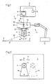
- Fig. 1 shows schematically a device 1 for application a coating material 2 (briefly in the following: Called material) on a surface 3.
- the material 2 is liquid when applied. It has a viscosity in the Range from 250 to 6000 mp and is preferred formed as an aqueous dispersion. When it dries it forms a film that is peeled off the surface 3 can be.
- the device 1 has a material source 4 with a tank or reservoir 5 for the material and a metering device 6.
- the metering device 6 has a schematically illustrated pump 7.
- the Pump 7 is preferably a piston pump, a peristaltic pump or designed as a diaphragm pump so that they only exerts low shear forces on the material 2 when it it from the reservoir 5 via a pressure line 8 pumps to a nozzle arrangement 9.
- the nozzle arrangement 9 is attached to a carrier 10, which forms part of a transport device 11.
- the carrier 10 can also be designed as a hand tool that can be handled similarly to one Spray gun.
- the transport device 11 has one schematically illustrated drive 12 with which the carrier 10 can be moved in the direction of an arrow 13 can. This arrow 13 represents a working direction. Of course, the wearer can also return to the reverse direction to be transported, for example to reach a starting position.
- the nozzle arrangement 9 shown in section in FIG. 1 has a body 14.
- an outlet opening 15 is arranged in the body 14 in the body 14 .
- This exit opening 15 is as a full jet outlet trained, i.e. Material via the pressure line 8 and a channel 16 in the carrier 10 can be supplied emerge in full jet from the outlet opening 15.
- the beam is not at the end of the outlet opening 15 atomized, but it remains practically closed.
- the outlet opening 15 has a relatively large one Diameter in the range from 1.5 to 4 mm.
- valve 22 may be provided with the controlled the exit of the liquid from the nozzle assembly can be.
- the valve is expedient from the outside, for example with a hand tool an operating lever or button, or even remotely controlled actuated.
- the outlet opening 15 is directed onto a baffle plate 17, which is formed on the nozzle arrangement 9.
- the baffle plate 17 closes with the axis of the outlet opening 15 an angle ⁇ in the range from 45 ° to 85 ° on.
- the baffle plate 17 causes that by the Exit opening 15 emerging liquid to a Flat jet 18, which is drawn in dashed lines, spreads.
- the flat jet 18 has on impact the surface has a width b of at least 12 cm.
- the flat jet 18 is directed so that it with the Surface 3 has an angle ⁇ in the range from 30 ° to 90 ° includes and preferably against the direction of movement (Arrow 13) with which the nozzle arrangement 9 is moved over the surface 3. With that the Flat jet 18, to put it simply, over the surface 3 pulled.
- the outlet opening 15 widens to the carrier 10 funnel-shaped. This leads to a strong acceleration the liquid as it flows through the nozzle arrangement 9.
- the flat jet 18 thus reaches the desired large width b. For this he becomes relatively thin, so that the application of the material 2 on the surface 3 with a relatively small but steady one Layer thickness can take place.
- the baffle plate 17 is at least on its discharge side End where the flat jet 18 leaves the baffle plate 17, aligned with the angle ⁇ to the surface 3. This gives the desired angle that the flat jet 18 with the surface 3 includes.
- the flapper 17 has a distance in the area at its discharge end from 3 to 10 cm to surface 3. This distance on the one hand, allows the flat jet 18 spreads out laterally in the desired manner. The On the other hand, distance is still short enough so that the flat jet 18 not in single jets or - split drops.
- the transport device 11 can also be operated by an automatic handling machine or a "robot", not only the movement of the nozzle assembly 9 in the Working direction (arrow 13) allows, but also a Movement perpendicular to it (arrow 19 in Fig. 2). you can thus move the nozzle arrangement 9 laterally to a second flat jet in a second operation 18 to the surface 3 to aim another Apply strips of material 2 to surface 3.
- an automatic handling machine or a "robot” not only the movement of the nozzle assembly 9 in the Working direction (arrow 13) allows, but also a Movement perpendicular to it (arrow 19 in Fig. 2). you can thus move the nozzle arrangement 9 laterally to a second flat jet in a second operation 18 to the surface 3 to aim another Apply strips of material 2 to surface 3.
- the nozzle arrangement 9 is fastened 20 to the carrier 10, e.g. with the help of a union nut.
- the nozzle arrangement 9 can have a recess 21 into which a corresponding one Projection engages the carrier 10 (not closer ) Shown.
- the recess 21 thus forms in this Case an alignment aid with which the nozzle arrangement 9 can be roughly aligned with the carrier 10 if the Union nut 20 is tightened.
- this alignment aid but it is possible to align the nozzle arrangement 9 to be changed on the carrier 10 within certain limits, to the location of the flat jet 18 with respect to to be able to adjust the surface 3 more precisely. It is but also possible, the nozzle arrangement from the outset to be firmly aligned on the carrier 10.
- the drive 12 is the Transport device 11 coupled to the metering device 6.
- the metering device 6 works volumetrically; i.e. it is controlled so that the volume flow of the Material receives a predetermined size. This volume flow can, however, depend on the speed with which the nozzle arrangement 9 is moved relative to the surface 3. In order to it is possible to always have an even thickness of material 2 to get on the surface 3.
- the transport device 11 can also be three-dimensional work. This is particularly advantageous if the surface 3 is not, as shown, flat, but is also three-dimensional. This is the case, for example, in a motor vehicle.
- a liquid film can be apply the outside of a motor vehicle. After this Drying the liquid forms a film that in one piece or in any case several larger pieces can be deducted when the vehicle to the End consumers should be handed over.
Landscapes
- Coating Apparatus (AREA)
Applications Claiming Priority (4)
| Application Number | Priority Date | Filing Date | Title |
|---|---|---|---|
| DE10241222 | 2002-09-06 | ||
| DE2002141222 DE10241222B4 (de) | 2002-09-06 | 2002-09-06 | Vorrichtung zum Auftragen eines flüssigen Beschichtungsmaterials, insbesondere einer Flüssigfolie |
| DE20219052U | 2002-12-10 | ||
| DE20219052U DE20219052U1 (de) | 2002-09-06 | 2002-12-10 | Vorrichtung zum Auftragen eines flüssigen Beschichtungsmaterials, insbesondere einer Flüssigfolie |
Publications (2)
| Publication Number | Publication Date |
|---|---|
| EP1396286A1 true EP1396286A1 (fr) | 2004-03-10 |
| EP1396286B1 EP1396286B1 (fr) | 2006-03-22 |
Family
ID=31716613
Family Applications (1)
| Application Number | Title | Priority Date | Filing Date |
|---|---|---|---|
| EP20030017491 Expired - Lifetime EP1396286B1 (fr) | 2002-09-06 | 2003-08-02 | Dispositif pour appliquer matière de revêtement liquide, spécialement une feuille liquide |
Country Status (2)
| Country | Link |
|---|---|
| EP (1) | EP1396286B1 (fr) |
| DE (1) | DE50302715D1 (fr) |
Cited By (1)
| Publication number | Priority date | Publication date | Assignee | Title |
|---|---|---|---|---|
| WO2011006853A1 (fr) | 2009-07-13 | 2011-01-20 | Cambi As | Dispositif de buse échangeable pour décompression de matériaux contenant des composés érosifs |
Citations (5)
| Publication number | Priority date | Publication date | Assignee | Title |
|---|---|---|---|---|
| US3554164A (en) * | 1966-07-13 | 1971-01-12 | Binks Mfg Co | Powder spray system |
| US4102501A (en) * | 1976-12-16 | 1978-07-25 | The Leisure Group | Deflector assembly for a spray gun |
| US4828182A (en) * | 1984-04-19 | 1989-05-09 | Spraying Systems Co. | Spray nozzle assembly with recessed deflector |
| US5275340A (en) * | 1991-06-14 | 1994-01-04 | Spraying Systems Co. | Spray nozzle with recessed deflector surface |
| US6063450A (en) * | 1997-05-27 | 2000-05-16 | Voith Sulzer Papiermaschinen Gmbh | Method and apparatus for directly or indirectly applying a liquid pasty application medium to one or both sides of a continuous surface |
-
2003
- 2003-08-02 EP EP20030017491 patent/EP1396286B1/fr not_active Expired - Lifetime
- 2003-08-02 DE DE50302715T patent/DE50302715D1/de not_active Expired - Lifetime
Patent Citations (5)
| Publication number | Priority date | Publication date | Assignee | Title |
|---|---|---|---|---|
| US3554164A (en) * | 1966-07-13 | 1971-01-12 | Binks Mfg Co | Powder spray system |
| US4102501A (en) * | 1976-12-16 | 1978-07-25 | The Leisure Group | Deflector assembly for a spray gun |
| US4828182A (en) * | 1984-04-19 | 1989-05-09 | Spraying Systems Co. | Spray nozzle assembly with recessed deflector |
| US5275340A (en) * | 1991-06-14 | 1994-01-04 | Spraying Systems Co. | Spray nozzle with recessed deflector surface |
| US6063450A (en) * | 1997-05-27 | 2000-05-16 | Voith Sulzer Papiermaschinen Gmbh | Method and apparatus for directly or indirectly applying a liquid pasty application medium to one or both sides of a continuous surface |
Cited By (1)
| Publication number | Priority date | Publication date | Assignee | Title |
|---|---|---|---|---|
| WO2011006853A1 (fr) | 2009-07-13 | 2011-01-20 | Cambi As | Dispositif de buse échangeable pour décompression de matériaux contenant des composés érosifs |
Also Published As
| Publication number | Publication date |
|---|---|
| EP1396286B1 (fr) | 2006-03-22 |
| DE50302715D1 (de) | 2006-05-11 |
Similar Documents
| Publication | Publication Date | Title |
|---|---|---|
| EP3718639B1 (fr) | Dispositif de revêtement et procédé de fonctionnement associé | |
| DE2657533C3 (de) | Sprühvorrichtung | |
| EP3576884B1 (fr) | Dispsitif d'application pour le revêtement de piéces et dispositif de revêtement | |
| DE102007048651A1 (de) | Beschichtungseinrichtung zur konformen Dünnlinien-Beschichtung sowie Verfahren dazu | |
| DE10059406A1 (de) | Spritzvorrichtung | |
| EP3184177A1 (fr) | Volet d'aération et système de buse pour un pistolet pulvérisateur et pistolet pulvérisateur | |
| DE102004049471A1 (de) | Vorrichtung zum Auftragen einer Konservierungsschicht und Verfahren zum Auftragen derselben | |
| DE4208500C2 (de) | Spritzvorrichtung zum Aufbringen eines flüssigen Mediums wie Farbe | |
| EP1442344B1 (fr) | Procede et dispositif pour traiter des objets a l'aide d'un liquide | |
| EP2248598B1 (fr) | Dispositif doté de plusieurs buses d'air sec et procédé de distribution de colle | |
| DE2815246A1 (de) | Lackspritzpistole | |
| DE2048043C3 (de) | Sprühvorrichtung | |
| EP1396286B1 (fr) | Dispositif pour appliquer matière de revêtement liquide, spécialement une feuille liquide | |
| DE10241222B4 (de) | Vorrichtung zum Auftragen eines flüssigen Beschichtungsmaterials, insbesondere einer Flüssigfolie | |
| DE3632269C2 (fr) | ||
| DE1534429C3 (fr) | ||
| DE4221155C1 (fr) | ||
| WO2019043455A1 (fr) | Dispositif pour la pulvérisation d'adhésif et procédé | |
| EP0690175A1 (fr) | Procédé de pulvérisation sans air pour la réalisation de lignes de signalisation et dispositif pour la mise en oeuvre du procédé | |
| DE10129250A1 (de) | Flüssigkeitsdüse zum breitflächigen Aufbringen einer Flüssigkeitsschicht auf eine Werkstückoberfläche sowie Verfahren zum Betreiben einer solchen | |
| DE701222C (de) | Verfahren zum Betriebe von Mal- und Spritzpistolen | |
| EP1949969B1 (fr) | Dispositif de laquage | |
| DE19937135A1 (de) | Sprühvorrichtung zum Auftragen von Feuchtmittel auf eine Feuchtwalze einer Offsetdruckmaschine | |
| EP4326448A1 (fr) | Module de dosage | |
| WO2002055214A1 (fr) | Dispositif pour enduire une piece allongee |
Legal Events
| Date | Code | Title | Description |
|---|---|---|---|
| PUAI | Public reference made under article 153(3) epc to a published international application that has entered the european phase |
Free format text: ORIGINAL CODE: 0009012 |
|
| AK | Designated contracting states |
Kind code of ref document: A1 Designated state(s): AT BE BG CH CY CZ DE DK EE ES FI FR GB GR HU IE IT LI LU MC NL PT RO SE SI SK TR |
|
| AX | Request for extension of the european patent |
Extension state: AL LT LV MK |
|
| 17P | Request for examination filed |
Effective date: 20040827 |
|
| AKX | Designation fees paid |
Designated state(s): DE |
|
| 17Q | First examination report despatched |
Effective date: 20050308 |
|
| GRAP | Despatch of communication of intention to grant a patent |
Free format text: ORIGINAL CODE: EPIDOSNIGR1 |
|
| GRAS | Grant fee paid |
Free format text: ORIGINAL CODE: EPIDOSNIGR3 |
|
| GRAA | (expected) grant |
Free format text: ORIGINAL CODE: 0009210 |
|
| AK | Designated contracting states |
Kind code of ref document: B1 Designated state(s): DE |
|
| REF | Corresponds to: |
Ref document number: 50302715 Country of ref document: DE Date of ref document: 20060511 Kind code of ref document: P |
|
| PLBE | No opposition filed within time limit |
Free format text: ORIGINAL CODE: 0009261 |
|
| STAA | Information on the status of an ep patent application or granted ep patent |
Free format text: STATUS: NO OPPOSITION FILED WITHIN TIME LIMIT |
|
| 26N | No opposition filed |
Effective date: 20061227 |
|
| PGFP | Annual fee paid to national office [announced via postgrant information from national office to epo] |
Ref country code: DE Payment date: 20130814 Year of fee payment: 11 |
|
| REG | Reference to a national code |
Ref country code: DE Ref legal event code: R119 Ref document number: 50302715 Country of ref document: DE |
|
| REG | Reference to a national code |
Ref country code: DE Ref legal event code: R119 Ref document number: 50302715 Country of ref document: DE Effective date: 20150303 |
|
| PG25 | Lapsed in a contracting state [announced via postgrant information from national office to epo] |
Ref country code: DE Free format text: LAPSE BECAUSE OF NON-PAYMENT OF DUE FEES Effective date: 20150303 |