EP3716416B1 - Elektrische kabelanordnung, verfahren und vorrichtung zu deren herstellung und elektrischer anschluss dafür - Google Patents
Elektrische kabelanordnung, verfahren und vorrichtung zu deren herstellung und elektrischer anschluss dafür Download PDFInfo
- Publication number
- EP3716416B1 EP3716416B1 EP20165520.6A EP20165520A EP3716416B1 EP 3716416 B1 EP3716416 B1 EP 3716416B1 EP 20165520 A EP20165520 A EP 20165520A EP 3716416 B1 EP3716416 B1 EP 3716416B1
- Authority
- EP
- European Patent Office
- Prior art keywords
- wire
- exposed
- terminal
- terminals
- wires
- Prior art date
- Legal status (The legal status is an assumption and is not a legal conclusion. Google has not performed a legal analysis and makes no representation as to the accuracy of the status listed.)
- Active
Links
Images




Classifications
-
- H—ELECTRICITY
- H01—ELECTRIC ELEMENTS
- H01R—ELECTRICALLY-CONDUCTIVE CONNECTIONS; STRUCTURAL ASSOCIATIONS OF A PLURALITY OF MUTUALLY-INSULATED ELECTRICAL CONNECTING ELEMENTS; COUPLING DEVICES; CURRENT COLLECTORS
- H01R12/00—Structural associations of a plurality of mutually-insulated electrical connecting elements, specially adapted for printed circuits, e.g. printed circuit boards [PCB], flat or ribbon cables, or like generally planar structures, e.g. terminal strips, terminal blocks; Coupling devices specially adapted for printed circuits, flat or ribbon cables, or like generally planar structures; Terminals specially adapted for contact with, or insertion into, printed circuits, flat or ribbon cables, or like generally planar structures
- H01R12/70—Coupling devices
- H01R12/77—Coupling devices for flexible printed circuits, flat or ribbon cables or like structures
- H01R12/771—Details
-
- B—PERFORMING OPERATIONS; TRANSPORTING
- B26—HAND CUTTING TOOLS; CUTTING; SEVERING
- B26D—CUTTING; DETAILS COMMON TO MACHINES FOR PERFORATING, PUNCHING, CUTTING-OUT, STAMPING-OUT OR SEVERING
- B26D3/00—Cutting work characterised by the nature of the cut made; Apparatus therefor
- B26D3/14—Forming notches in marginal portion of work by cutting
-
- H—ELECTRICITY
- H01—ELECTRIC ELEMENTS
- H01B—CABLES; CONDUCTORS; INSULATORS; SELECTION OF MATERIALS FOR THEIR CONDUCTIVE, INSULATING OR DIELECTRIC PROPERTIES
- H01B13/00—Apparatus or processes specially adapted for manufacturing conductors or cables
- H01B13/0036—Details
-
- H—ELECTRICITY
- H01—ELECTRIC ELEMENTS
- H01B—CABLES; CONDUCTORS; INSULATORS; SELECTION OF MATERIALS FOR THEIR CONDUCTIVE, INSULATING OR DIELECTRIC PROPERTIES
- H01B7/00—Insulated conductors or cables characterised by their form
- H01B7/08—Flat or ribbon cables
- H01B7/0823—Parallel wires, incorporated in a flat insulating profile
-
- H—ELECTRICITY
- H01—ELECTRIC ELEMENTS
- H01R—ELECTRICALLY-CONDUCTIVE CONNECTIONS; STRUCTURAL ASSOCIATIONS OF A PLURALITY OF MUTUALLY-INSULATED ELECTRICAL CONNECTING ELEMENTS; COUPLING DEVICES; CURRENT COLLECTORS
- H01R12/00—Structural associations of a plurality of mutually-insulated electrical connecting elements, specially adapted for printed circuits, e.g. printed circuit boards [PCB], flat or ribbon cables, or like generally planar structures, e.g. terminal strips, terminal blocks; Coupling devices specially adapted for printed circuits, flat or ribbon cables, or like generally planar structures; Terminals specially adapted for contact with, or insertion into, printed circuits, flat or ribbon cables, or like generally planar structures
- H01R12/50—Fixed connections
- H01R12/59—Fixed connections for flexible printed circuits, flat or ribbon cables or like structures
- H01R12/592—Fixed connections for flexible printed circuits, flat or ribbon cables or like structures connections to contact elements
-
- H—ELECTRICITY
- H01—ELECTRIC ELEMENTS
- H01R—ELECTRICALLY-CONDUCTIVE CONNECTIONS; STRUCTURAL ASSOCIATIONS OF A PLURALITY OF MUTUALLY-INSULATED ELECTRICAL CONNECTING ELEMENTS; COUPLING DEVICES; CURRENT COLLECTORS
- H01R12/00—Structural associations of a plurality of mutually-insulated electrical connecting elements, specially adapted for printed circuits, e.g. printed circuit boards [PCB], flat or ribbon cables, or like generally planar structures, e.g. terminal strips, terminal blocks; Coupling devices specially adapted for printed circuits, flat or ribbon cables, or like generally planar structures; Terminals specially adapted for contact with, or insertion into, printed circuits, flat or ribbon cables, or like generally planar structures
- H01R12/70—Coupling devices
- H01R12/77—Coupling devices for flexible printed circuits, flat or ribbon cables or like structures
- H01R12/778—Coupling parts carrying sockets, clips or analogous counter-contacts
-
- H—ELECTRICITY
- H01—ELECTRIC ELEMENTS
- H01R—ELECTRICALLY-CONDUCTIVE CONNECTIONS; STRUCTURAL ASSOCIATIONS OF A PLURALITY OF MUTUALLY-INSULATED ELECTRICAL CONNECTING ELEMENTS; COUPLING DEVICES; CURRENT COLLECTORS
- H01R13/00—Details of coupling devices of the kinds covered by groups H01R12/70 or H01R24/00 - H01R33/00
- H01R13/40—Securing contact members in or to a base or case; Insulating of contact members
- H01R13/42—Securing in a demountable manner
-
- H—ELECTRICITY
- H01—ELECTRIC ELEMENTS
- H01R—ELECTRICALLY-CONDUCTIVE CONNECTIONS; STRUCTURAL ASSOCIATIONS OF A PLURALITY OF MUTUALLY-INSULATED ELECTRICAL CONNECTING ELEMENTS; COUPLING DEVICES; CURRENT COLLECTORS
- H01R13/00—Details of coupling devices of the kinds covered by groups H01R12/70 or H01R24/00 - H01R33/00
- H01R13/40—Securing contact members in or to a base or case; Insulating of contact members
- H01R13/42—Securing in a demountable manner
- H01R13/424—Securing in base or case composed of a plurality of insulating parts having at least one resilient insulating part
-
- H—ELECTRICITY
- H01—ELECTRIC ELEMENTS
- H01R—ELECTRICALLY-CONDUCTIVE CONNECTIONS; STRUCTURAL ASSOCIATIONS OF A PLURALITY OF MUTUALLY-INSULATED ELECTRICAL CONNECTING ELEMENTS; COUPLING DEVICES; CURRENT COLLECTORS
- H01R13/00—Details of coupling devices of the kinds covered by groups H01R12/70 or H01R24/00 - H01R33/00
- H01R13/46—Bases; Cases
- H01R13/502—Bases; Cases composed of different pieces
-
- H—ELECTRICITY
- H01—ELECTRIC ELEMENTS
- H01R—ELECTRICALLY-CONDUCTIVE CONNECTIONS; STRUCTURAL ASSOCIATIONS OF A PLURALITY OF MUTUALLY-INSULATED ELECTRICAL CONNECTING ELEMENTS; COUPLING DEVICES; CURRENT COLLECTORS
- H01R4/00—Electrically-conductive connections between two or more conductive members in direct contact, i.e. touching one another; Means for effecting or maintaining such contact; Electrically-conductive connections having two or more spaced connecting locations for conductors and using contact members penetrating insulation
- H01R4/02—Soldered or welded connections
- H01R4/023—Soldered or welded connections between cables or wires and terminals
-
- H—ELECTRICITY
- H01—ELECTRIC ELEMENTS
- H01R—ELECTRICALLY-CONDUCTIVE CONNECTIONS; STRUCTURAL ASSOCIATIONS OF A PLURALITY OF MUTUALLY-INSULATED ELECTRICAL CONNECTING ELEMENTS; COUPLING DEVICES; CURRENT COLLECTORS
- H01R4/00—Electrically-conductive connections between two or more conductive members in direct contact, i.e. touching one another; Means for effecting or maintaining such contact; Electrically-conductive connections having two or more spaced connecting locations for conductors and using contact members penetrating insulation
- H01R4/24—Connections using contact members penetrating or cutting insulation or cable strands
- H01R4/2416—Connections using contact members penetrating or cutting insulation or cable strands the contact members having insulation-cutting edges, e.g. of tuning fork type
- H01R4/242—Connections using contact members penetrating or cutting insulation or cable strands the contact members having insulation-cutting edges, e.g. of tuning fork type the contact members being plates having a single slot
- H01R4/2425—Flat plates, e.g. multi-layered flat plates
- H01R4/2429—Flat plates, e.g. multi-layered flat plates mounted in an insulating base
-
- H—ELECTRICITY
- H01—ELECTRIC ELEMENTS
- H01R—ELECTRICALLY-CONDUCTIVE CONNECTIONS; STRUCTURAL ASSOCIATIONS OF A PLURALITY OF MUTUALLY-INSULATED ELECTRICAL CONNECTING ELEMENTS; COUPLING DEVICES; CURRENT COLLECTORS
- H01R43/00—Apparatus or processes specially adapted for manufacturing, assembling, maintaining, or repairing of line connectors or current collectors or for joining electric conductors
- H01R43/02—Apparatus or processes specially adapted for manufacturing, assembling, maintaining, or repairing of line connectors or current collectors or for joining electric conductors for soldered or welded connections
-
- H—ELECTRICITY
- H01—ELECTRIC ELEMENTS
- H01R—ELECTRICALLY-CONDUCTIVE CONNECTIONS; STRUCTURAL ASSOCIATIONS OF A PLURALITY OF MUTUALLY-INSULATED ELECTRICAL CONNECTING ELEMENTS; COUPLING DEVICES; CURRENT COLLECTORS
- H01R43/00—Apparatus or processes specially adapted for manufacturing, assembling, maintaining, or repairing of line connectors or current collectors or for joining electric conductors
- H01R43/02—Apparatus or processes specially adapted for manufacturing, assembling, maintaining, or repairing of line connectors or current collectors or for joining electric conductors for soldered or welded connections
- H01R43/0249—Apparatus or processes specially adapted for manufacturing, assembling, maintaining, or repairing of line connectors or current collectors or for joining electric conductors for soldered or welded connections for simultaneous welding or soldering of a plurality of wires to contact elements
-
- H—ELECTRICITY
- H01—ELECTRIC ELEMENTS
- H01R—ELECTRICALLY-CONDUCTIVE CONNECTIONS; STRUCTURAL ASSOCIATIONS OF A PLURALITY OF MUTUALLY-INSULATED ELECTRICAL CONNECTING ELEMENTS; COUPLING DEVICES; CURRENT COLLECTORS
- H01R43/00—Apparatus or processes specially adapted for manufacturing, assembling, maintaining, or repairing of line connectors or current collectors or for joining electric conductors
- H01R43/20—Apparatus or processes specially adapted for manufacturing, assembling, maintaining, or repairing of line connectors or current collectors or for joining electric conductors for assembling or disassembling contact members with insulating base, case or sleeve
-
- H—ELECTRICITY
- H01—ELECTRIC ELEMENTS
- H01R—ELECTRICALLY-CONDUCTIVE CONNECTIONS; STRUCTURAL ASSOCIATIONS OF A PLURALITY OF MUTUALLY-INSULATED ELECTRICAL CONNECTING ELEMENTS; COUPLING DEVICES; CURRENT COLLECTORS
- H01R43/00—Apparatus or processes specially adapted for manufacturing, assembling, maintaining, or repairing of line connectors or current collectors or for joining electric conductors
- H01R43/28—Apparatus or processes specially adapted for manufacturing, assembling, maintaining, or repairing of line connectors or current collectors or for joining electric conductors for wire processing before connecting to contact members, not provided for in groups H01R43/02 - H01R43/26
-
- H—ELECTRICITY
- H01—ELECTRIC ELEMENTS
- H01R—ELECTRICALLY-CONDUCTIVE CONNECTIONS; STRUCTURAL ASSOCIATIONS OF A PLURALITY OF MUTUALLY-INSULATED ELECTRICAL CONNECTING ELEMENTS; COUPLING DEVICES; CURRENT COLLECTORS
- H01R12/00—Structural associations of a plurality of mutually-insulated electrical connecting elements, specially adapted for printed circuits, e.g. printed circuit boards [PCB], flat or ribbon cables, or like generally planar structures, e.g. terminal strips, terminal blocks; Coupling devices specially adapted for printed circuits, flat or ribbon cables, or like generally planar structures; Terminals specially adapted for contact with, or insertion into, printed circuits, flat or ribbon cables, or like generally planar structures
- H01R12/50—Fixed connections
- H01R12/59—Fixed connections for flexible printed circuits, flat or ribbon cables or like structures
- H01R12/65—Fixed connections for flexible printed circuits, flat or ribbon cables or like structures characterised by the terminal
- H01R12/67—Fixed connections for flexible printed circuits, flat or ribbon cables or like structures characterised by the terminal insulation penetrating terminals
-
- H—ELECTRICITY
- H01—ELECTRIC ELEMENTS
- H01R—ELECTRICALLY-CONDUCTIVE CONNECTIONS; STRUCTURAL ASSOCIATIONS OF A PLURALITY OF MUTUALLY-INSULATED ELECTRICAL CONNECTING ELEMENTS; COUPLING DEVICES; CURRENT COLLECTORS
- H01R13/00—Details of coupling devices of the kinds covered by groups H01R12/70 or H01R24/00 - H01R33/00
- H01R13/46—Bases; Cases
- H01R13/514—Bases; Cases composed as a modular blocks or assembly, i.e. composed of co-operating parts provided with contact members or holding contact members between them
-
- H—ELECTRICITY
- H01—ELECTRIC ELEMENTS
- H01R—ELECTRICALLY-CONDUCTIVE CONNECTIONS; STRUCTURAL ASSOCIATIONS OF A PLURALITY OF MUTUALLY-INSULATED ELECTRICAL CONNECTING ELEMENTS; COUPLING DEVICES; CURRENT COLLECTORS
- H01R43/00—Apparatus or processes specially adapted for manufacturing, assembling, maintaining, or repairing of line connectors or current collectors or for joining electric conductors
- H01R43/02—Apparatus or processes specially adapted for manufacturing, assembling, maintaining, or repairing of line connectors or current collectors or for joining electric conductors for soldered or welded connections
- H01R43/0263—Apparatus or processes specially adapted for manufacturing, assembling, maintaining, or repairing of line connectors or current collectors or for joining electric conductors for soldered or welded connections for positioning or holding parts during soldering or welding process
Definitions
- the invention generally relates to a method of forming an electrical cable assembly and to the corresponding electrical cable assembly, particularly to a flat electrical cable assembly.
- Publication US 2002/020545 A1 discloses a method and an electrical cable assembly relating to the preamble of the independent claims 1 and 5, in which a flat cable is constituted by integrally forming a shield and an external sheath with a plurality of core wires. A slit for branching each of the core wires is then formed at a terminal of the flat cable. Further, a coupling portion is formed at a part in which the slit is formed. The coupling portion is a means for mechanically coupling the shield thereto. The coupling portion is constituted by an external sheath for riveting the shield thereto by penetrating the shield and then connecting the shield thereto.
- Publication US 2008/214065 A1 discloses a flexible flat cable having a conductor of a belt-shape and a covering portion for covering the conductor.
- the conductor has a groove along a longitudinal direction thereon, and is fixed in a terminal by placing on a bottom wall sandwiched between a pair of crimping pieces of the terminal and by crimping the pair of the crimping pieces.
- Publication JP 2002 231064 A discloses a method of separating the adjoining terminals of a flat cable in which terminals are installed along the longitudinal direction.
- Publication US 2016/099508 A1 discloses a connector that includes a lower housing, a plurality of first terminals fixed to the lower housing, a first flat cable connected to the first terminals, a first holder for holding the first flat cable, an upper housing assembled to the lower housing from above the first holder, a plurality of second terminals fixed to the upper housing, a second flat cable connected to the second terminals, and a second holder for holding the second flat cable.
- Each second terminal has a cable connection portion that comprises two clamping blades that stand upright in a longitudinal direction.
- Publication US 5 186 651 A discloses a plug member for a connector of the type in which the plug member is inserted into a coupler at an angle and then swung into its end position.
- the plug member has a sleeve portion guiding the cable as it is inserted so that the conductors of the cable pass into channels of a portion of the plug formed with windows through which the conductors are exposed and can be engaged by contacts of the coupler passing into these windows.
- Hooks can be provided in the sleeve portion. The hooks can engage in openings in the cable between conductors thereof.
- Publication US 2011/256764 A1 discloses a cable connector assembly that comprises: a plurality of first contacts, an insulative housing molding outside the first contacts, a plurality of second contacts received in the housing, a flat cable connecting with the first contacts and the second contacts, and the cable comprising a plurality of inner conductors arranged on upper and lower row, the upper row of the inner conductors soldered to the second contacts and the lower row of the inner conductors soldered to the first contacts, a metallic shell shielding outside the insulative housing.
- a method of forming an electrical cable assembly according to the present invention comprises the features of claim 1 of the application.
- a corresponding electrical cable assembly according to the present invention comprises the features of claim 5 of the application. Preferred embodiments are described in the dependent claims.
- an electrical cable assembly includes a multiconductor flat cable having a first electrically conductive wire and a second electrically conductive wire arranged in a coplanar fashion with each other.
- the first and second wires are encased within a planar dielectric structure.
- a slot is defined in the planar dielectric structure intermediate the first and second wires, thereby forming first wing features in the dielectric structure extending from the first wire and second wing features extending from the second wire. Exposed portions of the first and second wires extend beyond the first and second wing features.
- the electrical cable assembly has a housing formed of a dielectric material, a first electrical terminal and a second electrical both disposed within the housing.
- the exposed first wire is attached to the first terminal the exposed second wire is attached to the second terminal.
- the first and second terminals define prongs that are received within holes defined in portions of the first and second wing features, thereby retaining the first and seconds wires to the first and second terminals.
- the prongs are a pair of triangular prongs.
- the pair of triangular prongs are a pair of right triangular prongs.
- a first prong in the pair of right triangular prongs is arranged in reverse of a second prong in the pair of right triangular prongs.
- the second wire is shorter than the first wire.
- the first wire is bent such that it crosses over the second wire.
- the first terminal is laterally offset from the first wire within the connector.
- An example embodiment having one or more features of the electrical cable assembly of the previous paragraph includes a cover formed of dielectric material attached to the housing, thereby enclosing the first and second terminals.
- the first and second terminals each define a groove configured to receive the first and second wires and are sized to provide a friction fit between the first and second terminals and the first and second wires.
- the first and second wires are attached to the first and second terminals using a welding process.
- the first wire is bent such that the exposed first wire is aligned with the second exposed wire.
- the exposed second wire is attached to the electrical terminal.
- the exposed first wire is attached to the exposed second wire, thereby attaching the exposed first wire to the electrical terminal.
- the electrical terminal defines prongs.
- a portion of the second wing features is attached to the electrical terminal by inserting the prongs within holes defines in portions of the second wing features, thereby retaining the second wire to the electrical terminal.
- the portion of the first wing features are attached to the electrical terminal by inserting the prongs within the holes defined in portions of the first wing features, thereby retaining the first wire to the electrical terminal.
- the first and second wires have a substantially round cross section and wherein the first wire has a different cross sectional area than the second wire.
- a method of forming an electrical cable assembly includes the steps of providing a multiconductor flat cable comprising a first and second electrically conductive wire arranged in a coplanar fashion with each other and encased within a planar dielectric structure, cutting a slot in the planar dielectric structure intermediate the first and second wires, thereby forming first wing features in the dielectric structure extending from the first wire and second wing features extending from the second wire, and removing portions of the dielectric structure from ends of the first and second wires, thereby exposing portions of the first and second wires, wherein portions of the first and second wing features remain.
- the method includes the steps of providing a connector comprising a housing formed of a dielectric material, inserting first and second electrical terminals within the housing, and attaching the exposed first wire to the first terminal and attaching the exposed second wire to the second terminal.
- the first and second terminals define prongs and the method further includes the step of attaching the portions of the first and second wing features to the first and second terminals by inserting the prongs within holes defined in the portions of the first and second wing features, thereby retaining the first and seconds wires to the first and second terminals.
- the holes in the portions of the first and second wing features are formed by puncturing the portions of the first and second wing features using the prongs.
- An example embodiment having one or more features of the method of the previous paragraph includes the steps of cutting the second wire such that it is shorter than the first wire and bending an end potion of the first wire such that it crosses over the second wire.
- the first terminal is laterally offset from the first wire within the connector.
- An example embodiment having one or more features of the method of the previous paragraph includes the steps of providing a cover formed of dielectric material configured to attach to the housing and attaching the cover to the housing, thereby enclosing the first and second terminals.
- the first and second wires are attached to the first and second terminals using a welding process.
- An example embodiment having one or more features of the method of the previous paragraph includes the steps of providing a connector comprising a housing formed of a dielectric material, inserting an electrical terminal within the housing, attaching the exposed second wire to the first terminal, cutting the second wire such that it is shorter than the first wire, bending the first wire such that the exposed first wire is aligned with the second exposed wire, and attaching the exposed first wire to the exposed second wire, thereby attaching the exposed first wire to the electrical terminal.
- the electrical terminal defines prongs and the method further includes the steps of attaching a portion of the second wing features to the electrical terminal by inserting the prongs within holes defines in the portions of the second wing features, thereby retaining the second wire to the electrical terminal and attaching the portion of the first wing features to the electrical terminal by inserting the prongs within the holes defined in the portions of the first wing features, thereby retaining the first wire to the electrical terminal.
- an apparatus configured to manufacture an electrical cable assembly.
- the apparatus includes a transport mechanism configured to move a multiconductor flat cable, from a spool and through the apparatus.
- the flat cable includes first and second electrically conductive wires arranged in a coplanar fashion with each other and encased within a planar dielectric structure.
- the apparatus also includes a cutting mechanism configured to cut a slot in the planar dielectric structure intermediate the first and second wires, thereby forming first wing features in the dielectric structure extending from the first wire and second wing features extending from the second wire and a stripping mechanism configured to remove portions of the dielectric structure from ends of the first and second wires, thereby exposing portions of the first and second wires.
- the stripping mechanism is further configured to retain portions of the first and second wing features.
- the cutting mechanism is also configured to cut the second wire such that it is shorter than the first wire.
- the apparatus further comprises a bending mechanism that is configured to bend the third wire such that the exposed first wire is aligned with the second exposed wire or bend the first wire such that it crosses over the second wire.
- an electrical terminal in yet one more embodiment which does not form part of the invention as claimed, includes a connection portion configured to interconnect with a corresponding mating terminal, a wire attachment portion configured to receive a wire cable, and an insulation attachment portion defining a pair of triangular prongs arranged so as to receive the wire cable between the pair of triangular prongs, wherein the pair of triangular prongs are configured to puncture through a dielectric structure surrounding the wire cable and create holes in the dielectric structure in which the pair of triangular prongs are received.
- the electrical terminal defines a groove in which the wire cable is received, The groove is sized to provide a friction fit between the electrical terminal and the wire cable.
- the pair of triangular prongs is a pair of right triangular prongs.
- a first prong in the pair of triangular prongs is arranged in reverse of a second prong in the pair of right triangular prongs.
- reference numbers without letter suffixes may generically refer to a feature while reference numbers with suffixes may refer to specific features.
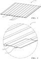
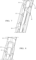
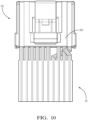
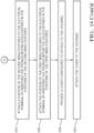
- Figs. 1-12 illustrate a non-limiting example of an electrical cable assembly 10 according to one or more embodiments of the invention.
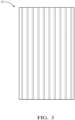
- the electrical cable assembly 10 includes a multiconductor flat cable 12, shown in Figs. 1-3 , having a plurality of electrically conductive wires 14 arranged in a coplanar fashion and generally parallel to one another.
- the wires 14 are encased within a planar insulative structure 16 formed of a dielectric material, such as polyethylene (PE), polytetrafluoroethylene (PTFE), or perfluoroalkoxy alkane (PFA).
- PE polyethylene
- PTFE polytetrafluoroethylene
- PFA perfluoroalkoxy alkane
- the planar insulative structure 16 may be formed using an extrusion process or may be formed by two separate insulative sheets that are attached to one another by an adhesive layer.
- the wires 14 have a round cross section and each of the wires 14 has the same diameter.
- Alternative embodiments may be envisioned in which at least one of the wires has a different diameter than the rest.
- Yet other alternative embodiments may be envisioned in which the wires have a square or rectangular cross section.
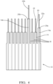
- slots 18 are cut in the planar insulative structure 16 between the wires 14 in an end section of the flat cable 12, thereby forming generally flat wing shaped features, hereinafter referred to as insulation wings 20, that extend from both sides of each wire 14.
- the remaining insulative structure 16 is totally removed, or stripped, from the distal ends of the wire 14, thereby providing exposed wire portions 22 extending beyond the insulation wings 20.
- some of the wires 14 may be cut to a different length than other wires 14.
- the slots 18 and wires 14 may be cut by a blade cutter, a blanking cutter, or a laser cutter. The preceding list of cutting means is neither limiting nor exclusive.
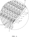
- the exposed wire portion 22a is disposed within the groove 38 of the terminal 30b and the exposed wire portion 22a is welded to the exposed wire portion 22, thereby forming a dual connection between the wires 14a, 14 and the terminal 30b.
- another wire 14b is bent such that is crosses over the wires 14, 14a and is attached to a terminal 30a that is longitudinally aligned with the wire 14a.
- the illustrated connection scheme provides the benefit of changing the circuit arrangement between ends of the cables, thereby allowing the same connector arrangement to accommodate different circuit configurations.
- the illustrated connection scheme is not limiting and other embodiments with different circuit arrangements may be envisioned.
Landscapes
- Engineering & Computer Science (AREA)
- Manufacturing & Machinery (AREA)
- Life Sciences & Earth Sciences (AREA)
- Forests & Forestry (AREA)
- Mechanical Engineering (AREA)
- Multi-Conductor Connections (AREA)
- Coupling Device And Connection With Printed Circuit (AREA)
- Insulated Conductors (AREA)
- Connections By Means Of Piercing Elements, Nuts, Or Screws (AREA)
Claims (7)
- Verfahren (200) zur Herstellung einer elektrischen Kabelanordnung (10), das die folgenden Schritte umfasst:Bereitstellen (202) eines Mehrleiter-Flachkabels (12), das einen ersten und einen zweiten elektrisch leitenden Draht (14) umfasst, die in einer koplanaren Anordnung zueinander stehen und in eine planare dielektrische Struktur (16) eingekapselt sind;Schneiden (204) eines Schlitzes (18) in der planaren dielektrischen Struktur (16) zwischen dem ersten und dem zweiten Draht (14), wodurch erste Flügelmerkmale (20) in der dielektrischen Struktur (16), die sich von dem ersten Draht (14) aus erstrecken, und zweite Flügelmerkmale (20), die sich von dem zweiten Draht (14) aus erstrecken, gebildet werden;Entfernen (206) von Abschnitten der dielektrischen Struktur (16) an den Enden des ersten und zweiten Drahts (14), wodurch Abschnitte des ersten und zweiten Drahts (14) freigelegt werden, wobei Abschnitte der ersten und zweiten Flügelmerkmale (20) erhalten bleiben;Bereitstellen (208) eines Verbinders (24) mit einem Gehäuse (26), das aus einem dielektrischen Material gebildet ist; und Einsetzen (210) eines ersten und eines zweiten elektrischen Anschlusses (30) in das Gehäuse (26);Befestigen (216) des freigelegten ersten Drahts (14) am ersten Anschluss (30) und des freigelegten zweiten Drahts (14) am zweiten Anschluss (30);wobei der erste und zweite Anschluss (30) einen Verbindungsabschnitt (34), der so konfiguriert ist, dass er mit einem entsprechenden Gegenstecker verbunden werden kann, und einen Befestigungsabschnitt (36), der so konfiguriert ist, dass der Anschluss (30) an dem Draht (14) befestigt werden kann, aufweisen und dadurch gekennzeichnet, dass der erste und zweite Anschluss (30) ein Paar von Gabelzinken (42) mit rechtwinkliger Dreiecksform definieren, wobei ein erster Zinken (42a) in dem Paar von Gabelzinken (42) mit rechtwinkliger Dreiecksform umgekehrt zu einem zweiten Zinken (42b) in dem Paar von Gabelzinken (42) mit rechtwinkliger Dreiecksform angeordnet ist, wobei eine Rückwärtsbewegung der ersten und zweiten Flügelmerkmale (20) durch eine vordere vertikale Oberfläche (46) des ersten Zinkens (42a) und die Vorwärtsbewegung der ersten und zweiten Flügelmerkmale (20) (20) durch eine hintere vertikale Oberfläche (48) des zweiten Zinkens (42b) begrenzt wird, wobei 'vorwärts' eine Position näher am Verbindungsabschnitt (34) und 'rückwärts' eine Position weiter vom Verbindungsabschnitt (34) weg bedeutet;wobei das Verfahren ferner den folgenden Schritt umfasst:
Anbringen (218) der Abschnitte der ersten und zweiten Flügelmerkmale (20) an dem ersten und zweiten Anschluss (30), indem die Zinken (42) in Löcher (44) eingeführt werden, die in den Abschnitten der ersten und zweiten Flügelmerkmale (20) definiert sind, wodurch der erste und zweite Draht (14) an dem ersten und zweiten Anschluss (30) befestigt werden. - Verfahren (200) nach Anspruch 1, ferner umfassend die folgenden Schritte:Schneiden (212) des zweiten Drahts (14) so, dass dieser kürzer als der erste Draht (14) ist; undBiegen (214) eines Endabschnitts des ersten Drahts (14) so, dass er den zweiten Draht (14) kreuzt, wobei der erste Anschluss (30) zu dem ersten Draht (14) innerhalb des Verbinders (24) seitlich versetzt ist.
- Verfahren (200) nach einem der vorhergehenden Ansprüche, ferner umfassend die folgenden Schritte:Bereitstellen (228) einer Abdeckung (50), die aus einem dielektrischen Material hergestellt ist und zur Befestigung am Gehäuse (26) konfiguriert ist; undAnbringen (230) der Abdeckung (50) am Gehäuse (26), wodurch der erste und zweite Anschluss (30) eingeschlossen werden.
- Verfahren (200) nach einem der vorhergehenden Ansprüche, ferner umfassend die folgenden Schritte:Schneiden (212) des zweiten Drahts (14) so, dass dieser kürzer als der erste Draht (14) ist;Biegen (220) des ersten Drahts (14) so, dass der freigelegte erste Draht (14) mit dem freigelegten zweiten Draht (14) fluchtet; undAnbringen (222) des freigelegten ersten Drahts (14) an dem freigelegten zweiten Draht (14), wodurch der freigelegte erste Draht (14) mit dem elektrischen Anschluss (30) verbunden wird.
- Elektrische Kabelanordnung (10), umfassend:ein Mehrleiter-Flachkabel (12) mit einem ersten und einem zweiten elektrisch leitenden Draht (14), die koplanar zueinander angeordnet und in einer planaren dielektrischen Struktur (16) eingeschlossen sind, wobei ein Schlitz (18) in der dielektrischen Struktur (16) zwischen dem ersten und dem zweiten Draht (14) definiert ist, wodurch erste Flügelmerkmale (20) in der dielektrischen Struktur (16), die sich von dem ersten Draht (14) aus erstrecken, und zweite Flügelmerkmale (20), die sich von dem zweiten Draht (14) aus erstrecken, gebildet werden, und wobei freiliegende Abschnitte des ersten und zweiten Drahts (14) über die ersten und zweiten Flügelmerkmale (20) hinausragen;ein Verbinder (24) mit einem Gehäuse (26), das aus einem dielektrischen Material gebildet ist; undeinen ersten und zweiten elektrischen Anschluss (30), die im Gehäuse (26) angeordnet sind, wobei der freiliegende erste Draht (14) an dem ersten Anschluss (30) und der freiliegende zweite Draht (14) an dem zweiten Anschluss (30) befestigt ist,wobei der erste und zweite Anschluss (30) einen Verbindungsabschnitt (34), der zur Verbindung mit einem entsprechenden Gegenstecker konfiguriert ist, und einen Befestigungsabschnitt (36), der zur Befestigung des Anschlusses (30) an dem Draht (14) konfiguriert ist, aufweisen, dadurch gekennzeichnet, dass der erste und zweite Anschluss (30) ein Paar von Zinken (42) mit rechtwinkliger Dreiecksform definieren, wobei ein erster Zinken (42a) in dem Paar von Gabelzinken (42) mit rechtwinkliger Dreiecksform umgekehrt zu einem zweiten Zinken (42b) in dem Paar von Gabelzinken (42) mit rechtwinkliger Dreiecksform angeordnet ist, wobei eine Rückwärtsbewegung der ersten und zweiten Flügelmerkmale (20) durch eine vordere vertikale Oberfläche (46) des ersten Zinkens (42a) und die Vorwärtsbewegung durch eine hintere vertikale Oberfläche (48) des zweiten Zinkens (42b) begrenzt wird, und wobei 'vorwärts' eine Position näher am Verbindungsabschnitt (34) und 'rückwärts' eine Position weiter vom Verbindungsabschnitt (34) anzeigt, und wobei die Zinken (42) so konfiguriert sind, dass sie in Löchern (44) aufgenommen werden, die in den Abschnitten der ersten und zweiten Flügelmerkmale (20) definiert sind, wodurch der erste und zweite Draht (14) an dem ersten und zweiten Anschluss (30) gehalten werden.
- Elektrische Kabelanordnung (10) nach Anspruch 5, wobei der zweite Draht (14) kürzer als der erste Draht (14) ist, wobei der erste Draht (14) so gebogen ist, dass er den zweiten Draht (14) kreuzt, und wobei der erste Anschluss (30) zu dem ersten Draht (14) innerhalb des Verbinders (24) seitlich versetzt ist.
- Elektrische Kabelanordnung (10) nach Anspruch 5, wobei der erste Draht (14) so gebogen ist, dass der freiliegende erste Draht (14) mit dem zweiten freiliegenden Draht (14) fluchtet; wobei der freiliegende zweite Draht (14) an dem elektrischen Anschluss (30) befestigt ist und wobei der freiliegende erste Draht (14) an dem freiliegenden zweiten Draht (14) befestigt ist, wodurch der freiliegende erste Draht (14) mit dem elektrischen Anschluss (30) verbunden wird.
Applications Claiming Priority (1)
| Application Number | Priority Date | Filing Date | Title |
|---|---|---|---|
| US16/363,235 US11069994B2 (en) | 2019-03-25 | 2019-03-25 | Electrical cable assembly, method and apparatus for making same and electrical terminal for same |
Publications (2)
| Publication Number | Publication Date |
|---|---|
| EP3716416A1 EP3716416A1 (de) | 2020-09-30 |
| EP3716416B1 true EP3716416B1 (de) | 2025-04-23 |
Family
ID=70008287
Family Applications (1)
| Application Number | Title | Priority Date | Filing Date |
|---|---|---|---|
| EP20165520.6A Active EP3716416B1 (de) | 2019-03-25 | 2020-03-25 | Elektrische kabelanordnung, verfahren und vorrichtung zu deren herstellung und elektrischer anschluss dafür |
Country Status (3)
| Country | Link |
|---|---|
| US (2) | US11069994B2 (de) |
| EP (1) | EP3716416B1 (de) |
| CN (1) | CN111740254A (de) |
Cited By (1)
| Publication number | Priority date | Publication date | Assignee | Title |
|---|---|---|---|---|
| US20240109732A1 (en) * | 2022-10-04 | 2024-04-04 | Komax Holding Ag | Machine network and method for arranging cables according to a specified cable sequence |
Families Citing this family (8)
| Publication number | Priority date | Publication date | Assignee | Title |
|---|---|---|---|---|
| JP2020068168A (ja) * | 2018-10-26 | 2020-04-30 | 株式会社オートネットワーク技術研究所 | コネクタ |
| JP7125653B2 (ja) * | 2018-10-30 | 2022-08-25 | 株式会社オートネットワーク技術研究所 | コネクタ |
| US11069994B2 (en) * | 2019-03-25 | 2021-07-20 | Aptiv Technologies Limited | Electrical cable assembly, method and apparatus for making same and electrical terminal for same |
| JP7476824B2 (ja) * | 2021-03-08 | 2024-05-01 | 株式会社オートネットワーク技術研究所 | コネクタ |
| CN113078529B (zh) * | 2021-03-25 | 2022-05-13 | 中航光电科技股份有限公司 | 一种高速背板连接器自动化焊接结构 |
| US20240079803A1 (en) * | 2022-09-02 | 2024-03-07 | Aptiv Technologies (2) S.À R.L. | Flat cable connector |
| US12347983B2 (en) | 2022-11-30 | 2025-07-01 | Lear Corporation | Connector for an electrical terminal with a crimped spring |
| US12580334B2 (en) * | 2023-11-09 | 2026-03-17 | Te Connectivity Solutions Gmbh | Front load connector system for flat flexible cables |
Citations (3)
| Publication number | Priority date | Publication date | Assignee | Title |
|---|---|---|---|---|
| US5186651A (en) * | 1991-01-29 | 1993-02-16 | Firma Karl Lumberg Gmbh & Co. | Plug connector, especially for the releasable connection of electrical conductors |
| US20110256764A1 (en) * | 2010-04-19 | 2011-10-20 | Hon Hai Precision Industry Co., Ltd. | Low profile cable connector assembly |
| US20160099508A1 (en) * | 2013-06-14 | 2016-04-07 | Yazaki Corporation | Flat-cable connection structure |
Family Cites Families (28)
| Publication number | Priority date | Publication date | Assignee | Title |
|---|---|---|---|---|
| US4125311A (en) * | 1975-12-15 | 1978-11-14 | Bunker Ramo Corporation | Insulation-piercing contact member and connector |
| US4130332A (en) | 1978-03-24 | 1978-12-19 | Amp Incorporated | Modular connector and crimp arrangement for magnetic wire |
| US4371225A (en) * | 1980-07-31 | 1983-02-01 | Thomas & Betts Corporation | Electrical connector for terminating flat multiconductor cable |
| US4350404A (en) * | 1980-09-24 | 1982-09-21 | Bell Telephone Laboratories, Incorporated | Electrical connector construction |
| US4690478A (en) * | 1986-04-10 | 1987-09-01 | United Technologies Automotive, Inc. | Sealed electrical connector assembly |
| JPH0754720B2 (ja) * | 1987-04-10 | 1995-06-07 | フレキシブルプリント回路板用電気接続端子 | |
| US5195908A (en) * | 1988-06-30 | 1993-03-23 | Sumitomo Wiring Systems, Ltd. | Multicircuit cable connector |
| US5078617A (en) * | 1991-01-25 | 1992-01-07 | Molex Incorporated | Piercing insulation displacement board terminal |
| US5314361A (en) * | 1991-05-02 | 1994-05-24 | The Whitaker Corporation | Electrical contact with recessed wire connecting portion |
| GB9425107D0 (en) * | 1994-12-13 | 1995-02-08 | Amp Gmbh | IDC branch connector for large range of wire sizes |
| DE59813527D1 (de) * | 1997-09-25 | 2006-06-08 | Tyco Electronics Logistics Ag | Anschlussorgan für elektrische Leitungen |
| JP2001143538A (ja) * | 1999-08-31 | 2001-05-25 | Auto Network Gijutsu Kenkyusho:Kk | シールドフラット電線並びにその製造方法および加工装置 |
| FR2800520B1 (fr) | 1999-10-28 | 2001-12-14 | Fci Automotive France | Perfectionnement aux dispositifs de connexion pour circuit souple |
| US6280241B2 (en) | 1999-12-13 | 2001-08-28 | Delphi Technologies, Inc. | Flat cable drop connection system |
| US6232556B1 (en) | 2000-02-23 | 2001-05-15 | Delphi Technologies, Inc. | Flat wire to round wire connection system |
| US6688920B2 (en) | 2001-01-23 | 2004-02-10 | Tyco Electronics Amp Gmbh | Connector assembly |
| JP2002231064A (ja) * | 2001-02-01 | 2002-08-16 | Auto Network Gijutsu Kenkyusho:Kk | フラットケーブルとそのスリットの形成方法 |
| US6686544B2 (en) | 2001-04-25 | 2004-02-03 | Autonetworks Technologies, Ltd. | Wiring material and method for manufacturing the same |
| US6705893B1 (en) * | 2002-09-04 | 2004-03-16 | Hon Hai Precision Ind. Co., Ltd. | Low profile cable connector assembly with multi-pitch contacts |
| JP4568210B2 (ja) * | 2005-11-14 | 2010-10-27 | 矢崎総業株式会社 | 端子金具及び端子付きフラット回路体 |
| JP4520933B2 (ja) * | 2005-11-18 | 2010-08-11 | 矢崎総業株式会社 | 端子連鎖体、該端子連鎖体を圧着するクリンパ、端子連鎖体の製造方法、及び複数の端子金具とフラット回路体の接続構造 |
| JP4500254B2 (ja) | 2005-12-26 | 2010-07-14 | 矢崎総業株式会社 | フラット回路体 |
| CN201797096U (zh) * | 2010-04-19 | 2011-04-13 | 富士康(昆山)电脑接插件有限公司 | 线缆连接器组件 |
| KR20140140195A (ko) * | 2013-05-28 | 2014-12-09 | 주식회사 유라코퍼레이션 | 케이블 조립체 및 그 제조 방법 |
| US10153570B2 (en) | 2017-04-14 | 2018-12-11 | Cellink Corporation | Flexible circuits for electrical harnesses |
| DE102018207794A1 (de) * | 2018-05-17 | 2019-11-21 | Te Connectivity Germany Gmbh | Flachbandkabelstecker, Steckeranordnung und Verwendung eines Steckers |
| US11069994B2 (en) * | 2019-03-25 | 2021-07-20 | Aptiv Technologies Limited | Electrical cable assembly, method and apparatus for making same and electrical terminal for same |
| US11600937B2 (en) * | 2020-07-02 | 2023-03-07 | Te Connectivity Solutions Gmbh | Electrical terminal for flat flexible cables |
-
2019
- 2019-03-25 US US16/363,235 patent/US11069994B2/en active Active
-
2020
- 2020-03-24 CN CN202010212787.3A patent/CN111740254A/zh active Pending
- 2020-03-25 EP EP20165520.6A patent/EP3716416B1/de active Active
-
2021
- 2021-06-15 US US17/347,804 patent/US11784426B2/en active Active
Patent Citations (3)
| Publication number | Priority date | Publication date | Assignee | Title |
|---|---|---|---|---|
| US5186651A (en) * | 1991-01-29 | 1993-02-16 | Firma Karl Lumberg Gmbh & Co. | Plug connector, especially for the releasable connection of electrical conductors |
| US20110256764A1 (en) * | 2010-04-19 | 2011-10-20 | Hon Hai Precision Industry Co., Ltd. | Low profile cable connector assembly |
| US20160099508A1 (en) * | 2013-06-14 | 2016-04-07 | Yazaki Corporation | Flat-cable connection structure |
Cited By (2)
| Publication number | Priority date | Publication date | Assignee | Title |
|---|---|---|---|---|
| US20240109732A1 (en) * | 2022-10-04 | 2024-04-04 | Komax Holding Ag | Machine network and method for arranging cables according to a specified cable sequence |
| US12577062B2 (en) * | 2022-10-04 | 2026-03-17 | Komax Holding Ag | Machine network and method for arranging cables according to a specified cable sequence |
Also Published As
| Publication number | Publication date |
|---|---|
| US20210313723A1 (en) | 2021-10-07 |
| US11784426B2 (en) | 2023-10-10 |
| EP3716416A1 (de) | 2020-09-30 |
| CN111740254A (zh) | 2020-10-02 |
| US11069994B2 (en) | 2021-07-20 |
| US20200313326A1 (en) | 2020-10-01 |
Similar Documents
| Publication | Publication Date | Title |
|---|---|---|
| US11784426B2 (en) | Electrical cable assembly, method and apparatus for making same and electrical terminal for same | |
| JP2617153B2 (ja) | 同軸ケーブルコネクター | |
| US8721376B1 (en) | Single element wire to board connector | |
| EP2700128B1 (de) | Anschlussstück | |
| CN105284006B (zh) | 扁平电缆连接结构 | |
| KR20100129739A (ko) | 후프 부재, 내부 전도체 터미널 및 동축 커넥터 제조 방법 | |
| JP4274381B2 (ja) | 極細同軸ケーブルの端末接続方法 | |
| JP4536378B2 (ja) | 同軸ケーブルコネクタ、同軸ケーブルへのコネクタの取付方法、及び同軸ケーブル圧接コンタクト | |
| JP4082710B2 (ja) | コネクタ | |
| KR20130069590A (ko) | 전기 커넥터를 위한 케이블 오거나이저 | |
| JPH04337262A (ja) | 絶縁穿孔導電端子 | |
| US7228625B1 (en) | Method for attaching an electrical cable to a connector shield | |
| JP5390792B2 (ja) | 接続部材 | |
| JPH087968A (ja) | コネクタ及びその組立方法 | |
| JP5765402B2 (ja) | 電気コネクタ | |
| KR101521386B1 (ko) | 케이블 접속 방법 | |
| US6149460A (en) | RF plug connection system and method for assembling the RF plug connection system | |
| KR101017045B1 (ko) | 동축 케이블용 피어싱 단자 | |
| US4266843A (en) | Insulation displacing electrical contact and method of making same | |
| EP0570832A1 (de) | Verbindergehäuseanordnung für einzelne Drähte | |
| JP6077775B2 (ja) | 電線と端子の接続構造 | |
| JPH11162529A (ja) | Hfプラグコネクタ系及び該hfプラグコネクタの組立法 | |
| JPH0817546A (ja) | フラットケーブル用コネクタの組立方法 | |
| JP2015002047A (ja) | フラットケーブルの接続構造 | |
| JP3127392B2 (ja) | ケーブルコネクタ |
Legal Events
| Date | Code | Title | Description |
|---|---|---|---|
| PUAI | Public reference made under article 153(3) epc to a published international application that has entered the european phase |
Free format text: ORIGINAL CODE: 0009012 |
|
| STAA | Information on the status of an ep patent application or granted ep patent |
Free format text: STATUS: THE APPLICATION HAS BEEN PUBLISHED |
|
| AK | Designated contracting states |
Kind code of ref document: A1 Designated state(s): AL AT BE BG CH CY CZ DE DK EE ES FI FR GB GR HR HU IE IS IT LI LT LU LV MC MK MT NL NO PL PT RO RS SE SI SK SM TR |
|
| AX | Request for extension of the european patent |
Extension state: BA ME |
|
| STAA | Information on the status of an ep patent application or granted ep patent |
Free format text: STATUS: REQUEST FOR EXAMINATION WAS MADE |
|
| 17P | Request for examination filed |
Effective date: 20210201 |
|
| RBV | Designated contracting states (corrected) |
Designated state(s): AL AT BE BG CH CY CZ DE DK EE ES FI FR GB GR HR HU IE IS IT LI LT LU LV MC MK MT NL NO PL PT RO RS SE SI SK SM TR |
|
| STAA | Information on the status of an ep patent application or granted ep patent |
Free format text: STATUS: EXAMINATION IS IN PROGRESS |
|
| 17Q | First examination report despatched |
Effective date: 20210922 |
|
| RAP3 | Party data changed (applicant data changed or rights of an application transferred) |
Owner name: APTIV TECHNOLOGIES LIMITED |
|
| RAP1 | Party data changed (applicant data changed or rights of an application transferred) |
Owner name: APTIV TECHNOLOGIES AG |
|
| RAP3 | Party data changed (applicant data changed or rights of an application transferred) |
Owner name: APTIV TECHNOLOGIES AG |
|
| GRAP | Despatch of communication of intention to grant a patent |
Free format text: ORIGINAL CODE: EPIDOSNIGR1 |
|
| STAA | Information on the status of an ep patent application or granted ep patent |
Free format text: STATUS: GRANT OF PATENT IS INTENDED |
|
| RIC1 | Information provided on ipc code assigned before grant |
Ipc: H01R 43/02 20060101ALN20241205BHEP Ipc: H01R 12/67 20110101ALN20241205BHEP Ipc: H01R 13/514 20060101ALN20241205BHEP Ipc: H02G 1/00 20060101ALI20241205BHEP Ipc: B26D 1/00 20060101ALI20241205BHEP Ipc: H01R 12/77 20110101ALI20241205BHEP Ipc: H01R 12/59 20110101ALI20241205BHEP Ipc: H01R 43/28 20060101AFI20241205BHEP |
|
| RIC1 | Information provided on ipc code assigned before grant |
Ipc: H01R 43/02 20060101ALN20241217BHEP Ipc: H01R 12/67 20110101ALN20241217BHEP Ipc: H01R 13/514 20060101ALN20241217BHEP Ipc: H02G 1/00 20060101ALI20241217BHEP Ipc: B26D 1/00 20060101ALI20241217BHEP Ipc: H01R 12/77 20110101ALI20241217BHEP Ipc: H01R 12/59 20110101ALI20241217BHEP Ipc: H01R 43/28 20060101AFI20241217BHEP |
|
| INTG | Intention to grant announced |
Effective date: 20250103 |
|
| GRAS | Grant fee paid |
Free format text: ORIGINAL CODE: EPIDOSNIGR3 |
|
| P01 | Opt-out of the competence of the unified patent court (upc) registered |
Free format text: CASE NUMBER: APP_5794/2025 Effective date: 20250204 |
|
| GRAA | (expected) grant |
Free format text: ORIGINAL CODE: 0009210 |
|
| STAA | Information on the status of an ep patent application or granted ep patent |
Free format text: STATUS: THE PATENT HAS BEEN GRANTED |
|
| AK | Designated contracting states |
Kind code of ref document: B1 Designated state(s): AL AT BE BG CH CY CZ DE DK EE ES FI FR GB GR HR HU IE IS IT LI LT LU LV MC MK MT NL NO PL PT RO RS SE SI SK SM TR |
|
| REG | Reference to a national code |
Ref country code: GB Ref legal event code: FG4D |
|
| REG | Reference to a national code |
Ref country code: CH Ref legal event code: EP |
|
| REG | Reference to a national code |
Ref country code: DE Ref legal event code: R096 Ref document number: 602020049814 Country of ref document: DE |
|
| REG | Reference to a national code |
Ref country code: IE Ref legal event code: FG4D |
|
| REG | Reference to a national code |
Ref country code: NL Ref legal event code: MP Effective date: 20250423 |
|
| PG25 | Lapsed in a contracting state [announced via postgrant information from national office to epo] |
Ref country code: NL Free format text: LAPSE BECAUSE OF FAILURE TO SUBMIT A TRANSLATION OF THE DESCRIPTION OR TO PAY THE FEE WITHIN THE PRESCRIBED TIME-LIMIT Effective date: 20250423 |
|
| REG | Reference to a national code |
Ref country code: AT Ref legal event code: MK05 Ref document number: 1788752 Country of ref document: AT Kind code of ref document: T Effective date: 20250423 |
|
| PG25 | Lapsed in a contracting state [announced via postgrant information from national office to epo] |
Ref country code: PT Free format text: LAPSE BECAUSE OF FAILURE TO SUBMIT A TRANSLATION OF THE DESCRIPTION OR TO PAY THE FEE WITHIN THE PRESCRIBED TIME-LIMIT Effective date: 20250825 Ref country code: FI Free format text: LAPSE BECAUSE OF FAILURE TO SUBMIT A TRANSLATION OF THE DESCRIPTION OR TO PAY THE FEE WITHIN THE PRESCRIBED TIME-LIMIT Effective date: 20250423 Ref country code: ES Free format text: LAPSE BECAUSE OF FAILURE TO SUBMIT A TRANSLATION OF THE DESCRIPTION OR TO PAY THE FEE WITHIN THE PRESCRIBED TIME-LIMIT Effective date: 20250423 |
|
| REG | Reference to a national code |
Ref country code: LT Ref legal event code: MG9D |
|
| PG25 | Lapsed in a contracting state [announced via postgrant information from national office to epo] |
Ref country code: NO Free format text: LAPSE BECAUSE OF FAILURE TO SUBMIT A TRANSLATION OF THE DESCRIPTION OR TO PAY THE FEE WITHIN THE PRESCRIBED TIME-LIMIT Effective date: 20250723 Ref country code: GR Free format text: LAPSE BECAUSE OF FAILURE TO SUBMIT A TRANSLATION OF THE DESCRIPTION OR TO PAY THE FEE WITHIN THE PRESCRIBED TIME-LIMIT Effective date: 20250724 |
|
| PG25 | Lapsed in a contracting state [announced via postgrant information from national office to epo] |
Ref country code: PL Free format text: LAPSE BECAUSE OF FAILURE TO SUBMIT A TRANSLATION OF THE DESCRIPTION OR TO PAY THE FEE WITHIN THE PRESCRIBED TIME-LIMIT Effective date: 20250423 |
|
| PG25 | Lapsed in a contracting state [announced via postgrant information from national office to epo] |
Ref country code: BG Free format text: LAPSE BECAUSE OF FAILURE TO SUBMIT A TRANSLATION OF THE DESCRIPTION OR TO PAY THE FEE WITHIN THE PRESCRIBED TIME-LIMIT Effective date: 20250423 |
|
| PG25 | Lapsed in a contracting state [announced via postgrant information from national office to epo] |
Ref country code: HR Free format text: LAPSE BECAUSE OF FAILURE TO SUBMIT A TRANSLATION OF THE DESCRIPTION OR TO PAY THE FEE WITHIN THE PRESCRIBED TIME-LIMIT Effective date: 20250423 |
|
| PG25 | Lapsed in a contracting state [announced via postgrant information from national office to epo] |
Ref country code: AT Free format text: LAPSE BECAUSE OF FAILURE TO SUBMIT A TRANSLATION OF THE DESCRIPTION OR TO PAY THE FEE WITHIN THE PRESCRIBED TIME-LIMIT Effective date: 20250423 |
|
| PG25 | Lapsed in a contracting state [announced via postgrant information from national office to epo] |
Ref country code: RS Free format text: LAPSE BECAUSE OF FAILURE TO SUBMIT A TRANSLATION OF THE DESCRIPTION OR TO PAY THE FEE WITHIN THE PRESCRIBED TIME-LIMIT Effective date: 20250723 |
|
| PG25 | Lapsed in a contracting state [announced via postgrant information from national office to epo] |
Ref country code: IS Free format text: LAPSE BECAUSE OF FAILURE TO SUBMIT A TRANSLATION OF THE DESCRIPTION OR TO PAY THE FEE WITHIN THE PRESCRIBED TIME-LIMIT Effective date: 20250823 |
|
| PG25 | Lapsed in a contracting state [announced via postgrant information from national office to epo] |
Ref country code: LV Free format text: LAPSE BECAUSE OF FAILURE TO SUBMIT A TRANSLATION OF THE DESCRIPTION OR TO PAY THE FEE WITHIN THE PRESCRIBED TIME-LIMIT Effective date: 20250423 |
|
| PG25 | Lapsed in a contracting state [announced via postgrant information from national office to epo] |
Ref country code: DK Free format text: LAPSE BECAUSE OF FAILURE TO SUBMIT A TRANSLATION OF THE DESCRIPTION OR TO PAY THE FEE WITHIN THE PRESCRIBED TIME-LIMIT Effective date: 20250423 Ref country code: SM Free format text: LAPSE BECAUSE OF FAILURE TO SUBMIT A TRANSLATION OF THE DESCRIPTION OR TO PAY THE FEE WITHIN THE PRESCRIBED TIME-LIMIT Effective date: 20250423 |
|
| PG25 | Lapsed in a contracting state [announced via postgrant information from national office to epo] |
Ref country code: CZ Free format text: LAPSE BECAUSE OF FAILURE TO SUBMIT A TRANSLATION OF THE DESCRIPTION OR TO PAY THE FEE WITHIN THE PRESCRIBED TIME-LIMIT Effective date: 20250423 |
|
| PG25 | Lapsed in a contracting state [announced via postgrant information from national office to epo] |
Ref country code: EE Free format text: LAPSE BECAUSE OF FAILURE TO SUBMIT A TRANSLATION OF THE DESCRIPTION OR TO PAY THE FEE WITHIN THE PRESCRIBED TIME-LIMIT Effective date: 20250423 |
|
| REG | Reference to a national code |
Ref country code: DE Ref legal event code: R097 Ref document number: 602020049814 Country of ref document: DE |
|
| PG25 | Lapsed in a contracting state [announced via postgrant information from national office to epo] |
Ref country code: SK Free format text: LAPSE BECAUSE OF FAILURE TO SUBMIT A TRANSLATION OF THE DESCRIPTION OR TO PAY THE FEE WITHIN THE PRESCRIBED TIME-LIMIT Effective date: 20250423 Ref country code: RO Free format text: LAPSE BECAUSE OF FAILURE TO SUBMIT A TRANSLATION OF THE DESCRIPTION OR TO PAY THE FEE WITHIN THE PRESCRIBED TIME-LIMIT Effective date: 20250423 |
|
| PG25 | Lapsed in a contracting state [announced via postgrant information from national office to epo] |
Ref country code: IT Free format text: LAPSE BECAUSE OF FAILURE TO SUBMIT A TRANSLATION OF THE DESCRIPTION OR TO PAY THE FEE WITHIN THE PRESCRIBED TIME-LIMIT Effective date: 20250423 |
|
| PLBE | No opposition filed within time limit |
Free format text: ORIGINAL CODE: 0009261 |
|
| STAA | Information on the status of an ep patent application or granted ep patent |
Free format text: STATUS: NO OPPOSITION FILED WITHIN TIME LIMIT |
|
| REG | Reference to a national code |
Ref country code: CH Ref legal event code: L10 Free format text: ST27 STATUS EVENT CODE: U-0-0-L10-L00 (AS PROVIDED BY THE NATIONAL OFFICE) Effective date: 20260304 |
|
| 26N | No opposition filed |
Effective date: 20260126 |
|
| PGFP | Annual fee paid to national office [announced via postgrant information from national office to epo] |
Ref country code: GB Payment date: 20260223 Year of fee payment: 7 |
|
| PGFP | Annual fee paid to national office [announced via postgrant information from national office to epo] |
Ref country code: DE Payment date: 20260223 Year of fee payment: 7 |
|
| PGFP | Annual fee paid to national office [announced via postgrant information from national office to epo] |
Ref country code: FR Payment date: 20260303 Year of fee payment: 7 |