EP3715862B1 - Anordnung und verfahren zum detektieren eines haftungsverlusts eines fahrzeugrades - Google Patents
Anordnung und verfahren zum detektieren eines haftungsverlusts eines fahrzeugrades Download PDFInfo
- Publication number
- EP3715862B1 EP3715862B1 EP20152887.4A EP20152887A EP3715862B1 EP 3715862 B1 EP3715862 B1 EP 3715862B1 EP 20152887 A EP20152887 A EP 20152887A EP 3715862 B1 EP3715862 B1 EP 3715862B1
- Authority
- EP
- European Patent Office
- Prior art keywords
- vehicle
- loss
- acceleration
- adhesion
- vehicle wheel
- Prior art date
- Legal status (The legal status is an assumption and is not a legal conclusion. Google has not performed a legal analysis and makes no representation as to the accuracy of the status listed.)
- Active
Links
Images

Classifications
-
- B—PERFORMING OPERATIONS; TRANSPORTING
- B60—VEHICLES IN GENERAL
- B60T—VEHICLE BRAKE CONTROL SYSTEMS OR PARTS THEREOF; BRAKE CONTROL SYSTEMS OR PARTS THEREOF, IN GENERAL; ARRANGEMENT OF BRAKING ELEMENTS ON VEHICLES IN GENERAL; PORTABLE DEVICES FOR PREVENTING UNWANTED MOVEMENT OF VEHICLES; VEHICLE MODIFICATIONS TO FACILITATE COOLING OF BRAKES
- B60T8/00—Arrangements for adjusting wheel-braking force to meet varying vehicular or ground-surface conditions, e.g. limiting or varying distribution of braking force
- B60T8/17—Using electrical or electronic regulation means to control braking
- B60T8/172—Determining control parameters used in the regulation, e.g. by calculations involving measured or detected parameters
- B60T8/1725—Using tyre sensors, e.g. Sidewall Torsion sensors [SWT]
-
- B—PERFORMING OPERATIONS; TRANSPORTING
- B60—VEHICLES IN GENERAL
- B60T—VEHICLE BRAKE CONTROL SYSTEMS OR PARTS THEREOF; BRAKE CONTROL SYSTEMS OR PARTS THEREOF, IN GENERAL; ARRANGEMENT OF BRAKING ELEMENTS ON VEHICLES IN GENERAL; PORTABLE DEVICES FOR PREVENTING UNWANTED MOVEMENT OF VEHICLES; VEHICLE MODIFICATIONS TO FACILITATE COOLING OF BRAKES
- B60T8/00—Arrangements for adjusting wheel-braking force to meet varying vehicular or ground-surface conditions, e.g. limiting or varying distribution of braking force
- B60T8/17—Using electrical or electronic regulation means to control braking
- B60T8/176—Brake regulation specially adapted to prevent excessive wheel slip during vehicle deceleration, e.g. ABS
- B60T8/1761—Brake regulation specially adapted to prevent excessive wheel slip during vehicle deceleration, e.g. ABS responsive to wheel or brake dynamics, e.g. wheel slip, wheel acceleration or rate of change of brake fluid pressure
-
- G—PHYSICS
- G01—MEASURING; TESTING
- G01P—MEASURING LINEAR OR ANGULAR SPEED, ACCELERATION, DECELERATION, OR SHOCK; INDICATING PRESENCE, ABSENCE, OR DIRECTION, OF MOVEMENT
- G01P15/00—Measuring acceleration; Measuring deceleration; Measuring shock, i.e. sudden change of acceleration
- G01P15/02—Measuring acceleration; Measuring deceleration; Measuring shock, i.e. sudden change of acceleration by making use of inertia forces using solid seismic masses
- G01P15/08—Measuring acceleration; Measuring deceleration; Measuring shock, i.e. sudden change of acceleration by making use of inertia forces using solid seismic masses with conversion into electric or magnetic values
- G01P15/0891—Measuring acceleration; Measuring deceleration; Measuring shock, i.e. sudden change of acceleration by making use of inertia forces using solid seismic masses with conversion into electric or magnetic values with indication of predetermined acceleration values
-
- G—PHYSICS
- G01—MEASURING; TESTING
- G01P—MEASURING LINEAR OR ANGULAR SPEED, ACCELERATION, DECELERATION, OR SHOCK; INDICATING PRESENCE, ABSENCE, OR DIRECTION, OF MOVEMENT
- G01P15/00—Measuring acceleration; Measuring deceleration; Measuring shock, i.e. sudden change of acceleration
- G01P15/02—Measuring acceleration; Measuring deceleration; Measuring shock, i.e. sudden change of acceleration by making use of inertia forces using solid seismic masses
- G01P15/08—Measuring acceleration; Measuring deceleration; Measuring shock, i.e. sudden change of acceleration by making use of inertia forces using solid seismic masses with conversion into electric or magnetic values
- G01P15/105—Measuring acceleration; Measuring deceleration; Measuring shock, i.e. sudden change of acceleration by making use of inertia forces using solid seismic masses with conversion into electric or magnetic values by magnetically sensitive devices
-
- G—PHYSICS
- G01—MEASURING; TESTING
- G01P—MEASURING LINEAR OR ANGULAR SPEED, ACCELERATION, DECELERATION, OR SHOCK; INDICATING PRESENCE, ABSENCE, OR DIRECTION, OF MOVEMENT
- G01P15/00—Measuring acceleration; Measuring deceleration; Measuring shock, i.e. sudden change of acceleration
- G01P15/02—Measuring acceleration; Measuring deceleration; Measuring shock, i.e. sudden change of acceleration by making use of inertia forces using solid seismic masses
- G01P15/08—Measuring acceleration; Measuring deceleration; Measuring shock, i.e. sudden change of acceleration by making use of inertia forces using solid seismic masses with conversion into electric or magnetic values
- G01P15/135—Measuring acceleration; Measuring deceleration; Measuring shock, i.e. sudden change of acceleration by making use of inertia forces using solid seismic masses with conversion into electric or magnetic values by making use of contacts which are actuated by a movable inertial mass
-
- B—PERFORMING OPERATIONS; TRANSPORTING
- B60—VEHICLES IN GENERAL
- B60T—VEHICLE BRAKE CONTROL SYSTEMS OR PARTS THEREOF; BRAKE CONTROL SYSTEMS OR PARTS THEREOF, IN GENERAL; ARRANGEMENT OF BRAKING ELEMENTS ON VEHICLES IN GENERAL; PORTABLE DEVICES FOR PREVENTING UNWANTED MOVEMENT OF VEHICLES; VEHICLE MODIFICATIONS TO FACILITATE COOLING OF BRAKES
- B60T2210/00—Detection or estimation of road or environment conditions; Detection or estimation of road shapes
- B60T2210/10—Detection or estimation of road conditions
- B60T2210/12—Friction
-
- B—PERFORMING OPERATIONS; TRANSPORTING
- B60—VEHICLES IN GENERAL
- B60T—VEHICLE BRAKE CONTROL SYSTEMS OR PARTS THEREOF; BRAKE CONTROL SYSTEMS OR PARTS THEREOF, IN GENERAL; ARRANGEMENT OF BRAKING ELEMENTS ON VEHICLES IN GENERAL; PORTABLE DEVICES FOR PREVENTING UNWANTED MOVEMENT OF VEHICLES; VEHICLE MODIFICATIONS TO FACILITATE COOLING OF BRAKES
- B60T2210/00—Detection or estimation of road or environment conditions; Detection or estimation of road shapes
- B60T2210/10—Detection or estimation of road conditions
- B60T2210/13—Aquaplaning, hydroplaning
-
- B—PERFORMING OPERATIONS; TRANSPORTING
- B60—VEHICLES IN GENERAL
- B60T—VEHICLE BRAKE CONTROL SYSTEMS OR PARTS THEREOF; BRAKE CONTROL SYSTEMS OR PARTS THEREOF, IN GENERAL; ARRANGEMENT OF BRAKING ELEMENTS ON VEHICLES IN GENERAL; PORTABLE DEVICES FOR PREVENTING UNWANTED MOVEMENT OF VEHICLES; VEHICLE MODIFICATIONS TO FACILITATE COOLING OF BRAKES
- B60T2240/00—Monitoring, detecting wheel/tyre behaviour; counteracting thereof
- B60T2240/03—Tyre sensors
-
- G—PHYSICS
- G01—MEASURING; TESTING
- G01P—MEASURING LINEAR OR ANGULAR SPEED, ACCELERATION, DECELERATION, OR SHOCK; INDICATING PRESENCE, ABSENCE, OR DIRECTION, OF MOVEMENT
- G01P15/00—Measuring acceleration; Measuring deceleration; Measuring shock, i.e. sudden change of acceleration
- G01P15/02—Measuring acceleration; Measuring deceleration; Measuring shock, i.e. sudden change of acceleration by making use of inertia forces using solid seismic masses
- G01P15/08—Measuring acceleration; Measuring deceleration; Measuring shock, i.e. sudden change of acceleration by making use of inertia forces using solid seismic masses with conversion into electric or magnetic values
- G01P2015/0805—Measuring acceleration; Measuring deceleration; Measuring shock, i.e. sudden change of acceleration by making use of inertia forces using solid seismic masses with conversion into electric or magnetic values being provided with a particular type of spring-mass-system for defining the displacement of a seismic mass due to an external acceleration
Definitions
- the invention relates to an arrangement and a method for detecting a loss of grip, in particular a longitudinal loss, of a vehicle wheel.
- vehicle wheel is to be understood as meaning a rim with a tire, the tire making contact with the roadway on which the vehicle is moving.
- a vehicle is understood here in particular as a passenger car.
- the term "loss of grip” is to be understood as meaning that the tire slips or at least partially spins. This means that with ideal grip, the rotational speed of the tire corresponds to the speed of the vehicle on the road (*for motorsport purposes, the ideal grip is 10-20% slip). When there is a loss of grip, there is a difference (temporarily or for a longer period) between the rotational speed of the tire and the speed of the vehicle on the road.
- indirect acceleration sensors are known per se, for example from DE 198 13 941 A1 , DE 199 30 779 A1 , U.S. 2009/0071249 A1 , DE 10 2009 021 567 A1 .
- Methods for evaluating acceleration sensors that are arranged on or in a vehicle wheel are known from EP 0 517 082 A2 , US 2011/0082663 A1 , WO 2005 069 993 A2 , DE 102 23 214 A1 , DE 11 2011 100 969 T5 , DE 10 2007 014 765 A1 .
- U.S. 2009/0071249 A1 describes in particular an acceleration sensor which is arranged in a tire of a vehicle.
- one acceleration sensor is used for detecting vibration of the tire in the circumferential direction and another acceleration sensor is used for detecting vibration in the width direction of the tire, so that a road friction coefficient can be obtained.
- a computing circuit for monitoring the slip on wheels of motor vehicles is known.
- the respective wheel rotation is counted at each wheel and (if there is a corresponding difference) the wheel acceleration is calculated from two consecutive signals.
- the DE 10 2007 052 749 A1 discloses a method for calculating wheel slip.
- the drive torque acting on at least one wheel is varied and the reaction of the wheel (speed) to the change is measured and evaluated.
- From the US2005/0033499 A1 a method for estimating the static friction between the wheel and the road is known.
- a positive torque is applied to a first axle and a negative torque is applied to the rear axle, as a result of which the coefficient of static friction is determined, among other things.
- From the U.S. 3,744,850 discloses a wheel traction control system that automatically determines wheel slip with maximum traction and maintains it through braking and drive intervention. For this purpose, a quotient of linear acceleration and angular acceleration is formed.
- the object of the invention is to create an arrangement and a method for detecting a loss of grip of a vehicle wheel, in particular to detect a loss of grip before the vehicle, in particular the entire vehicle, loses stable driving behavior.
- an acceleration sensor comprising a tube, with a longitudinal axis that forms a circular arc section, and with two closed ends, a mass that is movably arranged inside the tube and in the longitudinal direction of the tube, a magnet arrangement, which is designed to counteract a movement of the mass from a rest position by means of a magnetic force exerted on the mass, and a readout unit which is designed to detect a movement of the mass from the rest position, with the tube preferably being arranged on the vehicle wheel in such a way that a movement of the mass from the rest position occurs when the acceleration of the vehicle wheel (in the direction of rotation of the vehicle wheel) changes.
- the invention is based on the finding that known accident avoidance and driving dynamics systems, such as ESC (Electronic Stability Control; often also referred to as ESP), only intervene late, namely when the entire vehicle has already largely left a stable driving situation. In addition, intervention is then carried out entirely by the vehicle.
- ESC Electronic Stability Control
- the accident-avoiding potential of a vehicle driver i.e. his willingness to share responsibility, which can actually always be assumed, is not used in the preliminary phase. This is particularly noticeable in mass collisions as a result of heavy rain, snowfall and/or ice formation, but also in individual accidents due to a low tire profile or inappropriate tire specifications (summer tires in winter) or loss of contact pressure due to a lack of aerodynamics at high speeds.
- slippery water does not occur in the form of a lightning-fast, several millimeters thick and closed layer of water that immediately and completely floats a tire, but begins with the onset of rain or when entering a rain zone that has been there for some time with a spotted transition area ("spotted area"). ).
- spotted area Even snow-covered or icy roads are not suddenly completely smooth, but usually only in a relatively narrow temperature range. This transition also does not happen in a flash for the vehicle, but mostly with a spotted transition area. After all, the loss of contact pressure with increasing speed does not occur suddenly either, but begins with occasional "dancing" of a tire due to the always present bumps in the road surface.
- the acceleration sensor which has a high and, at the same time, speed-independent sensitivity even at high vehicle speeds.
- the direct acceleration sensor has a high and almost constant speed-independent sensitivity even at the decisively high speeds of the vehicle, in contrast to the previously known indirect systems, such as those on page 22, lines 15ff. the DE 32 06 694 A1 are described as follows: "The different acceleration differential threshold values, which increase with increasing vehicle speed, are necessary because higher acceleration differential interference values result from bumps in the road").
- each vehicle wheel can be individually detected by means of the acceleration sensor without a rotation of the vehicle wheel having to be detected in relation to the other edges.
- the acceleration sensor can also be used for fine-tuning for motor sports (for example, a desired slip can be set exactly) and can supplement or even completely replace the wheel speed sensors known from the prior art for ESC.
- the tube is preferably arranged on the vehicle wheel in such a way that the mass moves out of the rest position when the acceleration of the vehicle wheel changes, in particular in the direction of rotation of the vehicle wheel.
- the acceleration sensor directly detects a change in the acceleration of the vehicle wheel via the inertia of the mass, which can mean a loss of adhesion, in particular a longitudinal loss.
- the acceleration sensor directly detects a change in the acceleration of the vehicle wheel via the inertia of the mass, which can mean a loss of adhesion, in particular a longitudinal loss.
- the acceleration sensor directly detects a change in the acceleration of the vehicle wheel via the inertia of the mass, which can mean a loss of adhesion, in particular a longitudinal loss.
- the acceleration sensor directly detects a change in the acceleration of the vehicle wheel via the inertia of the mass, which can mean a loss of adhesion, in particular a longitudinal loss.
- this can indicate a loss of grip of the vehicle wheel, which can be detected directly
- the acceleration sensor is preferably arranged on or in a rotating part of the vehicle wheel, in particular on or in a tire, a rim or a brake disc. More preferably, the tube extends in the installed state essentially over a circular arc section in the direction of rotation of the vehicle wheel.
- the radius of the circular arc section preferably corresponds to the radius of the vehicle wheel at the installation position, i.e. the distance of the tube from the center of the vehicle wheel, or smaller if no other components are to be used for the escapement. If the acceleration sensor is installed, for example, in the outer area of the tire, the radius of the circular arc section corresponds approximately to the outer radius of the tire.
- the movement of the mass in the longitudinal direction preferably corresponds to a movement along the longitudinal axis of the circular arc section and thus to a movement in or against the direction of rotation of the vehicle wheel.
- the tube is essentially in the form of a hollow cylinder and is closed.
- the tube is preferably made of plastic, in particular a hardened plastic, ceramic or non-ferromagnetic metal. This allows the acceleration sensor to withstand mechanical loads.
- the acceleration sensor can be completely surrounded by plastic (e.g. cast in plastic). This makes the acceleration sensor resistant to dirt, liquid and dust, for example.
- the mass is preferably spherical. This minimizes the wear and tear on the acceleration sensor. An acceleration sensor can thus be used over an entire maintenance cycle, preferably an entire life cycle of a vehicle. An acceleration sensor, which is installed in a tire of a vehicle, is replaced when the tire is changed without any additional effort. It is already sufficient if the acceleration sensor has a service life that corresponds to the life cycle of a tire. More preferably, the mass consists of a ferromagnetic material and/or forms a permanent magnet.
- the acceleration sensor is particularly preferably arranged in the area of the wheel hub, the axle or near the differential. In these areas of the vehicle wheel, the acceleration sensor is protected from thermal and mechanical loads, such as those that can occur in the tires or in the area of the brake discs.
- the diameter of the tube is significantly smaller than the radius of the longitudinal axis.
- a diameter/radius ratio in the range of 1/400 is preferred (e.g. with a tube diameter of 2 mm and a tire diameter from 800 mm for a mobile work machine) up to a maximum of 1/40 (with a tube diameter of 10 mm and a tire diameter of 400 mm for a car), especially for cars in a range of 1/275 (e.g. with a tube diameter of 2 mm and a tire diameter of 550 mm) to 1/40 (with a tube diameter of 10 mm and a tire diameter of 400 mm).
- the tube preferably has a length of a few centimeters.
- a diameter/length ratio of the tube in the range from 1/20 (with a tube diameter of 2 mm and a tube length of 40 mm) to 1/6 (with a tube diameter of 5 mm and a tube length of 30 mm).
- the ratio of the diameter of the mass to the diameter of the tube is preferably in a range from 1/2 to 3/4.
- the diameter of the mass is particularly preferably slightly smaller than the inner diameter of the tube, in particular with a mass diameter/inner diameter ratio in the range from 7/8 to 9/10, preferably also up to 95/100. This reduces movements of the mass transversely to the longitudinal direction of the tube, for example dancing movements in response to a centrifugal force or resonances in response to forces acting periodically on the mass.
- the magnet arrangement comprises an electrical coil arrangement, in particular a circular arc coil, at least partially surrounding the tube.
- the magnet arrangement is preferably formed by a coil arrangement, which consists of a wire running around the tube several times. Electric current is supplied to the coil wire so that the coil arrangement exerts a magnetic force on the mass.
- the term circular arc coil is preferably to be understood in such a way that the coil is wound around the tube running in the manner of a circular arc and thus runs in the manner of a circular arc transversely to the direction of rotation of the wire.
- the coil is preferably supplied with voltage by means of induction or by means of a battery.
- the magnet arrangement comprises a magnet section which is designed to exert an attractive force on the mass, the rest position of the mass being within the magnet section in the direction of rotation of the vehicle wheel.
- the magnet section is preferably formed by a coil section.
- the coil portion surrounds a central portion of the longitudinal axis of the tube, the central portion dividing the tube into two equal halves. A movement of the crowd from the middle range represents a movement of the mass from the rest position.
- the magnet arrangement comprises two magnet sections which are designed to exert a repelling force on the mass, the rest position of the mass being between the magnet sections in the direction of rotation of the vehicle wheel.
- the magnet sections are preferably each formed by a coil section. Viewed in the longitudinal direction of the tube, the two coil sections preferably each surround an end region of the tube in such a way that the mass is held in a rest position in a central region of the tube due to the repelling forces of the coil sections.
- the readout unit comprises a contact surface which is arranged at one end of the tube, the readout unit being designed to detect physical contact of the mass on the contact surface.
- the readout unit is designed to determine the position of the mass inside the tube.
- a degree of adhesion for example the coefficient of friction between the material of the vehicle tire and the roadway, can be determined based on the position of the mass when it is deflected from the rest position.
- a quantitative determination of the degree of adhesion can be used for optimization purposes.
- the acceleration sensor is preferably also designed to only detect those changes in the acceleration of the vehicle wheel that are not based on a desired acceleration of the vehicle (by the vehicle engine) or on a braking process.
- the acceleration sensor comprises a control unit which is designed to to control the force exerted on the mass by means of the coil arrangement as a function of the acceleration exerted on the vehicle wheel by means of the vehicle brakes and the vehicle engine.
- a vehicle is constantly being accelerated and braked. These forces also act on the acceleration sensor and can affect the detection of a loss of grip.
- the force that the coil arrangement exerts on the mass is controlled by a control unit.
- the control unit takes into account the current acceleration by the vehicle engine and the current deceleration by the vehicle brakes. More preferably, other effects such as engine braking effect, friction losses, wind influence, etc. can be taken into account when controlling the coil.
- the force exerted by the coil on the mass is controlled by controlling the current flowing through the coil wire.
- This embodiment creates an acceleration sensor which provides more reliable results with regard to a loss of grip of a vehicle wheel in a large number of driving situations. Different acceleration effects that act on the vehicle wheel are eliminated or reduced by controlling the coil arrangement in such a way that a deflection of the mass from the rest position can be detected as a loss of adhesion in a large number of driving situations.
- the embodiment of the acceleration sensor with a control unit also has the advantage that acceleration sensors of the same dimensions and the same material can be used for different vehicle types. This simplifies the manufacture of the acceleration sensors.
- the acceleration sensor is preferably adapted to the vehicle type via the controller.
- the engine power and braking power of different vehicle types can be taken into account in the control, for example by the control being calibrated by the vehicle manufacturer or in the vehicle itself using a computer program in the case of sports cars.
- the tube is filled with a fluid to dampen the movement of the mass.
- the fluid preferably includes air, water and/or oil. If necessary, an innertubular bypass system can also be provided.
- the acceleration sensor comprises a plurality of masses.
- the masses preferably each consist of a ferromagnetic material and/or form permanent magnets. More preferably, the masses are each spherical.
- the ratio of the diameter of one of the spherical masses to the diameter of the tube is preferably in a range from 1/3 to 1/10.
- the readout unit is preferably designed to detect the movement of one or more of the masses from the rest position. More preferably, the readout unit is designed to determine the position of one or more masses inside the tube. Even more preferably, the readout unit is designed to determine the local distribution of the masses within the tube.
- an acceleration sensor for detecting a loss of adhesion of a vehicle wheel comprising a mass which is movably arranged along a circular arc section, at least one spring element which is designed to counteract a movement of the mass from a rest position, and a readout unit which is designed to detect a movement of the mass from the rest position, the mass preferably being arranged on the vehicle wheel in such a way that the mass moves from the rest position when the acceleration of the vehicle wheel changes, preferably in the direction of rotation of the vehicle wheel , changes.
- the acceleration sensor is preferably arranged on or in a rotating part of the vehicle wheel, in particular on or in a tire, a rim or a brake disk. More preferably, the circular arc section, along which the mass is movably arranged, extends essentially in the direction of rotation of the vehicle wheel.
- the radius of the circular arc section preferably corresponds to the radius of the vehicle wheel at the installation position, i.e. the distance of the mass from the center of the vehicle wheel, or smaller if no other components are to be used for the deceleration.
- the mass is preferably arranged on the vehicle wheel in such a way that the mass moves out of the rest position when the acceleration of the vehicle wheel changes, in particular in the direction of rotation of the vehicle wheel.
- the acceleration sensor directly detects a change in the acceleration of the vehicle wheel via the inertia of the mass, which can mean a loss of grip.
- the acceleration sensor directly detects a change in the acceleration of the vehicle wheel via the inertia of the mass, which can mean a loss of grip.
- the acceleration sensor directly detects a change in the acceleration of the vehicle wheel via the inertia of the mass, which can mean a loss of grip.
- the acceleration sensor directly detects a change in the acceleration of the vehicle wheel via the inertia of the mass, which can mean a loss of grip.
- the movable mass is arranged in a closed chamber, with two spring elements connecting the mass to an inner wall of the chamber.
- the chamber is preferably made of closed and hardened plastic, ceramic or metal. This makes the acceleration sensor resistant to dirt, liquid and dust, for example.
- An acceleration sensor can thus be used over an entire maintenance cycle, preferably an entire life cycle of a vehicle.
- An acceleration sensor which is built into a tire of a vehicle, is also replaced when the tire is changed. It is already sufficient if the acceleration sensor has a service life that corresponds to the life cycle of a tire.
- An advantage of the acceleration sensor according to this aspect is the structurally particularly simple design and inexpensive production. For small deflections of the mass from the rest position, the force exerted on the mass obeys Hooke's law. This makes it particularly easy to quantitatively calculate the acceleration exerted on the mass based on the deflection of the mass from the rest position.
- the mass is fastened like a pendulum at a center point of the circular arc section.
- the mass is preferably arranged on or in a vehicle wheel and can be deflected essentially in the direction of rotation of the vehicle wheel.
- the pendulum-like suspension of the mass is preferably designed in such a way that the suspension point lies within the chamber in which the mass is arranged.
- the circular arc section then has a radius that is significantly smaller than the radius of the vehicle wheel at the installation position.
- the mass is essentially in the form of a stock anchor, namely with a straight rod, at the end of which a section in the shape of a circular arc is arranged.
- the readout unit comprises a contact surface and is designed to detect physical contact of the mass on the contact surface.
- the readout unit comprises a contact surface and is designed to detect physical contact of the mass on the contact surface.
- the readout unit is designed to determine a position of the mass in the direction of rotation of the vehicle wheel.
- the object mentioned at the outset is achieved according to a first aspect of the invention by an arrangement for detecting a loss of adhesion of a vehicle wheel according to claim 1.
- the arrangement according to the invention for detecting a loss of adhesion of a vehicle wheel comprises a first acceleration sensor, in particular an acceleration sensor of the type described above, which is mounted on a Vehicle wheel is arranged, a warning unit which is designed to inform a vehicle driver about the loss of liability upon detection of a loss of liability by means of the acceleration sensor.
- the warning unit may preferably be a display perceivable by the vehicle driver.
- the display can be an analogue round instrument, a digital or bar graph on the dashboard of the vehicle or a head-up display.
- the display is preferably configured to show the degree of adhesion as a percentage (100% adhesion to full slip with 0% adhesion). More preferably, the warning unit comprises an acoustic warning unit and/or a steering wheel, which vibrates to warn.
- the method according to the invention solves this problem by means of an active test in which one or more vehicle wheels are accelerated in order to detect whether renewed loss of grip occurs.
- the acceleration preferably takes place by means of a brake intervention, an abrupt acceleration of the vehicle engine or also by means of a KERS (Kinetic Energy Recovery System).
- the acceleration is preferably initiated by a control unit of the type described above, which is designed to control the vehicle brake and/or the vehicle engine in order to bring about an acceleration of at least one vehicle wheel.
- the acceleration takes place on at least two wheels that are diagonally opposite one another, for example the front left wheel and the rear right wheel.
- the test-accelerated wheel is compensated for at the other 3 wheels.
- the diagonally opposite wheel is accelerated with the same sign and the other two wheels are accelerated with opposite signs. This reduces both the risk of skidding when testing the loss of grip and the acceleration of the entire car is reduced or prevented.
- the vehicle wheel is accelerated by a plurality of successive accelerations with different, in particular increasing, intensity.
- the respective wheel is accelerated in quick succession and with increasing intensity.
- the degree of adhesion is determined.
- the accelerations are initially carried out with low intensity. With each further acceleration, the intensity increases until a loss of grip is detected. This is followed by further slight increases in acceleration to further verify the degree of acceleration at which the loss of grip occurs.
- a preferred development of the method according to the invention comprises the step: displaying a relative loss of adhesion as a function of the intensity of the acceleration at which the loss of adhesion is verified.
- the display can preferably take place by means of a display of the type described above.
- the vehicle driver's attention is preferably drawn to the loss of adhesion, for example by the loss of adhesion being displayed on a display.
- the vehicle wheel is accelerated by a plurality of successive accelerations with different, in particular increasing, intensity.
- a degree of adhesion is displayed as a function of the intensity of the acceleration at which the loss of adhesion is detected.
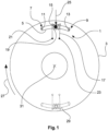
- figure 1 shows schematically an acceleration sensor 1 in an installed state on a vehicle wheel 3.
- the acceleration sensor 1 is part of an in 6 shown arrangement 601 for detecting a loss of grip of the vehicle wheel 3.
- the acceleration sensor 1 has a tube 5 with a longitudinal axis that forms a circular arc segment.
- the tube 5 has closed ends 7 and 9 .
- a contact surface 11 or 13 which faces the interior of the tube 5 , is arranged at each of the ends 7 and 9 .
- the tube 5 is filled with a fluid, not shown.
- a coil 17 surrounds the tube 5 by means of a coil wire 19 running around the tube several times.
- the coil 17 is supplied with current via two electrical contacts 21 and 23 in order to exert an attractive magnetic force on the ball 15 to exercise and to counteract a movement of the ball 15 in the direction of rotation 27 of the vehicle wheel 3 from a rest position 25 .
- the control unit 603 shown controls a power supply 613 of the coil 17.
- a positive acceleration of the vehicle wheel 3 in the direction of rotation 27 by a vehicle engine is taken into account. Ie when the vehicle wheel 3 is accelerated in the direction of rotation 27 by an increase in torque of the vehicle engine, the control unit 603 causes the coil to exert an increased force on the ball 15 so that it remains in the rest position 25 (unless other acceleration effects occur).
- a negative acceleration of the vehicle wheel 3 against the direction of rotation 27 by a vehicle brake is taken into account. That is to say, when the vehicle wheel 3 is decelerated by the vehicle brakes counter to the direction of rotation 27 , the control unit 603 causes the coil to exert an increased force on the ball 15 so that it remains in the rest position 25 .
- a loss of adhesion of the vehicle wheel 3 can be read from a movement of the ball 15 from the rest position 25 . If the vehicle wheel 3 spins, for example due to a loss of adhesion, the ball 15 moves in the viewing direction of FIG 1 Seen to the left from the rest position 25 out. If the vehicle wheel 3 blocks due to a loss of adhesion when braking the vehicle, the ball 15 moves in the viewing direction 1 seen to the right.
- a second duplex acceleration sensor 29 is arranged in vehicle wheel 3, which is functionally identical to first acceleration sensor 1.
- the second acceleration sensor 29 is arranged opposite the acceleration sensor 1 in relation to the center point 31 of the circular arc section. In other words: the second acceleration sensor 29 is offset by 180° in the direction of rotation 27 in relation to the first acceleration sensor 1 .
- the readout unit 608 comprises the 1 contact surfaces 11 and 13 shown. Communication between the evaluation electronics 607 and the readout unit 608 takes place wirelessly.
- the readout unit 608 detects when the ball 15 comes into contact with one of the contact surfaces 11 or 13 . A physical contact of the ball 15 with one of the contact surfaces 11 or 13 represents a loss of adhesion. This loss of liability is optically displayed to a vehicle driver 609 by means of a display 611 .
- the control unit 603 communicates wirelessly with the power supply 613 to control the force that the coil 17 exerts on the ball 15 .
- An actuating element 617 in the form of a button is arranged on a vehicle steering wheel 615 .
- an acceleration signal is sent to a control unit 619 .
- the control unit 619 is designed to control the vehicle engine and/or the vehicle brake in order to exert a positive or negative acceleration on the vehicle wheel 3 .
- a first method step A an acceleration sensor 1 arranged on the vehicle wheel 3 is used to test at regular time intervals whether there is a loss of adhesion. As soon as a loss of adhesion is detected, this loss of adhesion is verified in a method step B.
- the loss of adhesion is verified by the following steps: In a first method step i. the vehicle wheel 3 is accelerated by means of the vehicle brake and/or the vehicle engine. The acceleration is brought about by means of the control unit 619. In a further method step ii. the acceleration sensor 1 detects whether there is a loss of adhesion during acceleration.
- a method step C the vehicle driver 609 is informed about the verified loss of liability by means of the display 611 .
- the arrangement shown can also be used to carry out a second exemplary embodiment of a method according to the invention for detecting a loss of adhesion of the vehicle wheel 3 according to a third aspect of the invention.
- a first method step AA the actuating element 617 is actuated by the vehicle driver 609 .
- the actuation element 617 sends an acceleration signal to the control unit 619, which causes the vehicle wheel 3 to accelerate.
- a method step BB the vehicle wheel 3 is accelerated by means of the vehicle brake and/or by means of the vehicle engine.
- a loss of grip of the vehicle wheel 3 is detected by means of the acceleration sensor 1 in a method step CC.
- the acceleration according to the method step BB takes place through several successive accelerations of increasing intensity.
- the vehicle wheel is slightly accelerated. If no loss of grip is detected with this slight acceleration is, the vehicle wheel is again accelerated with an increased intensity.
- the intensity of the acceleration is increased with each new acceleration until a loss of grip is detected.
- a degree of grip can be determined using empirical values.
- the degree of adhesion can be displayed to the vehicle driver 609 in a method step DD using the display 611 .
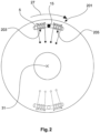
- FIG 2 shows schematically an acceleration sensor 201 in an installed state on a vehicle wheel 3.
- the acceleration sensor 201 is similar to that in FIG 1 Acceleration sensor 1 shown constructed. Identical and functionally identical elements are provided with the same reference symbols.
- the acceleration sensor 201 has two coils 203 and 205, each of which exerts a repulsive magnetic force on the ball 15 in order to counteract a movement of the ball 15 from the rest position.
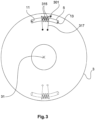
- FIG 3 shows schematically an acceleration sensor 301 in an installed state in a vehicle wheel 3.
- the acceleration sensor 301 is similar to that in FIG 1 Acceleration sensor 1 shown constructed. Identical and functionally identical elements are provided with the same reference symbols.
- In contrast to the in 1 Acceleration sensor 1 shown has acceleration sensor 301 a plurality of balls 315 .
- the coil 317 exerts an attractive force on the balls 315 to resist movement of the balls 315 from a rest position 25 .
- the acceleration sensor 401 has a chamber 403 in which a stock anchor-shaped mass 405 with a straight rod 407 and a circular arc-shaped section 409 is suspended.
- the suspension is at a first end of the rod 407, with the arcuate section 409 extending from a second end of the rod in two directions transverse to the longitudinal axis of the rod 407.
- a spiral spring 411 or 413 forms a connection between the rod 407 and an inner wall 415 or 417. The spiral springs 411 and 413 counteract the mass 405 pivoting out of a rest position 425.
- the chamber 403 has in each case a contact surface 419 or 421 with which one end 427 or 429 of the section 409 comes into contact when the mass 405 pivots out of the rest position 425 .
- This contact of an end 427 or 429 on a contact surface 419 or 421 is detected by means of a readout unit (not shown).
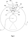
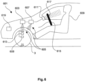
- FIG 5 shows schematically an acceleration sensor 501 in an installed state on a vehicle wheel 3.
- the acceleration sensor 501 is constructed similarly to the acceleration sensor 401. Identical and functionally identical elements are provided with the same reference symbols.
- the acceleration sensor 401 shown consists of the mass 505, which is arranged in a pendulum-like manner within the chamber 403, of a rod 407 and a spherical head mass 509.
- the rod 407 is pivotably suspended at a first end.
- the head mass 509 is located at a second end of the rod.
- acceleration sensor 501 has a plurality of contact surfaces 519 .
- the spherical mass 509 comes into contact with one of several contact surfaces 519.
- a readout unit detects which of the contact surfaces 519 the ball 509 is in contact with. The degree of deflection of the mass from the rest position 425 is thereby determined.
Landscapes
- Engineering & Computer Science (AREA)
- Physics & Mathematics (AREA)
- General Physics & Mathematics (AREA)
- Transportation (AREA)
- Mechanical Engineering (AREA)
- Fluid Mechanics (AREA)
- Regulating Braking Force (AREA)
- Tires In General (AREA)
- Control Of Driving Devices And Active Controlling Of Vehicle (AREA)
Applications Claiming Priority (3)
| Application Number | Priority Date | Filing Date | Title |
|---|---|---|---|
| DE201310217478 DE102013217478A1 (de) | 2013-09-03 | 2013-09-03 | Beschleunigungssensor, Anordnung und Verfahren zum Detektieren eines Haftungsverlusts eines Fahrzeugrades |
| EP14755636.9A EP3042211B1 (de) | 2013-09-03 | 2014-08-18 | Beschleunigungssensor, insbesondere duplex-beschleunigungssensor, anordnung und verfahren zum detektieren eines haftungsverlusts eines fahrzeugrades |
| PCT/EP2014/067585 WO2015032613A2 (de) | 2013-09-03 | 2014-08-18 | Beschleunigungssensor, insbesondere duplex-beschleunigungssensor, anordnung und verfahren zum detektieren eines haftungsverlusts eines fahrzeugrades |
Related Parent Applications (1)
| Application Number | Title | Priority Date | Filing Date |
|---|---|---|---|
| EP14755636.9A Division EP3042211B1 (de) | 2013-09-03 | 2014-08-18 | Beschleunigungssensor, insbesondere duplex-beschleunigungssensor, anordnung und verfahren zum detektieren eines haftungsverlusts eines fahrzeugrades |
Publications (2)
| Publication Number | Publication Date |
|---|---|
| EP3715862A1 EP3715862A1 (de) | 2020-09-30 |
| EP3715862B1 true EP3715862B1 (de) | 2023-04-26 |
Family
ID=51399639
Family Applications (2)
| Application Number | Title | Priority Date | Filing Date |
|---|---|---|---|
| EP14755636.9A Active EP3042211B1 (de) | 2013-09-03 | 2014-08-18 | Beschleunigungssensor, insbesondere duplex-beschleunigungssensor, anordnung und verfahren zum detektieren eines haftungsverlusts eines fahrzeugrades |
| EP20152887.4A Active EP3715862B1 (de) | 2013-09-03 | 2014-08-18 | Anordnung und verfahren zum detektieren eines haftungsverlusts eines fahrzeugrades |
Family Applications Before (1)
| Application Number | Title | Priority Date | Filing Date |
|---|---|---|---|
| EP14755636.9A Active EP3042211B1 (de) | 2013-09-03 | 2014-08-18 | Beschleunigungssensor, insbesondere duplex-beschleunigungssensor, anordnung und verfahren zum detektieren eines haftungsverlusts eines fahrzeugrades |
Country Status (5)
| Country | Link |
|---|---|
| US (2) | US9989554B2 (enExample) |
| EP (2) | EP3042211B1 (enExample) |
| JP (1) | JP6317450B2 (enExample) |
| DE (1) | DE102013217478A1 (enExample) |
| WO (1) | WO2015032613A2 (enExample) |
Families Citing this family (4)
| Publication number | Priority date | Publication date | Assignee | Title |
|---|---|---|---|---|
| DE102013217478A1 (de) | 2013-09-03 | 2015-03-05 | Bert Grundmann | Beschleunigungssensor, Anordnung und Verfahren zum Detektieren eines Haftungsverlusts eines Fahrzeugrades |
| JP6606115B2 (ja) * | 2017-03-14 | 2019-11-13 | 日信工業株式会社 | バーハンドル車両用ブレーキ液圧制御装置 |
| DE102017205312A1 (de) * | 2017-03-29 | 2018-10-04 | Siemens Aktiengesellschaft | Messanordnung und Verfahren zum Erzeugen eines Ausgangsmesssignals mit zumindest einem Beschleunigungssensor |
| CN112964353B (zh) * | 2021-04-21 | 2021-10-12 | 中国地震局工程力学研究所 | 一种双磁路传感器 |
Family Cites Families (43)
| Publication number | Priority date | Publication date | Assignee | Title |
|---|---|---|---|---|
| DE821562C (de) * | 1949-06-19 | 1951-11-19 | Ludwig Schart | Geraet, besonders fuer Kraftwagen, zur UEberwachung der beim Befahren von Kurven auftretenden Fliehkraft |
| US3668629A (en) * | 1969-02-25 | 1972-06-06 | Walter S Pawl | Vehicle anti-skid and anti-spin signal and control device |
| US3715003A (en) * | 1970-10-15 | 1973-02-06 | A Jubenville | Trailer antifishtail control system |
| US3744850A (en) * | 1971-03-08 | 1973-07-10 | D Barthlome | Automatic traction control system |
| JPS48108338U (enExample) | 1972-03-21 | 1973-12-14 | ||
| US3846748A (en) * | 1973-03-23 | 1974-11-05 | C Hopwood | Signaling system and sensor |
| US3946173A (en) | 1975-01-06 | 1976-03-23 | Haber Terry M | Acceleration/deceleration actuating mechanism for wrist instruments |
| DE2644606A1 (de) * | 1976-10-02 | 1978-04-06 | Daimler Benz Ag | Magnetisch betaetigter elektrischer schalter |
| DE3206694A1 (de) * | 1982-02-25 | 1983-09-01 | Vdo Adolf Schindling Ag, 6000 Frankfurt | Einrichtung zur ueberwachung des schlupfes an raedern von kraftfahrzeugen |
| US4571844A (en) | 1982-06-09 | 1986-02-25 | Jeco Co., Ltd. | Angle change detector |
| DE3506758A1 (de) | 1985-02-26 | 1986-08-28 | Gerhard Dipl.-Phys. 8702 Himmelstadt Karl | Beschleunigungsmesser |
| EP0317962A3 (de) | 1987-11-27 | 1990-07-11 | BRITAX-KOLB GMBH & CO | Beschleunigungssensor für Sicherungssysteme von Kraftfahrzeugen |
| JP2649696B2 (ja) * | 1988-05-26 | 1997-09-03 | 曙ブレーキ工業株式会社 | 車両のトラクション制御方法 |
| US5009294A (en) * | 1990-01-19 | 1991-04-23 | General Motors Corporation | Vehicle traction control system |
| US5149925A (en) * | 1990-09-05 | 1992-09-22 | Automotive Systems Laboratory, Inc. | Quick-response accelerometer |
| CH681931A5 (enExample) | 1991-05-29 | 1993-06-15 | Ascom Zelcom Ag | |
| JPH0610871U (ja) | 1992-07-10 | 1994-02-10 | 日本電子機器株式会社 | 加速度センサ |
| US5586028A (en) * | 1993-12-07 | 1996-12-17 | Honda Giken Kogyo Kabushiki Kaisha | Road surface condition-detecting system and anti-lock brake system employing same |
| DE19527805C2 (de) * | 1994-07-29 | 2000-11-23 | Toyota Motor Co Ltd | Brems-Steuervorrichtung, die in der Lage ist, eine Traktions-Kontrolle eines Fahrzeug-Antriebsrades durchzuführen und die eine Einrichtung zur Reduzierung des Zufuhrdruckes der Pumpe während der Traktions-Kontrolle aufweist |
| DE19602428A1 (de) | 1995-01-24 | 1996-07-25 | Georg Hagmeier | Warnblinkanordnung |
| JPH09280941A (ja) | 1996-02-15 | 1997-10-31 | Tadatoshi Goto | 振動検知装置 |
| JPH10160460A (ja) | 1996-10-04 | 1998-06-19 | Tadatoshi Goto | 傾斜検出装置 |
| DE19813941A1 (de) | 1998-03-28 | 1999-10-07 | Benecke Wolfgang | Mikromechanischer Beschleunigungssensor |
| DE19930779B4 (de) | 1999-07-03 | 2010-05-06 | Robert Bosch Gmbh | Mikromechanisches Bauelement |
| JP2001155601A (ja) | 1999-11-29 | 2001-06-08 | Tokin Ceramics Corp | 傾斜角度検出センサ |
| TW486438B (en) | 2000-03-09 | 2002-05-11 | Sumitomo Rubber Ind | Device and method for determining coefficient of road surface friction |
| DE10223214A1 (de) | 2002-05-24 | 2003-12-18 | Siemens Ag | Verfahren zum Zuordnen von Reifenmodulen zu Radpositionen eines Reifendrucküberwachungssytems für ein Kraftfahrzeug und Vorrichtung zum Überwachen des Reifendrucks |
| EP1481861B1 (en) * | 2003-05-28 | 2007-07-04 | Ford Global Technologies, LLC | A method and a computer readable storage device for estimating tirc-to-road friction |
| FR2857576B1 (fr) | 2003-07-16 | 2005-10-14 | Depuy France | Dispositif d'aide pour l'implantation de protheses totales du genou |
| MXPA06008220A (es) | 2004-01-20 | 2007-03-30 | Schrader Bridgeport Int Inc | Deteccion de movimiento usando un sensor de choque en un sistema de monitoreo remoto para presion de llantas. |
| US7356401B2 (en) | 2004-08-13 | 2008-04-08 | Arvinmeritor Technology, Llc | Drivetrain protection and management system |
| JP2006072588A (ja) | 2004-09-01 | 2006-03-16 | Ts Photon:Kk | タイヤ内外の環境監視システム |
| DE102004051654A1 (de) * | 2004-10-22 | 2006-04-27 | "Stiftung Caesar" (Center Of Advanced European Studies And Research) | Beschleunigungssensoren im Reifen |
| JP2006142993A (ja) | 2004-11-19 | 2006-06-08 | Yokohama Rubber Co Ltd:The | 加速度センサ装着タイヤ |
| US8442735B2 (en) * | 2005-06-15 | 2013-05-14 | Ford Global Technologies, Llc | Traction control system and method |
| DE102007014765A1 (de) | 2007-03-28 | 2008-10-02 | Robert Bosch Gmbh | Verfahren und Vorrichtung zur Überwachung von Betriebsparametern an Reifen |
| DE102007052749A1 (de) | 2007-11-06 | 2009-05-07 | Robert Bosch Gmbh | Verfahren zum Detektieren von Radschlupf |
| US20110113880A1 (en) | 2008-05-15 | 2011-05-19 | Continental Teves Ag & Co. Ohg | Micromechanical acceleration sensor |
| DE102009045305B4 (de) | 2009-10-02 | 2021-01-14 | Robert Bosch Gmbh | Verfahren zur Ermittlung einer Drehrichtung eines rotierenden Körpers und Radsensormodul |
| GB2478790B (en) | 2010-03-19 | 2016-06-15 | Univ Southampton | Apparatus and method of vibration control |
| ES2558378T3 (es) * | 2011-06-21 | 2016-02-03 | Siemens S.A.S. | Acelerómetro pendular |
| EP2581258A1 (de) | 2011-10-13 | 2013-04-17 | Siemens Aktiengesellschaft | Kraftwagen mit wenigstens einem elektrischen Antriebsmotor und Verfahren zum Betreiben einer Steuereinrichtung eines Kraftwagens |
| DE102013217478A1 (de) | 2013-09-03 | 2015-03-05 | Bert Grundmann | Beschleunigungssensor, Anordnung und Verfahren zum Detektieren eines Haftungsverlusts eines Fahrzeugrades |
-
2013
- 2013-09-03 DE DE201310217478 patent/DE102013217478A1/de not_active Withdrawn
-
2014
- 2014-08-18 US US14/916,147 patent/US9989554B2/en active Active
- 2014-08-18 JP JP2016539460A patent/JP6317450B2/ja active Active
- 2014-08-18 EP EP14755636.9A patent/EP3042211B1/de active Active
- 2014-08-18 WO PCT/EP2014/067585 patent/WO2015032613A2/de not_active Ceased
- 2014-08-18 EP EP20152887.4A patent/EP3715862B1/de active Active
-
2018
- 2018-04-24 US US15/961,688 patent/US10882499B2/en active Active
Also Published As
| Publication number | Publication date |
|---|---|
| EP3042211B1 (de) | 2020-01-22 |
| WO2015032613A3 (de) | 2015-04-30 |
| WO2015032613A2 (de) | 2015-03-12 |
| US20160195568A1 (en) | 2016-07-07 |
| EP3715862A1 (de) | 2020-09-30 |
| EP3042211A2 (de) | 2016-07-13 |
| DE102013217478A1 (de) | 2015-03-05 |
| US20180246140A1 (en) | 2018-08-30 |
| JP6317450B2 (ja) | 2018-04-25 |
| US10882499B2 (en) | 2021-01-05 |
| JP2016532120A (ja) | 2016-10-13 |
| US9989554B2 (en) | 2018-06-05 |
Similar Documents
| Publication | Publication Date | Title |
|---|---|---|
| EP2888721B1 (de) | Verfahren und vorrichtung zum ermitteln einer gefahrenquelle einer fahrstrecke | |
| EP2734425B1 (de) | Verfahren zur verbesserung der fahrstabilität | |
| DE102004016288B3 (de) | Verfahren zur Bestimmung eines Reibwerts | |
| EP2355990B1 (de) | Verfahren zur ermittlung des fahrbahnzustands eines von einem kraftfahrzeug befahrenen streckenabschnitts | |
| DE102017111170A1 (de) | Automatisches fahrsystem zum auswerten von fahrspurausscherungen und verfahren zur verwendung desselben | |
| DE102004050052B4 (de) | Verfahren zur Fahrerwarnung beim Abstellen eines Kraftfahrzeugs auf längsgeneigter Fahrbahn ohne Radeinschlag | |
| EP3715862B1 (de) | Anordnung und verfahren zum detektieren eines haftungsverlusts eines fahrzeugrades | |
| DE102013219662B3 (de) | Verfahren, Steuergerät und System zum Ermitteln einer Profiltiefe eines Profils zumindest eines Reifens | |
| DE4435160A1 (de) | Einrichtung zur Ermittlung der Umfangskraft eines Fahrzeugrades | |
| DE102014016567A1 (de) | Verfahren zum Bestimmen einer Ausweichtrajektorie und Fahrerassistenzsystem dafür | |
| DE102006061483A1 (de) | Verfahren und Vorrichtung zur Bestimmung des Rollwinkels eines Kraftrades | |
| EP3626556B1 (de) | Verfahren zur notfallreaktion bei einem reifendruckverlust, sowie fahrzeug | |
| DE102015000931B4 (de) | Verfahren zur Bestimmung einer Referenzgeschwindigkeit für ein Fahrzeug mit mindestens zwei Rädern sowie eine Steuereinrichtung und eine Bremsvorrichtung | |
| DE102007044761A1 (de) | Verfahren und Vorrichtung zur Bestimmung eines sich entlang einer Bewegungsbahn eines Fahrzeuges erstreckenden Fahrschlauches | |
| EP1045783B1 (de) | Vorrichtung und verfahren zum begrenzen einer rückrollgeschwindigkeit eines kraftfahrzeuges | |
| DE102016220692A1 (de) | Verfahren zur Reibwertermittlung und zum Betreiben eines Kraftfahrzeugs | |
| DE10232362A1 (de) | Verfahren und Vorrichtung zur Stabilisierung eines einspurigen Kraftfahrzeugs | |
| DE102004039405B4 (de) | Sensorvorrichtung und Verfahren zum Ermitteln einer Seite eines Fahrzeugs, an der ein Rad mit einer Sensorvorrichtung angeordnet ist | |
| EP3077261B1 (de) | Zweiradfahrzeug mit federwegbasierter antriebs- und bremsleistungsbegrenzung sowie steuereinheit hierzu | |
| EP4161810B1 (de) | Achse und verfahren zum kompensieren einer verzögerung | |
| DE102010023196A1 (de) | Verfahren und Vorrichtung zur Vordermannerkennung | |
| DE10220575A1 (de) | Verfahren zur Erkennung einer Steilwandkurve an einem in eine solche Kurve hineinbewegten Fahrzeug | |
| DE102013013317B3 (de) | Verfahren zur Ermittlung der Seitenführungskräfte von Rädern eines mehrspurigen Fahrzeuges | |
| DE102015212351A1 (de) | Verfahren zur Ermittlung einer Beladung eines Aufbaus eines Fahrzeugs | |
| EP2879927B1 (de) | Verfahren und vorrichtung zur bestimmung einer querneigung einer von einem zweiradfahrzeug befahrenen fahrbahnoberfläche |
Legal Events
| Date | Code | Title | Description |
|---|---|---|---|
| PUAI | Public reference made under article 153(3) epc to a published international application that has entered the european phase |
Free format text: ORIGINAL CODE: 0009012 |
|
| STAA | Information on the status of an ep patent application or granted ep patent |
Free format text: STATUS: THE APPLICATION HAS BEEN PUBLISHED |
|
| AC | Divisional application: reference to earlier application |
Ref document number: 3042211 Country of ref document: EP Kind code of ref document: P |
|
| AK | Designated contracting states |
Kind code of ref document: A1 Designated state(s): AL AT BE BG CH CY CZ DE DK EE ES FI FR GB GR HR HU IE IS IT LI LT LU LV MC MK MT NL NO PL PT RO RS SE SI SK SM TR |
|
| REG | Reference to a national code |
Ref country code: HK Ref legal event code: DE Ref document number: 40031999 Country of ref document: HK |
|
| STAA | Information on the status of an ep patent application or granted ep patent |
Free format text: STATUS: REQUEST FOR EXAMINATION WAS MADE |
|
| 17P | Request for examination filed |
Effective date: 20210329 |
|
| RBV | Designated contracting states (corrected) |
Designated state(s): AL AT BE BG CH CY CZ DE DK EE ES FI FR GB GR HR HU IE IS IT LI LT LU LV MC MK MT NL NO PL PT RO RS SE SI SK SM TR |
|
| STAA | Information on the status of an ep patent application or granted ep patent |
Free format text: STATUS: EXAMINATION IS IN PROGRESS |
|
| 17Q | First examination report despatched |
Effective date: 20220422 |
|
| GRAP | Despatch of communication of intention to grant a patent |
Free format text: ORIGINAL CODE: EPIDOSNIGR1 |
|
| STAA | Information on the status of an ep patent application or granted ep patent |
Free format text: STATUS: GRANT OF PATENT IS INTENDED |
|
| INTG | Intention to grant announced |
Effective date: 20221107 |
|
| GRAS | Grant fee paid |
Free format text: ORIGINAL CODE: EPIDOSNIGR3 |
|
| GRAA | (expected) grant |
Free format text: ORIGINAL CODE: 0009210 |
|
| STAA | Information on the status of an ep patent application or granted ep patent |
Free format text: STATUS: THE PATENT HAS BEEN GRANTED |
|
| AC | Divisional application: reference to earlier application |
Ref document number: 3042211 Country of ref document: EP Kind code of ref document: P |
|
| AK | Designated contracting states |
Kind code of ref document: B1 Designated state(s): AL AT BE BG CH CY CZ DE DK EE ES FI FR GB GR HR HU IE IS IT LI LT LU LV MC MK MT NL NO PL PT RO RS SE SI SK SM TR |
|
| REG | Reference to a national code |
Ref country code: GB Ref legal event code: FG4D Free format text: NOT ENGLISH |
|
| REG | Reference to a national code |
Ref country code: CH Ref legal event code: EP |
|
| REG | Reference to a national code |
Ref country code: DE Ref legal event code: R096 Ref document number: 502014016551 Country of ref document: DE |
|
| REG | Reference to a national code |
Ref country code: AT Ref legal event code: REF Ref document number: 1563193 Country of ref document: AT Kind code of ref document: T Effective date: 20230515 |
|
| REG | Reference to a national code |
Ref country code: IE Ref legal event code: FG4D Free format text: LANGUAGE OF EP DOCUMENT: GERMAN |
|
| REG | Reference to a national code |
Ref country code: SE Ref legal event code: TRGR |
|
| REG | Reference to a national code |
Ref country code: LT Ref legal event code: MG9D |
|
| REG | Reference to a national code |
Ref country code: NL Ref legal event code: MP Effective date: 20230426 |
|
| PG25 | Lapsed in a contracting state [announced via postgrant information from national office to epo] |
Ref country code: NL Free format text: LAPSE BECAUSE OF FAILURE TO SUBMIT A TRANSLATION OF THE DESCRIPTION OR TO PAY THE FEE WITHIN THE PRESCRIBED TIME-LIMIT Effective date: 20230426 |
|
| PG25 | Lapsed in a contracting state [announced via postgrant information from national office to epo] |
Ref country code: PT Free format text: LAPSE BECAUSE OF FAILURE TO SUBMIT A TRANSLATION OF THE DESCRIPTION OR TO PAY THE FEE WITHIN THE PRESCRIBED TIME-LIMIT Effective date: 20230828 Ref country code: NO Free format text: LAPSE BECAUSE OF FAILURE TO SUBMIT A TRANSLATION OF THE DESCRIPTION OR TO PAY THE FEE WITHIN THE PRESCRIBED TIME-LIMIT Effective date: 20230726 Ref country code: ES Free format text: LAPSE BECAUSE OF FAILURE TO SUBMIT A TRANSLATION OF THE DESCRIPTION OR TO PAY THE FEE WITHIN THE PRESCRIBED TIME-LIMIT Effective date: 20230426 |
|
| PG25 | Lapsed in a contracting state [announced via postgrant information from national office to epo] |
Ref country code: RS Free format text: LAPSE BECAUSE OF FAILURE TO SUBMIT A TRANSLATION OF THE DESCRIPTION OR TO PAY THE FEE WITHIN THE PRESCRIBED TIME-LIMIT Effective date: 20230426 Ref country code: PL Free format text: LAPSE BECAUSE OF FAILURE TO SUBMIT A TRANSLATION OF THE DESCRIPTION OR TO PAY THE FEE WITHIN THE PRESCRIBED TIME-LIMIT Effective date: 20230426 Ref country code: LV Free format text: LAPSE BECAUSE OF FAILURE TO SUBMIT A TRANSLATION OF THE DESCRIPTION OR TO PAY THE FEE WITHIN THE PRESCRIBED TIME-LIMIT Effective date: 20230426 Ref country code: LT Free format text: LAPSE BECAUSE OF FAILURE TO SUBMIT A TRANSLATION OF THE DESCRIPTION OR TO PAY THE FEE WITHIN THE PRESCRIBED TIME-LIMIT Effective date: 20230426 Ref country code: IS Free format text: LAPSE BECAUSE OF FAILURE TO SUBMIT A TRANSLATION OF THE DESCRIPTION OR TO PAY THE FEE WITHIN THE PRESCRIBED TIME-LIMIT Effective date: 20230826 Ref country code: HR Free format text: LAPSE BECAUSE OF FAILURE TO SUBMIT A TRANSLATION OF THE DESCRIPTION OR TO PAY THE FEE WITHIN THE PRESCRIBED TIME-LIMIT Effective date: 20230426 Ref country code: GR Free format text: LAPSE BECAUSE OF FAILURE TO SUBMIT A TRANSLATION OF THE DESCRIPTION OR TO PAY THE FEE WITHIN THE PRESCRIBED TIME-LIMIT Effective date: 20230727 |
|
| PG25 | Lapsed in a contracting state [announced via postgrant information from national office to epo] |
Ref country code: FI Free format text: LAPSE BECAUSE OF FAILURE TO SUBMIT A TRANSLATION OF THE DESCRIPTION OR TO PAY THE FEE WITHIN THE PRESCRIBED TIME-LIMIT Effective date: 20230426 |
|
| PG25 | Lapsed in a contracting state [announced via postgrant information from national office to epo] |
Ref country code: SK Free format text: LAPSE BECAUSE OF FAILURE TO SUBMIT A TRANSLATION OF THE DESCRIPTION OR TO PAY THE FEE WITHIN THE PRESCRIBED TIME-LIMIT Effective date: 20230426 |
|
| REG | Reference to a national code |
Ref country code: DE Ref legal event code: R097 Ref document number: 502014016551 Country of ref document: DE |
|
| PG25 | Lapsed in a contracting state [announced via postgrant information from national office to epo] |
Ref country code: SM Free format text: LAPSE BECAUSE OF FAILURE TO SUBMIT A TRANSLATION OF THE DESCRIPTION OR TO PAY THE FEE WITHIN THE PRESCRIBED TIME-LIMIT Effective date: 20230426 Ref country code: SK Free format text: LAPSE BECAUSE OF FAILURE TO SUBMIT A TRANSLATION OF THE DESCRIPTION OR TO PAY THE FEE WITHIN THE PRESCRIBED TIME-LIMIT Effective date: 20230426 Ref country code: RO Free format text: LAPSE BECAUSE OF FAILURE TO SUBMIT A TRANSLATION OF THE DESCRIPTION OR TO PAY THE FEE WITHIN THE PRESCRIBED TIME-LIMIT Effective date: 20230426 Ref country code: EE Free format text: LAPSE BECAUSE OF FAILURE TO SUBMIT A TRANSLATION OF THE DESCRIPTION OR TO PAY THE FEE WITHIN THE PRESCRIBED TIME-LIMIT Effective date: 20230426 Ref country code: DK Free format text: LAPSE BECAUSE OF FAILURE TO SUBMIT A TRANSLATION OF THE DESCRIPTION OR TO PAY THE FEE WITHIN THE PRESCRIBED TIME-LIMIT Effective date: 20230426 Ref country code: CZ Free format text: LAPSE BECAUSE OF FAILURE TO SUBMIT A TRANSLATION OF THE DESCRIPTION OR TO PAY THE FEE WITHIN THE PRESCRIBED TIME-LIMIT Effective date: 20230426 |
|
| PLBE | No opposition filed within time limit |
Free format text: ORIGINAL CODE: 0009261 |
|
| STAA | Information on the status of an ep patent application or granted ep patent |
Free format text: STATUS: NO OPPOSITION FILED WITHIN TIME LIMIT |
|
| PG25 | Lapsed in a contracting state [announced via postgrant information from national office to epo] |
Ref country code: MC Free format text: LAPSE BECAUSE OF FAILURE TO SUBMIT A TRANSLATION OF THE DESCRIPTION OR TO PAY THE FEE WITHIN THE PRESCRIBED TIME-LIMIT Effective date: 20230426 |
|
| REG | Reference to a national code |
Ref country code: CH Ref legal event code: PL |
|
| PG25 | Lapsed in a contracting state [announced via postgrant information from national office to epo] |
Ref country code: MC Free format text: LAPSE BECAUSE OF FAILURE TO SUBMIT A TRANSLATION OF THE DESCRIPTION OR TO PAY THE FEE WITHIN THE PRESCRIBED TIME-LIMIT Effective date: 20230426 |
|
| 26N | No opposition filed |
Effective date: 20240129 |
|
| PG25 | Lapsed in a contracting state [announced via postgrant information from national office to epo] |
Ref country code: LU Free format text: LAPSE BECAUSE OF NON-PAYMENT OF DUE FEES Effective date: 20230818 |
|
| PG25 | Lapsed in a contracting state [announced via postgrant information from national office to epo] |
Ref country code: LU Free format text: LAPSE BECAUSE OF NON-PAYMENT OF DUE FEES Effective date: 20230818 Ref country code: CH Free format text: LAPSE BECAUSE OF NON-PAYMENT OF DUE FEES Effective date: 20230831 |
|
| PG25 | Lapsed in a contracting state [announced via postgrant information from national office to epo] |
Ref country code: SI Free format text: LAPSE BECAUSE OF FAILURE TO SUBMIT A TRANSLATION OF THE DESCRIPTION OR TO PAY THE FEE WITHIN THE PRESCRIBED TIME-LIMIT Effective date: 20230426 |
|
| REG | Reference to a national code |
Ref country code: BE Ref legal event code: MM Effective date: 20230831 |
|
| REG | Reference to a national code |
Ref country code: IE Ref legal event code: MM4A |
|
| PG25 | Lapsed in a contracting state [announced via postgrant information from national office to epo] |
Ref country code: SI Free format text: LAPSE BECAUSE OF FAILURE TO SUBMIT A TRANSLATION OF THE DESCRIPTION OR TO PAY THE FEE WITHIN THE PRESCRIBED TIME-LIMIT Effective date: 20230426 |
|
| PG25 | Lapsed in a contracting state [announced via postgrant information from national office to epo] |
Ref country code: IE Free format text: LAPSE BECAUSE OF NON-PAYMENT OF DUE FEES Effective date: 20230818 |
|
| PG25 | Lapsed in a contracting state [announced via postgrant information from national office to epo] |
Ref country code: IE Free format text: LAPSE BECAUSE OF NON-PAYMENT OF DUE FEES Effective date: 20230818 |
|
| PG25 | Lapsed in a contracting state [announced via postgrant information from national office to epo] |
Ref country code: BE Free format text: LAPSE BECAUSE OF NON-PAYMENT OF DUE FEES Effective date: 20230831 |
|
| REG | Reference to a national code |
Ref country code: AT Ref legal event code: MM01 Ref document number: 1563193 Country of ref document: AT Kind code of ref document: T Effective date: 20230818 |
|
| PG25 | Lapsed in a contracting state [announced via postgrant information from national office to epo] |
Ref country code: AT Free format text: LAPSE BECAUSE OF NON-PAYMENT OF DUE FEES Effective date: 20230818 |
|
| PG25 | Lapsed in a contracting state [announced via postgrant information from national office to epo] |
Ref country code: AT Free format text: LAPSE BECAUSE OF NON-PAYMENT OF DUE FEES Effective date: 20230818 |
|
| PG25 | Lapsed in a contracting state [announced via postgrant information from national office to epo] |
Ref country code: BG Free format text: LAPSE BECAUSE OF FAILURE TO SUBMIT A TRANSLATION OF THE DESCRIPTION OR TO PAY THE FEE WITHIN THE PRESCRIBED TIME-LIMIT Effective date: 20230426 |
|
| PG25 | Lapsed in a contracting state [announced via postgrant information from national office to epo] |
Ref country code: BG Free format text: LAPSE BECAUSE OF FAILURE TO SUBMIT A TRANSLATION OF THE DESCRIPTION OR TO PAY THE FEE WITHIN THE PRESCRIBED TIME-LIMIT Effective date: 20230426 |
|
| PG25 | Lapsed in a contracting state [announced via postgrant information from national office to epo] |
Ref country code: CY Free format text: LAPSE BECAUSE OF FAILURE TO SUBMIT A TRANSLATION OF THE DESCRIPTION OR TO PAY THE FEE WITHIN THE PRESCRIBED TIME-LIMIT; INVALID AB INITIO Effective date: 20140818 |
|
| PG25 | Lapsed in a contracting state [announced via postgrant information from national office to epo] |
Ref country code: HU Free format text: LAPSE BECAUSE OF FAILURE TO SUBMIT A TRANSLATION OF THE DESCRIPTION OR TO PAY THE FEE WITHIN THE PRESCRIBED TIME-LIMIT; INVALID AB INITIO Effective date: 20140818 |
|
| PGFP | Annual fee paid to national office [announced via postgrant information from national office to epo] |
Ref country code: DE Payment date: 20250908 Year of fee payment: 12 |
|
| PGFP | Annual fee paid to national office [announced via postgrant information from national office to epo] |
Ref country code: IT Payment date: 20250829 Year of fee payment: 12 |
|
| PGFP | Annual fee paid to national office [announced via postgrant information from national office to epo] |
Ref country code: GB Payment date: 20250822 Year of fee payment: 12 |
|
| PGFP | Annual fee paid to national office [announced via postgrant information from national office to epo] |
Ref country code: FR Payment date: 20250821 Year of fee payment: 12 |
|
| PGFP | Annual fee paid to national office [announced via postgrant information from national office to epo] |
Ref country code: SE Payment date: 20250821 Year of fee payment: 12 |
|
| PG25 | Lapsed in a contracting state [announced via postgrant information from national office to epo] |
Ref country code: TR Free format text: LAPSE BECAUSE OF FAILURE TO SUBMIT A TRANSLATION OF THE DESCRIPTION OR TO PAY THE FEE WITHIN THE PRESCRIBED TIME-LIMIT Effective date: 20230426 |