EP3715862B1 - Arrangement and method for detecting loss of adhesion of a vehicle wheel - Google Patents
Arrangement and method for detecting loss of adhesion of a vehicle wheel Download PDFInfo
- Publication number
- EP3715862B1 EP3715862B1 EP20152887.4A EP20152887A EP3715862B1 EP 3715862 B1 EP3715862 B1 EP 3715862B1 EP 20152887 A EP20152887 A EP 20152887A EP 3715862 B1 EP3715862 B1 EP 3715862B1
- Authority
- EP
- European Patent Office
- Prior art keywords
- vehicle
- loss
- acceleration
- adhesion
- vehicle wheel
- Prior art date
- Legal status (The legal status is an assumption and is not a legal conclusion. Google has not performed a legal analysis and makes no representation as to the accuracy of the status listed.)
- Active
Links
- 238000000034 method Methods 0.000 title claims description 38
- 230000001133 acceleration Effects 0.000 claims description 202
- 238000012360 testing method Methods 0.000 claims description 16
- 230000004044 response Effects 0.000 claims description 5
- 238000012795 verification Methods 0.000 claims description 3
- 238000011084 recovery Methods 0.000 claims description 2
- 230000008859 change Effects 0.000 description 7
- 230000000694 effects Effects 0.000 description 7
- 238000011156 evaluation Methods 0.000 description 6
- 239000004033 plastic Substances 0.000 description 5
- 230000005291 magnetic effect Effects 0.000 description 4
- XLYOFNOQVPJJNP-UHFFFAOYSA-N water Substances O XLYOFNOQVPJJNP-UHFFFAOYSA-N 0.000 description 4
- 230000006399 behavior Effects 0.000 description 3
- 230000008901 benefit Effects 0.000 description 3
- 238000001514 detection method Methods 0.000 description 3
- 238000011161 development Methods 0.000 description 3
- 239000012530 fluid Substances 0.000 description 3
- 230000006870 function Effects 0.000 description 3
- 238000009434 installation Methods 0.000 description 3
- 230000035945 sensitivity Effects 0.000 description 3
- 239000000725 suspension Substances 0.000 description 3
- 230000007704 transition Effects 0.000 description 3
- 239000000919 ceramic Substances 0.000 description 2
- 238000013461 design Methods 0.000 description 2
- 239000000428 dust Substances 0.000 description 2
- 239000003302 ferromagnetic material Substances 0.000 description 2
- 239000007788 liquid Substances 0.000 description 2
- 238000012423 maintenance Methods 0.000 description 2
- 238000004519 manufacturing process Methods 0.000 description 2
- 239000000463 material Substances 0.000 description 2
- 239000002184 metal Substances 0.000 description 2
- 238000012544 monitoring process Methods 0.000 description 2
- 230000001846 repelling effect Effects 0.000 description 2
- 230000003068 static effect Effects 0.000 description 2
- 230000028838 turning behavior Effects 0.000 description 2
- 230000005483 Hooke's law Effects 0.000 description 1
- 206010021703 Indifference Diseases 0.000 description 1
- 240000004752 Laburnum anagyroides Species 0.000 description 1
- 229910000831 Steel Inorganic materials 0.000 description 1
- 230000015572 biosynthetic process Effects 0.000 description 1
- 238000004364 calculation method Methods 0.000 description 1
- 238000004891 communication Methods 0.000 description 1
- 238000004590 computer program Methods 0.000 description 1
- 238000009795 derivation Methods 0.000 description 1
- 238000009826 distribution Methods 0.000 description 1
- JKMBMIMLVFMXRW-LYYFRFARSA-N epicocconone Chemical class C1=C2C[C@@H](CO)OC=C2C(=O)[C@]2(C)C1=C(C(/O)=C/C(=O)/C=C/C=C/C=C/C)C(=O)O2 JKMBMIMLVFMXRW-LYYFRFARSA-N 0.000 description 1
- 230000005294 ferromagnetic effect Effects 0.000 description 1
- 230000006698 induction Effects 0.000 description 1
- 238000005457 optimization Methods 0.000 description 1
- 230000001151 other effect Effects 0.000 description 1
- 230000002265 prevention Effects 0.000 description 1
- 230000008569 process Effects 0.000 description 1
- 230000009023 proprioceptive sensation Effects 0.000 description 1
- 238000009987 spinning Methods 0.000 description 1
- 239000010959 steel Substances 0.000 description 1
- 239000013589 supplement Substances 0.000 description 1
Images

Classifications
-
- B—PERFORMING OPERATIONS; TRANSPORTING
- B60—VEHICLES IN GENERAL
- B60T—VEHICLE BRAKE CONTROL SYSTEMS OR PARTS THEREOF; BRAKE CONTROL SYSTEMS OR PARTS THEREOF, IN GENERAL; ARRANGEMENT OF BRAKING ELEMENTS ON VEHICLES IN GENERAL; PORTABLE DEVICES FOR PREVENTING UNWANTED MOVEMENT OF VEHICLES; VEHICLE MODIFICATIONS TO FACILITATE COOLING OF BRAKES
- B60T8/00—Arrangements for adjusting wheel-braking force to meet varying vehicular or ground-surface conditions, e.g. limiting or varying distribution of braking force
- B60T8/17—Using electrical or electronic regulation means to control braking
- B60T8/172—Determining control parameters used in the regulation, e.g. by calculations involving measured or detected parameters
- B60T8/1725—Using tyre sensors, e.g. Sidewall Torsion sensors [SWT]
-
- B—PERFORMING OPERATIONS; TRANSPORTING
- B60—VEHICLES IN GENERAL
- B60T—VEHICLE BRAKE CONTROL SYSTEMS OR PARTS THEREOF; BRAKE CONTROL SYSTEMS OR PARTS THEREOF, IN GENERAL; ARRANGEMENT OF BRAKING ELEMENTS ON VEHICLES IN GENERAL; PORTABLE DEVICES FOR PREVENTING UNWANTED MOVEMENT OF VEHICLES; VEHICLE MODIFICATIONS TO FACILITATE COOLING OF BRAKES
- B60T8/00—Arrangements for adjusting wheel-braking force to meet varying vehicular or ground-surface conditions, e.g. limiting or varying distribution of braking force
- B60T8/17—Using electrical or electronic regulation means to control braking
- B60T8/176—Brake regulation specially adapted to prevent excessive wheel slip during vehicle deceleration, e.g. ABS
- B60T8/1761—Brake regulation specially adapted to prevent excessive wheel slip during vehicle deceleration, e.g. ABS responsive to wheel or brake dynamics, e.g. wheel slip, wheel acceleration or rate of change of brake fluid pressure
-
- G—PHYSICS
- G01—MEASURING; TESTING
- G01P—MEASURING LINEAR OR ANGULAR SPEED, ACCELERATION, DECELERATION, OR SHOCK; INDICATING PRESENCE, ABSENCE, OR DIRECTION, OF MOVEMENT
- G01P15/00—Measuring acceleration; Measuring deceleration; Measuring shock, i.e. sudden change of acceleration
- G01P15/02—Measuring acceleration; Measuring deceleration; Measuring shock, i.e. sudden change of acceleration by making use of inertia forces using solid seismic masses
- G01P15/08—Measuring acceleration; Measuring deceleration; Measuring shock, i.e. sudden change of acceleration by making use of inertia forces using solid seismic masses with conversion into electric or magnetic values
- G01P15/0891—Measuring acceleration; Measuring deceleration; Measuring shock, i.e. sudden change of acceleration by making use of inertia forces using solid seismic masses with conversion into electric or magnetic values with indication of predetermined acceleration values
-
- G—PHYSICS
- G01—MEASURING; TESTING
- G01P—MEASURING LINEAR OR ANGULAR SPEED, ACCELERATION, DECELERATION, OR SHOCK; INDICATING PRESENCE, ABSENCE, OR DIRECTION, OF MOVEMENT
- G01P15/00—Measuring acceleration; Measuring deceleration; Measuring shock, i.e. sudden change of acceleration
- G01P15/02—Measuring acceleration; Measuring deceleration; Measuring shock, i.e. sudden change of acceleration by making use of inertia forces using solid seismic masses
- G01P15/08—Measuring acceleration; Measuring deceleration; Measuring shock, i.e. sudden change of acceleration by making use of inertia forces using solid seismic masses with conversion into electric or magnetic values
- G01P15/105—Measuring acceleration; Measuring deceleration; Measuring shock, i.e. sudden change of acceleration by making use of inertia forces using solid seismic masses with conversion into electric or magnetic values by magnetically sensitive devices
-
- G—PHYSICS
- G01—MEASURING; TESTING
- G01P—MEASURING LINEAR OR ANGULAR SPEED, ACCELERATION, DECELERATION, OR SHOCK; INDICATING PRESENCE, ABSENCE, OR DIRECTION, OF MOVEMENT
- G01P15/00—Measuring acceleration; Measuring deceleration; Measuring shock, i.e. sudden change of acceleration
- G01P15/02—Measuring acceleration; Measuring deceleration; Measuring shock, i.e. sudden change of acceleration by making use of inertia forces using solid seismic masses
- G01P15/08—Measuring acceleration; Measuring deceleration; Measuring shock, i.e. sudden change of acceleration by making use of inertia forces using solid seismic masses with conversion into electric or magnetic values
- G01P15/135—Measuring acceleration; Measuring deceleration; Measuring shock, i.e. sudden change of acceleration by making use of inertia forces using solid seismic masses with conversion into electric or magnetic values by making use of contacts which are actuated by a movable inertial mass
-
- B—PERFORMING OPERATIONS; TRANSPORTING
- B60—VEHICLES IN GENERAL
- B60T—VEHICLE BRAKE CONTROL SYSTEMS OR PARTS THEREOF; BRAKE CONTROL SYSTEMS OR PARTS THEREOF, IN GENERAL; ARRANGEMENT OF BRAKING ELEMENTS ON VEHICLES IN GENERAL; PORTABLE DEVICES FOR PREVENTING UNWANTED MOVEMENT OF VEHICLES; VEHICLE MODIFICATIONS TO FACILITATE COOLING OF BRAKES
- B60T2210/00—Detection or estimation of road or environment conditions; Detection or estimation of road shapes
- B60T2210/10—Detection or estimation of road conditions
- B60T2210/12—Friction
-
- B—PERFORMING OPERATIONS; TRANSPORTING
- B60—VEHICLES IN GENERAL
- B60T—VEHICLE BRAKE CONTROL SYSTEMS OR PARTS THEREOF; BRAKE CONTROL SYSTEMS OR PARTS THEREOF, IN GENERAL; ARRANGEMENT OF BRAKING ELEMENTS ON VEHICLES IN GENERAL; PORTABLE DEVICES FOR PREVENTING UNWANTED MOVEMENT OF VEHICLES; VEHICLE MODIFICATIONS TO FACILITATE COOLING OF BRAKES
- B60T2210/00—Detection or estimation of road or environment conditions; Detection or estimation of road shapes
- B60T2210/10—Detection or estimation of road conditions
- B60T2210/13—Aquaplaning, hydroplaning
-
- B—PERFORMING OPERATIONS; TRANSPORTING
- B60—VEHICLES IN GENERAL
- B60T—VEHICLE BRAKE CONTROL SYSTEMS OR PARTS THEREOF; BRAKE CONTROL SYSTEMS OR PARTS THEREOF, IN GENERAL; ARRANGEMENT OF BRAKING ELEMENTS ON VEHICLES IN GENERAL; PORTABLE DEVICES FOR PREVENTING UNWANTED MOVEMENT OF VEHICLES; VEHICLE MODIFICATIONS TO FACILITATE COOLING OF BRAKES
- B60T2240/00—Monitoring, detecting wheel/tire behaviour; counteracting thereof
- B60T2240/03—Tire sensors
-
- G—PHYSICS
- G01—MEASURING; TESTING
- G01P—MEASURING LINEAR OR ANGULAR SPEED, ACCELERATION, DECELERATION, OR SHOCK; INDICATING PRESENCE, ABSENCE, OR DIRECTION, OF MOVEMENT
- G01P15/00—Measuring acceleration; Measuring deceleration; Measuring shock, i.e. sudden change of acceleration
- G01P15/02—Measuring acceleration; Measuring deceleration; Measuring shock, i.e. sudden change of acceleration by making use of inertia forces using solid seismic masses
- G01P15/08—Measuring acceleration; Measuring deceleration; Measuring shock, i.e. sudden change of acceleration by making use of inertia forces using solid seismic masses with conversion into electric or magnetic values
- G01P2015/0805—Measuring acceleration; Measuring deceleration; Measuring shock, i.e. sudden change of acceleration by making use of inertia forces using solid seismic masses with conversion into electric or magnetic values being provided with a particular type of spring-mass-system for defining the displacement of a seismic mass due to an external acceleration
Definitions
- the invention relates to an arrangement and a method for detecting a loss of grip, in particular a longitudinal loss, of a vehicle wheel.
- vehicle wheel is to be understood as meaning a rim with a tire, the tire making contact with the roadway on which the vehicle is moving.
- a vehicle is understood here in particular as a passenger car.
- the term "loss of grip” is to be understood as meaning that the tire slips or at least partially spins. This means that with ideal grip, the rotational speed of the tire corresponds to the speed of the vehicle on the road (*for motorsport purposes, the ideal grip is 10-20% slip). When there is a loss of grip, there is a difference (temporarily or for a longer period) between the rotational speed of the tire and the speed of the vehicle on the road.
- indirect acceleration sensors are known per se, for example from DE 198 13 941 A1 , DE 199 30 779 A1 , U.S. 2009/0071249 A1 , DE 10 2009 021 567 A1 .
- Methods for evaluating acceleration sensors that are arranged on or in a vehicle wheel are known from EP 0 517 082 A2 , US 2011/0082663 A1 , WO 2005 069 993 A2 , DE 102 23 214 A1 , DE 11 2011 100 969 T5 , DE 10 2007 014 765 A1 .
- U.S. 2009/0071249 A1 describes in particular an acceleration sensor which is arranged in a tire of a vehicle.
- one acceleration sensor is used for detecting vibration of the tire in the circumferential direction and another acceleration sensor is used for detecting vibration in the width direction of the tire, so that a road friction coefficient can be obtained.
- a computing circuit for monitoring the slip on wheels of motor vehicles is known.
- the respective wheel rotation is counted at each wheel and (if there is a corresponding difference) the wheel acceleration is calculated from two consecutive signals.
- the DE 10 2007 052 749 A1 discloses a method for calculating wheel slip.
- the drive torque acting on at least one wheel is varied and the reaction of the wheel (speed) to the change is measured and evaluated.
- From the US2005/0033499 A1 a method for estimating the static friction between the wheel and the road is known.
- a positive torque is applied to a first axle and a negative torque is applied to the rear axle, as a result of which the coefficient of static friction is determined, among other things.
- From the U.S. 3,744,850 discloses a wheel traction control system that automatically determines wheel slip with maximum traction and maintains it through braking and drive intervention. For this purpose, a quotient of linear acceleration and angular acceleration is formed.
- the object of the invention is to create an arrangement and a method for detecting a loss of grip of a vehicle wheel, in particular to detect a loss of grip before the vehicle, in particular the entire vehicle, loses stable driving behavior.
- an acceleration sensor comprising a tube, with a longitudinal axis that forms a circular arc section, and with two closed ends, a mass that is movably arranged inside the tube and in the longitudinal direction of the tube, a magnet arrangement, which is designed to counteract a movement of the mass from a rest position by means of a magnetic force exerted on the mass, and a readout unit which is designed to detect a movement of the mass from the rest position, with the tube preferably being arranged on the vehicle wheel in such a way that a movement of the mass from the rest position occurs when the acceleration of the vehicle wheel (in the direction of rotation of the vehicle wheel) changes.
- the invention is based on the finding that known accident avoidance and driving dynamics systems, such as ESC (Electronic Stability Control; often also referred to as ESP), only intervene late, namely when the entire vehicle has already largely left a stable driving situation. In addition, intervention is then carried out entirely by the vehicle.
- ESC Electronic Stability Control
- the accident-avoiding potential of a vehicle driver i.e. his willingness to share responsibility, which can actually always be assumed, is not used in the preliminary phase. This is particularly noticeable in mass collisions as a result of heavy rain, snowfall and/or ice formation, but also in individual accidents due to a low tire profile or inappropriate tire specifications (summer tires in winter) or loss of contact pressure due to a lack of aerodynamics at high speeds.
- slippery water does not occur in the form of a lightning-fast, several millimeters thick and closed layer of water that immediately and completely floats a tire, but begins with the onset of rain or when entering a rain zone that has been there for some time with a spotted transition area ("spotted area"). ).
- spotted area Even snow-covered or icy roads are not suddenly completely smooth, but usually only in a relatively narrow temperature range. This transition also does not happen in a flash for the vehicle, but mostly with a spotted transition area. After all, the loss of contact pressure with increasing speed does not occur suddenly either, but begins with occasional "dancing" of a tire due to the always present bumps in the road surface.
- the acceleration sensor which has a high and, at the same time, speed-independent sensitivity even at high vehicle speeds.
- the direct acceleration sensor has a high and almost constant speed-independent sensitivity even at the decisively high speeds of the vehicle, in contrast to the previously known indirect systems, such as those on page 22, lines 15ff. the DE 32 06 694 A1 are described as follows: "The different acceleration differential threshold values, which increase with increasing vehicle speed, are necessary because higher acceleration differential interference values result from bumps in the road").
- each vehicle wheel can be individually detected by means of the acceleration sensor without a rotation of the vehicle wheel having to be detected in relation to the other edges.
- the acceleration sensor can also be used for fine-tuning for motor sports (for example, a desired slip can be set exactly) and can supplement or even completely replace the wheel speed sensors known from the prior art for ESC.
- the tube is preferably arranged on the vehicle wheel in such a way that the mass moves out of the rest position when the acceleration of the vehicle wheel changes, in particular in the direction of rotation of the vehicle wheel.
- the acceleration sensor directly detects a change in the acceleration of the vehicle wheel via the inertia of the mass, which can mean a loss of adhesion, in particular a longitudinal loss.
- the acceleration sensor directly detects a change in the acceleration of the vehicle wheel via the inertia of the mass, which can mean a loss of adhesion, in particular a longitudinal loss.
- the acceleration sensor directly detects a change in the acceleration of the vehicle wheel via the inertia of the mass, which can mean a loss of adhesion, in particular a longitudinal loss.
- the acceleration sensor directly detects a change in the acceleration of the vehicle wheel via the inertia of the mass, which can mean a loss of adhesion, in particular a longitudinal loss.
- this can indicate a loss of grip of the vehicle wheel, which can be detected directly
- the acceleration sensor is preferably arranged on or in a rotating part of the vehicle wheel, in particular on or in a tire, a rim or a brake disc. More preferably, the tube extends in the installed state essentially over a circular arc section in the direction of rotation of the vehicle wheel.
- the radius of the circular arc section preferably corresponds to the radius of the vehicle wheel at the installation position, i.e. the distance of the tube from the center of the vehicle wheel, or smaller if no other components are to be used for the escapement. If the acceleration sensor is installed, for example, in the outer area of the tire, the radius of the circular arc section corresponds approximately to the outer radius of the tire.
- the movement of the mass in the longitudinal direction preferably corresponds to a movement along the longitudinal axis of the circular arc section and thus to a movement in or against the direction of rotation of the vehicle wheel.
- the tube is essentially in the form of a hollow cylinder and is closed.
- the tube is preferably made of plastic, in particular a hardened plastic, ceramic or non-ferromagnetic metal. This allows the acceleration sensor to withstand mechanical loads.
- the acceleration sensor can be completely surrounded by plastic (e.g. cast in plastic). This makes the acceleration sensor resistant to dirt, liquid and dust, for example.
- the mass is preferably spherical. This minimizes the wear and tear on the acceleration sensor. An acceleration sensor can thus be used over an entire maintenance cycle, preferably an entire life cycle of a vehicle. An acceleration sensor, which is installed in a tire of a vehicle, is replaced when the tire is changed without any additional effort. It is already sufficient if the acceleration sensor has a service life that corresponds to the life cycle of a tire. More preferably, the mass consists of a ferromagnetic material and/or forms a permanent magnet.
- the acceleration sensor is particularly preferably arranged in the area of the wheel hub, the axle or near the differential. In these areas of the vehicle wheel, the acceleration sensor is protected from thermal and mechanical loads, such as those that can occur in the tires or in the area of the brake discs.
- the diameter of the tube is significantly smaller than the radius of the longitudinal axis.
- a diameter/radius ratio in the range of 1/400 is preferred (e.g. with a tube diameter of 2 mm and a tire diameter from 800 mm for a mobile work machine) up to a maximum of 1/40 (with a tube diameter of 10 mm and a tire diameter of 400 mm for a car), especially for cars in a range of 1/275 (e.g. with a tube diameter of 2 mm and a tire diameter of 550 mm) to 1/40 (with a tube diameter of 10 mm and a tire diameter of 400 mm).
- the tube preferably has a length of a few centimeters.
- a diameter/length ratio of the tube in the range from 1/20 (with a tube diameter of 2 mm and a tube length of 40 mm) to 1/6 (with a tube diameter of 5 mm and a tube length of 30 mm).
- the ratio of the diameter of the mass to the diameter of the tube is preferably in a range from 1/2 to 3/4.
- the diameter of the mass is particularly preferably slightly smaller than the inner diameter of the tube, in particular with a mass diameter/inner diameter ratio in the range from 7/8 to 9/10, preferably also up to 95/100. This reduces movements of the mass transversely to the longitudinal direction of the tube, for example dancing movements in response to a centrifugal force or resonances in response to forces acting periodically on the mass.
- the magnet arrangement comprises an electrical coil arrangement, in particular a circular arc coil, at least partially surrounding the tube.
- the magnet arrangement is preferably formed by a coil arrangement, which consists of a wire running around the tube several times. Electric current is supplied to the coil wire so that the coil arrangement exerts a magnetic force on the mass.
- the term circular arc coil is preferably to be understood in such a way that the coil is wound around the tube running in the manner of a circular arc and thus runs in the manner of a circular arc transversely to the direction of rotation of the wire.
- the coil is preferably supplied with voltage by means of induction or by means of a battery.
- the magnet arrangement comprises a magnet section which is designed to exert an attractive force on the mass, the rest position of the mass being within the magnet section in the direction of rotation of the vehicle wheel.
- the magnet section is preferably formed by a coil section.
- the coil portion surrounds a central portion of the longitudinal axis of the tube, the central portion dividing the tube into two equal halves. A movement of the crowd from the middle range represents a movement of the mass from the rest position.
- the magnet arrangement comprises two magnet sections which are designed to exert a repelling force on the mass, the rest position of the mass being between the magnet sections in the direction of rotation of the vehicle wheel.
- the magnet sections are preferably each formed by a coil section. Viewed in the longitudinal direction of the tube, the two coil sections preferably each surround an end region of the tube in such a way that the mass is held in a rest position in a central region of the tube due to the repelling forces of the coil sections.
- the readout unit comprises a contact surface which is arranged at one end of the tube, the readout unit being designed to detect physical contact of the mass on the contact surface.
- the readout unit is designed to determine the position of the mass inside the tube.
- a degree of adhesion for example the coefficient of friction between the material of the vehicle tire and the roadway, can be determined based on the position of the mass when it is deflected from the rest position.
- a quantitative determination of the degree of adhesion can be used for optimization purposes.
- the acceleration sensor is preferably also designed to only detect those changes in the acceleration of the vehicle wheel that are not based on a desired acceleration of the vehicle (by the vehicle engine) or on a braking process.
- the acceleration sensor comprises a control unit which is designed to to control the force exerted on the mass by means of the coil arrangement as a function of the acceleration exerted on the vehicle wheel by means of the vehicle brakes and the vehicle engine.
- a vehicle is constantly being accelerated and braked. These forces also act on the acceleration sensor and can affect the detection of a loss of grip.
- the force that the coil arrangement exerts on the mass is controlled by a control unit.
- the control unit takes into account the current acceleration by the vehicle engine and the current deceleration by the vehicle brakes. More preferably, other effects such as engine braking effect, friction losses, wind influence, etc. can be taken into account when controlling the coil.
- the force exerted by the coil on the mass is controlled by controlling the current flowing through the coil wire.
- This embodiment creates an acceleration sensor which provides more reliable results with regard to a loss of grip of a vehicle wheel in a large number of driving situations. Different acceleration effects that act on the vehicle wheel are eliminated or reduced by controlling the coil arrangement in such a way that a deflection of the mass from the rest position can be detected as a loss of adhesion in a large number of driving situations.
- the embodiment of the acceleration sensor with a control unit also has the advantage that acceleration sensors of the same dimensions and the same material can be used for different vehicle types. This simplifies the manufacture of the acceleration sensors.
- the acceleration sensor is preferably adapted to the vehicle type via the controller.
- the engine power and braking power of different vehicle types can be taken into account in the control, for example by the control being calibrated by the vehicle manufacturer or in the vehicle itself using a computer program in the case of sports cars.
- the tube is filled with a fluid to dampen the movement of the mass.
- the fluid preferably includes air, water and/or oil. If necessary, an innertubular bypass system can also be provided.
- the acceleration sensor comprises a plurality of masses.
- the masses preferably each consist of a ferromagnetic material and/or form permanent magnets. More preferably, the masses are each spherical.
- the ratio of the diameter of one of the spherical masses to the diameter of the tube is preferably in a range from 1/3 to 1/10.
- the readout unit is preferably designed to detect the movement of one or more of the masses from the rest position. More preferably, the readout unit is designed to determine the position of one or more masses inside the tube. Even more preferably, the readout unit is designed to determine the local distribution of the masses within the tube.
- an acceleration sensor for detecting a loss of adhesion of a vehicle wheel comprising a mass which is movably arranged along a circular arc section, at least one spring element which is designed to counteract a movement of the mass from a rest position, and a readout unit which is designed to detect a movement of the mass from the rest position, the mass preferably being arranged on the vehicle wheel in such a way that the mass moves from the rest position when the acceleration of the vehicle wheel changes, preferably in the direction of rotation of the vehicle wheel , changes.
- the acceleration sensor is preferably arranged on or in a rotating part of the vehicle wheel, in particular on or in a tire, a rim or a brake disk. More preferably, the circular arc section, along which the mass is movably arranged, extends essentially in the direction of rotation of the vehicle wheel.
- the radius of the circular arc section preferably corresponds to the radius of the vehicle wheel at the installation position, i.e. the distance of the mass from the center of the vehicle wheel, or smaller if no other components are to be used for the deceleration.
- the mass is preferably arranged on the vehicle wheel in such a way that the mass moves out of the rest position when the acceleration of the vehicle wheel changes, in particular in the direction of rotation of the vehicle wheel.
- the acceleration sensor directly detects a change in the acceleration of the vehicle wheel via the inertia of the mass, which can mean a loss of grip.
- the acceleration sensor directly detects a change in the acceleration of the vehicle wheel via the inertia of the mass, which can mean a loss of grip.
- the acceleration sensor directly detects a change in the acceleration of the vehicle wheel via the inertia of the mass, which can mean a loss of grip.
- the acceleration sensor directly detects a change in the acceleration of the vehicle wheel via the inertia of the mass, which can mean a loss of grip.
- the movable mass is arranged in a closed chamber, with two spring elements connecting the mass to an inner wall of the chamber.
- the chamber is preferably made of closed and hardened plastic, ceramic or metal. This makes the acceleration sensor resistant to dirt, liquid and dust, for example.
- An acceleration sensor can thus be used over an entire maintenance cycle, preferably an entire life cycle of a vehicle.
- An acceleration sensor which is built into a tire of a vehicle, is also replaced when the tire is changed. It is already sufficient if the acceleration sensor has a service life that corresponds to the life cycle of a tire.
- An advantage of the acceleration sensor according to this aspect is the structurally particularly simple design and inexpensive production. For small deflections of the mass from the rest position, the force exerted on the mass obeys Hooke's law. This makes it particularly easy to quantitatively calculate the acceleration exerted on the mass based on the deflection of the mass from the rest position.
- the mass is fastened like a pendulum at a center point of the circular arc section.
- the mass is preferably arranged on or in a vehicle wheel and can be deflected essentially in the direction of rotation of the vehicle wheel.
- the pendulum-like suspension of the mass is preferably designed in such a way that the suspension point lies within the chamber in which the mass is arranged.
- the circular arc section then has a radius that is significantly smaller than the radius of the vehicle wheel at the installation position.
- the mass is essentially in the form of a stock anchor, namely with a straight rod, at the end of which a section in the shape of a circular arc is arranged.
- the readout unit comprises a contact surface and is designed to detect physical contact of the mass on the contact surface.
- the readout unit comprises a contact surface and is designed to detect physical contact of the mass on the contact surface.
- the readout unit is designed to determine a position of the mass in the direction of rotation of the vehicle wheel.
- the object mentioned at the outset is achieved according to a first aspect of the invention by an arrangement for detecting a loss of adhesion of a vehicle wheel according to claim 1.
- the arrangement according to the invention for detecting a loss of adhesion of a vehicle wheel comprises a first acceleration sensor, in particular an acceleration sensor of the type described above, which is mounted on a Vehicle wheel is arranged, a warning unit which is designed to inform a vehicle driver about the loss of liability upon detection of a loss of liability by means of the acceleration sensor.
- the warning unit may preferably be a display perceivable by the vehicle driver.
- the display can be an analogue round instrument, a digital or bar graph on the dashboard of the vehicle or a head-up display.
- the display is preferably configured to show the degree of adhesion as a percentage (100% adhesion to full slip with 0% adhesion). More preferably, the warning unit comprises an acoustic warning unit and/or a steering wheel, which vibrates to warn.
- the method according to the invention solves this problem by means of an active test in which one or more vehicle wheels are accelerated in order to detect whether renewed loss of grip occurs.
- the acceleration preferably takes place by means of a brake intervention, an abrupt acceleration of the vehicle engine or also by means of a KERS (Kinetic Energy Recovery System).
- the acceleration is preferably initiated by a control unit of the type described above, which is designed to control the vehicle brake and/or the vehicle engine in order to bring about an acceleration of at least one vehicle wheel.
- the acceleration takes place on at least two wheels that are diagonally opposite one another, for example the front left wheel and the rear right wheel.
- the test-accelerated wheel is compensated for at the other 3 wheels.
- the diagonally opposite wheel is accelerated with the same sign and the other two wheels are accelerated with opposite signs. This reduces both the risk of skidding when testing the loss of grip and the acceleration of the entire car is reduced or prevented.
- the vehicle wheel is accelerated by a plurality of successive accelerations with different, in particular increasing, intensity.
- the respective wheel is accelerated in quick succession and with increasing intensity.
- the degree of adhesion is determined.
- the accelerations are initially carried out with low intensity. With each further acceleration, the intensity increases until a loss of grip is detected. This is followed by further slight increases in acceleration to further verify the degree of acceleration at which the loss of grip occurs.
- a preferred development of the method according to the invention comprises the step: displaying a relative loss of adhesion as a function of the intensity of the acceleration at which the loss of adhesion is verified.
- the display can preferably take place by means of a display of the type described above.
- the vehicle driver's attention is preferably drawn to the loss of adhesion, for example by the loss of adhesion being displayed on a display.
- the vehicle wheel is accelerated by a plurality of successive accelerations with different, in particular increasing, intensity.
- a degree of adhesion is displayed as a function of the intensity of the acceleration at which the loss of adhesion is detected.
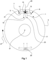
- figure 1 shows schematically an acceleration sensor 1 in an installed state on a vehicle wheel 3.
- the acceleration sensor 1 is part of an in 6 shown arrangement 601 for detecting a loss of grip of the vehicle wheel 3.
- the acceleration sensor 1 has a tube 5 with a longitudinal axis that forms a circular arc segment.
- the tube 5 has closed ends 7 and 9 .
- a contact surface 11 or 13 which faces the interior of the tube 5 , is arranged at each of the ends 7 and 9 .
- the tube 5 is filled with a fluid, not shown.
- a coil 17 surrounds the tube 5 by means of a coil wire 19 running around the tube several times.
- the coil 17 is supplied with current via two electrical contacts 21 and 23 in order to exert an attractive magnetic force on the ball 15 to exercise and to counteract a movement of the ball 15 in the direction of rotation 27 of the vehicle wheel 3 from a rest position 25 .
- the control unit 603 shown controls a power supply 613 of the coil 17.
- a positive acceleration of the vehicle wheel 3 in the direction of rotation 27 by a vehicle engine is taken into account. Ie when the vehicle wheel 3 is accelerated in the direction of rotation 27 by an increase in torque of the vehicle engine, the control unit 603 causes the coil to exert an increased force on the ball 15 so that it remains in the rest position 25 (unless other acceleration effects occur).
- a negative acceleration of the vehicle wheel 3 against the direction of rotation 27 by a vehicle brake is taken into account. That is to say, when the vehicle wheel 3 is decelerated by the vehicle brakes counter to the direction of rotation 27 , the control unit 603 causes the coil to exert an increased force on the ball 15 so that it remains in the rest position 25 .
- a loss of adhesion of the vehicle wheel 3 can be read from a movement of the ball 15 from the rest position 25 . If the vehicle wheel 3 spins, for example due to a loss of adhesion, the ball 15 moves in the viewing direction of FIG 1 Seen to the left from the rest position 25 out. If the vehicle wheel 3 blocks due to a loss of adhesion when braking the vehicle, the ball 15 moves in the viewing direction 1 seen to the right.
- a second duplex acceleration sensor 29 is arranged in vehicle wheel 3, which is functionally identical to first acceleration sensor 1.
- the second acceleration sensor 29 is arranged opposite the acceleration sensor 1 in relation to the center point 31 of the circular arc section. In other words: the second acceleration sensor 29 is offset by 180° in the direction of rotation 27 in relation to the first acceleration sensor 1 .
- the readout unit 608 comprises the 1 contact surfaces 11 and 13 shown. Communication between the evaluation electronics 607 and the readout unit 608 takes place wirelessly.
- the readout unit 608 detects when the ball 15 comes into contact with one of the contact surfaces 11 or 13 . A physical contact of the ball 15 with one of the contact surfaces 11 or 13 represents a loss of adhesion. This loss of liability is optically displayed to a vehicle driver 609 by means of a display 611 .
- the control unit 603 communicates wirelessly with the power supply 613 to control the force that the coil 17 exerts on the ball 15 .
- An actuating element 617 in the form of a button is arranged on a vehicle steering wheel 615 .
- an acceleration signal is sent to a control unit 619 .
- the control unit 619 is designed to control the vehicle engine and/or the vehicle brake in order to exert a positive or negative acceleration on the vehicle wheel 3 .
- a first method step A an acceleration sensor 1 arranged on the vehicle wheel 3 is used to test at regular time intervals whether there is a loss of adhesion. As soon as a loss of adhesion is detected, this loss of adhesion is verified in a method step B.
- the loss of adhesion is verified by the following steps: In a first method step i. the vehicle wheel 3 is accelerated by means of the vehicle brake and/or the vehicle engine. The acceleration is brought about by means of the control unit 619. In a further method step ii. the acceleration sensor 1 detects whether there is a loss of adhesion during acceleration.
- a method step C the vehicle driver 609 is informed about the verified loss of liability by means of the display 611 .
- the arrangement shown can also be used to carry out a second exemplary embodiment of a method according to the invention for detecting a loss of adhesion of the vehicle wheel 3 according to a third aspect of the invention.
- a first method step AA the actuating element 617 is actuated by the vehicle driver 609 .
- the actuation element 617 sends an acceleration signal to the control unit 619, which causes the vehicle wheel 3 to accelerate.
- a method step BB the vehicle wheel 3 is accelerated by means of the vehicle brake and/or by means of the vehicle engine.
- a loss of grip of the vehicle wheel 3 is detected by means of the acceleration sensor 1 in a method step CC.
- the acceleration according to the method step BB takes place through several successive accelerations of increasing intensity.
- the vehicle wheel is slightly accelerated. If no loss of grip is detected with this slight acceleration is, the vehicle wheel is again accelerated with an increased intensity.
- the intensity of the acceleration is increased with each new acceleration until a loss of grip is detected.
- a degree of grip can be determined using empirical values.
- the degree of adhesion can be displayed to the vehicle driver 609 in a method step DD using the display 611 .
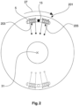
- FIG 2 shows schematically an acceleration sensor 201 in an installed state on a vehicle wheel 3.
- the acceleration sensor 201 is similar to that in FIG 1 Acceleration sensor 1 shown constructed. Identical and functionally identical elements are provided with the same reference symbols.
- the acceleration sensor 201 has two coils 203 and 205, each of which exerts a repulsive magnetic force on the ball 15 in order to counteract a movement of the ball 15 from the rest position.
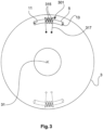
- FIG 3 shows schematically an acceleration sensor 301 in an installed state in a vehicle wheel 3.
- the acceleration sensor 301 is similar to that in FIG 1 Acceleration sensor 1 shown constructed. Identical and functionally identical elements are provided with the same reference symbols.
- In contrast to the in 1 Acceleration sensor 1 shown has acceleration sensor 301 a plurality of balls 315 .
- the coil 317 exerts an attractive force on the balls 315 to resist movement of the balls 315 from a rest position 25 .
- the acceleration sensor 401 has a chamber 403 in which a stock anchor-shaped mass 405 with a straight rod 407 and a circular arc-shaped section 409 is suspended.
- the suspension is at a first end of the rod 407, with the arcuate section 409 extending from a second end of the rod in two directions transverse to the longitudinal axis of the rod 407.
- a spiral spring 411 or 413 forms a connection between the rod 407 and an inner wall 415 or 417. The spiral springs 411 and 413 counteract the mass 405 pivoting out of a rest position 425.
- the chamber 403 has in each case a contact surface 419 or 421 with which one end 427 or 429 of the section 409 comes into contact when the mass 405 pivots out of the rest position 425 .
- This contact of an end 427 or 429 on a contact surface 419 or 421 is detected by means of a readout unit (not shown).
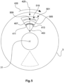
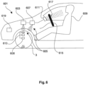
- FIG 5 shows schematically an acceleration sensor 501 in an installed state on a vehicle wheel 3.
- the acceleration sensor 501 is constructed similarly to the acceleration sensor 401. Identical and functionally identical elements are provided with the same reference symbols.
- the acceleration sensor 401 shown consists of the mass 505, which is arranged in a pendulum-like manner within the chamber 403, of a rod 407 and a spherical head mass 509.
- the rod 407 is pivotably suspended at a first end.
- the head mass 509 is located at a second end of the rod.
- acceleration sensor 501 has a plurality of contact surfaces 519 .
- the spherical mass 509 comes into contact with one of several contact surfaces 519.
- a readout unit detects which of the contact surfaces 519 the ball 509 is in contact with. The degree of deflection of the mass from the rest position 425 is thereby determined.
Description
Die Erfindung betrifft eine Anordnung sowie ein Verfahren zum Detektieren eines, insbesondere longitudinalen, Haftungsverlusts eines Fahrzeugrades.The invention relates to an arrangement and a method for detecting a loss of grip, in particular a longitudinal loss, of a vehicle wheel.
Unter dem Begriff Fahrzeugrad ist im Rahmen der vorliegenden Erfindung eine Felge mit einem Reifen zu verstehen, wobei der Reifen einen Kontakt mit der Fahrbahn herstellt, auf der sich das Fahrzeug bewegt. Unter einem Fahrzeug wird hier insbesondere ein Personenkraftwagen (PKW) verstanden. Der Begriff "Haftungsverlust" ist derart zu verstehen, dass der Reifen rutscht oder zumindest teilweise durchdreht. D.h. bei idealer Haftung entspricht die Rotationsgeschwindigkeit des Reifens der Geschwindigkeit des Fahrzeugs auf der Fahrbahn (*für Motorsportzwecke liegt die ideale Haftung bei 10-20 % Schlupf). Bei einem Haftungsverlust entsteht (kurzzeitig oder für einen längeren Zeitraum) eine Differenz zwischen Rotationsgeschwindigkeit des Reifens und der Geschwindigkeit des Fahrzeugs auf der Fahrbahn.In the context of the present invention, the term vehicle wheel is to be understood as meaning a rim with a tire, the tire making contact with the roadway on which the vehicle is moving. A vehicle is understood here in particular as a passenger car. The term "loss of grip" is to be understood as meaning that the tire slips or at least partially spins. This means that with ideal grip, the rotational speed of the tire corresponds to the speed of the vehicle on the road (*for motorsport purposes, the ideal grip is 10-20% slip). When there is a loss of grip, there is a difference (temporarily or for a longer period) between the rotational speed of the tire and the speed of the vehicle on the road.
Indirekte Beschleunigungssensoren, Rechenschaltungen, Anordnungen und Verfahren zum näherungsweisen Detektieren sind aus dem Stand der Technik grundsätzlich bekannt. Aus der
So sind, insbesondere indirekte, Beschleunigungssensoren an sich beispielsweise bekannt aus der
Ferner ist aus der
Vor diesem Hintergrund ist es Aufgabe der Erfindung, eine Anordnung und ein Verfahren zum Detektieren eines Haftungsverlusts eines Fahrzeugrades zu schaffen, insbesondere eine Detektion eines Haftungsverlusts zu erzielen, bevor das Fahrzeug, insbesondere das ganze Fahrzeug, ein stabiles Fahrverhalten verlässt.Against this background, the object of the invention is to create an arrangement and a method for detecting a loss of grip of a vehicle wheel, in particular to detect a loss of grip before the vehicle, in particular the entire vehicle, loses stable driving behavior.
Soweit die die hierin beschriebenen Ausführungen einen Beschleunigungssensor betreffen, dienen diese insbesondere der Veranschaulichung des/der Beschleunigungssensors/en der erfindungsgemäßen Anordnung und des erfindungsgemäßen Verfahrens zum Detektieren eines Haftungsverlustes eines Fahrzeugrades.Insofar as the embodiments described herein relate to an acceleration sensor, they serve in particular to illustrate the acceleration sensor(s) of the arrangement according to the invention and the method according to the invention for detecting a loss of adhesion of a vehicle wheel.
Zur Lösung dieser Aufgabe kann ein Beschleunigungssensor vorgesehen werden, der Beschleunigungssensor umfassend einen Tubus, mit einer Längsachse, die einen Kreisbogenabschnitt bildet, und mit zwei geschlossenen Enden, eine Masse, die innerhalb des Tubus und in Längsrichtung des Tubus beweglich angeordnet ist, eine Magnetanordnung, welche ausgebildet ist, mittels einer auf die Masse ausgeübten magnetischen Kraft einer Bewegung der Masse aus einer Ruheposition entgegenzuwirken, und eine Ausleseeinheit, welche ausgebildet ist, eine Bewegung der Masse aus der Ruheposition zu detektieren, wobei vorzugsweise der Tubus derart am Fahrzeugrad angeordnet ist, dass eine Bewegung der Masse aus der Ruheposition dann erfolgt, wenn sich die Beschleunigung des Fahrzeugrades (in Drehrichtung des Fahrzeugrades) ändert.To solve this problem, an acceleration sensor can be provided, the acceleration sensor comprising a tube, with a longitudinal axis that forms a circular arc section, and with two closed ends, a mass that is movably arranged inside the tube and in the longitudinal direction of the tube, a magnet arrangement, which is designed to counteract a movement of the mass from a rest position by means of a magnetic force exerted on the mass, and a readout unit which is designed to detect a movement of the mass from the rest position, with the tube preferably being arranged on the vehicle wheel in such a way that a movement of the mass from the rest position occurs when the acceleration of the vehicle wheel (in the direction of rotation of the vehicle wheel) changes.
Der Erfindung liegt die Erkenntnis zugrunde, dass bekannte Unfallvermeidungs- und Fahrdynamiksysteme, wie beispielsweise ESC (Electronic Stability Control; häufig auch als ESP bezeichnet), erst spät eingreifen, nämlich dann, wenn das gesamte Fahrzeug bereits eine stabile Fahrsituation weitgehend verlassen hat. Zudem erfolgt das Eingreifen dann vollständig durch das Fahrzeug. Das unfallvermeidende Potential eines Fahrzeugführers, also seine eigentlich immer anzunehmende Bereitschaft zur Mitverantwortung, wird dabei in der Vorphase nicht genutzt. Besonders auffällig wird dies bei Massenkollisionen infolge von Starkregen, Schneefall und/oder Eisbildung aber auch bei Individualunfällen aufgrund eines geringen Reifenprofils oder unangemessener Reifenspezifikation (Sommerreifen im Winter) oder Verlust des Anpressdrucks aufgrund mangelnder Aerodynamik bei hoher Geschwindigkeit. Bei den vorstehend genannten Fahrsituationen tritt im Ergebnis jeweils ein signifikanter Verlust der Haftung der Fahrzeugräder auf, welcher dem Fahrzeugführer in diesem Ausmaß bis zu seinem Unfall nicht bewusst ist. Würde man den Fahrzeugführer frühzeitig über den, sich im Allgemeinen ankündigenden und beginnenden, Haftungsverlust informieren, könnte dieser sofort reagieren und selbständig zur eigenen Unfallvermeidung beitragen.The invention is based on the finding that known accident avoidance and driving dynamics systems, such as ESC (Electronic Stability Control; often also referred to as ESP), only intervene late, namely when the entire vehicle has already largely left a stable driving situation. In addition, intervention is then carried out entirely by the vehicle. The accident-avoiding potential of a vehicle driver, i.e. his willingness to share responsibility, which can actually always be assumed, is not used in the preliminary phase. This is particularly noticeable in mass collisions as a result of heavy rain, snowfall and/or ice formation, but also in individual accidents due to a low tire profile or inappropriate tire specifications (summer tires in winter) or loss of contact pressure due to a lack of aerodynamics at high speeds. In the driving situations mentioned above, the result is a significant loss of grip of the vehicle wheels, which the vehicle driver was not aware of to this extent until his accident. If the vehicle driver were informed early on about the loss of liability that is generally announced and beginning, he could react immediately and independently contribute to his own accident avoidance.
Es wurde mit der Erfindung weiter erkannt, dass ein signifikanter Haftungsverlust durch Wasser-, Schnee-, Eisglätte sowie mangelndem Anpressdruck nicht blitzartig vollständig erfolgt. Stattdessen kündigt sich der Haftungsverlust in der Regel nur an einzelnen Reifen bereits in einer Vorphase an, ohne dass es für den Fahrzeugführer oder durch aus dem Stand der Technik bekannte Assistenzsysteme (z.B. ESC) erkannt wird, da es zu Beginn des Haftungsverlusts noch zu keinem Verlust an Fahrstabilität kommt. Bei den im Stand der Technik bekannten Systemen reagieren daher weder die Drehraten- und Querbeschleunigungssensoren des ESC noch die Propriozeption (d.h. die subjektive Eigenwahrnehmung) des Fahrzeugführers.It was also recognized with the invention that a significant loss of adhesion due to slippery water, snow, ice and a lack of contact pressure does not occur completely in a flash. Instead, the loss of grip usually only becomes apparent on individual tires in a preliminary phase, without it being a problem for the driver or for the driver Prior art known assistance systems (eg ESC) is recognized, since there is no loss of driving stability at the beginning of the loss of adhesion. In the systems known from the prior art, therefore, neither the yaw rate and lateral acceleration sensors of the ESC nor the proprioception (ie the subjective self-perception) of the vehicle driver react.
Insbesondere Wasserglätte tritt nicht in Form von einer blitzartigen, mehrere Millimeter dicken und geschlossenen Wasserdecke auf, die einen Reifen sofort und vollständig aufschwimmen lässt, sondern beginnt bei einsetzendem Regen sowie beim Einfahren in eine schon länger bestehende Regenzone mit einem gefleckten Übergangsbereich ("spotted area"). Auch verschneite oder vereiste Fahrbahnen sind nicht abrupt durchgängig glatt, sondern meist nur in einem relativ schmalen Temperaturband. Auch dieser Übergang geschieht für das Fahrzeug nicht blitzartig, sondern meist mit einem gefleckten Übergangsbereich. Schließlich erfolgt der Verlust von Anpressdruck bei zunehmender Geschwindigkeit ebenfalls nicht schlagartig, sondern beginnt aufgrund von stets vorhandenen Fahrbahnunebenheiten mit vereinzeltem "Tanzen" eines Reifens. In allen drei vorstehend genannten Situationen kommt es in der Übergangsphase zunächst an einzelnen Rädern zu, u.U. nur sehr kurzfristigem, inadäquatem Drehverhalten. Entweder drehen die einzelnen (Antriebs-) Räder zu schnell (kurzfristiges "Mkro-Durchdrehen") oder zu langsam (kurzfristiges "Mikro-Blockieren"), insbesondere beim Bremsen oder Schleppmoment. Mit anderen Worten: Es treten, kurze, insbesondere ultrakurze Dreh(zahl)schwankungen, insbesondere am einzelnen Rad, auf, die mittels der aus dem Stand der Technik bekannten Systeme nicht oder nur unzureichend detektiert werden.In particular, slippery water does not occur in the form of a lightning-fast, several millimeters thick and closed layer of water that immediately and completely floats a tire, but begins with the onset of rain or when entering a rain zone that has been there for some time with a spotted transition area ("spotted area"). ). Even snow-covered or icy roads are not suddenly completely smooth, but usually only in a relatively narrow temperature range. This transition also does not happen in a flash for the vehicle, but mostly with a spotted transition area. After all, the loss of contact pressure with increasing speed does not occur suddenly either, but begins with occasional "dancing" of a tire due to the always present bumps in the road surface. In all three of the situations mentioned above, individual wheels initially turn in the transitional phase, possibly only for a very short, inadequate turning behavior. Either the individual (drive) wheels are spinning too fast (temporary "micro-spin") or too slowly (temporary "micro-locking"), especially under braking or drag torque. In other words: Short, in particular ultra-short, rotational (speed) fluctuations occur, in particular on the individual wheel, which are not detected or are only insufficiently detected using the systems known from the prior art.
Diese und andere Probleme werden durch den Beschleunigungssensor gelöst bzw. reduziert, welcher eine hohe und gleichzeitig geschwindigkeitsunabhängige Empfindlichkeit auch bei hohen Geschwindigkeiten des Fahrzeugs aufweist. Der direkte Beschleunigungssensor weist eine hohe und nahezu gleichbleibend geschwindigkeitsunabhängige Empfindlichkeit auch bei den entscheidend hohen Geschwindigkeiten des Fahrzeugs auf im Gegensatz zu den vorbekannten indirekten Systemen, wie sie beispielsweise auf Seite 22, Zeilen 15ff. der
Neben der Unfallvermeidung kann der Beschleunigungssensor auch zur Feinabstimmung für den Motorsport verwendet werden (es lässt sich beispielsweise exakt ein gewünschter Schlupf einstellen) und die aus dem Stand der Technik bekannten Raddrehzahlsensoren für ESC ergänzen oder auch komplett ersetzen.In addition to accident prevention, the acceleration sensor can also be used for fine-tuning for motor sports (for example, a desired slip can be set exactly) and can supplement or even completely replace the wheel speed sensors known from the prior art for ESC.
Der Tubus ist vorzugsweise derart am Fahrzeugrad angeordnet, dass eine Bewegung der Masse aus der Ruheposition dann erfolgt, wenn sich die Beschleunigung des Fahrzeugrades, insbesondere in Drehrichtung des Fahrzeugrades, ändert. Auf diese Weise detektiert der Beschleunigungssensor über die Trägheit der Masse direkt eine Veränderung der Beschleunigung des Fahrzeugrades, was einen, insbesondere longitudinalen, Haftungsverlust bedeuten kann. Insbesondere, wenn das Fahrzeug nicht beschleunigt oder abgebremst wird, sollte ohne Haftungsverlust keine Veränderung der Beschleunigung des Fahrzeugrades eintreten. Ist dies doch der Fall, kann dies auf einen Haftungsverlust des Fahrzeugrades hindeuten, was durch den Beschleunigungssensor direkt detektiert werden kann, insbesondere ohne dass ein oder mehrere Sensorsignale zuvor ausgewertet oder weiterverarbeitet werden müssten.The tube is preferably arranged on the vehicle wheel in such a way that the mass moves out of the rest position when the acceleration of the vehicle wheel changes, in particular in the direction of rotation of the vehicle wheel. In this way, the acceleration sensor directly detects a change in the acceleration of the vehicle wheel via the inertia of the mass, which can mean a loss of adhesion, in particular a longitudinal loss. In particular, if the vehicle is not being accelerated or braked, there should be no change in the acceleration of the vehicle wheel without loss of grip. If this is the case, this can indicate a loss of grip of the vehicle wheel, which can be detected directly by the acceleration sensor, in particular without one or more sensor signals having to be evaluated or further processed beforehand.
Die Erfindung beruht unter anderem auf der Erkenntnis, dass existierende Sensoren oder Systeme zur Ermittlung des Radschlupfes insbesondere auch deshalb ungenau, fehleranfällig und/oder langsam sind, da
- a. die Änderung der Beschleunigung eines einzelnen Rades nicht direkt und unmittelbar detektiert und zur Anzeige gebracht wird, sondern indirekt über eine Auswertung oder Ableitung anderer Signale oder eine Berechnung aus anderen Signalen. Der Sensor ermittelt jedoch die den Haftungsverlust anzeigende Beschleunigungsänderung eines einzelnen Rades als Trägheitssensor direkt und unmittelbar;
- b. die entscheidend gefährlichen Haftungsverlustsituationen sich im hohen Geschwindigkeitsbereich (80-200 km/h) abspielen, wenn ultrakurzes inadäquates Drehverhalten einzelner Räder im höheren Grundrauschen einfach untergeht, wie beispielsweise in der
DE 32 06 694 A1 - c. auch ESP in diesem Geschwindigkeitsbereich bei meist vollständigem Haftungsverlust leider keinen wirksamen Effekt mehr aufbauen kann.
- a. the change in the acceleration of an individual wheel is not directly and immediately detected and displayed, but indirectly via an evaluation or derivation of other signals or a calculation from other signals. However, as an inertial sensor, the sensor determines the change in acceleration of an individual wheel, which indicates the loss of grip, directly and immediately;
- b. the decisively dangerous situations where there is a loss of grip take place in the high speed range (80-200 km/h) when ultra-short, inadequate turning behavior of individual wheels is simply lost in the higher background noise, such as in the
DE 32 06 694 A1 - c. Unfortunately, even ESP can no longer build up an effective effect in this speed range with mostly complete loss of adhesion.
Der Beschleunigungssensor ist im Einbauzustand vorzugsweise an oder in einem rotierenden Teil des Fahrzeugrads angeordnet, insbesondere an oder in einem Reifen, einer Felge oder einer Bremsscheibe. Weiter vorzugsweise erstreckt sich der Tubus im Einbauzustand im Wesentlichen über einen Kreisbogenabschnitt in Rotationsrichtung des Fahrzeugrades. Der Radius des Kreisbogenabschnitts entspricht dabei bevorzugt dem Radius des Fahrzeugrades an der Einbauposition, d.h. dem Abstand des Tubus vom Mittelpunkt des Fahrzeugrades, oder kleiner, wenn zur Hemmung keine anderen Bauteile eingesetzt werden sollen. Wird der Beschleunigungssensor beispielsweise im äußeren Bereich des Reifens eingebaut, entspricht der Radius des Kreisbogenabschnitts etwa dem Außenradius des Reifens. Die Bewegung der Masse in Längsrichtung entspricht vorzugsweise einer Bewegung entlang der Längsachse des Kreisbogenabschnitts und somit einer Bewegung in oder entgegen der Rotationsrichtung des Fahrzeugrades.In the installed state, the acceleration sensor is preferably arranged on or in a rotating part of the vehicle wheel, in particular on or in a tire, a rim or a brake disc. More preferably, the tube extends in the installed state essentially over a circular arc section in the direction of rotation of the vehicle wheel. The radius of the circular arc section preferably corresponds to the radius of the vehicle wheel at the installation position, i.e. the distance of the tube from the center of the vehicle wheel, or smaller if no other components are to be used for the escapement. If the acceleration sensor is installed, for example, in the outer area of the tire, the radius of the circular arc section corresponds approximately to the outer radius of the tire. The movement of the mass in the longitudinal direction preferably corresponds to a movement along the longitudinal axis of the circular arc section and thus to a movement in or against the direction of rotation of the vehicle wheel.
Weiter vorzugsweise ist der Tubus im Wesentlichen holzylinderförmig und geschlossen ausgebildet. Bevorzugt besteht der Tubus aus Kunststoff, insbesondere aus einem gehärteten Kunststoff, Keramik oder nicht-ferromagnetischem Metall. Dadurch kann der Beschleunigungssensor mechanischen Belastungen standhalten. Zudem kann der Beschleunigungssensor geschlossen von Kunststoff umgeben sein (z.B. in Kunststoff gegossen sein). Dadurch wird der Beschleunigungssensor widerstandsfähig beispielsweise gegenüber Schmutz, Flüssigkeit und Staub. Die Masse ist vorzugsweise kugelförmig ausgebildet. Dadurch wird der Verschleiß des Beschleunigungssensors minimiert. So kann ein Beschleunigungssensor über einen gesamten Wartungszyklus, vorzugsweise einen gesamten Lebenszyklus eines Fahrzeugs verwendet werden. Ein Beschleunigungssensor, welcher in einem Reifen eines Fahrzeugs eingebaut ist, wird beim Reifenwechsel ohne Zusatzaufwand mit ausgetauscht. So reicht es bereits aus, wenn der Beschleunigungssensor eine Lebensdauer aufweist, die einem Lebenszyklus eines Reifens entspricht. Weiter vorzugsweise besteht die Masse aus einem ferromagnetischen Material und/oder bildet einen Permanentmagneten.More preferably, the tube is essentially in the form of a hollow cylinder and is closed. The tube is preferably made of plastic, in particular a hardened plastic, ceramic or non-ferromagnetic metal. This allows the acceleration sensor to withstand mechanical loads. In addition, the acceleration sensor can be completely surrounded by plastic (e.g. cast in plastic). This makes the acceleration sensor resistant to dirt, liquid and dust, for example. The mass is preferably spherical. This minimizes the wear and tear on the acceleration sensor. An acceleration sensor can thus be used over an entire maintenance cycle, preferably an entire life cycle of a vehicle. An acceleration sensor, which is installed in a tire of a vehicle, is replaced when the tire is changed without any additional effort. It is already sufficient if the acceleration sensor has a service life that corresponds to the life cycle of a tire. More preferably, the mass consists of a ferromagnetic material and/or forms a permanent magnet.
Besonders bevorzugt ist der Beschleunigungssensor im Bereich der Radnabe, der Achse oder nahe dem Differential angeordnet. In diesen Bereichen des Fahrzeugrades ist der Beschleunigungssensor geschützt vor thermischen und mechanischen Belastungen, wie sie beispielsweise im Reifen oder im Bereich der Bremsscheiben auftreten können.The acceleration sensor is particularly preferably arranged in the area of the wheel hub, the axle or near the differential. In these areas of the vehicle wheel, the acceleration sensor is protected from thermal and mechanical loads, such as those that can occur in the tires or in the area of the brake discs.
Weiter vorzugsweise ist der Durchmesser des Tubus wesentlich kleiner als der Radius der Längsachse. Bevorzugt ist ein Verhältnis Durchmesser/Radius im Bereich von 1/400 (beispielsweise mit einem Tubusdurchmesser von 2 mm und einem Reifendurchmesser von 800 mm bei einer mobilen Arbeitsmaschine) bis maximal 1/40 (mit einem Tubusdurchmesser von 10 mm und einem Reifendurchmesser von 400 mm bei einem PKW), insbesondere bei PKWs in einem Bereich von 1/275 (z.B. mit einem Tubusdurchmesser von 2 mm und einem Reifendurchmesser von 550 mm) bis 1/40 (mit einem Tubusdurchmesser von 10 mm und einem Reifendurchmesser von 400 mm). Der Tubus weist bevorzugt eine Länge von wenigen Zentimetern auf. Besonders bevorzugt ist ein Längenverhältnis Durchmesser/Länge des Tubus im Bereich von 1/20 (mit einem Tubusdurchmesser von 2 mm und einer Länge des Tubus von 40 mm) bis 1/6 (mit einem Tubusdurchmesser von 5 mm und einer Länge des Tubus von 30 mm). Bei Verwendung einer kugelförmigen Masse liegt das Verhältnis des Durchmessers der Masse zum Durchmesser des Tubus vorzugsweise in einem Bereich von 1/2 bis 3/4. Besonders bevorzugt ist der Durchmesser der Masse geringfügig kleiner als der Innendurchmesser des Tubus, insbesondere mit einem Verhältnis Massendurchmesser/Innendurchmesser im Bereich von 7/8 bis 9/10, vorzugsweise auch bis zu 95/100. Dadurch werden Bewegungen der Masse quer zur Längsrichtung des Tubus, beispielswiese tanzende Bewegungen in Antwort auf eine Zentrifugalkraft oder Resonanzen in Antwort auf periodisch auf die Masse wirkende Kräfte, verringert.More preferably, the diameter of the tube is significantly smaller than the radius of the longitudinal axis. A diameter/radius ratio in the range of 1/400 is preferred (e.g. with a tube diameter of 2 mm and a tire diameter from 800 mm for a mobile work machine) up to a maximum of 1/40 (with a tube diameter of 10 mm and a tire diameter of 400 mm for a car), especially for cars in a range of 1/275 (e.g. with a tube diameter of 2 mm and a tire diameter of 550 mm) to 1/40 (with a tube diameter of 10 mm and a tire diameter of 400 mm). The tube preferably has a length of a few centimeters. A diameter/length ratio of the tube in the range from 1/20 (with a tube diameter of 2 mm and a tube length of 40 mm) to 1/6 (with a tube diameter of 5 mm and a tube length of 30 mm). When using a spherical mass, the ratio of the diameter of the mass to the diameter of the tube is preferably in a range from 1/2 to 3/4. The diameter of the mass is particularly preferably slightly smaller than the inner diameter of the tube, in particular with a mass diameter/inner diameter ratio in the range from 7/8 to 9/10, preferably also up to 95/100. This reduces movements of the mass transversely to the longitudinal direction of the tube, for example dancing movements in response to a centrifugal force or resonances in response to forces acting periodically on the mass.
Gemäß einer ersten bevorzugten Ausführungsform des Beschleunigungssensors umfasst die Magnetanordnung eine den Tubus zumindest teilweise umgebende elektrische Spulenanordnung, insbesondere Kreisbogenspule. Vorzugsweise wird die Magnetanordnung von einer Spulenanordnung gebildet, welche aus einem den Tubus mehrfach umlaufenden Draht besteht. Damit die Spulenanordnung eine magnetische Kraft auf die Masse ausübt, wird der Spulendraht mit elektrischem Strom versorgt. Der Begriff Kreisbogenspule ist bevorzugt derart zu verstehen, dass die Spule um den kreisbogenartig verlaufenden Tubus gewickelt ist und somit quer zur Umlaufrichtung des Drahtes kreisbogenartig verläuft. Vorzugsweise erfolgt die Spannungsversorgung der Spule mittels Induktion oder mittels einer Batterie.According to a first preferred embodiment of the acceleration sensor, the magnet arrangement comprises an electrical coil arrangement, in particular a circular arc coil, at least partially surrounding the tube. The magnet arrangement is preferably formed by a coil arrangement, which consists of a wire running around the tube several times. Electric current is supplied to the coil wire so that the coil arrangement exerts a magnetic force on the mass. The term circular arc coil is preferably to be understood in such a way that the coil is wound around the tube running in the manner of a circular arc and thus runs in the manner of a circular arc transversely to the direction of rotation of the wire. The coil is preferably supplied with voltage by means of induction or by means of a battery.
Gemäß einer weiteren bevorzugten Ausführungsform des Beschleunigungssensors umfasst die Magnetanordnung einen Magnetabschnitt, welcher ausgebildet ist, eine anziehende Kraft auf die Masse auszuüben, wobei die Ruheposition der Masse in Rotationsrichtung des Fahrzeugrades innerhalb des Magnetabschnitts liegt. Der Magnetabschnitt wird vorzugsweise von einem Spulenabschnitt gebildet. Vorzugsweise umgibt der Spulenabschnitt einen mittleren Bereich der Längsachse des Tubus, wobei der mittlere Bereich den Tubus in zwei gleiche Hälften teilt. Eine Bewegung der Masse aus dem mittleren Bereich heraus stellt dabei eine Bewegung der Masse aus der Ruheposition dar.According to a further preferred embodiment of the acceleration sensor, the magnet arrangement comprises a magnet section which is designed to exert an attractive force on the mass, the rest position of the mass being within the magnet section in the direction of rotation of the vehicle wheel. The magnet section is preferably formed by a coil section. Preferably, the coil portion surrounds a central portion of the longitudinal axis of the tube, the central portion dividing the tube into two equal halves. A movement of the crowd from the middle range represents a movement of the mass from the rest position.
Nach einer anderen bevorzugten Ausführungsform des Beschleunigungssensors umfasst die Magnetanordnung zwei Magnetabschnitte, die ausgebildet sind, eine abstoßende Kraft auf die Masse auszuüben, wobei die Ruheposition der Masse in Rotationsrichtung des Fahrzeugrades zwischen den Magnetabschnitten liegt. Vorzugsweise werden die Magnetabschnitte jeweils von einem Spulenabschnitt gebildet. Die beiden Spulenabschnitte umgeben in Längsrichtung des Tubus gesehen vorzugsweise jeweils einen Endbereich des Tubus derart, dass die Masse aufgrund der abstoßenden Kräfte der Spulenabschnitte in einem mittleren Bereich des Tubus in einer Ruheposition gehalten wird.According to another preferred embodiment of the acceleration sensor, the magnet arrangement comprises two magnet sections which are designed to exert a repelling force on the mass, the rest position of the mass being between the magnet sections in the direction of rotation of the vehicle wheel. The magnet sections are preferably each formed by a coil section. Viewed in the longitudinal direction of the tube, the two coil sections preferably each surround an end region of the tube in such a way that the mass is held in a rest position in a central region of the tube due to the repelling forces of the coil sections.
Nach einer weiteren bevorzugten Ausführungsform des Beschleunigungssensors umfasst die Ausleseeinheit eine Kontaktfläche, die jeweils an einem Ende des Tubus angeordnet ist, wobei die Ausleseeinheit ausgebildet ist, einen Berührungskontakt der Masse an der Kontaktfläche zu detektieren. Dies stellt eine konstruktiv besonders einfache Ausbildung des Beschleunigungssensors dar, mittels derer die Bewegung der Masse aus der Ruheposition qualitativ detektiert werden kann. Der Beschleunigungssensor kann vorzugsweise derart dimensioniert sein, dass minimale Bewegungsschwankungen der Masse nicht zu einem Berührungskontakt an einer der Kontaktflächen führen.According to a further preferred embodiment of the acceleration sensor, the readout unit comprises a contact surface which is arranged at one end of the tube, the readout unit being designed to detect physical contact of the mass on the contact surface. This represents a structurally particularly simple design of the acceleration sensor, by means of which the movement of the mass from the rest position can be qualitatively detected. The acceleration sensor can preferably be dimensioned in such a way that minimal movement fluctuations of the mass do not lead to physical contact on one of the contact surfaces.
Gemäß einer weiteren bevorzugten Ausführungsform des Beschleunigungssensors ist die Ausleseeinheit ausgebildet, die Position der Masse innerhalb des Tubus zu ermitteln. Dies hat den Vorteil, dass anhand der Position der Masse bei Auslenkung aus der Ruhelage ein Grad der Haftung, beispielsweise der Reibungskoeffizient zwischen dem Material des Fahrzeugreifens und der Fahrbahn, ermittelt werden kann. Insbesondere im Motorsport kann eine quantitative Bestimmung des Haftungsgrades zu Optimierungszwecken genutzt werden.According to a further preferred embodiment of the acceleration sensor, the readout unit is designed to determine the position of the mass inside the tube. This has the advantage that a degree of adhesion, for example the coefficient of friction between the material of the vehicle tire and the roadway, can be determined based on the position of the mass when it is deflected from the rest position. Especially in motor sports, a quantitative determination of the degree of adhesion can be used for optimization purposes.
Vorzugsweise ist der Beschleunigungssensor ferner ausgebildet, nur solche Änderungen der Beschleunigung des Fahrzeugrades zu detektieren, die nicht auf einer gewollten Beschleunigung des Fahrzeugs (durch den Fahrzeugmotor) oder einem Bremsvorgang beruhen.The acceleration sensor is preferably also designed to only detect those changes in the acceleration of the vehicle wheel that are not based on a desired acceleration of the vehicle (by the vehicle engine) or on a braking process.
Der Beschleunigungssensor umfasst gemäß einer Fortbildung der oben beschriebenen ersten bevorzugten Ausführungsform eine Steuerungseinheit, welche ausgebildet ist, die mittels der Spulenanordnung auf die Masse ausgeübte Kraft in Abhängigkeit von der auf das Fahrzeugrad mittels der Fahrzeugbremsen und des Fahrzeugmotors ausgeübten Beschleunigung zu steuern. Im Betrieb wird ein Fahrzeug ständig beschleunigt und abgebremst. Diese Kräfte wirken auch auf den Beschleunigungssensor und können die Detektion eines Haftungsverlusts beeinflussen. Gemäß dieser Ausführungsform wird die Kraft, welche die Spulenanordnung auf die Masse ausübt, mittels einer Steuerungseinheit gesteuert. Die Steuerungseinheit berücksichtigt dabei die aktuelle Beschleunigung durch den Fahrzeugmotor und die aktuelle Bremsbeschleunigung durch die Fahrzeugbremsen. Weiter bevorzugt können weitere Effekte wie Motorbremswirkung, Reibungsverluste, Windeinfluss, etc. bei der Steuerung der Spule berücksichtigt werden. Die Steuerung der durch die Spule auf die Masse ausgeübten Kraft erfolgt über eine Steuerung des durch den Spulendraht fließenden Stroms.According to a further development of the first preferred embodiment described above, the acceleration sensor comprises a control unit which is designed to to control the force exerted on the mass by means of the coil arrangement as a function of the acceleration exerted on the vehicle wheel by means of the vehicle brakes and the vehicle engine. During operation, a vehicle is constantly being accelerated and braked. These forces also act on the acceleration sensor and can affect the detection of a loss of grip. According to this embodiment, the force that the coil arrangement exerts on the mass is controlled by a control unit. The control unit takes into account the current acceleration by the vehicle engine and the current deceleration by the vehicle brakes. More preferably, other effects such as engine braking effect, friction losses, wind influence, etc. can be taken into account when controlling the coil. The force exerted by the coil on the mass is controlled by controlling the current flowing through the coil wire.
Durch diese Ausführungsform wird ein Beschleunigungssensor geschaffen, welcher in einer Vielzahl von Fahrsituationen zuverlässigere Ergebnisse hinsichtlich eines Haftungsverlusts eines Fahrzeugrads bereitstellt. Dabei werden unterschiedliche Beschleunigungseffekte, die auf das Fahrzeugrad wirken, durch eine Steuerung der Spulenanordnung derart eliminiert bzw. reduziert, dass eine Auslenkung der Masse aus der Ruheposition in einer Vielzahl von Fahrsituationen als Haftungsverlust detektiert werden kann.This embodiment creates an acceleration sensor which provides more reliable results with regard to a loss of grip of a vehicle wheel in a large number of driving situations. Different acceleration effects that act on the vehicle wheel are eliminated or reduced by controlling the coil arrangement in such a way that a deflection of the mass from the rest position can be detected as a loss of adhesion in a large number of driving situations.
Die Ausführungsform des Beschleunigungssensors mit Steuerungseinheit hat ferner den Vorteil, dass für unterschiedliche Fahrzeugtypen Beschleunigungssensoren gleicher Abmessung und gleichen Materials verwendet werden können. Dies vereinfacht die Herstellung der Beschleunigungssensoren. Eine Anpassung des Beschleunigungssensors an den Fahrzeugtyp erfolgt vorzugsweise über die Steuerung. So können die Motorleistungen und Bremsleistungen unterschiedlicher Fahrzeugtypen bei der Steuerung berücksichtigt werden, beispielsweise indem die Steuerung beim Fahrzeughersteller oder bei Sportwagen im Fahrzeug selbst über ein Computerprogramm kalibriert wird.The embodiment of the acceleration sensor with a control unit also has the advantage that acceleration sensors of the same dimensions and the same material can be used for different vehicle types. This simplifies the manufacture of the acceleration sensors. The acceleration sensor is preferably adapted to the vehicle type via the controller. The engine power and braking power of different vehicle types can be taken into account in the control, for example by the control being calibrated by the vehicle manufacturer or in the vehicle itself using a computer program in the case of sports cars.
Insbesondere für eine Verwendung im Rahmen eines Feintunings, z.B. im Motorsport, ist die Anwendung der vergleichsweise aufwendigen Ausführungsform mit Steuerungseinheit besonders bevorzugt.In particular for use in the context of fine tuning, e.g. in motor sports, the use of the comparatively complex embodiment with a control unit is particularly preferred.
In einer weiteren bevorzugten Ausführungsform des Beschleunigungssensors ist der Tubus mit einem Fluid zur Dämpfung der Bewegung der Masse gefüllt. Bevorzugt umfasst das Fluid Luft, Wasser und/oder Öl. Gegebenenfalls kann auch ein innertubuläres Bypass-System vorgesehen sein.In a further preferred embodiment of the acceleration sensor, the tube is filled with a fluid to dampen the movement of the mass. The fluid preferably includes air, water and/or oil. If necessary, an innertubular bypass system can also be provided.
Der Beschleunigungssensor umfasst nach einer noch weiteren bevorzugten Ausführungsform mehrere Massen. Die Massen bestehen vorzugsweise jeweils aus einem ferromagnetischen Material und/oder bilden Permanentmagneten. Weiter vorzugsweise sind die Massen jeweils kugelförmig ausgebildet. Vorzugsweise liegt das Verhältnis des Durchmessers einer der kugelförmigen Massen zum Durchmesser des Tubus vorzugsweise in einem Bereich von 1/3 bis 1/10. Die Ausleseeinheit ist vorzugsweise ausgebildet, die Bewegung einer oder mehrerer der Massen aus der Ruheposition zu detektieren. Weiter vorzugsweise ist die Ausleseeinheit ausgebildet, die Position einer oder mehrerer Massen innerhalb des Tubus zu ermitteln. Noch weiter bevorzugt ist die Ausleseeinheit ausgebildet, die örtliche Verteilung der Massen innerhalb des Tubus zu ermitteln.According to yet another preferred embodiment, the acceleration sensor comprises a plurality of masses. The masses preferably each consist of a ferromagnetic material and/or form permanent magnets. More preferably, the masses are each spherical. Preferably, the ratio of the diameter of one of the spherical masses to the diameter of the tube is preferably in a range from 1/3 to 1/10. The readout unit is preferably designed to detect the movement of one or more of the masses from the rest position. More preferably, the readout unit is designed to determine the position of one or more masses inside the tube. Even more preferably, the readout unit is designed to determine the local distribution of the masses within the tube.
Zur Lösung der eingangs genannten Aufgabe kann auch ein Beschleunigungssensor zum Detektieren eines Haftungsverlusts eines Fahrzeugrades vorgesehen werden, der Beschleunigungssensor umfassend eine Masse, die entlang eines Kreisbogenabschnitts beweglich angeordnet ist, wenigstens ein Federelement, welches ausgebildet ist, einer Bewegung der Masse aus einer Ruheposition entgegenzuwirken, und eine Ausleseeinheit, welche ausgebildet ist, eine Bewegung der Masse aus der Ruheposition zu detektieren, wobei vorzugsweise die Masse derart am Fahrzeugrad angeordnet ist, dass eine Bewegung der Masse aus der Ruheposition erfolgt, wenn sich die Beschleunigung des Fahrzeugrades, vorzugsweise in Drehrichtung des Fahrzeugrades, ändert.To solve the task mentioned at the outset, an acceleration sensor for detecting a loss of adhesion of a vehicle wheel can also be provided, the acceleration sensor comprising a mass which is movably arranged along a circular arc section, at least one spring element which is designed to counteract a movement of the mass from a rest position, and a readout unit which is designed to detect a movement of the mass from the rest position, the mass preferably being arranged on the vehicle wheel in such a way that the mass moves from the rest position when the acceleration of the vehicle wheel changes, preferably in the direction of rotation of the vehicle wheel , changes.
Der Beschleunigungssensor ist im Einbauzustand vorzugsweise an oder in einem rotierenden Teil des Fahrzeugrads angeordnet, insbesondere an oder in einem Reifen, einer Felge oder einer Bremsscheibe. Weiter vorzugsweise erstreckt sich der Kreisbogenabschnitt, entlang dessen die Masse beweglich angeordnet ist, im Wesentlichen in Rotationsrichtung des Fahrzeugrades. Der Radius des Kreisbogenabschnitts entspricht dabei bevorzugt dem Radius des Fahrzeugrades an der Einbauposition, d.h. dem Abstand der Masse vom Mittelpunkt des Fahrzeugrades, oder kleiner, wenn zur Hemmung keine anderen Bauteile eingesetzt werden sollen.In the installed state, the acceleration sensor is preferably arranged on or in a rotating part of the vehicle wheel, in particular on or in a tire, a rim or a brake disk. More preferably, the circular arc section, along which the mass is movably arranged, extends essentially in the direction of rotation of the vehicle wheel. The radius of the circular arc section preferably corresponds to the radius of the vehicle wheel at the installation position, i.e. the distance of the mass from the center of the vehicle wheel, or smaller if no other components are to be used for the deceleration.
Die Masse ist vorzugsweise derart am Fahrzeugrad angeordnet, dass eine Bewegung der Masse aus der Ruheposition erfolgt, wenn sich die Beschleunigung des Fahrzeugrades, insbesondere in Drehrichtung des Fahrzeugrades, ändert. Auf diese Weise detektiert der Beschleunigungssensor über die Trägheit der Masse direkt eine Veränderung der Beschleunigung des Fahrzeugrades, was einen Haftungsverlust bedeuten kann. Insbesondere, wenn das Fahrzeug nicht beschleunigt oder abgebremst wird, sollte ohne Haftungsverlust keine Veränderung der Beschleunigung des Fahrzeugrades eintreten. Ist dies doch der Fall, kann dies auf einen Haftungsverlust des Fahrzeugrades hindeuten, was durch den Beschleunigungssensor direkt detektiert werden kann, insbesondere ohne dass ein oder mehrere Sensorsignale zuvor ausgewertet oder weiterverarbeitet werden müssten.The mass is preferably arranged on the vehicle wheel in such a way that the mass moves out of the rest position when the acceleration of the vehicle wheel changes, in particular in the direction of rotation of the vehicle wheel. In this way, the acceleration sensor directly detects a change in the acceleration of the vehicle wheel via the inertia of the mass, which can mean a loss of grip. In particular, if the vehicle is not being accelerated or braked, there should be no change in the acceleration of the vehicle wheel without loss of grip. Is If this is the case, this can indicate a loss of adhesion of the vehicle wheel, which can be detected directly by the acceleration sensor, in particular without one or more sensor signals having to be evaluated or processed beforehand.
Weiter vorzugsweise ist die bewegliche Masse in einer geschlossenen Kammer angeordnet, wobei zwei Federelemente die Masse mit einer Innenwandung der Kammer verbinden. Die Kammer besteht vorzugsweise aus geschlossenem und gehärtetem Kunststoff, Keramik oder Metall. Dadurch wird der Beschleunigungssensor widerstandsfähig beispielsweise gegenüber Schmutz, Flüssigkeit und Staub. So kann ein Beschleunigungssensor über einen gesamten Wartungszyklus, vorzugsweise einen gesamten Lebenszyklus eines Fahrzeugs verwendet werden. Ein Beschleunigungssensor, welcher in einem Reifen eines Fahrzeugs eingebaut ist, wird bei Reifenwechsel mit ausgetauscht. So reicht es bereits aus, wenn der Beschleunigungssensor eine Lebensdauer aufweist, die einem Lebenszyklus eines Reifens entspricht.More preferably, the movable mass is arranged in a closed chamber, with two spring elements connecting the mass to an inner wall of the chamber. The chamber is preferably made of closed and hardened plastic, ceramic or metal. This makes the acceleration sensor resistant to dirt, liquid and dust, for example. An acceleration sensor can thus be used over an entire maintenance cycle, preferably an entire life cycle of a vehicle. An acceleration sensor, which is built into a tire of a vehicle, is also replaced when the tire is changed. It is already sufficient if the acceleration sensor has a service life that corresponds to the life cycle of a tire.
Ein Vorteil des Beschleunigungssensors gemäß diesem Aspekt ist der konstruktiv besonders einfache Aufbau und eine kostengünstige Herstellung. Bei geringen Auslenkungen der Masse aus der Ruheposition entspricht die auf die Masse ausgeübte Kraft dem Hookeschen Gesetz. Dadurch ist eine quantitative Berechnung der auf die Masse ausgeübten Beschleunigung anhand der Auslenkung der Masse aus der Ruheposition besonders einfach.An advantage of the acceleration sensor according to this aspect is the structurally particularly simple design and inexpensive production. For small deflections of the mass from the rest position, the force exerted on the mass obeys Hooke's law. This makes it particularly easy to quantitatively calculate the acceleration exerted on the mass based on the deflection of the mass from the rest position.
Gemäß einer bevorzugten Ausführungsform des Beschleunigungssensors ist die Masse pendelartig an einem Mittelpunkt des Kreisbogenabschnitts befestigt. Dabei ist die Masse im Einbauzustand des Beschleunigungssensors vorzugsweise an oder in einem Fahrzeugrad angeordnet und im Wesentlichen in Rotationsrichtung des Fahrzeugrades auslenkbar. Die pendelartige Aufhängung der Masse ist vorzugsweise derart ausgebildet, dass der Aufhängepunkt innerhalb der Kammer liegt, in welcher die Masse angeordnet ist. Der Kreisbogenabschnitt weist dann einen Radius auf, der wesentlich kleiner als der Radius des Fahrzeugrades an der Einbauposition ist. Weiter bevorzugt ist die Masse im Wesentlichen stockankerförmig ausgebildet ist, nämlich mit einer geraden Stange, an deren Ende ein kreisbogenförmiger Abschnitt angeordnet ist.According to a preferred embodiment of the acceleration sensor, the mass is fastened like a pendulum at a center point of the circular arc section. When the acceleration sensor is installed, the mass is preferably arranged on or in a vehicle wheel and can be deflected essentially in the direction of rotation of the vehicle wheel. The pendulum-like suspension of the mass is preferably designed in such a way that the suspension point lies within the chamber in which the mass is arranged. The circular arc section then has a radius that is significantly smaller than the radius of the vehicle wheel at the installation position. More preferably, the mass is essentially in the form of a stock anchor, namely with a straight rod, at the end of which a section in the shape of a circular arc is arranged.
Nach einer weiteren bevorzugten Ausführungsform des Beschleunigungssensors umfasst die Ausleseeinheit eine Kontaktfläche und ist ausgebildet, einen Berührungskontakt der Masse an der Kontaktfläche zu detektieren. Insbesondere bei Verwendung einer stockankerförmigen Masse wird dadurch ein Beschleunigungssensor geschaffen, welcher bereits bei geringen Auslenkungen in Berührungskontakt mit einer Kontaktfläche gelangt. Denn der kreisbogenförmige Abschnitt schafft zwei Arme, die sich ausgehend von der geraden Stange in Auslenkungsrichtung erstrecken.According to a further preferred embodiment of the acceleration sensor, the readout unit comprises a contact surface and is designed to detect physical contact of the mass on the contact surface. Especially when using a stock anchor-shaped An acceleration sensor is thus created, which already comes into physical contact with a contact surface in the case of small deflections. This is because the arcuate section creates two arms which extend in the direction of deflection, starting from the straight rod.
In einer weiteren bevorzugten Ausführungsform des Beschleunigungssensors ist die Ausleseeinheit ausgebildet, eine Position der Masse in Rotationsrichtung des Fahrzeugrades zu ermitteln. Dadurch kann die auf die Masse ausgeübte Beschleunigung und somit der Haftungsgrad des Fahrzeugrades quantitativ ermittelt werden.In a further preferred embodiment of the acceleration sensor, the readout unit is designed to determine a position of the mass in the direction of rotation of the vehicle wheel. As a result, the acceleration exerted on the mass and thus the degree of adhesion of the vehicle wheel can be determined quantitatively.
Die eingangs genannte Aufgabe wird gemäß einem ersten Aspekt der Erfindung gelöst durch eine Anordnung zum Detektieren eines Haftungsverlusts eines Fahrzeugrades nach Anspruch 1. Die erfindungsgemäße Anordnung zum Detektieren eines Haftungsverlusts eines Fahrzeugrades umfasst einen ersten Beschleunigungssensor, insbesondere eines Beschleunigungssensors der oben beschriebenen Art, welcher an einem Fahrzeugrad angeordnet ist, eine Warneinheit, welche ausgebildet ist, bei Detektion eines Haftungsverlusts mittels des Beschleunigungssensors einen Fahrzeugführer über den Haftungsverlust zu informieren.The object mentioned at the outset is achieved according to a first aspect of the invention by an arrangement for detecting a loss of adhesion of a vehicle wheel according to
Die Warneinheit kann vorzugsweise eine Anzeige sein, die von dem Fahrzeugführer wahrnehmbar ist. Die Anzeige kann ein analoges Rundinstrument, eine Digital- oder Balkenanzeige an den Armaturen des Fahrzeugcockpits oder ein Head-Up-Display sein. Die Anzeige ist vorzugsweise ausgebildet, den Grad der Haftung in Prozent darzustellen (100% Haftung bis zum vollständigen Gleiten mit 0% Haftung). Weiter vorzugsweise umfasst die Warneinheit eine akustischen Warneinheit und/oder ein Lenkrad, welche(s) zur Warnung vibriert.The warning unit may preferably be a display perceivable by the vehicle driver. The display can be an analogue round instrument, a digital or bar graph on the dashboard of the vehicle or a head-up display. The display is preferably configured to show the degree of adhesion as a percentage (100% adhesion to full slip with 0% adhesion). More preferably, the warning unit comprises an acoustic warning unit and/or a steering wheel, which vibrates to warn.
Nach einer bevorzugten Ausführungsform der erfindungsgemäßen Anordnung ist ein zweiter (Duplex-) Beschleunigungssensor, insbesondere nach der oben beschriebenen Art, am Fahrzeugrad angeordnet, insbesondere bezogen auf einen Mittelpunkt des Kreisbogenabschnitts gegenüberliegend zum ersten Beschleunigungssensor. Dieser zweite Beschleunigungssensor bzw. die Ausführungsform mit dem zweiten Beschleunigungssensor kann auch als Duplex-Beschleunigungssensor bezeichnet werden. Mit anderen Worten: Der zweite (Duplex-) Beschleunigungssensor ist in Rotationsrichtung des Fahrzeugrades um 180° versetzt zum ersten Beschleunigungssensor angeordnet. Werden die Auslenkungen der Masse des ersten und zweiten Beschleunigungssensors in Laufrichtung gesehen in Summe betrachtet, heben sich lineare Beschleunigungen des Rades auf und Rotationsbeschleunigungen addieren sich. Dadurch können störende Effekte, die unabhängig von einem Haftungsverlust eines Fahrzeugrades auftreten, wie beispielsweise Unwuchten aber auch falschpositive Auslenkungen der Masse aufgrund einer linearen Beschleunigung des ganzen Rades (z.B. durch Schlaglöcher) herausgerechnet werden. Die erfindungsgemäße Anordnung umfasst eine Steuerungseinheit, welche ausgebildet ist, die Fahrzeugbremse und/oder den Fahrzeugmotor anzusteuern, um eine Test-Beschleunigung, wenigstens eines Fahrzeugrades zu bewirken. Die Steuerungseinheit hat den Zweck, Test-Beschleunigungen eines oder mehrerer der Fahrzeugräder (durch Bremsen oder Motorbeschleunigung) zu bewirken, um einen beginnenden Haftungsverlust geringer Intensität zu bewirken, welcher zur Ermittlung des Grades des Haftungsverlusts dient. So ist die Steuerungseinheit ausgebildet,
- a. in regelmäßigen zeitlichen Abständen Test-Beschleunigungen auf eines oder mehrere der Fahrzeugräder zu bewirken, insbesondere automatisch, in kritischen Fahrzuständen bei Ansprechen eines Regensensors oder unterhalb
von 3° Celsius. - b. Alternativ zu der vorstehend genannten Ausführungsform umfasst die erfindungsgemäße Anordnung ein Betätigungselement, welches ausgebildet ist, in verdächtigen Fahrsituationen (z.B. Regen und Tempo 160 km/h, wobei der Erfinder hier nicht seine Fahrweise wiedergibt und sich auch davon distanziert), bei Betätigung durch einen Fahrzeugführer ein Test-Beschleunigungssignal an die Steuerungseinheit zu senden, um eine Test-Beschleunigung wenigstens eines Fahrzeugrades zu bewirken. Das Betätigungselement ist als Taster ausgebildet, welcher an den Armaturen des Fahrzeugcockpits angeordnet ist und vom Fahrzeugführer betätigt werden kann, wenn er die Haftung eines oder mehrerer Fahrzeugräder auf der Fahrbahn testen möchte. Das Betätigungselement kann als manuelles Betätigungselement ausgebildet und/oder Teil der Steuerungseinheit sein.
- a. to effect test accelerations on one or more of the vehicle wheels at regular time intervals, in particular automatically, in critical driving conditions when a rain sensor responds or below 3° Celsius.
- b. As an alternative to the embodiment mentioned above, the arrangement according to the invention comprises an actuating element which is designed to act in suspicious driving situations (e.g. rain and a speed of 160 km/h, although the inventor does not describe his driving style here and also distances himself from it) when actuated by a vehicle driver to send a test acceleration signal to the control unit in order to effect a test acceleration of at least one vehicle wheel. The actuating element is designed as a button, which is arranged on the fittings of the vehicle cockpit and can be actuated by the vehicle driver if he wants to test the adhesion of one or more vehicle wheels on the road. The actuating element can be designed as a manual actuating element and/or be part of the control unit.
Die eingangs genannte Aufgabe wird gemäß einem zweiten Aspekt der Erfindung gelöst durch ein Verfahren zum Detektieren eines Haftungsverlusts eines Fahrzeugrades nach Anspruch 6. Das Verfahren gemäß dem zweiten Aspekt der Erfindung umfasst die Schritte:
- a) Verifizieren eines Haftungsverlusts eines Fahrzeugrades, wenn der Haftungsverlust mittels eines an dem Fahrzeugrad angeordneten Beschleunigungssensors, insbesondere eines Beschleunigungssensors der oben beschriebenen Art, in kritischen Fahrzuständen bei Ansprechen eines Regensensors oder unterhalb
von 3° Celsius detektiert wird, wobei das Verifizieren erfolgt durch- i. Beschleunigen des Fahrzeugrades mittels einer Fahrzeugbremse und/oder eines Fahrzeugmotors in regelmäßigen zeitlichen Abständen in kritischen Fahrzuständen bei Ansprechen eines Regensensors oder unterhalb
von 3° Celsius, - ii. Detektieren eines Haftungsverlustes während des Beschleunigens mittels des Beschleunigungssensors,
- i. Beschleunigen des Fahrzeugrades mittels einer Fahrzeugbremse und/oder eines Fahrzeugmotors in regelmäßigen zeitlichen Abständen in kritischen Fahrzuständen bei Ansprechen eines Regensensors oder unterhalb
- b) Informieren eines Fahrzeugführers über den verifizierten Haftungsverlust mittels einer Warneinheit.
- a) Verifying a loss of grip of a vehicle wheel if the loss of grip is detected by means of an acceleration sensor arranged on the vehicle wheel, in particular an acceleration sensor of the type described above, in critical driving states is detected when a rain sensor responds or below 3° Celsius, the verification being carried out by
- i. Accelerating the vehicle wheel using a vehicle brake and/or a vehicle engine at regular time intervals in critical driving conditions when a rain sensor responds or below 3° Celsius,
- ii. detecting a loss of grip during acceleration using the acceleration sensor,
- b) Informing a vehicle driver about the verified loss of liability by means of a warning unit.
Mit der Erfindung wurde erkannt, dass eine Verifikation eines detektierten Haftungsverlusts wünschenswert ist, insbesondere frühzeitig bei beginnenden Haftungsverlusten geringer Intensität, die noch keine Gefahr für das stabile Fahrverhalten darstellen. Das erfindungsgemäße Verfahren löst dieses Problem durch einen aktiven Test, bei dem eines oder mehrere Fahrzeugräder beschleunigt werden, um zu detektieren, ob ein erneuter Haftungsverlust auftritt. Die Beschleunigung erfolgt vorzugsweise durch einen Bremseingriff, eine abrupte Fahrzeugmotorbeschleunigung oder auch durch ein KERS (Kinetic Energy Recovery System). Initiiert wird die Beschleunigung vorzugsweise durch eine Steuerungseinheit der oben beschriebenen Art, welche ausgebildet ist, die Fahrzeugbremse und/oder den Fahrzeugmotor anzusteuern, um eine Beschleunigung wenigstens eines Fahrzeugrades zu bewirken. Weiter bevorzugt erfolgt die Beschleunigung an wenigstens zwei Rädern, die sich diagonal einander gegenüberstehen, beispielsweise das Rad vorne links und das Rad hinten rechts. Insbesondere bevorzugt erfolgt eine Kompensation des testbeschleunigten Rades an den übrigen 3 Rädern. Vorzugsweise erfährt das diagonal gegenüberliegende Rad eine Beschleunigung mit gleichem Vorzeichen und die beiden anderen Räder eine Beschleunigung mit entgegengesetzten Vorzeichen. Dadurch wird sowohl die Schleudergefahr beim Testen des Haftungsverlusts gemindert als auch die Beschleunigung des gesamten PKW gemindert oder verhindert.With the invention, it was recognized that verification of a detected loss of grip is desirable, particularly early on when low-intensity loss of grip begins, which does not yet pose a risk to stable driving behavior. The method according to the invention solves this problem by means of an active test in which one or more vehicle wheels are accelerated in order to detect whether renewed loss of grip occurs. The acceleration preferably takes place by means of a brake intervention, an abrupt acceleration of the vehicle engine or also by means of a KERS (Kinetic Energy Recovery System). The acceleration is preferably initiated by a control unit of the type described above, which is designed to control the vehicle brake and/or the vehicle engine in order to bring about an acceleration of at least one vehicle wheel. More preferably, the acceleration takes place on at least two wheels that are diagonally opposite one another, for example the front left wheel and the rear right wheel. In a particularly preferred manner, the test-accelerated wheel is compensated for at the other 3 wheels. Preferably, the diagonally opposite wheel is accelerated with the same sign and the other two wheels are accelerated with opposite signs. This reduces both the risk of skidding when testing the loss of grip and the acceleration of the entire car is reduced or prevented.
Nach einer bevorzugten Ausführungsform des erfindungsgemäßen Verfahrens erfolgt das Beschleunigen des Fahrzeugrades durch mehrere, zeitlich aufeinander folgende Beschleunigungen mit unterschiedlicher, insbesondere ansteigender Intensität. Dadurch wird ein Verfahren geschaffen, mittels dessen ein Grad der Haftung des Fahrzeugrades ermittelt werden kann. Vorzugsweise erfolgen zeitnah nach dem Detektieren eines Haftungsverlusts in schneller Folge und mit ansteigender Intensität Beschleunigungen des jeweiligen Rades. Anhand der Beschleunigungsintensität, bei der ein Haftungsverlust auftritt, wird der Grad der Haftung ermittelt. Dazu erfolgen die Beschleunigungen zunächst mit geringer Intensität. Mit jeder weiteren Beschleunigung nimmt die Intensität zu, solange bis ein Haftungsverlust detektiert wird. Darauf folgen weitere leichte Steigerungen der Beschleunigungen, um den Beschleunigungsgrad, bei dem der Haftungsverlust eintritt weiter zu verifizieren.According to a preferred embodiment of the method according to the invention, the vehicle wheel is accelerated by a plurality of successive accelerations with different, in particular increasing, intensity. This creates a method by means of which a degree of adhesion of the vehicle wheel can be determined. Preferably, shortly after a loss of grip is detected, the respective wheel is accelerated in quick succession and with increasing intensity. Based on the acceleration intensity at which a loss of grip occurs, the degree of adhesion is determined. For this purpose, the accelerations are initially carried out with low intensity. With each further acceleration, the intensity increases until a loss of grip is detected. This is followed by further slight increases in acceleration to further verify the degree of acceleration at which the loss of grip occurs.
Eine bevorzugte Fortbildung des erfindungsgemäßen Verfahrens umfasst den Schritt: Anzeigen eines relativen Haftungsverlusts in Abhängigkeit der Intensität der Beschleunigung, bei welcher der Haftungsverlust verifiziert wird. Das Anzeigen kann bevorzugt mittels einer Anzeige der oben beschriebenen Art erfolgen.A preferred development of the method according to the invention comprises the step: displaying a relative loss of adhesion as a function of the intensity of the acceleration at which the loss of adhesion is verified. The display can preferably take place by means of a display of the type described above.
Die eingangs genannte Aufgabe wird gemäß einem dritten Aspekt der Erfindung gelöst durch ein Verfahren zum Detektieren eines Haftungsverlusts eines Fahrzeugrades nach Anspruch 9. Das Verfahren gemäß dem dritten Aspekt der Erfindung umfasst die Schritte:
- a) Beschleunigen eines Fahrzeugrades mittels einer Fahrzeugbremse und/oder eines Fahrzeugmotors in verdächtigen Fahrsituationen, wenn ein als Taster ausgebildetes Betätigungselement durch einen Fahrzeugführer betätigt wird, der an Armaturen eines Fahrzeugcockpits anordenbar ist,
- b) während des Beschleunigens, Detektieren eines Haftungsverlustes des Fahrzeugrades mittels eines Beschleunigungssensors, insbesondere eines Beschleunigungssensors der oben beschriebenen Art.
- a) Accelerating a vehicle wheel by means of a vehicle brake and/or a vehicle engine in suspicious driving situations when an actuating element designed as a button is actuated by a vehicle driver, which can be arranged on the fittings of a vehicle cockpit,
- b) during acceleration, detecting a loss of grip of the vehicle wheel by means of an acceleration sensor, in particular an acceleration sensor of the type described above.
Bevorzugt wird in einem weiteren Schritt des Verfahrens die Aufmerksamkeit des Fahrzeugführers auf den Haftungsverlust gelenkt, beispielsweise indem der Haftungsverlust auf einer Anzeige angezeigt wird.In a further step of the method, the vehicle driver's attention is preferably drawn to the loss of adhesion, for example by the loss of adhesion being displayed on a display.
Gemäß einer bevorzugten Ausführungsform des erfindungsgemäßen Verfahrens erfolgt das Beschleunigen des Fahrzeugrades durch mehrere, zeitlich aufeinander folgende Beschleunigungen mit unterschiedlicher, insbesondere ansteigender Intensität.According to a preferred embodiment of the method according to the invention, the vehicle wheel is accelerated by a plurality of successive accelerations with different, in particular increasing, intensity.
Gemäß einer Fortbildung der vorstehend genannten Ausführungsform wird ein Grad der Haftung in Abhängigkeit von der Intensität der Beschleunigung, bei welcher der Haftungsverlust detektiert wird, angezeigt.According to a development of the embodiment mentioned above, a degree of adhesion is displayed as a function of the intensity of the acceleration at which the loss of adhesion is detected.
Bevorzugten Ausführungsformen der Erfindung werden beispielhaft anhand der beiliegenden Figuren beschrieben. Es zeigen:
- Figur 1:
- eine schematische Darstellung eines ersten Ausführungsbeispiels eines Beschleunigungssensors,
- Figur 2:
- eine schematische Darstellung eines zweiten Ausführungsbeispiels eines Beschleunigungssensors,
- Figur 3:
- eine schematische Darstellung eines dritten Ausführungsbeispiels eines Beschleunigungssensors,
- Figur 4:
- eine schematische Darstellung eines vierten Ausführungsbeispiels eines Beschleunigungssensors,
- Figur 5:
- eine schematische Darstellung eines fünften Ausführungsbeispiels eines Beschleunigungssensors, und
- Figur 6:
- eine schematische Darstellung einer erfindungsgemäßen Anordnung.
- Figure 1:
- a schematic representation of a first exemplary embodiment of an acceleration sensor,
- Figure 2:
- a schematic representation of a second exemplary embodiment of an acceleration sensor,
- Figure 3:
- a schematic representation of a third exemplary embodiment of an acceleration sensor,
- Figure 4:
- a schematic representation of a fourth exemplary embodiment of an acceleration sensor,
- Figure 5:
- a schematic representation of a fifth exemplary embodiment of an acceleration sensor, and
- Figure 6:
- a schematic representation of an arrangement according to the invention.
Die in den
Der Beschleunigungssensor 1 weist einen Tubus 5 mit einer Längsachse auf, die einen Kreisbogenabschnitt bildet. Der Tubus 5 weist geschlossenen Enden 7 und 9 auf. An den Enden 7 bzw. 9 ist jeweils eine Kontaktfläche 11 bzw. 13 angeordnet, welche dem Inneren des Tubus 5 zugewandt ist.The
Eine Kugel 15, welche eine aus Stahl bestehende Masse bildet, ist innerhalb des Tubus 5 und in Längsrichtung des Tubus 5 beweglich angeordnet. Der Tubus 5 ist mit einem nicht dargestellten Fluid gefüllt. Eine Spule 17 umgibt den Tubus 5 mittels eines den Tubus mehrfach umlaufenden Spulendrahtes 19. Die Spule 17 wird über zwei elektrische Kontakte 21 und 23 mit Strom versorgt, um eine anziehende magnetische Kraft auf die Kugel 15 auszuüben und einer Bewegung der Kugel 15, in Rotationsrichtung 27 des Fahrzeugrades 3, aus einer Ruheposition 25 entgegenzuwirken.A
Eine in
Zusätzlich zum Beschleunigungssensor 1 ist ein zweiter Duplex-Beschleunigungssensor 29 im Fahrzeugrad 3 angeordnet, welcher funktionsgleich zum ersten Beschleunigungssensor 1 aufgebaut ist. Der zweite Beschleunigungssensor 29 ist bezogen auf den Mittelpunkt 31 des Kreisbogenabschnitts gegenüberliegend zum Beschleunigungssensor 1 angeordnet. Mit anderen Worten: Der zweite Beschleunigungssensor 29 ist in Rotationsrichtung 27 um 180° versetzt zum ersten Beschleunigungssensor 1 angeordnet.In addition to
An einem Fahrzeuglenkrad 615 ist ein Betätigungselement 617 in Form eines Tasters angeordnet. Wenn der Fahrzeugführer 609 das Betätigungselement 617 betätigt, wird ein Beschleunigungssignal an eine Steuerungseinheit 619 gesendet. Die Steuerungseinheit 619 ist ausgebildet, den Fahrzeugmotor und/oder die Fahrzeugbremse anzusteuern, um eine positive oder negative Beschleunigung auf das Fahrzeugrad 3 auszuüben.An
Die in
Die in
Das Beschleunigen gemäß dem Verfahrensschritt BB erfolgt durch mehrere aufeinander folgende Beschleunigungen ansteigender Intensität. Zunächst wird das Fahrzeugrad leicht beschleunigt. Wenn kein Haftungsverlust bei dieser leichten Beschleunigung detektiert wird, wird das Fahrzeugrad erneut mit einer erhöhten Intensität beschleunigt. Die Intensität der Beschleunigung wird mit jeder erneuten Beschleunigung solange gesteigert, bis ein Haftungsverlust detektiert wird. Anhand der Intensität der Beschleunigung, bei der ein Haftungsverlust detektiert wird, kann unter Anwendung von Erfahrungswerten ein Grad der Haftung ermittelt werden. Der Grad der Haftung kann in einem Verfahrensschritt DD mittels der Anzeige 611 dem Fahrzeugführer 609 angezeigt werden.The acceleration according to the method step BB takes place through several successive accelerations of increasing intensity. First, the vehicle wheel is slightly accelerated. If no loss of grip is detected with this slight acceleration is, the vehicle wheel is again accelerated with an increased intensity. The intensity of the acceleration is increased with each new acceleration until a loss of grip is detected. Based on the intensity of the acceleration at which a loss of grip is detected, a degree of grip can be determined using empirical values. The degree of adhesion can be displayed to the
- 11
- Beschleunigungssensoraccelerometer
- 33
- Fahrzeugradvehicle wheel
- 55
- Tubustube
- 7,97.9
- EndeEnd
- 11, 1311, 13
- Kontaktflächecontact surface
- 1515
- KugelBullet
- 1717
- SpuleKitchen sink
- 1919
- Spulendrahtcoil wire
- 21, 2321, 23
- Kontaktecontacts
- 2525
- Ruhepositionrest position
- 2727
- Rotationsrichtungdirection of rotation
- 2929
- zweiter Beschleunigungssensor (Duplex-Beschleunigungssensor)second acceleration sensor (duplex acceleration sensor)
- 3131
- MittelpunktFocus
- 201201
- Beschleunigungssensoraccelerometer
- 203, 205203, 205
- SpulenWash
- 301301
- Beschleunigungssensoraccelerometer
- 315315
- Kugelnballs
- 317317
- SpuleKitchen sink
- 401401
- Beschleunigungssensoraccelerometer
- 403403
- Kammerchamber
- 405405
- MasseDimensions
- 407407
- Stangepole
- 409409
- AbschnittSection
- 411,413411,413
- Spiralfederspiral spring
- 415,417415,417
- Innenwandunginner wall
- 419, 421419, 421
- Kontaktflächecontact surface
- 425425
- Ruhepositionrest position
- 427,429427,429
- EndeEnd
- 431431
- zweiter Beschleunigungssensorsecond accelerometer
- 433433
- Rotationsrichtungdirection of rotation
- 501501
- Beschleunigungssensoraccelerometer
- 505505
- MasseDimensions
- 509509
- Kopfmassehead mass
- 519519
- Kontaktflächencontact surfaces
- 601601
- Anordnungarrangement
- 603603
- Steuerungseinheitcontrol unit
- 605605
- Auswerteeinheitevaluation unit
- 607607
- Auswerteelektronikevaluation electronics
- 608608
- Ausleseeinheitreadout unit
- 609609
- Fahrzeugführervehicle driver
- 611611
- AnzeigeAdvertisement
- 613613
- Stromversorgungpower supply
- 615615
- Fahrzeuglenkradvehicle steering wheel
- 617617
- Betätigungselementactuator
- 619619
- Steuerungseinheitcontrol unit
Claims (12)
- An arrangement for detecting a loss of adhesion of a vehicle wheel, comprising:- a first acceleration sensor (1; 201; 301; 401; 501), which is arranged on a vehicle wheel (3),- a warning unit (611) which is configured to inform a vehicle driver (609) of a loss of adhesion when the loss of adhesion is detected by means of the acceleration sensor (1; 201; 301; 401; 501), and- a control unit (619), which is configured to trigger the vehicle brake and/or the vehicle engine∘ in critical driving conditions upon response by a rain sensor or below 3°C, in order to bring about a test acceleration of at least one vehicle wheel (3) at regular time intervals, or∘ in suspicious driving situations, when an actuation element (617) which is configured as a push-button and arranged on fittings in a vehicle cockpit is actuated (AA) by a vehicle driver (609), in order to bring about a test acceleration of at least one vehicle wheel (3),in order to bring about the start of a low-intensity loss of adhesion, which serves to ascertain the level of the loss of adhesion.
- The arrangement according to the preceding claim,
wherein a second duplex acceleration sensor (29; 431) is arranged on the vehicle wheel (3), in particular opposite the first acceleration sensor (1; 401) relative to a centrepoint (31) of the circular arc section. - The arrangement according to claim 1 or 2, comprising:
the actuation element (617) which is configured as a push-button and arranged on fittings in a vehicle cockpit and which is configured to send a test acceleration signal to the control unit (619) upon actuation by a vehicle driver (609), in order to bring about an acceleration of at least one vehicle wheel (3). - The arrangement according to claim 3,
wherein the actuation element (617) can be actuated by the vehicle driver to test the adhesion of one or more vehicle wheels on the carriageway. - The arrangement according to claim 4,
wherein the actuation element (617) is arranged on a vehicle steering wheel. - A method for detecting a loss of adhesion of a vehicle wheel, having the following steps:a) verifying (B) a loss of adhesion of a vehicle wheel (3), when the loss of adhesion is detected (A) by means of an acceleration sensor (1; 201; 301; 401; 501), which is arranged on the vehicle wheel (3), in critical driving conditions upon response by a rain sensor or below 3°C, wherein the verifying is performed byi. accelerating the vehicle wheel (3) by means of a vehicle brake and/or a vehicle engine at regular time intervals in critical driving conditions upon response by a rain sensor or below 3°C,ii. detecting a loss of adhesion during acceleration by means of the acceleration sensor (1),b) informing (C) a vehicle driver (609) of the verified loss of adhesion by means of a warning unit (611).
- The method according to claim 6, wherein the acceleration of the vehicle wheel is performed through a number of chronologically successive accelerations with varying, in particular increasing intensity.
- The method according to one of claims 6 or 7,
wherein the verification is an active test to detect a recurred loss of adhesion, in which one or more vehicle wheels are accelerated through a braking intervention, through an abrupt vehicle engine acceleration or a kinetic energy recovery system. - A method for detecting a loss of adhesion of a vehicle wheel, having the following steps:a) accelerating (BB) a vehicle wheel (3) by means of a vehicle brake and/or a vehicle engine in suspicious driving situations, when an actuation element (617) which is configured as a push-button is actuated (AA) by a vehicle driver (609), said push-button being able to be disposed on fittings of a vehicle cockpit,b) during the acceleration, detecting (CC) a loss of adhesion of the vehicle wheel (3) by means of an acceleration sensor (1; 201; 301; 401; 501).
- The method according to claim 9,
wherein the acceleration (BB) of the vehicle wheel (3) is performed through a number of chronologically successive accelerations with varying, in particular increasing intensity. - The method according to one of claims 9 or 10,
wherein the push-button can be actuated by the vehicle driver to test the adhesion of one or more vehicle wheels on the carriageway. - The method according to one of claims 9-11,
wherein the step of accelerating (BB) a vehicle wheel (3) by means of a vehicle brake and/or a vehicle engine comprises an actuation of an actuation element (617), which is arranged on a vehicle steering wheel and which is configured as a push-button, by a vehicle driver (609).
Applications Claiming Priority (3)
| Application Number | Priority Date | Filing Date | Title |
|---|---|---|---|
| DE201310217478 DE102013217478A1 (en) | 2013-09-03 | 2013-09-03 | An acceleration sensor, arrangement and method for detecting a loss of adhesion of a vehicle wheel |
| EP14755636.9A EP3042211B1 (en) | 2013-09-03 | 2014-08-18 | Acceleration sensor, especially duplex acceleration sensor, arrangement and method for detecting a loss of adhesion of a vehicle tire |
| PCT/EP2014/067585 WO2015032613A2 (en) | 2013-09-03 | 2014-08-18 | Acceleration sensor, especially duplex acceleration sensor, arrangement and method for detecting a loss of adhesion of a vehicle tire |
Related Parent Applications (1)
| Application Number | Title | Priority Date | Filing Date |
|---|---|---|---|
| EP14755636.9A Division EP3042211B1 (en) | 2013-09-03 | 2014-08-18 | Acceleration sensor, especially duplex acceleration sensor, arrangement and method for detecting a loss of adhesion of a vehicle tire |
Publications (2)
| Publication Number | Publication Date |
|---|---|
| EP3715862A1 EP3715862A1 (en) | 2020-09-30 |
| EP3715862B1 true EP3715862B1 (en) | 2023-04-26 |
Family
ID=51399639
Family Applications (2)
| Application Number | Title | Priority Date | Filing Date |
|---|---|---|---|
| EP14755636.9A Active EP3042211B1 (en) | 2013-09-03 | 2014-08-18 | Acceleration sensor, especially duplex acceleration sensor, arrangement and method for detecting a loss of adhesion of a vehicle tire |
| EP20152887.4A Active EP3715862B1 (en) | 2013-09-03 | 2014-08-18 | Arrangement and method for detecting loss of adhesion of a vehicle wheel |
Family Applications Before (1)
| Application Number | Title | Priority Date | Filing Date |
|---|---|---|---|
| EP14755636.9A Active EP3042211B1 (en) | 2013-09-03 | 2014-08-18 | Acceleration sensor, especially duplex acceleration sensor, arrangement and method for detecting a loss of adhesion of a vehicle tire |
Country Status (5)
| Country | Link |
|---|---|
| US (2) | US9989554B2 (en) |
| EP (2) | EP3042211B1 (en) |
| JP (1) | JP6317450B2 (en) |
| DE (1) | DE102013217478A1 (en) |
| WO (1) | WO2015032613A2 (en) |
Families Citing this family (4)
| Publication number | Priority date | Publication date | Assignee | Title |
|---|---|---|---|---|
| DE102013217478A1 (en) | 2013-09-03 | 2015-03-05 | Bert Grundmann | An acceleration sensor, arrangement and method for detecting a loss of adhesion of a vehicle wheel |
| JP6606115B2 (en) * | 2017-03-14 | 2019-11-13 | 日信工業株式会社 | Brake hydraulic pressure control device for bar handle vehicle |
| DE102017205312A1 (en) * | 2017-03-29 | 2018-10-04 | Siemens Aktiengesellschaft | Measuring arrangement and method for generating an output measuring signal with at least one acceleration sensor |
| CN112964353B (en) * | 2021-04-21 | 2021-10-12 | 中国地震局工程力学研究所 | Double-magnetic-circuit sensor |
Family Cites Families (43)
| Publication number | Priority date | Publication date | Assignee | Title |
|---|---|---|---|---|
| DE821562C (en) * | 1949-06-19 | 1951-11-19 | Ludwig Schart | Device, especially for motor vehicles, for monitoring the centrifugal force that occurs when cornering |
| US3668629A (en) * | 1969-02-25 | 1972-06-06 | Walter S Pawl | Vehicle anti-skid and anti-spin signal and control device |
| US3715003A (en) * | 1970-10-15 | 1973-02-06 | A Jubenville | Trailer antifishtail control system |
| US3744850A (en) * | 1971-03-08 | 1973-07-10 | D Barthlome | Automatic traction control system |
| JPS48108338U (en) | 1972-03-21 | 1973-12-14 | ||
| US3846748A (en) * | 1973-03-23 | 1974-11-05 | C Hopwood | Signaling system and sensor |
| US3946173A (en) | 1975-01-06 | 1976-03-23 | Haber Terry M | Acceleration/deceleration actuating mechanism for wrist instruments |
| DE2644606A1 (en) * | 1976-10-02 | 1978-04-06 | Daimler Benz Ag | MAGNETIC ACTUATED ELECTRIC SWITCH |
| DE3206694A1 (en) * | 1982-02-25 | 1983-09-01 | Vdo Adolf Schindling Ag, 6000 Frankfurt | Device for monitoring the slip on wheels of motor vehicles |
| US4571844A (en) | 1982-06-09 | 1986-02-25 | Jeco Co., Ltd. | Angle change detector |
| DE3506758A1 (en) | 1985-02-26 | 1986-08-28 | Gerhard Dipl.-Phys. 8702 Himmelstadt Karl | Accelerometer |
| EP0317962A3 (en) | 1987-11-27 | 1990-07-11 | BRITAX-KOLB GMBH & CO | Accelerometer for motor vehicle safety systems |
| JP2649696B2 (en) * | 1988-05-26 | 1997-09-03 | 曙ブレーキ工業株式会社 | Vehicle traction control method |
| US5009294A (en) * | 1990-01-19 | 1991-04-23 | General Motors Corporation | Vehicle traction control system |
| US5149925A (en) * | 1990-09-05 | 1992-09-22 | Automotive Systems Laboratory, Inc. | Quick-response accelerometer |
| CH681931A5 (en) | 1991-05-29 | 1993-06-15 | Ascom Zelcom Ag | |
| JPH0610871U (en) | 1992-07-10 | 1994-02-10 | 日本電子機器株式会社 | Acceleration sensor |
| US5586028A (en) * | 1993-12-07 | 1996-12-17 | Honda Giken Kogyo Kabushiki Kaisha | Road surface condition-detecting system and anti-lock brake system employing same |
| DE19527805C2 (en) * | 1994-07-29 | 2000-11-23 | Toyota Motor Co Ltd | Brake control device which is capable of performing a traction control of a vehicle drive wheel and which has a device for reducing the supply pressure of the pump during the traction control |
| DE29601148U1 (en) | 1995-01-24 | 1996-04-04 | Hagmeier Georg | Hazard warning flashers |
| JPH09280941A (en) | 1996-02-15 | 1997-10-31 | Tadatoshi Goto | Vibration detector |
| JPH10160460A (en) | 1996-10-04 | 1998-06-19 | Tadatoshi Goto | Inclination detector |
| DE19813941A1 (en) | 1998-03-28 | 1999-10-07 | Benecke Wolfgang | Micromechanical acceleration sensor |
| DE19930779B4 (en) | 1999-07-03 | 2010-05-06 | Robert Bosch Gmbh | Micromechanical component |
| JP2001155601A (en) | 1999-11-29 | 2001-06-08 | Tokin Ceramics Corp | Sensor for detecting tilt angle |
| TW486438B (en) * | 2000-03-09 | 2002-05-11 | Sumitomo Rubber Ind | Device and method for determining coefficient of road surface friction |
| DE10223214A1 (en) | 2002-05-24 | 2003-12-18 | Siemens Ag | Method for assigning tire modules to wheel positions of a tire pressure monitoring system for a motor vehicle and device for monitoring the tire pressure |
| EP1481861B1 (en) * | 2003-05-28 | 2007-07-04 | Ford Global Technologies, LLC | A method and a computer readable storage device for estimating tirc-to-road friction |
| FR2857576B1 (en) | 2003-07-16 | 2005-10-14 | Depuy France | ASSISTING DEVICE FOR THE IMPLANTATION OF TOTAL KNEE PROSTHESES |
| EP1711354B1 (en) | 2004-01-20 | 2009-04-22 | Schrader Bridgeport International, Inc | Motion detection using a shock sensor in a remote tire pressure monitoring system |
| US7356401B2 (en) | 2004-08-13 | 2008-04-08 | Arvinmeritor Technology, Llc | Drivetrain protection and management system |
| JP2006072588A (en) | 2004-09-01 | 2006-03-16 | Ts Photon:Kk | Monitoring system of environment inside and outside tire |
| DE102004051654A1 (en) * | 2004-10-22 | 2006-04-27 | "Stiftung Caesar" (Center Of Advanced European Studies And Research) | Method for determining a change of adhesion of a vehicle tire rolling over a surface comprises recording an oscillation produced by the movement of the tire as temporary changing acceleration using a sensor unit arranged on the tire |
| JP2006142993A (en) | 2004-11-19 | 2006-06-08 | Yokohama Rubber Co Ltd:The | Tire mounted with acceleration sensor |
| US8442735B2 (en) * | 2005-06-15 | 2013-05-14 | Ford Global Technologies, Llc | Traction control system and method |
| DE102007014765A1 (en) | 2007-03-28 | 2008-10-02 | Robert Bosch Gmbh | Method and device for monitoring operating parameters on tires |
| DE102007052749A1 (en) * | 2007-11-06 | 2009-05-07 | Robert Bosch Gmbh | Method for detecting wheel slip |
| US20110113880A1 (en) | 2008-05-15 | 2011-05-19 | Continental Teves Ag & Co. Ohg | Micromechanical acceleration sensor |
| DE102009045305B4 (en) | 2009-10-02 | 2021-01-14 | Robert Bosch Gmbh | Method for determining a direction of rotation of a rotating body and wheel sensor module |
| GB2478790B (en) | 2010-03-19 | 2016-06-15 | Univ Southampton | Apparatus and method of vibration control |
| WO2012175515A1 (en) * | 2011-06-21 | 2012-12-27 | Siemens S.A.S. | Pendular accelerometer |
| EP2581258A1 (en) | 2011-10-13 | 2013-04-17 | Siemens Aktiengesellschaft | Motor vehicle with at least one electric drive motor and method for operating a control device of a motor vehicle |
| DE102013217478A1 (en) | 2013-09-03 | 2015-03-05 | Bert Grundmann | An acceleration sensor, arrangement and method for detecting a loss of adhesion of a vehicle wheel |
-
2013
- 2013-09-03 DE DE201310217478 patent/DE102013217478A1/en active Pending
-
2014
- 2014-08-18 US US14/916,147 patent/US9989554B2/en active Active
- 2014-08-18 EP EP14755636.9A patent/EP3042211B1/en active Active
- 2014-08-18 JP JP2016539460A patent/JP6317450B2/en active Active
- 2014-08-18 EP EP20152887.4A patent/EP3715862B1/en active Active
- 2014-08-18 WO PCT/EP2014/067585 patent/WO2015032613A2/en active Application Filing
-
2018
- 2018-04-24 US US15/961,688 patent/US10882499B2/en active Active
Also Published As
| Publication number | Publication date |
|---|---|
| US9989554B2 (en) | 2018-06-05 |
| WO2015032613A3 (en) | 2015-04-30 |
| EP3715862A1 (en) | 2020-09-30 |
| JP6317450B2 (en) | 2018-04-25 |
| EP3042211B1 (en) | 2020-01-22 |
| US20160195568A1 (en) | 2016-07-07 |
| US20180246140A1 (en) | 2018-08-30 |
| WO2015032613A2 (en) | 2015-03-12 |
| JP2016532120A (en) | 2016-10-13 |
| US10882499B2 (en) | 2021-01-05 |
| EP3042211A2 (en) | 2016-07-13 |
| DE102013217478A1 (en) | 2015-03-05 |
Similar Documents
| Publication | Publication Date | Title |
|---|---|---|
| EP2888721B1 (en) | Method and device for determining a source of danger on a travel route | |
| EP2734425B1 (en) | Method for improving the driving stability | |
| DE102004016288B3 (en) | Determining friction value between vehicle tire, road involves evaluating tire vibration characteristic(s), especially frequency spectrum and/or time domain spectrum, by evaluating data using physical and/or phenomenological model approach | |
| EP3715862B1 (en) | Arrangement and method for detecting loss of adhesion of a vehicle wheel | |
| DE102017111170A1 (en) | AUTOMATIC DRIVING SYSTEM FOR THE EVALUATION OF CIRCUIT EXCHANGES AND METHOD FOR THE USE THEREOF | |
| EP2355990B1 (en) | Method for determining the roadway condition of a road section driven upon by a motor vehicle | |
| DE102014211348A1 (en) | ADJUSTABLE LIMIT VALUE FOR AN EFFORT WARNING SYSTEM | |
| DE102004050052B4 (en) | A method for warning the driver when parking a motor vehicle on a slippery roadway without wheel spin | |
| DE4435160A1 (en) | Device for determining the peripheral force of a vehicle wheel | |
| DE102014016567A1 (en) | Method for determining an evasion trajectory and driver assistance system therefor | |
| DE102013219662B3 (en) | Method, control unit and system for determining a tread depth of a profile of at least one tire | |
| DE102009022592A1 (en) | Method for determining road surface friction coefficient during operating of motor vehicle, involves providing aligning torques and side forces and/or lateral acceleration as input parameters of computational model stored in vehicle | |
| DE102016220692A1 (en) | Method for friction coefficient determination and for operating a motor vehicle | |
| DE102007044761A1 (en) | Driving tube determining method for vehicle, involves determining driving tube edges based on vehicle parameter and lane information determined based on lane data measured by sensors, where edges are described in form of frequency polygon | |
| EP1045783B1 (en) | Device and method for limiting a backward rolling speed of a motor vehicle | |
| DE102015000931B4 (en) | Method for determining a reference speed for a vehicle with at least two wheels and a control device and a braking device | |
| EP3077261B1 (en) | Two-wheeled vehicle with spring travel-based drive and braking power limitation and control unit therefor | |
| DE102004039405B4 (en) | Sensor device and method for determining a side of a vehicle on which a wheel is arranged with a sensor device | |
| EP3626556B1 (en) | Vehicle and method for emergency response in the event of a tyre pressure loss | |
| EP4161810B1 (en) | Axle and method of compensating a deceleration | |
| DE10220575A1 (en) | Detecting banked bend in vehicle moving in bend, involves detecting acceleration of vehicle structure perpendicular to road direction and especially towards road in connection with detected bend travel | |
| DE102013013317B3 (en) | Method for determining the cornering forces of wheels of a multi-lane vehicle | |
| DE102015212351A1 (en) | Method for determining a load of a body of a vehicle | |
| DE102010048260A1 (en) | Method for automatically determining strut suspension movement of e.g. rear wheel of lorry, involves determining suspension movement of rear wheel based on vehicle traveling speed and suspension movements of front wheels and rear axle | |
| DE102010023196A1 (en) | Method for determining driving of foreign vehicle i.e. motor car, ahead on track of own vehicle i.e. motor car, involves determining whether foreign vehicle drives ahead of own vehicle when spacing falls below given threshold value |
Legal Events
| Date | Code | Title | Description |
|---|---|---|---|
| PUAI | Public reference made under article 153(3) epc to a published international application that has entered the european phase |
Free format text: ORIGINAL CODE: 0009012 |
|
| STAA | Information on the status of an ep patent application or granted ep patent |
Free format text: STATUS: THE APPLICATION HAS BEEN PUBLISHED |
|
| AC | Divisional application: reference to earlier application |
Ref document number: 3042211 Country of ref document: EP Kind code of ref document: P |
|
| AK | Designated contracting states |
Kind code of ref document: A1 Designated state(s): AL AT BE BG CH CY CZ DE DK EE ES FI FR GB GR HR HU IE IS IT LI LT LU LV MC MK MT NL NO PL PT RO RS SE SI SK SM TR |
|
| REG | Reference to a national code |
Ref country code: HK Ref legal event code: DE Ref document number: 40031999 Country of ref document: HK |
|
| STAA | Information on the status of an ep patent application or granted ep patent |
Free format text: STATUS: REQUEST FOR EXAMINATION WAS MADE |
|
| 17P | Request for examination filed |
Effective date: 20210329 |
|
| RBV | Designated contracting states (corrected) |
Designated state(s): AL AT BE BG CH CY CZ DE DK EE ES FI FR GB GR HR HU IE IS IT LI LT LU LV MC MK MT NL NO PL PT RO RS SE SI SK SM TR |
|
| STAA | Information on the status of an ep patent application or granted ep patent |
Free format text: STATUS: EXAMINATION IS IN PROGRESS |
|
| 17Q | First examination report despatched |
Effective date: 20220422 |
|
| GRAP | Despatch of communication of intention to grant a patent |
Free format text: ORIGINAL CODE: EPIDOSNIGR1 |
|
| STAA | Information on the status of an ep patent application or granted ep patent |
Free format text: STATUS: GRANT OF PATENT IS INTENDED |
|
| INTG | Intention to grant announced |
Effective date: 20221107 |
|
| GRAS | Grant fee paid |
Free format text: ORIGINAL CODE: EPIDOSNIGR3 |
|
| GRAA | (expected) grant |
Free format text: ORIGINAL CODE: 0009210 |
|
| STAA | Information on the status of an ep patent application or granted ep patent |
Free format text: STATUS: THE PATENT HAS BEEN GRANTED |
|
| AC | Divisional application: reference to earlier application |
Ref document number: 3042211 Country of ref document: EP Kind code of ref document: P |
|
| AK | Designated contracting states |
Kind code of ref document: B1 Designated state(s): AL AT BE BG CH CY CZ DE DK EE ES FI FR GB GR HR HU IE IS IT LI LT LU LV MC MK MT NL NO PL PT RO RS SE SI SK SM TR |
|
| REG | Reference to a national code |
Ref country code: GB Ref legal event code: FG4D Free format text: NOT ENGLISH |
|
| REG | Reference to a national code |
Ref country code: CH Ref legal event code: EP |
|
| REG | Reference to a national code |
Ref country code: DE Ref legal event code: R096 Ref document number: 502014016551 Country of ref document: DE |
|
| REG | Reference to a national code |
Ref country code: AT Ref legal event code: REF Ref document number: 1563193 Country of ref document: AT Kind code of ref document: T Effective date: 20230515 |
|
| REG | Reference to a national code |
Ref country code: IE Ref legal event code: FG4D Free format text: LANGUAGE OF EP DOCUMENT: GERMAN |
|
| REG | Reference to a national code |
Ref country code: SE Ref legal event code: TRGR |
|
| REG | Reference to a national code |
Ref country code: LT Ref legal event code: MG9D |
|
| REG | Reference to a national code |
Ref country code: NL Ref legal event code: MP Effective date: 20230426 |
|
| PG25 | Lapsed in a contracting state [announced via postgrant information from national office to epo] |
Ref country code: NL Free format text: LAPSE BECAUSE OF FAILURE TO SUBMIT A TRANSLATION OF THE DESCRIPTION OR TO PAY THE FEE WITHIN THE PRESCRIBED TIME-LIMIT Effective date: 20230426 |
|
| PG25 | Lapsed in a contracting state [announced via postgrant information from national office to epo] |
Ref country code: PT Free format text: LAPSE BECAUSE OF FAILURE TO SUBMIT A TRANSLATION OF THE DESCRIPTION OR TO PAY THE FEE WITHIN THE PRESCRIBED TIME-LIMIT Effective date: 20230828 Ref country code: NO Free format text: LAPSE BECAUSE OF FAILURE TO SUBMIT A TRANSLATION OF THE DESCRIPTION OR TO PAY THE FEE WITHIN THE PRESCRIBED TIME-LIMIT Effective date: 20230726 Ref country code: ES Free format text: LAPSE BECAUSE OF FAILURE TO SUBMIT A TRANSLATION OF THE DESCRIPTION OR TO PAY THE FEE WITHIN THE PRESCRIBED TIME-LIMIT Effective date: 20230426 |
|
| PGFP | Annual fee paid to national office [announced via postgrant information from national office to epo] |
Ref country code: GB Payment date: 20230824 Year of fee payment: 10 |
|
| PG25 | Lapsed in a contracting state [announced via postgrant information from national office to epo] |
Ref country code: RS Free format text: LAPSE BECAUSE OF FAILURE TO SUBMIT A TRANSLATION OF THE DESCRIPTION OR TO PAY THE FEE WITHIN THE PRESCRIBED TIME-LIMIT Effective date: 20230426 Ref country code: PL Free format text: LAPSE BECAUSE OF FAILURE TO SUBMIT A TRANSLATION OF THE DESCRIPTION OR TO PAY THE FEE WITHIN THE PRESCRIBED TIME-LIMIT Effective date: 20230426 Ref country code: LV Free format text: LAPSE BECAUSE OF FAILURE TO SUBMIT A TRANSLATION OF THE DESCRIPTION OR TO PAY THE FEE WITHIN THE PRESCRIBED TIME-LIMIT Effective date: 20230426 Ref country code: LT Free format text: LAPSE BECAUSE OF FAILURE TO SUBMIT A TRANSLATION OF THE DESCRIPTION OR TO PAY THE FEE WITHIN THE PRESCRIBED TIME-LIMIT Effective date: 20230426 Ref country code: IS Free format text: LAPSE BECAUSE OF FAILURE TO SUBMIT A TRANSLATION OF THE DESCRIPTION OR TO PAY THE FEE WITHIN THE PRESCRIBED TIME-LIMIT Effective date: 20230826 Ref country code: HR Free format text: LAPSE BECAUSE OF FAILURE TO SUBMIT A TRANSLATION OF THE DESCRIPTION OR TO PAY THE FEE WITHIN THE PRESCRIBED TIME-LIMIT Effective date: 20230426 Ref country code: GR Free format text: LAPSE BECAUSE OF FAILURE TO SUBMIT A TRANSLATION OF THE DESCRIPTION OR TO PAY THE FEE WITHIN THE PRESCRIBED TIME-LIMIT Effective date: 20230727 |
|
| PGFP | Annual fee paid to national office [announced via postgrant information from national office to epo] |
Ref country code: SE Payment date: 20230823 Year of fee payment: 10 Ref country code: FR Payment date: 20230822 Year of fee payment: 10 Ref country code: DE Payment date: 20230907 Year of fee payment: 10 |
|
| PG25 | Lapsed in a contracting state [announced via postgrant information from national office to epo] |
Ref country code: FI Free format text: LAPSE BECAUSE OF FAILURE TO SUBMIT A TRANSLATION OF THE DESCRIPTION OR TO PAY THE FEE WITHIN THE PRESCRIBED TIME-LIMIT Effective date: 20230426 |
|
| PG25 | Lapsed in a contracting state [announced via postgrant information from national office to epo] |
Ref country code: SK Free format text: LAPSE BECAUSE OF FAILURE TO SUBMIT A TRANSLATION OF THE DESCRIPTION OR TO PAY THE FEE WITHIN THE PRESCRIBED TIME-LIMIT Effective date: 20230426 |
|
| REG | Reference to a national code |
Ref country code: DE Ref legal event code: R097 Ref document number: 502014016551 Country of ref document: DE |
|
| PG25 | Lapsed in a contracting state [announced via postgrant information from national office to epo] |
Ref country code: SM Free format text: LAPSE BECAUSE OF FAILURE TO SUBMIT A TRANSLATION OF THE DESCRIPTION OR TO PAY THE FEE WITHIN THE PRESCRIBED TIME-LIMIT Effective date: 20230426 Ref country code: SK Free format text: LAPSE BECAUSE OF FAILURE TO SUBMIT A TRANSLATION OF THE DESCRIPTION OR TO PAY THE FEE WITHIN THE PRESCRIBED TIME-LIMIT Effective date: 20230426 Ref country code: RO Free format text: LAPSE BECAUSE OF FAILURE TO SUBMIT A TRANSLATION OF THE DESCRIPTION OR TO PAY THE FEE WITHIN THE PRESCRIBED TIME-LIMIT Effective date: 20230426 Ref country code: EE Free format text: LAPSE BECAUSE OF FAILURE TO SUBMIT A TRANSLATION OF THE DESCRIPTION OR TO PAY THE FEE WITHIN THE PRESCRIBED TIME-LIMIT Effective date: 20230426 Ref country code: DK Free format text: LAPSE BECAUSE OF FAILURE TO SUBMIT A TRANSLATION OF THE DESCRIPTION OR TO PAY THE FEE WITHIN THE PRESCRIBED TIME-LIMIT Effective date: 20230426 Ref country code: CZ Free format text: LAPSE BECAUSE OF FAILURE TO SUBMIT A TRANSLATION OF THE DESCRIPTION OR TO PAY THE FEE WITHIN THE PRESCRIBED TIME-LIMIT Effective date: 20230426 |
|
| PGFP | Annual fee paid to national office [announced via postgrant information from national office to epo] |
Ref country code: IT Payment date: 20230928 Year of fee payment: 10 |
|
| PLBE | No opposition filed within time limit |
Free format text: ORIGINAL CODE: 0009261 |
|
| STAA | Information on the status of an ep patent application or granted ep patent |
Free format text: STATUS: NO OPPOSITION FILED WITHIN TIME LIMIT |
|
| PG25 | Lapsed in a contracting state [announced via postgrant information from national office to epo] |
Ref country code: MC Free format text: LAPSE BECAUSE OF FAILURE TO SUBMIT A TRANSLATION OF THE DESCRIPTION OR TO PAY THE FEE WITHIN THE PRESCRIBED TIME-LIMIT Effective date: 20230426 |
|
| REG | Reference to a national code |
Ref country code: CH Ref legal event code: PL |
|
| PG25 | Lapsed in a contracting state [announced via postgrant information from national office to epo] |
Ref country code: MC Free format text: LAPSE BECAUSE OF FAILURE TO SUBMIT A TRANSLATION OF THE DESCRIPTION OR TO PAY THE FEE WITHIN THE PRESCRIBED TIME-LIMIT Effective date: 20230426 |
|
| 26N | No opposition filed |
Effective date: 20240129 |