EP3715325B1 - Verfahren zur herstellung von trichlorsilan und vorrichtung zur herstellung von trichlorsilan - Google Patents
Verfahren zur herstellung von trichlorsilan und vorrichtung zur herstellung von trichlorsilan Download PDFInfo
- Publication number
- EP3715325B1 EP3715325B1 EP18878111.6A EP18878111A EP3715325B1 EP 3715325 B1 EP3715325 B1 EP 3715325B1 EP 18878111 A EP18878111 A EP 18878111A EP 3715325 B1 EP3715325 B1 EP 3715325B1
- Authority
- EP
- European Patent Office
- Prior art keywords
- silicon powder
- grade silicon
- metallurgical grade
- channel
- valve
- Prior art date
- Legal status (The legal status is an assumption and is not a legal conclusion. Google has not performed a legal analysis and makes no representation as to the accuracy of the status listed.)
- Active
Links
Images
Classifications
-
- C—CHEMISTRY; METALLURGY
- C01—INORGANIC CHEMISTRY
- C01B—NON-METALLIC ELEMENTS; COMPOUNDS THEREOF; METALLOIDS OR COMPOUNDS THEREOF NOT COVERED BY SUBCLASS C01C
- C01B33/00—Silicon; Compounds thereof
- C01B33/08—Compounds containing halogen
- C01B33/107—Halogenated silanes
- C01B33/1071—Tetrachloride, trichlorosilane or silicochloroform, dichlorosilane, monochlorosilane or mixtures thereof
- C01B33/10742—Tetrachloride, trichlorosilane or silicochloroform, dichlorosilane, monochlorosilane or mixtures thereof prepared by hydrochlorination of silicon or of a silicon-containing material
- C01B33/10757—Tetrachloride, trichlorosilane or silicochloroform, dichlorosilane, monochlorosilane or mixtures thereof prepared by hydrochlorination of silicon or of a silicon-containing material with the preferential formation of trichlorosilane
- C01B33/10763—Tetrachloride, trichlorosilane or silicochloroform, dichlorosilane, monochlorosilane or mixtures thereof prepared by hydrochlorination of silicon or of a silicon-containing material with the preferential formation of trichlorosilane from silicon
-
- C—CHEMISTRY; METALLURGY
- C01—INORGANIC CHEMISTRY
- C01B—NON-METALLIC ELEMENTS; COMPOUNDS THEREOF; METALLOIDS OR COMPOUNDS THEREOF NOT COVERED BY SUBCLASS C01C
- C01B33/00—Silicon; Compounds thereof
- C01B33/08—Compounds containing halogen
- C01B33/107—Halogenated silanes
-
- C—CHEMISTRY; METALLURGY
- C01—INORGANIC CHEMISTRY
- C01B—NON-METALLIC ELEMENTS; COMPOUNDS THEREOF; METALLOIDS OR COMPOUNDS THEREOF NOT COVERED BY SUBCLASS C01C
- C01B33/00—Silicon; Compounds thereof
- C01B33/08—Compounds containing halogen
- C01B33/107—Halogenated silanes
- C01B33/1071—Tetrachloride, trichlorosilane or silicochloroform, dichlorosilane, monochlorosilane or mixtures thereof
-
- C—CHEMISTRY; METALLURGY
- C01—INORGANIC CHEMISTRY
- C01B—NON-METALLIC ELEMENTS; COMPOUNDS THEREOF; METALLOIDS OR COMPOUNDS THEREOF NOT COVERED BY SUBCLASS C01C
- C01B33/00—Silicon; Compounds thereof
- C01B33/08—Compounds containing halogen
- C01B33/107—Halogenated silanes
- C01B33/1071—Tetrachloride, trichlorosilane or silicochloroform, dichlorosilane, monochlorosilane or mixtures thereof
- C01B33/10715—Tetrachloride, trichlorosilane or silicochloroform, dichlorosilane, monochlorosilane or mixtures thereof prepared by reacting chlorine with silicon or a silicon-containing material
- C01B33/10731—Tetrachloride, trichlorosilane or silicochloroform, dichlorosilane, monochlorosilane or mixtures thereof prepared by reacting chlorine with silicon or a silicon-containing material with the preferential formation of trichlorosilane
- C01B33/10736—Tetrachloride, trichlorosilane or silicochloroform, dichlorosilane, monochlorosilane or mixtures thereof prepared by reacting chlorine with silicon or a silicon-containing material with the preferential formation of trichlorosilane from silicon
-
- F—MECHANICAL ENGINEERING; LIGHTING; HEATING; WEAPONS; BLASTING
- F16—ENGINEERING ELEMENTS AND UNITS; GENERAL MEASURES FOR PRODUCING AND MAINTAINING EFFECTIVE FUNCTIONING OF MACHINES OR INSTALLATIONS; THERMAL INSULATION IN GENERAL
- F16K—VALVES; TAPS; COCKS; ACTUATING-FLOATS; DEVICES FOR VENTING OR AERATING
- F16K1/00—Lift valves or globe valves, i.e. cut-off apparatus with closure members having at least a component of their opening and closing motion perpendicular to the closing faces
- F16K1/24—Lift valves or globe valves, i.e. cut-off apparatus with closure members having at least a component of their opening and closing motion perpendicular to the closing faces with valve members that, on opening of the valve, are initially lifted from the seat and next are turned around an axis parallel to the seat
-
- F—MECHANICAL ENGINEERING; LIGHTING; HEATING; WEAPONS; BLASTING
- F16—ENGINEERING ELEMENTS AND UNITS; GENERAL MEASURES FOR PRODUCING AND MAINTAINING EFFECTIVE FUNCTIONING OF MACHINES OR INSTALLATIONS; THERMAL INSULATION IN GENERAL
- F16K—VALVES; TAPS; COCKS; ACTUATING-FLOATS; DEVICES FOR VENTING OR AERATING
- F16K31/00—Actuating devices; Operating means; Releasing devices
- F16K31/44—Mechanical actuating means
-
- F—MECHANICAL ENGINEERING; LIGHTING; HEATING; WEAPONS; BLASTING
- F16—ENGINEERING ELEMENTS AND UNITS; GENERAL MEASURES FOR PRODUCING AND MAINTAINING EFFECTIVE FUNCTIONING OF MACHINES OR INSTALLATIONS; THERMAL INSULATION IN GENERAL
- F16K—VALVES; TAPS; COCKS; ACTUATING-FLOATS; DEVICES FOR VENTING OR AERATING
- F16K5/00—Plug valves; Taps or cocks comprising only cut-off apparatus having at least one of the sealing faces shaped as a more or less complete surface of a solid of revolution, the opening and closing movement being predominantly rotary
- F16K5/06—Plug valves; Taps or cocks comprising only cut-off apparatus having at least one of the sealing faces shaped as a more or less complete surface of a solid of revolution, the opening and closing movement being predominantly rotary with plugs having spherical surfaces; Packings therefor
-
- F—MECHANICAL ENGINEERING; LIGHTING; HEATING; WEAPONS; BLASTING
- F16—ENGINEERING ELEMENTS AND UNITS; GENERAL MEASURES FOR PRODUCING AND MAINTAINING EFFECTIVE FUNCTIONING OF MACHINES OR INSTALLATIONS; THERMAL INSULATION IN GENERAL
- F16K—VALVES; TAPS; COCKS; ACTUATING-FLOATS; DEVICES FOR VENTING OR AERATING
- F16K5/00—Plug valves; Taps or cocks comprising only cut-off apparatus having at least one of the sealing faces shaped as a more or less complete surface of a solid of revolution, the opening and closing movement being predominantly rotary
- F16K5/08—Details
- F16K5/14—Special arrangements for separating the sealing faces or for pressing them together
- F16K5/20—Special arrangements for separating the sealing faces or for pressing them together for plugs with spherical surfaces
Definitions
- the present invention relates to a method for producing trichlorosilane and an apparatus for producing trichlorosilane.
- Trichlorosilane is obtained through, for example, the following reaction pathway.
- metallurgical grade silicon powder (Si) and hydrogen chloride (HCl) are reacted with each other.
- HCl hydrogen chloride
- trichlorosilane is produced as a result of a main reaction shown by Formula (1)
- tetrachlorosilane STC, SiCl4
- Tetrachlorosilane is recovered and then reused, so that the tetrachlorosilane is converted into trichlorosilane as shown by Formula (3).
- trichlorosilane is produced through a reaction shown by Formula (3) without use of hydrogen chloride.
- the reaction product collected from a reactor contains chlorosilane compounds containing trichlorosilane and the like, low-boiling silane, and tetrachlorosilane.
- Trichlorosilane is produced in a system including a pipe through which metallurgical grade silicon powder flows, the pipe being provided with a valve.
- the document JP 2009-120468 A discloses metallurgical grade silicon powder being introduced into an introduction pipe through a valve.
- a similar process is disclosed in EP 2 210 661 A2 .
- the document WO 2012 1 174228 A1 relates to a dome valve which selectively dispenses a silicon product from a chamber of a vessel.
- the dome valve comprises a valve body defining a pass-through channel in communication with the chamber of the vessel to allow the silicon product to exit the vessel.
- the dome valve also comprises a valve seat defining an opening through which the silicon product enters the pass-through channel.
- the dome valve further comprises a domed body having a semi-hemispherical configuration.
- the domed body has a sealing surface.
- the domed body is rotatable between a closed position and an open position for allowing the selective dispensing of the silicon product from the vessel.
- An aspect of the present invention has an object to prevent a valve seat from becoming damaged by metallurgical grade silicon powder and thereby prevent an internal leak.
- An aspect of the present invention makes it possible to prevent a valve seat from becoming damaged by metallurgical grade silicon powder and thereby prevent an internal leak.
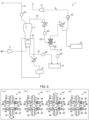
- Fig. 1 is a diagram schematically illustrating an example of how a production apparatus 1 in accordance with Embodiment 1 of the present invention is configured.
- the present specification describes the production apparatus 1 as any apparatus for producing trichlorosilane with use of metallurgical grade silicon powder.
- the production apparatus 1 is, for example, a fluidized-bed reactor.
- the use of a fluidized-bed reactor makes it possible to continuously supply metallurgical grade silicon powder and hydrogen chloride gas and thereby continuously synthesize trichlorosilane.
- the reaction between metallurgical grade silicon powder and hydrogen chloride gas involves using a large amount of metallurgical grade silicon.
- any numerical range expressed as "A to B”, in this specification, means “not less than A and not more than B (between A and B inclusive)", unless otherwise specified.
- an apparatus to produce trichlorosilane by allowing metallurgical grade silicon powder and a hydrogen chloride gas to react with each other is employed as an example, as illustrated in Fig. 1 . Note, however, that an apparatus to produce trichlorosilane by using metallurgical grade silicon powder may alternatively be employed.
- metallurgical grade silicon powder refers to a solid substance that contains elemental silicon in metal form, such as metallurgical metal silicon, ferrosilicon, or polysilicon. Any of known such materials may be used without any limitation. These kinds of metallurgical grade silicon powder may contain some impurity(impurities) such as an iron compound. The constituents and amounts of such impurities are not particularly limited. Usually, the metallurgical grade silicon powder is used in the form of fine powder having an average particle diameter of about 150 to 350 ⁇ m.
- the production apparatus 1 includes compressors 2 and 11, a reaction vessel 3, coolers 4, 7, and 9, a filter 5, a container tank 6, a heat medium drum 8, a condenser 10, a distillation column 13, and non-sliding valves b1 to b4. These constituent elements of the production apparatus 1 are connected with one another with use of pipes.
- the production apparatus 1 further includes pipes through which metallurgical grade silicon powder flows, for production of trichlorosilane.
- the pipes through which metallurgical grade silicon powder flows are each a pipe for a channel through which metallurgical grade silicon powder flows in a trichlorosilane production system.
- the pipe for a channel through which metallurgical grade silicon powder flows is, for example, a pipe for an entry channel f1, an exit channel f2, a discharge channel f31, or a discharge channel f32 (each of which will be described later).
- the trichlorosilane production system refers to an entire production apparatus for producing trichlorosilane, and refers to the entire production apparatus 1, for example.
- a method for producing trichlorosilane with use of the production apparatus 1 involves use of the non-sliding valves b1 to b4 to each open and close a channel through which metallurgical grade silicon powder flows in the trichlorosilane production system.
- a channel through which metallurgical grade silicon powder flows in a trichlorosilane production system is, for example, the entry channel f1, the exit channel f2, the discharge channel f31, or the discharge channel f32 (each of which will be described later).
- the compressor 2 is provided for a pipe through which hydrogen chloride gas flows, and is configured to compress hydrogen chloride gas flowing through the pipe and supply hydrogen chloride gas to the reaction vessel 3.
- the reaction vessel 3 is configured to receive externally supplied metallurgical grade silicon powder and hydrogen chloride gas and cause metallurgical grade silicon powder and hydrogen chloride gas to react with each other for production of trichlorosilane.
- the shape of the reaction vessel 3 (in other words, the shape of the side wall of the reaction vessel 3) is not particularly limited.
- a portion, which surrounds a fluid bed (not shown), of the side wall of the reaction vessel 3 may be (i) shaped such that its cross section perpendicular to the height direction of the reaction vessel 3 is uniform in area (not shown) or may be (ii) tapered such that its cross section perpendicular to the height direction of the reaction vessel 3 increases in area in an upward direction (not shown).
- the side wall may be tapered such that the tapered portion, whose cross section perpendicular to the height direction of the reaction vessel 3 increases in area in the upward direction, occupies a range from the gas feed opening to at least 80% of the distance from the gas feed opening to the top face of the fluid bed.
- the shape of the reaction vessel 3 is preferably a tapered shape, because this makes it possible to reduce the risk of erosion and to prevent local temperature increases.
- the reaction vessel 3 receives externally supplied metallurgical grade silicon powder through a pipe for the entry channel f1 which pipe is provided with a non-sliding valve b1.
- the non-sliding valve b1 as illustrated in Fig. 2 , includes stems 31 and 32, a valve body 33, valve seats 35 and 36, and a body section 40.
- the non-sliding valve b1 is configured to open and close the entry channel f1.
- the entry channel f1 is part of the channel through which metallurgical grade silicon powder flows in the trichlorosilane production system.
- Metallurgical grade silicon powder has small particle diameters. Minimizing a sliding portion of a conventional valve will still let metallurgical grade silicon powder enter the sliding portion while the valve is sliding, causing a valve seat to be damaged by the metallurgical grade silicon powder. It is thus preferable to use a non-sliding valve b1, which has no sliding portion.
- the above arrangement can reduce damage caused to the valve seats 35 and 36 by metallurgical grade silicon powder becoming trapped when the non-sliding valve b1 is closed on the entry channel f1, which is configured to guide metallurgical grade silicon powder into the reaction vessel 3.
- This allows the non-sliding valve b1 to be replaced less frequently, thereby allowing the replacement of the non-sliding valve b1 to be less expensive.
- Reaction between metallurgical grade silicon powder and hydrogen chloride gas for production of trichlorosilane involves use of a large amount of metallurgical grade silicon.
- the entry channel f1 is provided with a valve that is opened and closed frequently.
- the non-sliding valve b1 is provided on the entry channel f1.
- the production apparatus 1 includes a heat medium pipe 15 which extends through the reaction vessel 3 and through which a heat medium flows.
- the heat medium pipe 15 connects the cooler 7 and the heat medium drum 8 with each other.
- the cooler 7 is configured to lower the temperature of a heat medium flowing through the heat medium pipe 15.
- the heat medium drum 8 is configured to pool a heat medium.
- Metallurgical grade silicon powder taken out from a lower portion of the reaction vessel 3 flows through a pipe for the exit channel f2 which pipe is provided with a non-sliding valve b2.
- the non-sliding valve b2 is configured to open and close the exit channel f2.
- the exit channel f2 is present between the reaction vessel 3 and the container tank 6, which is configured to contain metallurgical grade silicon powder taken out from a lower portion of the reaction vessel 3.
- the exit channel f2 is part of the channel through which metallurgical grade silicon powder flows in the trichlorosilane production system.
- the above arrangement can reduce damage caused to the valve seats by metallurgical grade silicon powder becoming trapped when the non-sliding valve b2 is closed on the exit channel f2, through which metallurgical grade silicon powder taken out from a lower portion of the reaction vessel 3 flows. This allows the non-sliding valve b2 to be replaced less frequently, thereby allowing the replacement of the non-sliding valve b2 to be less expensive.
- Reaction between metallurgical grade silicon powder and hydrogen chloride gas for production of trichlorosilane involves use of a large amount of metallurgical grade silicon. This means a large amount of metallurgical grade silicon powder taken out from a lower portion of the reaction vessel 3.
- the non-sliding valve b2 is provided on the exit channel f2. This allows an aspect of the present invention to particularly significantly produce an effect of reducing damage to the valve seats during reaction between metallurgical grade silicon powder and hydrogen chloride gas for production of trichlorosilane.
- the discharge channel f3 includes a discharge channel f31, a pipe for which is provided with a non-sliding valve b3.
- the non-sliding valve b3 is configured to open and close the discharge channel f31.
- the non-sliding valve b3 is present between the cooler 4 and the filter 5.
- the discharge channel f31 is present between the reaction vessel 3 and the filter 5, which is configured to remove metallurgical grade silicon powder.
- the discharge channel f31 is part of the channel through which metallurgical grade silicon powder flows in the trichlorosilane production system.
- the non-sliding valve b3 may alternatively be present between the reaction vessel 3 and the cooler 4.
- the above arrangement can reduce damage caused to the valve seats by metallurgical grade silicon powder becoming trapped when the non-sliding valve b3 is closed on the discharge channel f31, through which metallurgical grade silicon powder discharged from an upper portion of the reaction vessel 3 flows. This allows the non-sliding valve b3 to be replaced less frequently, thereby allowing the replacement of the non-sliding valve b3 to be less expensive.
- the discharge channel f3 includes a discharge channel f32, through which metallurgical grade silicon powder removed with use of the filter 5 flows.
- a pipe for the discharge channel f32 is provided with a non-sliding valve b4.
- the non-sliding valve b4 is configured to open and close the discharge channel f32.
- the discharge channel f32 is present between the filter 5 and the container tank 6.
- the discharge channel f32 is part of the channel through which metallurgical grade silicon powder flows in the trichlorosilane production system.
- the above arrangement can reduce damage caused to the valve seats by metallurgical grade silicon powder becoming trapped when the non-sliding valve b4 is closed on the discharge channel f32, through which metallurgical grade silicon powder flows. This allows the non-sliding valve b4 to be replaced less frequently, thereby allowing the replacement of the non-sliding valve b4 to be less expensive.
- the discharge channel f31 lets hydrogen gas and trichlorosilane, tetrachlorosilane, and the like produced in the reaction vessel 3 flow therethrough.
- the pipe for the discharge channel f31 is provided with the cooler 4.
- the cooler 4 is configured to cool metallurgical grade silicon powder, hydrogen gas, trichlorosilane, tetrachlorosilane, and the like each flowing through the discharge channel f31.
- the filter 5 is configured to filter out metallurgical grade silicon powder from among metallurgical grade silicon powder, hydrogen gas, trichlorosilane, tetrachlorosilane, and the like each cooled by the cooler 4.
- the filter 5 is configured to discharge metallurgical grade silicon powder that the filter 5 has removed to the container tank 6 and supply hydrogen gas, trichlorosilane, tetrachlorosilane, and the like to the cooler 9.
- the cooler 9 is configured to cool hydrogen gas, trichlorosilane, tetrachlorosilane, and the like with use of cooling water and supply the hydrogen gas, trichlorosilane, tetrachlorosilane, and the like that the cooler 9 has cooled to the condenser 10.
- the condenser 10 is configured to cause gas-liquid separation of hydrogen gas, trichlorosilane, tetrachlorosilane, and the like to supply hydrogen gas to the compressor 11 and trichlorosilane, tetrachlorosilane, and the like to the distillation column 13.
- the distillation column 13 is configured to collect trichlorosilane and tetrachlorosilane by distillation.
- FIG. 2 are each a diagram illustrating how the non-sliding valve b1 included in the production apparatus 1 operates in a case where the non-sliding valve b1 becomes closed.
- FIG. 3 are each a diagram illustrating how the non-sliding valve b1 included in the production apparatus 1 operates in a case where the non-sliding valve b1 becomes open.
- a pipe 34 is a pipe for the entry channel f1, on which the non-sliding valve b1 is provided.
- (a) of Fig. 2 illustrates the non-sliding valve b1 as it is fully open.
- the valve body 33 has an opening section 37.
- Metallurgical grade silicon powder flowing through the pipe 34 passes through a space defined by the opening section 37.
- Metallurgical grade silicon powder flows in a direction from an entry section 38 of the non-sliding valve b1 to an exit section 39 thereof.
- the valve body 33 has an upper end to which the stem 31 is attached and a lower end to which the stem 32 is attached.
- the body section 40 has an upper depressed portion 41 that shares a boundary with the entry section 38, at which boundary the valve seat 35 is provided.
- the body section 40 has a lower depressed portion 42 that shares a boundary with the entry section 38, at which boundary the valve seat 36 is provided.
- the valve seats 35 and 36 help keep the non-sliding valve b1 airtight.
- the valve seats 35 and 36 may each be made of, for example, carbon, Teflon (registered trademark), another resin material, or metal.
- Rotating the stem 32 clockwise as viewed from below the non-sliding valve b1 as illustrated in (a) of Fig. 2 rotates the valve body 33 in a direction that causes the valve body 33 to become closed.
- the valve body 33 when rotated, does not come into contact with the valve seats 35 and 36.
- Rotating the stem 32 clockwise by 90 degrees closes the valve body 33 as illustrated in (b) of Fig. 2 .
- the non-sliding valve b1 is, however, not fully closed. Simply rotating the stem 32 clockwise by 90 degrees does not bring the valve body 33 into contact with the valve seats 35 and 36.
- FIG. 3 illustrates the non-sliding valve b1 as it is fully closed.
- Rotating the stem 31 counterclockwise as viewed from above the non-sliding valve b1 as illustrated in (b) of Fig. 3 moves the valve body 33 in a direction that causes the valve body 33 to become apart from the valve seats 35 and 36 with the stem 31 as a fulcrum. Finishing rotating the stem 31 counterclockwise completely separates the valve body 33 from the valve seats 35 and 36 as illustrated in (c) of Fig. 3 .
- the non-sliding valve b1 includes a valve body 33 capable of being rotated without coming into contact with the valve seats 35 and 36.
- the non-sliding valve b1 is provided for the pipe 34 and is configured to open and close the channel of the pipe 34. This prevents the valve seats 35 and 36 of the non-sliding valve b1 from being damaged by metallurgical grade silicon powder, thereby preventing an internal leak.
- the non-sliding valve b1 since the non-sliding valve b1 includes a valve body 33 capable of being rotated without coming into contact with the valve seats 35 and 36, the non-sliding valve b1 has an improved durability. This facilitates continuous production of trichlorosilane.
- the non-sliding valve b1 may be structured such that the valve body 33 and the valve seats 35 and 36 metal-touch each other.
- Metal touch refers to contact between things made of metal.
- the valve body 33 and the valve seats 35 and 36 are each made of metal. Rotating the stem 31 clockwise brings the valve body 33 and the valve seats 35 and 36 into contact with each other.
- the non-sliding valve b1 is closed, the valve body 33 and the valve seats 35 and 36 metal-touch each other. This allows the non-sliding valve b1 to have a heat-resistant temperature exceeding 200°C and be used at a temperature exceeding 200°C.
- the non-sliding valves b2 to b4 and non-sliding valves b5 to b8 described later each have a structure similar to that of the non-sliding valve b1.
- the respective structures of the non-sliding valves b1 to b8 are not necessarily as described above.
- the non-sliding valves b1 to b8 may each be structured in any manner as long as the valve body and valve seats do not slide on each other.
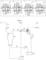
- Fig. 4 is a diagram schematically illustrating an example of how a production apparatus 1 in accordance with Embodiment 2 of the present invention is configured.
- any member of the present embodiment that is identical in function to a member described for the above embodiment is assigned the same reference sign, and is not described again here.
- the production apparatus 1 includes, in addition to the members illustrated in Fig. 1 , a heat exchanger 21, a heater 22, a second reaction vessel 23, a second filter 24, a second container tank 25, and non-sliding valves b5 to b8, each illustrated in Fig. 4 . These constituent elements of the production apparatus 1 are connected with one another with use of pipes.
- the channel through which metallurgical grade silicon powder flows in a trichlorosilane production system includes a second entry channel f5, a second discharge channel f61, a second discharge channel f62, and a second exit channel f8.
- the heat exchanger 21 receives hydrogen gas and tetrachlorosilane.
- the tetrachlorosilane may, for example, have been produced by a side reaction in the above-described reaction vessel 3.
- the heat exchanger 21 is configured to cause metallurgical grade silicon powder, hydrogen gas, and trichlorosilane supplied from the second reaction vessel 23 to exchange heat with hydrogen gas and tetrachlorosilane.
- the heat exchanger 21 supplies hydrogen gas and tetrachlorosilane to the heater 22.
- the heater 22 is configured to heat tetrachlorosilane and hydrogen gas and supply tetrachlorosilane and hydrogen gas to the second reaction vessel 23.
- the second reaction vessel 23 is configured to contain tetrachlorosilane, hydrogen gas, and externally supplied metallurgical grade silicon powder and cause tetrachlorosilane, hydrogen gas, and metallurgical grade silicon powder to react with one another to produce trichlorosilane.
- the second reaction vessel 23 is configured to supply metallurgical grade silicon powder, hydrogen gas, trichlorosilane, and unreacted tetrachlorosilane to the second filter 24 via the heat exchanger 21.
- the second filter 24 is configured to remove metallurgical grade silicon powder from among metallurgical grade silicon powder, hydrogen gas, trichlorosilane, and unreacted tetrachlorosilane supplied from the second reaction vessel 23 via the heat exchanger 21.
- the second filter 24 is configured to supply, to the second container tank 25, metallurgical grade silicon powder that the second filter 24 has removed.
- the second reaction vessel 23 receives externally supplied metallurgical grade silicon powder through a pipe for the second entry channel f5 which pipe is provided with a non-sliding valve b5.
- the non-sliding valve b5 is configured to open and close the second entry channel f5.
- the second entry channel f5 is part of the channel through which metallurgical grade silicon powder flows in the trichlorosilane production system.
- the above arrangement can reduce damage caused to the valve seats by metallurgical grade silicon powder becoming trapped when the non-sliding valve b5 is closed on the second entry channel f5, which is configured to guide metallurgical grade silicon powder into the second reaction vessel 23. This allows the non-sliding valve b5 to be replaced less frequently, thereby allowing the replacement of the non-sliding valve b5 to be less expensive.
- the second discharge channel f6 includes a second discharge channel f61, a pipe for which is provided with a non-sliding valve b6.
- the non-sliding valve b6 is configured to open and close the second discharge channel f61.
- the non-sliding valve b6 is present between the heat exchanger 21 and the second filter 24.
- the second discharge channel f61 is present between the second reaction vessel 23 and the second filter 24, which is configured to remove metallurgical grade silicon powder.
- the second discharge channel f61 is part of the channel through which metallurgical grade silicon powder flows in the trichlorosilane production system.
- the non-sliding valve b6 may alternatively be present between the second reaction vessel 23 and the heat exchanger 21.
- the above arrangement can reduce damage caused to the valve seats by metallurgical grade silicon powder becoming trapped when the non-sliding valve b6 is closed on the second discharge channel f61, through which metallurgical grade silicon powder discharged from the second reaction vessel 23 flows. This allows the non-sliding valve b6 to be replaced less frequently, thereby allowing the replacement of the non-sliding valve b6 to be less expensive.
- the second discharge channel f6 includes a second discharge channel f62, through which metallurgical grade silicon powder removed with use of the second filter 24 flows.
- a pipe for the second discharge channel f62 is provided with a non-sliding valve b7.
- the non-sliding valve b7 is configured to open and close the second discharge channel f62.
- the second discharge channel f62 is present between the second filter 24 and the second container tank 25.
- the second discharge channel f62 is part of the channel through which metallurgical grade silicon powder flows in the trichlorosilane production system.
- the above arrangement can reduce damage caused to the valve seats by metallurgical grade silicon powder becoming trapped when the non-sliding valve b7 is closed on the second discharge channel f62, through which metallurgical grade silicon powder flows. This allows the non-sliding valve b7 to be replaced less frequently, thereby allowing the replacement of the non-sliding valve b7 to be less expensive.
- Metallurgical grade silicon powder taken out from a lower portion of the second reaction vessel 23 flows through a pipe for the second exit channel f8 which pipe is provided with a non-sliding valve b8.
- the non-sliding valve b8 is configured to open and close the second exit channel f8.
- the second exit channel f8 is present between the second reaction vessel 23 and the second container tank 25, which is configured to contain metallurgical grade silicon powder taken out from a lower portion of the second reaction vessel 23.
- the second exit channel f8 is part of the channel through which metallurgical grade silicon powder flows in the trichlorosilane production system.
- the above arrangement can reduce damage caused to the valve seats by metallurgical grade silicon powder becoming trapped when the non-sliding valve b8 is closed on the second exit channel f8, through which metallurgical grade silicon powder taken out from a lower portion of the second reaction vessel 23 flows. This allows the non-sliding valve b8 to be replaced less frequently, thereby allowing the replacement of the non-sliding valve b8 to be less expensive.
- the present invention is not limited to the embodiments, but can be altered by a skilled person in the art within the scope of the claims.
- the present invention also encompasses, in its technical scope, any embodiment derived by combining technical means disclosed in differing embodiments.
- a production method as an aspect of the present invention is a method for producing trichlorosilane includes opening and closing a channel with use of a non-sliding valve, the channel being a channel through which metallurgical grade silicon powder flows in a system for producing the trichlorosilane, the non-sliding valve including a valve body capable of being rotated without coming into contact with a valve seat.
- the non-sliding valve includes a valve body capable of being rotated without coming into contact with a valve seat. This prevents the valve seats of the non-sliding valve from being damaged by metallurgical grade silicon powder, thereby preventing an internal leak. Further, since the non-sliding valve includes a valve body capable of being rotated without coming into contact with the valve seats, the non-sliding valve has an improved durability. This facilitates continuous production of trichlorosilane.
- a production method as an aspect of the present invention may preferably further include causing the metallurgical grade silicon powder and hydrogen chloride gas to react with each other for production of the trichlorosilane.
- the above arrangement can, in a case where metallurgical grade silicon powder and hydrogen chloride gas are caused to react with each other for production of trichlorosilane, prevent the valve seats of the non-sliding valve from being damaged by metallurgical grade silicon powder, thereby preventing an internal leak. Further, since the non-sliding valve includes a valve body capable of being rotated without coming into contact with the valve seats, the non-sliding valve has an improved durability. This facilitates continuous production of trichlorosilane.
- a production method as an aspect of the present invention may preferably be arranged such that the channel includes an entry channel configured to guide the metallurgical grade silicon powder into a reaction vessel for causing the metallurgical grade silicon powder and the hydrogen chloride gas to react with each other for production of the trichlorosilane, and the entry channel is opened and closed with use of the non-sliding valve.
- the above arrangement involves use of a non-sliding valve to open and close an entry channel, which is configured to guide metallurgical grade silicon powder into a reaction vessel.
- Metallurgical grade silicon powder has small particle diameters. Minimizing a sliding portion of a conventional valve will still let metallurgical grade silicon powder enter the sliding portion while the valve is sliding, causing a valve seat to be damaged by the metallurgical grade silicon powder. It is thus preferable to use a non-sliding valve, which has no sliding portion.
- the valve seat of the non-sliding valve is not easily damaged by metallurgical grade silicon powder becoming trapped. This allows the non-sliding valve to be replaced less frequently, thereby allowing the replacement of the non-sliding valve to be less expensive.
- a production method as an aspect of the present invention may preferably be arranged such that the channel includes an exit channel through which the metallurgical grade silicon powder taken out from a lower portion of a reaction vessel flows, the reaction vessel being a reaction vessel for causing the metallurgical grade silicon powder and the hydrogen chloride gas to react with each other for production of the trichlorosilane, the exit channel is present between the reaction vessel and a container tank configured to contain the metallurgical grade silicon powder taken out from the lower portion of the reaction vessel, and the exit channel is opened and closed with use of the non-sliding valve.
- the above arrangement involves use of a non-sliding valve to open and close an exit channel through which metallurgical grade silicon powder taken out from a lower portion of a reaction vessel flows.
- the valve seat of the non-sliding valve is not easily damaged by metallurgical grade silicon powder becoming trapped. This allows the non-sliding valve to be replaced less frequently, thereby allowing the replacement of the non-sliding valve to be less expensive.
- a production method as an aspect of the present invention may preferably be arranged such that the channel includes a discharge channel through which the metallurgical grade silicon powder discharged from an upper portion of a reaction vessel flows, the reaction vessel being a reaction vessel for causing the metallurgical grade silicon powder and the hydrogen chloride gas to react with each other for production of the trichlorosilane, the discharge channel is present between the reaction vessel and a filter configured to remove the metallurgical grade silicon powder, and the discharge channel is opened and closed with use of the non-sliding valve.
- the above arrangement involves use of a non-sliding valve to open and close a discharge channel through which metallurgical grade silicon powder discharged from an upper portion of a reaction vessel flows.
- a non-sliding valve to open and close a discharge channel through which metallurgical grade silicon powder discharged from an upper portion of a reaction vessel flows.
- a production method as an aspect of the present invention may preferably be arranged such that the channel includes a discharge channel through which the metallurgical grade silicon powder discharged from an upper portion of a reaction vessel flows, the reaction vessel being a reaction vessel for causing the metallurgical grade silicon powder and the hydrogen chloride gas to react with each other for production of the trichlorosilane, the discharge channel is present between (i) a filter configured to remove the metallurgical grade silicon powder and (ii) a container tank configured to contain the metallurgical grade silicon powder having been removed with use of the filter, and the discharge channel is opened and closed with use of the non-sliding valve.
- the above arrangement involves use of a non-sliding valve to open and close a discharge channel present between (i) a filter configured to remove metallurgical grade silicon powder and (ii) a container tank configured to contain metallurgical grade silicon powder having been removed with use of the filter.
- a non-sliding valve to open and close a discharge channel present between (i) a filter configured to remove metallurgical grade silicon powder and (ii) a container tank configured to contain metallurgical grade silicon powder having been removed with use of the filter.
- a production apparatus as an aspect of the present invention is an apparatus for producing trichlorosilane, the apparatus including: a pipe configured to allow metallurgical grade silicon powder to flow therethrough; and a non-sliding valve including a valve body capable of being rotated without coming into contact with a valve seat, the non-sliding valve being (i) provided for the pipe in a system for producing the trichlorosilane and (ii) configured to open and close a channel of the pipe.
- the non-sliding valve includes a valve body capable of being rotated without coming into contact with a valve seat. This prevents the valve seats of the non-sliding valve from being damaged by metallurgical grade silicon powder, thereby preventing an internal leak. Further, since the non-sliding valve includes a valve body capable of being rotated without coming into contact with the valve seats, the non-sliding valve has an improved durability. This facilitates continuous production of trichlorosilane.
- a production apparatus as an aspect of the present invention may preferably be arranged such that the non-sliding valve is structured such that the valve body and the valve seat metal-touch each other.
- the non-sliding valve is structured such that the valve body and the valve seat metal-touch each other. This allows the non-sliding valve to have a heat-resistant temperature exceeding 200°C and be used at a temperature exceeding 200°C.
- the present invention is applicable to production of trichlorosilane.
Landscapes
- Chemical & Material Sciences (AREA)
- Organic Chemistry (AREA)
- Engineering & Computer Science (AREA)
- General Engineering & Computer Science (AREA)
- Inorganic Chemistry (AREA)
- Mechanical Engineering (AREA)
- Silicon Compounds (AREA)
- Taps Or Cocks (AREA)
Claims (8)
- Verfahren zur Herstellung von Trichlorsilan, wobei das Verfahren Folgendes aufweist:
Öffnen und Schließen eines Kanals unter Verwendung eines nicht gleitenden Ventils, wobei der Kanal ein Kanal ist, durch den Silicium-Pulver metallurgischer Qualität fließt in einem System zur Herstellung des Trichlorsilans, wobei das nicht gleitende Ventil einen Ventilkörper aufweist, der in der Lage ist, gedreht zu werden, ohne mit einem Ventilsitz in Kontakt zu gelangen. - Verfahren nach Anspruch 1, ferner aufweisend:
Bewirken, dass das Silicium-Pulver metallurgischer Qualität und Chlorwasserstoffgas zur Herstellung des Trichlorsilans miteinander reagieren. - Verfahren nach Anspruch 2, wobeider Kanal einen Eintrittskanal aufweist, der dafür ausgelegt ist, um das Silicium-Pulver metallurgischer Qualität in ein Reaktionsgefäß zu führen, um zu bewirken, dass das Silicium-Pulver metallurgischer Qualität und das Chlorwasserstoffgas zur Herstellung des Trichlorsilans miteinander reagieren, undder Eintrittskanal unter Verwendung des nicht gleitenden Ventils geöffnet und geschlossen wird.
- Verfahren nach Anspruch 2 oder 3, wobeider Kanal einen Austrittskanal aufweist, durch den das Silicium-Pulver metallurgischer Qualität, das aus einem unteren Abschnitt eines Reaktionsgefäßes entnommen wird, strömt, wobei das Reaktionsgefäß ein Reaktionsgefäß ist, um zu bewirken, dass das Silicium-Pulver metallurgischer Qualität und das Chlorwasserstoffgas zur Herstellung des Trichlorsilans miteinander reagieren,der Austrittskanal zwischen dem Reaktionsgefäß und einem Behältertank vorhanden ist, der dafür ausgelegt ist, um das Silicium-Pulver metallurgischer Qualität, das aus dem unteren Abschnitt des Reaktionsgefäßes entnommen wird, zu enthalten, undder Austrittskanal unter Verwendung des nicht gleitenden Ventils geöffnet und geschlossen wird.
- Verfahren nach einem der Ansprüche 2 bis 4, wobeider Kanal einen Abgabekanal aufweist, durch den das Silicium-Pulver metallurgischer Qualität, das aus einem oberen Abschnitt eines Reaktionsgefäßes abgegeben wird, strömt, wobei das Reaktionsgefäß ein Reaktionsgefäß ist, um zu bewirken, dass das Silicium-Pulver metallurgischer Qualität und das Chlorwasserstoffgas zur Herstellung des Trichlorsilans miteinander reagieren,der Abgabekanal zwischen dem Reaktionsgefäß und einem Filter vorhanden ist, der dafür ausgelegt ist, um das Silicium-Pulver metallurgischer Qualität zu entfernen, und der Abgabekanal unter Verwendung des nicht gleitenden Ventils geöffnet und geschlossen wird.
- Verfahren nach einem der Ansprüche 2 bis 4, wobeider Kanal einen Abgabekanal aufweist, durch den das Silicium-Pulver metallurgischer Qualität, das aus einem oberen Abschnitt eines Reaktionsgefäßes abgegeben wird, strömt, wobei das Reaktionsgefäß ein Reaktionsgefäß ist, um zu bewirken, dass das Silicium-Pulver metallurgischer Qualität und das Chlorwasserstoffgas zur Herstellung des Trichlorsilans miteinander reagieren,der Abgabekanal vorhanden ist zwischen (i) einem Filter, der dafür ausgelegt ist, um das Silicium-Pulver metallurgischer Qualität zu entfernen, und (ii) einem Behältertank, der dafür ausgelegt ist, um das Silicium-Pulver metallurgischer Qualität, das unter Verwendung des Filters entfernt wurde, zu enthalten, undder Abgabekanal unter Verwendung des nicht gleitenden Ventils geöffnet und geschlossen wird.
- Vorrichtung zur Herstellung von Trichlorsilan, wobei die Vorrichtung Folgendes aufweist:einen Kanal, der dafür ausgelegt ist, um zu gestatten, dass Silicium-Pulver metallurgischer Qualität hindurchströmt; undein nicht gleitendes Ventil, das einen Ventilkörper aufweist, der in der Lage ist, gedreht zu werden, ohne mit einem Ventilsitz in Kontakt zu gelangen,wobei das nicht gleitende Ventil (i) für den Kanal in einem System zur Herstellung des Trichlorsilans bereitgestellt ist, und (ii) dafür ausgelegt ist, um den Kanal zu öffnen und zu schließen.
- Vorrichtung nach Anspruch 7, wobei
das nicht gleitende Ventil derart strukturiert ist, dass der Ventilkörper und der Ventilsitz einander Metall-berühren.
Applications Claiming Priority (2)
| Application Number | Priority Date | Filing Date | Title |
|---|---|---|---|
| JP2017223149 | 2017-11-20 | ||
| PCT/JP2018/042556 WO2019098344A1 (ja) | 2017-11-20 | 2018-11-16 | トリクロロシランの製造方法及びトリクロロシランの製造装置 |
Publications (3)
| Publication Number | Publication Date |
|---|---|
| EP3715325A1 EP3715325A1 (de) | 2020-09-30 |
| EP3715325A4 EP3715325A4 (de) | 2021-06-02 |
| EP3715325B1 true EP3715325B1 (de) | 2023-05-31 |
Family
ID=66539055
Family Applications (1)
| Application Number | Title | Priority Date | Filing Date |
|---|---|---|---|
| EP18878111.6A Active EP3715325B1 (de) | 2017-11-20 | 2018-11-16 | Verfahren zur herstellung von trichlorsilan und vorrichtung zur herstellung von trichlorsilan |
Country Status (7)
| Country | Link |
|---|---|
| US (1) | US20200339427A1 (de) |
| EP (1) | EP3715325B1 (de) |
| JP (1) | JP6564550B1 (de) |
| KR (1) | KR102599877B1 (de) |
| CN (1) | CN111372892B (de) |
| TW (1) | TWI761631B (de) |
| WO (1) | WO2019098344A1 (de) |
Families Citing this family (2)
| Publication number | Priority date | Publication date | Assignee | Title |
|---|---|---|---|---|
| WO2021100415A1 (ja) * | 2019-11-21 | 2021-05-27 | 株式会社トクヤマ | 多結晶シリコンの製造装置および多結晶シリコンの製造方法 |
| JP7605752B2 (ja) * | 2019-11-22 | 2024-12-24 | 株式会社トクヤマ | トリクロロシランの製造方法及びトリクロロシランの製造装置 |
Family Cites Families (16)
| Publication number | Priority date | Publication date | Assignee | Title |
|---|---|---|---|---|
| JP2516307Y2 (ja) * | 1988-03-09 | 1996-11-06 | 株式会社 巴技術研究所 | バタフライ弁 |
| JPH07190211A (ja) * | 1993-12-27 | 1995-07-28 | Sekisui Plastics Co Ltd | 粒子用制御弁 |
| JP2976172B2 (ja) * | 1994-08-11 | 1999-11-10 | 株式会社トクヤマ | 気体遮断弁 |
| US20100146886A1 (en) | 2007-02-22 | 2010-06-17 | Bizhong Zhu | Composite Article Having Excellent Fire Resistance |
| EP2055375B1 (de) * | 2007-10-25 | 2012-05-02 | Mitsubishi Materials Corporation | HCl-Ejektionsdüse, Reaktor und Verfahren zur Herstellung von Trichlorosilan |
| JP5343437B2 (ja) * | 2007-10-25 | 2013-11-13 | 三菱マテリアル株式会社 | 塩化水素ガス噴出用部材及びトリクロロシラン製造用反応装置並びにトリクロロシラン製造方法 |
| US20100264362A1 (en) * | 2008-07-01 | 2010-10-21 | Yongchae Chee | Method of producing trichlorosilane (TCS) rich Chlorosilane product stably from a fluidized gas phase reactor (FBR) and the structure of the reactor |
| KR101687833B1 (ko) * | 2009-01-20 | 2016-12-19 | 미쓰비시 마테리알 가부시키가이샤 | 트리클로로실란 제조 장치 및 트리클로로실란 제조 방법 |
| WO2011009390A1 (zh) * | 2009-07-19 | 2011-01-27 | Chu Xi | 硅气转化的反应器和方法 |
| EP2720787A1 (de) * | 2011-06-16 | 2014-04-23 | Hemlock Semiconductor Corporation | Ventil zur feststoffverarbeitung |
| CN202297152U (zh) * | 2011-09-30 | 2012-07-04 | 河南尚宇新能源股份有限公司 | 三氯氢硅生产过程中减少硅粉消耗的装置 |
| CN202659960U (zh) * | 2012-05-10 | 2013-01-09 | 重庆海王仪器仪表有限公司 | 多晶硅三氯氢硅介质硬密封专用球阀 |
| CN103408022B (zh) * | 2013-07-08 | 2016-03-30 | 昆明冶研新材料股份有限公司 | 硅粉传输设备以及具有其的合成三氯氢硅的系统 |
| CN106276919B (zh) * | 2015-06-26 | 2019-10-15 | 新特能源股份有限公司 | 用于多晶硅生产中的除尘系统和除尘方法 |
| CN204961893U (zh) * | 2015-09-15 | 2016-01-13 | 重庆川仪特种阀门修造有限公司 | 硅粉尾气专用球阀 |
| CN204942601U (zh) * | 2015-09-18 | 2016-01-06 | 苏州道森阀门有限公司 | 硅粉输送管道用球阀 |
-
2018
- 2018-11-16 CN CN201880074820.1A patent/CN111372892B/zh active Active
- 2018-11-16 US US16/765,379 patent/US20200339427A1/en not_active Abandoned
- 2018-11-16 JP JP2019519363A patent/JP6564550B1/ja active Active
- 2018-11-16 TW TW107140849A patent/TWI761631B/zh active
- 2018-11-16 WO PCT/JP2018/042556 patent/WO2019098344A1/ja not_active Ceased
- 2018-11-16 EP EP18878111.6A patent/EP3715325B1/de active Active
- 2018-11-16 KR KR1020207014301A patent/KR102599877B1/ko active Active
Also Published As
| Publication number | Publication date |
|---|---|
| WO2019098344A1 (ja) | 2019-05-23 |
| US20200339427A1 (en) | 2020-10-29 |
| TWI761631B (zh) | 2022-04-21 |
| CN111372892B (zh) | 2023-05-23 |
| JPWO2019098344A1 (ja) | 2019-11-21 |
| KR102599877B1 (ko) | 2023-11-09 |
| EP3715325A1 (de) | 2020-09-30 |
| TW201922616A (zh) | 2019-06-16 |
| KR20200088332A (ko) | 2020-07-22 |
| JP6564550B1 (ja) | 2019-08-21 |
| CN111372892A (zh) | 2020-07-03 |
| EP3715325A4 (de) | 2021-06-02 |
Similar Documents
| Publication | Publication Date | Title |
|---|---|---|
| TWI507359B (zh) | 製備三氯矽烷之方法及設備 | |
| CN103648631B (zh) | 固体加工阀 | |
| JP5316290B2 (ja) | トリクロロシラン製造装置及び製造方法 | |
| EP3715325A1 (de) | Verfahren zur herstellung von trichlorsilan und vorrichtung zur herstellung von trichlorsilan | |
| JP5387267B2 (ja) | クロロシラン精製装置及び精製方法 | |
| US20040042950A1 (en) | Method for producing high-purity, granular silicon | |
| EP1697040B1 (de) | Vorrichtung und verfahren zur abscheidung ultrafeiner teilchen aus der gasphase | |
| CN111072033B (zh) | 氯硅烷残液的预处理系统和方法 | |
| US10322938B2 (en) | Poly-silicon manufacturing apparatus and method using high-efficiency hybrid horizontal reactor | |
| US20200277197A1 (en) | Trichlorosilane manufacturing apparatus, and method for manufacturing trichlorosilane | |
| JP7605752B2 (ja) | トリクロロシランの製造方法及びトリクロロシランの製造装置 | |
| EP3640204B1 (de) | Verfahren zur herstellung von polysilizium | |
| US10196273B2 (en) | Device for manufacturing polysilicon using horizontal reactor and method for manufacturing same | |
| US20200306714A1 (en) | Reactor and production method of trichlorosilane | |
| CA2576665C (en) | Silicon manufacturing apparatus | |
| EP3715324A1 (de) | Herstellungsverfahren für trichlorsilan und rohr | |
| RU2729691C2 (ru) | Способ алюмотермического получения металлических порошков и устройство для его осуществления | |
| JP5482265B2 (ja) | トリクロロシラン製造装置 | |
| JPS63123435A (ja) | 金属化合物の微粉末の製造方法及び装置 |
Legal Events
| Date | Code | Title | Description |
|---|---|---|---|
| STAA | Information on the status of an ep patent application or granted ep patent |
Free format text: STATUS: THE INTERNATIONAL PUBLICATION HAS BEEN MADE |
|
| PUAI | Public reference made under article 153(3) epc to a published international application that has entered the european phase |
Free format text: ORIGINAL CODE: 0009012 |
|
| STAA | Information on the status of an ep patent application or granted ep patent |
Free format text: STATUS: REQUEST FOR EXAMINATION WAS MADE |
|
| 17P | Request for examination filed |
Effective date: 20200527 |
|
| AK | Designated contracting states |
Kind code of ref document: A1 Designated state(s): AL AT BE BG CH CY CZ DE DK EE ES FI FR GB GR HR HU IE IS IT LI LT LU LV MC MK MT NL NO PL PT RO RS SE SI SK SM TR |
|
| AX | Request for extension of the european patent |
Extension state: BA ME |
|
| DAV | Request for validation of the european patent (deleted) | ||
| DAX | Request for extension of the european patent (deleted) | ||
| A4 | Supplementary search report drawn up and despatched |
Effective date: 20210503 |
|
| RIC1 | Information provided on ipc code assigned before grant |
Ipc: C01B 33/107 20060101AFI20210426BHEP Ipc: F16K 1/24 20060101ALI20210426BHEP Ipc: F16K 31/44 20060101ALI20210426BHEP Ipc: F16K 5/06 20060101ALI20210426BHEP Ipc: F16K 5/20 20060101ALI20210426BHEP |
|
| GRAP | Despatch of communication of intention to grant a patent |
Free format text: ORIGINAL CODE: EPIDOSNIGR1 |
|
| STAA | Information on the status of an ep patent application or granted ep patent |
Free format text: STATUS: GRANT OF PATENT IS INTENDED |
|
| INTG | Intention to grant announced |
Effective date: 20230203 |
|
| GRAS | Grant fee paid |
Free format text: ORIGINAL CODE: EPIDOSNIGR3 |
|
| GRAA | (expected) grant |
Free format text: ORIGINAL CODE: 0009210 |
|
| STAA | Information on the status of an ep patent application or granted ep patent |
Free format text: STATUS: THE PATENT HAS BEEN GRANTED |
|
| AK | Designated contracting states |
Kind code of ref document: B1 Designated state(s): AL AT BE BG CH CY CZ DE DK EE ES FI FR GB GR HR HU IE IS IT LI LT LU LV MC MK MT NL NO PL PT RO RS SE SI SK SM TR |
|
| REG | Reference to a national code |
Ref country code: GB Ref legal event code: FG4D Ref country code: CH Ref legal event code: EP |
|
| REG | Reference to a national code |
Ref country code: DE Ref legal event code: R096 Ref document number: 602018050580 Country of ref document: DE |
|
| REG | Reference to a national code |
Ref country code: AT Ref legal event code: REF Ref document number: 1570851 Country of ref document: AT Kind code of ref document: T Effective date: 20230615 |
|
| REG | Reference to a national code |
Ref country code: IE Ref legal event code: FG4D |
|
| REG | Reference to a national code |
Ref country code: LT Ref legal event code: MG9D |
|
| REG | Reference to a national code |
Ref country code: NL Ref legal event code: MP Effective date: 20230531 |
|
| REG | Reference to a national code |
Ref country code: AT Ref legal event code: MK05 Ref document number: 1570851 Country of ref document: AT Kind code of ref document: T Effective date: 20230531 |
|
| PG25 | Lapsed in a contracting state [announced via postgrant information from national office to epo] |
Ref country code: SE Free format text: LAPSE BECAUSE OF FAILURE TO SUBMIT A TRANSLATION OF THE DESCRIPTION OR TO PAY THE FEE WITHIN THE PRESCRIBED TIME-LIMIT Effective date: 20230531 Ref country code: NO Free format text: LAPSE BECAUSE OF FAILURE TO SUBMIT A TRANSLATION OF THE DESCRIPTION OR TO PAY THE FEE WITHIN THE PRESCRIBED TIME-LIMIT Effective date: 20230831 Ref country code: ES Free format text: LAPSE BECAUSE OF FAILURE TO SUBMIT A TRANSLATION OF THE DESCRIPTION OR TO PAY THE FEE WITHIN THE PRESCRIBED TIME-LIMIT Effective date: 20230531 Ref country code: AT Free format text: LAPSE BECAUSE OF FAILURE TO SUBMIT A TRANSLATION OF THE DESCRIPTION OR TO PAY THE FEE WITHIN THE PRESCRIBED TIME-LIMIT Effective date: 20230531 |
|
| PG25 | Lapsed in a contracting state [announced via postgrant information from national office to epo] |
Ref country code: RS Free format text: LAPSE BECAUSE OF FAILURE TO SUBMIT A TRANSLATION OF THE DESCRIPTION OR TO PAY THE FEE WITHIN THE PRESCRIBED TIME-LIMIT Effective date: 20230531 Ref country code: PL Free format text: LAPSE BECAUSE OF FAILURE TO SUBMIT A TRANSLATION OF THE DESCRIPTION OR TO PAY THE FEE WITHIN THE PRESCRIBED TIME-LIMIT Effective date: 20230531 Ref country code: NL Free format text: LAPSE BECAUSE OF FAILURE TO SUBMIT A TRANSLATION OF THE DESCRIPTION OR TO PAY THE FEE WITHIN THE PRESCRIBED TIME-LIMIT Effective date: 20230531 Ref country code: LV Free format text: LAPSE BECAUSE OF FAILURE TO SUBMIT A TRANSLATION OF THE DESCRIPTION OR TO PAY THE FEE WITHIN THE PRESCRIBED TIME-LIMIT Effective date: 20230531 Ref country code: LT Free format text: LAPSE BECAUSE OF FAILURE TO SUBMIT A TRANSLATION OF THE DESCRIPTION OR TO PAY THE FEE WITHIN THE PRESCRIBED TIME-LIMIT Effective date: 20230531 Ref country code: IS Free format text: LAPSE BECAUSE OF FAILURE TO SUBMIT A TRANSLATION OF THE DESCRIPTION OR TO PAY THE FEE WITHIN THE PRESCRIBED TIME-LIMIT Effective date: 20230930 Ref country code: HR Free format text: LAPSE BECAUSE OF FAILURE TO SUBMIT A TRANSLATION OF THE DESCRIPTION OR TO PAY THE FEE WITHIN THE PRESCRIBED TIME-LIMIT Effective date: 20230531 Ref country code: GR Free format text: LAPSE BECAUSE OF FAILURE TO SUBMIT A TRANSLATION OF THE DESCRIPTION OR TO PAY THE FEE WITHIN THE PRESCRIBED TIME-LIMIT Effective date: 20230901 |
|
| PG25 | Lapsed in a contracting state [announced via postgrant information from national office to epo] |
Ref country code: FI Free format text: LAPSE BECAUSE OF FAILURE TO SUBMIT A TRANSLATION OF THE DESCRIPTION OR TO PAY THE FEE WITHIN THE PRESCRIBED TIME-LIMIT Effective date: 20230531 |
|
| PG25 | Lapsed in a contracting state [announced via postgrant information from national office to epo] |
Ref country code: SK Free format text: LAPSE BECAUSE OF FAILURE TO SUBMIT A TRANSLATION OF THE DESCRIPTION OR TO PAY THE FEE WITHIN THE PRESCRIBED TIME-LIMIT Effective date: 20230531 |
|
| PG25 | Lapsed in a contracting state [announced via postgrant information from national office to epo] |
Ref country code: SM Free format text: LAPSE BECAUSE OF FAILURE TO SUBMIT A TRANSLATION OF THE DESCRIPTION OR TO PAY THE FEE WITHIN THE PRESCRIBED TIME-LIMIT Effective date: 20230531 Ref country code: SK Free format text: LAPSE BECAUSE OF FAILURE TO SUBMIT A TRANSLATION OF THE DESCRIPTION OR TO PAY THE FEE WITHIN THE PRESCRIBED TIME-LIMIT Effective date: 20230531 Ref country code: RO Free format text: LAPSE BECAUSE OF FAILURE TO SUBMIT A TRANSLATION OF THE DESCRIPTION OR TO PAY THE FEE WITHIN THE PRESCRIBED TIME-LIMIT Effective date: 20230531 Ref country code: PT Free format text: LAPSE BECAUSE OF FAILURE TO SUBMIT A TRANSLATION OF THE DESCRIPTION OR TO PAY THE FEE WITHIN THE PRESCRIBED TIME-LIMIT Effective date: 20231002 Ref country code: EE Free format text: LAPSE BECAUSE OF FAILURE TO SUBMIT A TRANSLATION OF THE DESCRIPTION OR TO PAY THE FEE WITHIN THE PRESCRIBED TIME-LIMIT Effective date: 20230531 Ref country code: DK Free format text: LAPSE BECAUSE OF FAILURE TO SUBMIT A TRANSLATION OF THE DESCRIPTION OR TO PAY THE FEE WITHIN THE PRESCRIBED TIME-LIMIT Effective date: 20230531 Ref country code: CZ Free format text: LAPSE BECAUSE OF FAILURE TO SUBMIT A TRANSLATION OF THE DESCRIPTION OR TO PAY THE FEE WITHIN THE PRESCRIBED TIME-LIMIT Effective date: 20230531 |
|
| REG | Reference to a national code |
Ref country code: DE Ref legal event code: R097 Ref document number: 602018050580 Country of ref document: DE |
|
| PLBE | No opposition filed within time limit |
Free format text: ORIGINAL CODE: 0009261 |
|
| STAA | Information on the status of an ep patent application or granted ep patent |
Free format text: STATUS: NO OPPOSITION FILED WITHIN TIME LIMIT |
|
| PG25 | Lapsed in a contracting state [announced via postgrant information from national office to epo] |
Ref country code: SI Free format text: LAPSE BECAUSE OF FAILURE TO SUBMIT A TRANSLATION OF THE DESCRIPTION OR TO PAY THE FEE WITHIN THE PRESCRIBED TIME-LIMIT Effective date: 20230531 |
|
| 26N | No opposition filed |
Effective date: 20240301 |
|
| PG25 | Lapsed in a contracting state [announced via postgrant information from national office to epo] |
Ref country code: SI Free format text: LAPSE BECAUSE OF FAILURE TO SUBMIT A TRANSLATION OF THE DESCRIPTION OR TO PAY THE FEE WITHIN THE PRESCRIBED TIME-LIMIT Effective date: 20230531 |
|
| REG | Reference to a national code |
Ref country code: CH Ref legal event code: PL |
|
| PG25 | Lapsed in a contracting state [announced via postgrant information from national office to epo] |
Ref country code: MC Free format text: LAPSE BECAUSE OF FAILURE TO SUBMIT A TRANSLATION OF THE DESCRIPTION OR TO PAY THE FEE WITHIN THE PRESCRIBED TIME-LIMIT Effective date: 20230531 |
|
| PG25 | Lapsed in a contracting state [announced via postgrant information from national office to epo] |
Ref country code: LU Free format text: LAPSE BECAUSE OF NON-PAYMENT OF DUE FEES Effective date: 20231116 |
|
| PG25 | Lapsed in a contracting state [announced via postgrant information from national office to epo] |
Ref country code: CH Free format text: LAPSE BECAUSE OF NON-PAYMENT OF DUE FEES Effective date: 20231130 |
|
| GBPC | Gb: european patent ceased through non-payment of renewal fee |
Effective date: 20231116 |
|
| PG25 | Lapsed in a contracting state [announced via postgrant information from national office to epo] |
Ref country code: MC Free format text: LAPSE BECAUSE OF FAILURE TO SUBMIT A TRANSLATION OF THE DESCRIPTION OR TO PAY THE FEE WITHIN THE PRESCRIBED TIME-LIMIT Effective date: 20230531 Ref country code: LU Free format text: LAPSE BECAUSE OF NON-PAYMENT OF DUE FEES Effective date: 20231116 Ref country code: CH Free format text: LAPSE BECAUSE OF NON-PAYMENT OF DUE FEES Effective date: 20231130 |
|
| REG | Reference to a national code |
Ref country code: BE Ref legal event code: MM Effective date: 20231130 |
|
| REG | Reference to a national code |
Ref country code: IE Ref legal event code: MM4A |
|
| PG25 | Lapsed in a contracting state [announced via postgrant information from national office to epo] |
Ref country code: IE Free format text: LAPSE BECAUSE OF NON-PAYMENT OF DUE FEES Effective date: 20231116 |
|
| PG25 | Lapsed in a contracting state [announced via postgrant information from national office to epo] |
Ref country code: GB Free format text: LAPSE BECAUSE OF NON-PAYMENT OF DUE FEES Effective date: 20231116 |
|
| PG25 | Lapsed in a contracting state [announced via postgrant information from national office to epo] |
Ref country code: BE Free format text: LAPSE BECAUSE OF NON-PAYMENT OF DUE FEES Effective date: 20231130 |
|
| PG25 | Lapsed in a contracting state [announced via postgrant information from national office to epo] |
Ref country code: FR Free format text: LAPSE BECAUSE OF NON-PAYMENT OF DUE FEES Effective date: 20231130 |
|
| PG25 | Lapsed in a contracting state [announced via postgrant information from national office to epo] |
Ref country code: IE Free format text: LAPSE BECAUSE OF NON-PAYMENT OF DUE FEES Effective date: 20231116 Ref country code: GB Free format text: LAPSE BECAUSE OF NON-PAYMENT OF DUE FEES Effective date: 20231116 Ref country code: FR Free format text: LAPSE BECAUSE OF NON-PAYMENT OF DUE FEES Effective date: 20231130 Ref country code: BE Free format text: LAPSE BECAUSE OF NON-PAYMENT OF DUE FEES Effective date: 20231130 |
|
| PG25 | Lapsed in a contracting state [announced via postgrant information from national office to epo] |
Ref country code: BG Free format text: LAPSE BECAUSE OF FAILURE TO SUBMIT A TRANSLATION OF THE DESCRIPTION OR TO PAY THE FEE WITHIN THE PRESCRIBED TIME-LIMIT Effective date: 20230531 |
|
| PG25 | Lapsed in a contracting state [announced via postgrant information from national office to epo] |
Ref country code: BG Free format text: LAPSE BECAUSE OF FAILURE TO SUBMIT A TRANSLATION OF THE DESCRIPTION OR TO PAY THE FEE WITHIN THE PRESCRIBED TIME-LIMIT Effective date: 20230531 |
|
| PG25 | Lapsed in a contracting state [announced via postgrant information from national office to epo] |
Ref country code: CY Free format text: LAPSE BECAUSE OF FAILURE TO SUBMIT A TRANSLATION OF THE DESCRIPTION OR TO PAY THE FEE WITHIN THE PRESCRIBED TIME-LIMIT; INVALID AB INITIO Effective date: 20181116 |
|
| PG25 | Lapsed in a contracting state [announced via postgrant information from national office to epo] |
Ref country code: HU Free format text: LAPSE BECAUSE OF FAILURE TO SUBMIT A TRANSLATION OF THE DESCRIPTION OR TO PAY THE FEE WITHIN THE PRESCRIBED TIME-LIMIT; INVALID AB INITIO Effective date: 20181116 |
|
| PG25 | Lapsed in a contracting state [announced via postgrant information from national office to epo] |
Ref country code: TR Free format text: LAPSE BECAUSE OF FAILURE TO SUBMIT A TRANSLATION OF THE DESCRIPTION OR TO PAY THE FEE WITHIN THE PRESCRIBED TIME-LIMIT Effective date: 20230531 |
|
| PGFP | Annual fee paid to national office [announced via postgrant information from national office to epo] |
Ref country code: DE Payment date: 20250930 Year of fee payment: 8 |
|
| PGFP | Annual fee paid to national office [announced via postgrant information from national office to epo] |
Ref country code: IT Payment date: 20251022 Year of fee payment: 8 |