EP3711158B1 - Schnellverschlussvorrichtung zum verbinden von fotovoltaischen solarpaneelen mit einer tragstruktur - Google Patents
Schnellverschlussvorrichtung zum verbinden von fotovoltaischen solarpaneelen mit einer tragstruktur Download PDFInfo
- Publication number
- EP3711158B1 EP3711158B1 EP18811651.1A EP18811651A EP3711158B1 EP 3711158 B1 EP3711158 B1 EP 3711158B1 EP 18811651 A EP18811651 A EP 18811651A EP 3711158 B1 EP3711158 B1 EP 3711158B1
- Authority
- EP
- European Patent Office
- Prior art keywords
- locking device
- photovoltaic solar
- support structure
- solar panel
- quick locking
- Prior art date
- Legal status (The legal status is an assumption and is not a legal conclusion. Google has not performed a legal analysis and makes no representation as to the accuracy of the status listed.)
- Active
Links
Images







Classifications
-
- H—ELECTRICITY
- H02—GENERATION; CONVERSION OR DISTRIBUTION OF ELECTRIC POWER
- H02S—GENERATION OF ELECTRIC POWER BY CONVERSION OF INFRARED RADIATION, VISIBLE LIGHT OR ULTRAVIOLET LIGHT, e.g. USING PHOTOVOLTAIC [PV] MODULES
- H02S20/00—Supporting structures for PV modules
- H02S20/20—Supporting structures directly fixed to an immovable object
-
- B—PERFORMING OPERATIONS; TRANSPORTING
- B25—HAND TOOLS; PORTABLE POWER-DRIVEN TOOLS; MANIPULATORS
- B25J—MANIPULATORS; CHAMBERS PROVIDED WITH MANIPULATION DEVICES
- B25J9/00—Program-controlled manipulators
- B25J9/16—Program controls
- B25J9/1679—Program controls characterised by the tasks executed
- B25J9/1687—Assembly, peg and hole, palletising, straight line, weaving pattern movement
-
- B—PERFORMING OPERATIONS; TRANSPORTING
- B25—HAND TOOLS; PORTABLE POWER-DRIVEN TOOLS; MANIPULATORS
- B25J—MANIPULATORS; CHAMBERS PROVIDED WITH MANIPULATION DEVICES
- B25J9/00—Program-controlled manipulators
- B25J9/16—Program controls
- B25J9/1694—Program controls characterised by use of sensors other than normal servo-feedback from position, speed or acceleration sensors, perception control, multi-sensor controlled systems, sensor fusion
- B25J9/1697—Vision controlled systems
-
- F—MECHANICAL ENGINEERING; LIGHTING; HEATING; WEAPONS; BLASTING
- F24—HEATING; RANGES; VENTILATING
- F24S—SOLAR HEAT COLLECTORS; SOLAR HEAT SYSTEMS
- F24S25/00—Arrangement of stationary mountings or supports for solar heat collector modules
- F24S25/10—Arrangement of stationary mountings or supports for solar heat collector modules extending in directions away from a supporting surface
- F24S25/12—Arrangement of stationary mountings or supports for solar heat collector modules extending in directions away from a supporting surface using posts in combination with upper profiles
-
- F—MECHANICAL ENGINEERING; LIGHTING; HEATING; WEAPONS; BLASTING
- F24—HEATING; RANGES; VENTILATING
- F24S—SOLAR HEAT COLLECTORS; SOLAR HEAT SYSTEMS
- F24S25/00—Arrangement of stationary mountings or supports for solar heat collector modules
- F24S25/20—Peripheral frames for modules
-
- F—MECHANICAL ENGINEERING; LIGHTING; HEATING; WEAPONS; BLASTING
- F24—HEATING; RANGES; VENTILATING
- F24S—SOLAR HEAT COLLECTORS; SOLAR HEAT SYSTEMS
- F24S25/00—Arrangement of stationary mountings or supports for solar heat collector modules
- F24S25/60—Fixation means, e.g. fasteners, specially adapted for supporting solar heat collector modules
- F24S25/63—Fixation means, e.g. fasteners, specially adapted for supporting solar heat collector modules for fixing modules or their peripheral frames to supporting elements
- F24S25/632—Side connectors; Base connectors
-
- H—ELECTRICITY
- H02—GENERATION; CONVERSION OR DISTRIBUTION OF ELECTRIC POWER
- H02S—GENERATION OF ELECTRIC POWER BY CONVERSION OF INFRARED RADIATION, VISIBLE LIGHT OR ULTRAVIOLET LIGHT, e.g. USING PHOTOVOLTAIC [PV] MODULES
- H02S20/00—Supporting structures for PV modules
- H02S20/20—Supporting structures directly fixed to an immovable object
- H02S20/22—Supporting structures directly fixed to an immovable object specially adapted for buildings
- H02S20/23—Supporting structures directly fixed to an immovable object specially adapted for buildings specially adapted for roof structures
-
- H—ELECTRICITY
- H02—GENERATION; CONVERSION OR DISTRIBUTION OF ELECTRIC POWER
- H02S—GENERATION OF ELECTRIC POWER BY CONVERSION OF INFRARED RADIATION, VISIBLE LIGHT OR ULTRAVIOLET LIGHT, e.g. USING PHOTOVOLTAIC [PV] MODULES
- H02S30/00—Structural details of PV modules other than those related to light conversion
- H02S30/10—Frame structures
-
- H—ELECTRICITY
- H10—SEMICONDUCTOR DEVICES; ELECTRIC SOLID-STATE DEVICES NOT OTHERWISE PROVIDED FOR
- H10F—INORGANIC SEMICONDUCTOR DEVICES SENSITIVE TO INFRARED RADIATION, LIGHT, ELECTROMAGNETIC RADIATION OF SHORTER WAVELENGTH OR CORPUSCULAR RADIATION
- H10F77/00—Constructional details of devices covered by this subclass
-
- B—PERFORMING OPERATIONS; TRANSPORTING
- B60—VEHICLES IN GENERAL
- B60P—VEHICLES ADAPTED FOR LOAD TRANSPORTATION OR TO TRANSPORT, TO CARRY, OR TO COMPRISE SPECIAL LOADS OR OBJECTS
- B60P3/00—Vehicles adapted to transport, to carry or to comprise special loads or objects
-
- F—MECHANICAL ENGINEERING; LIGHTING; HEATING; WEAPONS; BLASTING
- F24—HEATING; RANGES; VENTILATING
- F24S—SOLAR HEAT COLLECTORS; SOLAR HEAT SYSTEMS
- F24S25/00—Arrangement of stationary mountings or supports for solar heat collector modules
- F24S2025/01—Special support components; Methods of use
- F24S2025/014—Methods for installing support elements
-
- Y—GENERAL TAGGING OF NEW TECHNOLOGICAL DEVELOPMENTS; GENERAL TAGGING OF CROSS-SECTIONAL TECHNOLOGIES SPANNING OVER SEVERAL SECTIONS OF THE IPC; TECHNICAL SUBJECTS COVERED BY FORMER USPC CROSS-REFERENCE ART COLLECTIONS [XRACs] AND DIGESTS
- Y02—TECHNOLOGIES OR APPLICATIONS FOR MITIGATION OR ADAPTATION AGAINST CLIMATE CHANGE
- Y02B—CLIMATE CHANGE MITIGATION TECHNOLOGIES RELATED TO BUILDINGS, e.g. HOUSING, HOUSE APPLIANCES OR RELATED END-USER APPLICATIONS
- Y02B10/00—Integration of renewable energy sources in buildings
- Y02B10/10—Photovoltaic [PV]
-
- Y—GENERAL TAGGING OF NEW TECHNOLOGICAL DEVELOPMENTS; GENERAL TAGGING OF CROSS-SECTIONAL TECHNOLOGIES SPANNING OVER SEVERAL SECTIONS OF THE IPC; TECHNICAL SUBJECTS COVERED BY FORMER USPC CROSS-REFERENCE ART COLLECTIONS [XRACs] AND DIGESTS
- Y02—TECHNOLOGIES OR APPLICATIONS FOR MITIGATION OR ADAPTATION AGAINST CLIMATE CHANGE
- Y02E—REDUCTION OF GREENHOUSE GAS [GHG] EMISSIONS, RELATED TO ENERGY GENERATION, TRANSMISSION OR DISTRIBUTION
- Y02E10/00—Energy generation through renewable energy sources
- Y02E10/40—Solar thermal energy, e.g. solar towers
- Y02E10/47—Mountings or tracking
-
- Y—GENERAL TAGGING OF NEW TECHNOLOGICAL DEVELOPMENTS; GENERAL TAGGING OF CROSS-SECTIONAL TECHNOLOGIES SPANNING OVER SEVERAL SECTIONS OF THE IPC; TECHNICAL SUBJECTS COVERED BY FORMER USPC CROSS-REFERENCE ART COLLECTIONS [XRACs] AND DIGESTS
- Y02—TECHNOLOGIES OR APPLICATIONS FOR MITIGATION OR ADAPTATION AGAINST CLIMATE CHANGE
- Y02E—REDUCTION OF GREENHOUSE GAS [GHG] EMISSIONS, RELATED TO ENERGY GENERATION, TRANSMISSION OR DISTRIBUTION
- Y02E10/00—Energy generation through renewable energy sources
- Y02E10/50—Photovoltaic [PV] energy
Definitions
- the present invention relates to a device for installing photovoltaic solar panels on a support structure arranged in an open space.
- the object of the present invention is to propose an installation device for photovoltaic solar panels which makes the installation procedure easier and quicker than prior art.
- An additional object of the invention is to propose a device for installing photovoltaic solar panels which guarantees a high reliability of the connection of the photovoltaic solar panels to the support structure thereof.
- An additional object of the invention is to implement a device for installing photovoltaic solar panels which guarantees a high safety against the risk of damaging the photovoltaic solar panels during the installing procedure.
- Still a further object of the invention is to propose an installation device which makes the installing procedure easy and quick even in case it is performed manually.
- US8567134 discloses a photovoltaic assembly for converting solar radiation to electrical energy, wherein the photovoltaic assembly includes a first photovoltaic module, a second photovoltaic module and a coupling platform.
- the first and second photovoltaic module each have a first side for securing to the coupling platform.
- the coupling platform has a retractable locking mechanism and a retaining device. The retaining device is positioned such that the first side of the second PV module inhibits the retractable locking mechanism from releasing the first side of the first PV module.
- the coupling platform also includes a support member for mounting to a tracking drive system or a roof top.
- US2013240008 discloses a photovoltaic module mounting system including a spacer pad, an adhesive material on a first side of the spacer pad, and a first engaging element on a second side of the spacer pad.
- the spacer pad is configured to be adhered to a photovoltaic module by the adhesive on the first side, and the first engaging element is configured to engage with a second engaging element of a support structure.
- US5768831 discloses a roof tile/roof slate/wall plate made of a plate of clay, ceramic, concrete, fiber cement or synthetic, serving as a carrier for a solar panel with photovoltaic solar cells to be attached to its upper side where said solar panel is attached form-fittingly to the upper side of the roof tile/roof slate/wall plate with at least two sides opposite to one another at the inner edges of a recess of a roof tile/roof slate/wall plate indent, and where the extensions, due to their own flexibility, are engaged in a snap-in manner particularly form-fittingly in recesses of the roof tile/roof slate/wall plate indentation.
- US2013284239 discloses a solar cell module includes a solar cell panel including at least one solar cell; and a frame positioned at a periphery of the solar cell panel.
- the frame includes an align mark for alignment.
- An apparatus for generating photovoltaic power includes a solar cell module including a solar cell panel including at least one solar cell and a frame positioned at a periphery of the solar cell panel; and a supporter where the solar cell module is fixed by a fixer.
- the frame includes an align mark to align the solar cell module with at least one of the supporter and the fixer.
- the invention relates to an automatic quick locking device for installing at least a photovoltaic solar panel on a support structure, wherein the device is arranged on the support structure and the photovoltaic solar panel is installed on the support structure by approaching it to the support structure until reaching a final position wherein the locking device blocks automatically the photovoltaic solar panel on the support structure.
- the quick locking device of the invention is defined by the subject-matter of claim 1.
- support structure of the photovoltaic solar panel any structure is meant arranged on the ground intended to receive and support the photovoltaic solar panel.
- structure is constituted by the mobile portion of a tracker of any known type, which is capable to orient the photovoltaic solar panel during the day so as to track the apparent motion of the sun.
- the device according to the invention is further characterized by the fact of comprising:
- the photovoltaic solar panel is provided with a respective frame, and said locking device is configured to block said frame of the photovoltaic solar panel on the support structure.
- the above-mentioned mutual engagement elements are carried by the frame of the photovoltaic solar panel and by the support structure and they comprise an opening formed in one between said frame and said support structure and a preferably conical reference pin, carried by the other one between said frame and said support structure and apt to be received within the above-mentioned opening in the final position of the photovoltaic solar panel on the support structure.
- Figures 1, 2 show an example for connecting several photovoltaic solar panels to a support structure arranged on an open space, according to prior art.
- support structure of the photovoltaic solar panel any structure is meant arranged for such purpose in an open ground.
- such structure is constituted by the mobile portion of a tracker, implemented in any known way, intended to make the photovoltaic solar panels to swing during the day, so as to track the apparent motion of the sun.
- the reference number 1 designates two photovoltaic solar panels (one thereof is illustrated only partially in figure 1 ) belonging to a series of photovoltaic solar panels arranged in an open space. According to the most common solution, the photovoltaic solar panels are arranged in several rows parallel therebetween and spaced apart above the respective support structures.
- the support structure of the photovoltaic solar panels 1, designated as a whole with S, includes a beam 2, thereon profiles 4 with overturned omega-like section are connected stiffly by means of bolts 3. All above-mentioned elements are made of metal material, for example steel.
- Figure 2 shows the upper portion of a profile 4.
- Each profile 4 has two parallel and spaced-apart walls 4A which have their upper longitudinal edges bent at 90° towards outside, so as to define two flanges 4B.
- Each photovoltaic solar panel 1 has a structure of any known type having a quadrilateral configuration. Along its four sides, each photovoltaic solar panel 1 is carried by a peripheral frame F, for example made of plastic material. The present invention, however, does not exclude that the solar panel could have no frame, in which case the panel itself couples with the support structure.
- the frame F has a cross section with an upper portion defining a seat F1 for receiving a respective edge of the photovoltaic solar panel 1 and a vertical wall F2 extending towards the bottom from the upper portion.
- An additional wall F3 extends at the lower end of the vertical wall F2, which additional wall results to be parallel and spaced apart by the photovoltaic solar panel 1 and acts as flange for the connection to a respective flange 4B of a respective profile 4.
- the frames F of the photovoltaic solar panels 1 are connected to the flanges 4B of the profiles 4 by means of rivets or nails R (see figure 2 ) or alternatively by means of any other connecting means.
- FIG. 18 An example of the support structure S, with the beam 2 and the profiles 4, can also be seen in figures 18 and 19 , which will be illustrated hereinafter, relatively to an embodiment of the device according to the invention.
- FIG. 18 show even that the structure S comprises supporting uprights 32, driven in the ground (only one thereof is visible in figure), which carry the beam by means of joining devices, of any known type, including means for making the beam 2 to swing around its longitudinal axis, with the purpose of obtaining the solar tracking motion of the photovoltaic solar panels intended to be carried by the structure S.
- the present invention is capable to obviate such drawbacks, thanks to the fact that it provides, on the support structure S and/or the supporting frame F of the photovoltaic solar panel 1, a quick locking device configured so as to implement the connection of the frame of the photovoltaic solar panel to the support structure after a lowering motion from the top of the photovoltaic solar panel 1 on the support structure S, until reaching a final position of the panel 1 wherein the locking device blocks automatically the frame F of the photovoltaic solar panel 1 on the support structure S.
- the support structure S and the supporting frame F of each photovoltaic solar panel 1 can have for example the same configuration illustrated in figures 1, 2 with reference to the known solution.
- the connection between the flanges F3 of the frame F of the panel 1 and the flanges 4B of the stirrups 4 of the support structure S is obtained, instead of applying connecting means such as rivets R, by means of a quick locking device,
- FIGS 3, 4 show a first embodiment of a quick locking device B .
- an additional stirrup 5 with S-like profile is connected, for example by welding or screwing, to one of the walls 4A of a profile 4, such stirrup having a vertical flange 5A anchored to the respective wall 4A of the profile 4, a substantially horizontal wall 5B and an end vertical flange 5C, situated on the opposite side with respect to the flange 5A.
- a hole 6 is formed wherein a stem 7, carrying a blocking element B1, is slidably assembled.
- a helical spring 8 is assembled which is interposed between the blocking element B1 and the end flange 5C and which tends to keep the blocking element B1 in a blocking operative position, defined by the engagement of a head 7A of the stem 7 against the outer surface of the end flange 5C.
- the blocking element B1 is overlapped to the upper surface of the frame F of the panel 1 so as to block the frame F, with respect to the vertical motions, against the upper surface of the flange 4B of the profile 4.
- the motions of the frame F of the panel 1 in the horizontal plane are prevented by the engagement of reference pins P, preferably having conical shape (one thereof is visible in the drawings), extending upwards starting from the wall 5B, and crossing openings arranged in the flange 4B of the profile 4 as well as slots A formed in the flange F3 of the frame F.
- Some slots A (such as the one illustrated in the drawings) extend in the direction of the length of the corresponding side of the panel 1, whereas others extend in a transverse direction with respect thereto.
- the blocking element B1 has a wedge-like tilted front surface B1A, having cam function, so that the photovoltaic solar panel can be installed by lowering it from top above the profiles 4 until obtaining an engagement of the flanges F3 of the frame F of the panel against the wedge-like tilted surface B1A of the blocking element B1.
- the lowering motion of the photovoltaic solar panel 1 determines a back motion of the blocking element B1, against the action of the spring 8, until the moment in which the flange F3, having reached its final position in contact with the flanges 4B, is blocked by the blocking element B which snaps forward thereabove due to the spring 8.
- the conical reference pin P engages the opening A of the flange F3, so as to meet the centering function which guarantees that the panel reaches a correct position along the two directions of a horizontal plane.
- the disclosure allows to obtain in a simple, easy and quick way, the blocking of the frame F of each photovoltaic solar panel 1 above the support structure S.
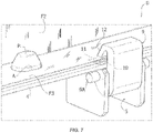
- Figures 5 , 6 and 7 illustrate a second embodiment providing, analogously to the one of figures 3, 4 , mutual engagement elements for centering the panel 1 in the horizontal plane, including one or more preferably conical or however tapered reference pins P, projecting upwards by a supporting stirrup 5 fastened to the wall 4A of the respective profile 4 and one or more slots A formed in the flange F3 of the frame F of the photovoltaic solar panel for engaging the pins P.
- a pin P has a base section with elongated shape, so as to engage the whole length of the slot A and to refer the panel 1 in two horizontal directions orthogonal therebetween.
- the quick locking device B comprises a blocking element B1 constituted by an element 9, for example made of metal material and for example obtained by extrusion, which is assembled so as to revolve around a pin 9A ( figure 7 ) on the supporting stirrup 5.
- the element 9 has a portion 10 with a matching surface 11.
- the surface 11 is engaged by the lower flange F3 of the frame F of the panel during the lowering motion of the panel so as to cause a rotation of the blocking element B1 from the inoperative position illustrated in figure 5 , to the blocking operative position illustrated in figure 6 , wherein an upper lip 12 of the blocking element B1 engages the upper surface of the flange F3 by blocking it against the flange 4B and thus preventing any motion of the panel 1 in the vertical direction.
- the blocking element B1 is kept by a stopping element constituted by an elastic sheet 13, carried by the stirrup 5 and apt to engage a seat 14 of the element 9.
- the stopping element 13 is outside the engagement in the seat 14 and it is kept under a condition elastically deformed from the engagement against the outer surface 15 of the element 9.
- FIGS 8-10 illustrate an additional embodiment wherein the mutual engagement centering elements (pins P and slots A) can remain the same of figures 3, 4 or figures 5-7 , whereas the blocking element is implemented in a different way.
- the blocking element B1 is jointed by means of a pin 9 to the stirrup 5, so as to be able to swing from an inoperative position (illustrated in figure 8 ) to a blocking operative position, wherein a front mouth thereof 12 overlaps to the flange F3 of the photovoltaic solar panel 1.
- the rotation of the blocking element B1 is induced by toggle levers, including a rod 93, which is connected in jointed way at its ends to the element B1 and to a lever 90.
- the lever 90 carries a pin 91 which can swing and slide within a slot 92 of the stirrup 5. Under the inoperative condition of the blocking element B1, the lever 90 has a portion 94 projecting upwards with respect to the resting plane of the photovoltaic solar panel on the profiles 4. When the panel 1 is lowered above the profiles 4, it pushes downwards the portion 94 of the lever 90. The lever 90 is then obliged to rotate around the axis of its own pin 91 so as to cause, by means of the rod 93 the rotation of the element B1 in the blocking position.
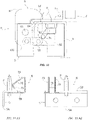
- Figures 11A1 and 11A2 illustrate a side view and a front view of an additional embodiment, wherein the quick locking device B comprises mutual engagement centering elements in form of a pin P and a slot A (the slot not visible in these figures) identical to those of figures 3, 4 or figures 5-7 , and a blocking element B1 in form of a U-like bent metal tendon, with a base portion anchored to a flange 5B of a stirrup 5 fastened to the (not illustrated) profile 4, an elastically deformable portion 70, apt to perform the cam function during the lowering motion of the panel 1, and a hook-like terminal portion 71 apt to overlap to the (not illustrated in such figures) flange F3, by blocking it above the flange 4B of the profile 4, when the panel 1 has reached its final position in contact with the flange 4B.
- the quick locking device B comprises mutual engagement centering elements in form of a pin P and a slot A (the slot not visible in these figures) identical to those of figures 3, 4 or figures 5-7
- Figure 11B shows a variant wherein the blocking element B1 is partially covered by a flange 50 of the stirrup 5, which has the function of reinforcement with respect to possible deformations upwards of the portion 70 of the blocking element B1 when, after the connection with the panel 1, an action tending to raise the panel itself is exerted.
- the plate 5 can also be obtained as one single piece with the profile 4.
- Figure 11C shows an additional variant wherein a containment stirrup 51 is engaged above the root of the deformable portion 70, the stirrup being constituted by a U-like bent metal tendon, arranged like a bridge above the portion 70, with the ends fastened to the stirrup 5.
- the stirrup 51 has the function of reinforcement with respect to possible deformations upwards of the portion 70 of the blocking element B1 when, after the connection with the panel 1, an action tending to raise the panel itself is exerted.
- FIGS 12 to 17 show a seventh embodiment of a device according to the present invention.
- a quick locking device B comprises a stirrup 5 which could be fastened to the support structure S.
- the stirrup 5 provides a base flange 5B having fastening means H - for example holes for the positioning of screws, rivets or equivalent elements for the fastening to the support structure S.
- the base flange 5B preferably implemented as flat sheet, defines a supporting plane which receives the photovoltaic panels and has two opposite ends 5C folded on themselves, ending with respective reinforcing flanges 50 to form two substantially "C"-shaped seats faced therebetween.
- Each reinforcing flange 50 forms an angle ⁇ with the extremal wall of the corresponding end 5C.
- the angle ⁇ is comprised between 45° and 75°. Still more preferably it is about 60°.
- the device B comprises two blocking elements B1, one at each end 5C.
- Each blocking element B comprises a respective sheet-like elastic element 70, 71 shaped so as to place within said "C"-like seats and having a terminal portion 71 at least partially projecting from the reinforcing flange 50.
- the sheet-like elastic element is fastened to the stirrup 5, for example by means of rivets R.
- rivets R Of course, it is to be meant that other fastening modes could be provided.
- the quick locking device B can house contemporarily two photovoltaic panels 1, by allowing the locking at the two opposite ends 5C. This simplifies greatly the installation process on the support structure S and allows to reduce the use of materials and to keep low the installation costs.
- the quick locking device B can further comprise one or more matching elements O, preferably arranged in central position on the base flange 5B.
- the matching elements O are implemented by means of a portion of base flange 5B partially cut and folded upwards.
- one or more mutual engagement elements P can be provided, shaped so as to result apt to cooperate, during installation, with respective slots A implemented on the photovoltaic panels 1.
- each quick locking device B provides one single matching element P, implemented at one of the two ends 5C.
- the presence of the matching element P only on one side of the device can be advantageous in terms of assembly, as it will be described hereinafter.
- the solution can further provide two matching elements P, positioned in symmetrical position with respect to the centre of the base flange 5B, both of them implemented by means of a portion of base flange 5B partially cut and folded upwards.
- the mutual engagement elements P can advantageously be implemented by means of a portion of base flange 5B partially cut and folded upwards.
- the base flange 5B advantageously can include two slots A1 implemented at the terminal portions 71, to allow the lowering thereof during the engagement with the photovoltaic solar panel 1.
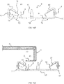
- figure 15A shows a starting initial position, wherein the photovoltaic panel 1 is positioned above the quick locking device B, in substantially parallel position and with the peripheral portion of the frame F aligned with the matching element O.
- a device provides to move the photovoltaic panel 1, by approaching it to the quick locking device B, only according to a rectilinear trajectory, according to a direction D orthogonal to the supporting plane defined by the flange 5B and which keeps it parallel to the flange 5b of the device B, as designated by the arrow D in figure 15B .
- the term "rectilinear trajectory” wishes to designate a "mainly rectilinear” trajectory, that is “overall rectilinear” unless shifting with much reduced width than the overall shifting and due, for example, to the discretization of the trajectory itself.
- translation motions of the panel along other directions, rotation motions of the same and combined motions, when the panel is in the immediate proximity of the blocking device B are neither provided nor required.
- the flange F3 of the photovoltaic panel 1 will engage the elastic portion 70 of the blocking element B1.
- the elastic portion 70 will deform, by bending in the direction designated by the arrow T1 in figure 15B .
- the blocking element B1 when the photovoltaic solar panel 1 reaches its final position in contact with the flange 5B, the blocking element B1 will tend to return to its original resting condition, at least as much as it is allowed it by the interference with the flange F3 of the panel itself.
- the terminal portion 71 of the blocking element B1 engages the flange F3, by blocking it automatically in the final blocking position with the force required for keeping the photovoltaic panel 1 in contact with the structure S, under all operative conditions provided for the structure S.
- the subsequent figure 16 describes by way of example the same procedure for installing a photovoltaic panel 1, however performed at the opposite end of the locking device B.
- the operation remains substantially identical. According to what illustrated, even if by way of example, the device does not provide on this side any mutual engagement element P, therefore no cooperation with the centering slots A in case present on the flange F3 of the photovoltaic panel 1 is provided.
- the subsequent figure 17 shows the way in which a single quick locking device B according to such seventh embodiment could be used to receive contemporarily two photovoltaic panels 1, in specular and symmetrical position therebetween.
- FIG. 18 an example of support structure S, with the beam 2 and the profiles 4, can also be seen in figures 18 and 19 .
- the structure S comprises supporting uprights 32, driven in the ground (only one thereof is visible in figure), which carry the beam by means of joining devices, of any known type, including means for making the beam 2 to swing around its longitudinal axis, with the purpose of obtaining the solar tracking motion of the photovoltaic solar panels intended to be carried by the structure S.
- figure 19 shows, by way of example, the way in which the quick locking devices according to the present invention could be assembled thereon, and in the specific example of figure, those according to the now described seventh embodiment.
- the quick locking devices B are, as already described, so as each one to provide a single mutual engagement element P, on only one of the two sides intended to receive respective photovoltaic panels.
- the quick locking devices B are assembled by alternating the orientation thereof, so as to have as a whole an alternation even in the position of the mutual engagement elements P.
- This characteristic assembly mode advantageously allows to 'relax' the mechanical tolerances and the yokes during the approaching of the panels and then to allow an easier assembly of the same even should the alignments not be extremely precise.
- the blocking device B can be brought again in the inoperative position thereof, to remove the photovoltaic solar panel, for example to proceed with maintenance procedures or a replacement thereof.
- the quick locking device is irreversible, that it does not allow the disassembling of the panel 1 anymore, once this has been locked, unless by destructing the connecting device.
- the above-described device can be used, if it is preferred, to perform manually the procedure for installing the photovoltaic solar panels 1 on their support structure S.
- the device of the invention can also be used to perform the installation procedure automatically.
- the device according to the invention reduces drastically the time required to perform the installation, it guarantees to obtain a high and uniform precision in positioning the photovoltaic solar panels 1 and it guarantees a correct blocking of the panels under the installed condition.
- the device according to the invention can also be used to perform manually the installation in simple and easy way for the operators.
Landscapes
- Engineering & Computer Science (AREA)
- Mechanical Engineering (AREA)
- Combustion & Propulsion (AREA)
- Sustainable Energy (AREA)
- General Engineering & Computer Science (AREA)
- Chemical & Material Sciences (AREA)
- Physics & Mathematics (AREA)
- Life Sciences & Earth Sciences (AREA)
- Sustainable Development (AREA)
- Thermal Sciences (AREA)
- Structural Engineering (AREA)
- Civil Engineering (AREA)
- Architecture (AREA)
- Robotics (AREA)
- Photovoltaic Devices (AREA)
- Roof Covering Using Slabs Or Stiff Sheets (AREA)
- Control Of Position Or Direction (AREA)
Claims (8)
- Schnellverschlussvorrichtung (B) zum Verbinden mindestens eines Photovoltaik-Solarpaneels (1) mit einer Tragstruktur (S), wobei die Vorrichtung so ausgestaltet ist, dass das mindestens eine Photovoltaik-Solarpaneel (1) auf der Tragstruktur (S) installiert werden kann, indem es sich der Tragstruktur (S) mit einer Absenkbewegung von oben nur gemäß einer geradlinigen Bahn orthogonal zu einer durch die Verschlussvorrichtung (B) definierten Tragebene des Photovoltaik-Solarpaneels (1) nähert, bis es eine Endposition erreicht, in der die Verschlussvorrichtung (B) das Photovoltaik-Solarpaneel (1) automatisch auf der Tragstruktur (S) blockiert, die Schnellverschlussvorrichtung (B) mindestens ein Blockierelement (B1) umfasst, das so ausgestaltet ist, dass es sich während der Installation automatisch von einer freigegebenen Ruheposition in eine blockierende Betriebsposition verschieben kann, nachdem das Photovoltaik-Solarpaneel (1) daran angreift, wenn das Photovoltaik-Solarpaneel (1) seine endgültige Position erreicht,wobei die Schnellverschlussvorrichtung (B) einen Bügel (5) mit einem Basisflansch (5B) umfasst, der Befestigungsmittel (H) für die Befestigung an der Tragstruktur (S) aufweist, wobei der Basisflansch (5B) zwei gegenüberliegende umgebogene Enden (5C) hat, die mit jeweiligen Verstärkungsflanschen (50) enden, um zwei im Wesentlichen "C"-förmige gegenüberliegende Sitze zu bilden,wobei die Vorrichtung dadurch gekennzeichnet ist, dass sie zwei Blockierelemente (B1) umfasst, eines an jedem Ende, wobei jedes Blockierelement (B1) ein jeweiliges folienartiges elastisches Element (70, 71) umfasst, das so geformt ist, dass es innerhalb der "C"-artigen Sitze platziert werden kann, und einen Endabschnitt (71) aufweist, der zumindest teilweise von dem Verstärkungsflansch (50) vorsteht.
- Schnellverschlussvorrichtung (B) nach Anspruch 1 ferner umfassend gegenseitige Eingriffselemente (P), die so ausgestaltet sind, dass sie während der Installation mit entsprechenden Eingriffselementen (A) des Photovoltaik-Solarpaneels (1) zusammenwirken, um das Photovoltaik-Solarpaneel (1) auf der Trägerstruktur (S) zu zentrieren.
- Schnellverschlussvorrichtung (B) nach Anspruch 2, wobei die gegenseitigen Eingriffselemente einen Referenzzapfen (P) umfassen und die Eingriffselemente (A) des Paneels (1) eine Öffnung (A) umfassen, so dass der Referenzzapfen (P) in der endgültigen Position des Photovoltaik-Solarpaneels (1) auf der Tragstruktur (S) in der Öffnung (A) aufgenommen werden kann.
- Schnellverschlussvorrichtung (B) nach einem der Ansprüche 1 bis 3, wobei der Basisflansch (5B) zwei Schlitze (A1) umfasst, die an den Endabschnitten (71) ausgebildet sind, um das Absenken derselben während des Eingreifens mit dem Photovoltaik-Solarpaneel (1) zu ermöglichen.
- Schnellverschlussvorrichtung (B) nach einem der Ansprüche 1 bis 4, die ferner ein oder mehrere Passelemente (O) umfasst, die in zentraler Position auf dem Basisflansch (5B) angeordnet sind und dazu geeignet sind, während der Installation eine Gehäuseführung für die Paneele (1) zu bilden.
- Schnellverschlussvorrichtung (B) nach Anspruch 5, wobei das eine oder die mehreren Passelemente (O) durch einen Teil des Basisflansches (5B), der teilweise abgeschnitten und nach oben gefaltet ist, ausgebildet sind.
- Die Schnellverschlussvorrichtung (B) nach einem der Ansprüche 1 bis 6, ferner umfassend mindestens ein gegenseitiges Eingriffselement (P), das geeignet ist, mit einem jeweiligen Schlitz (A), der auf dem Photovoltaik-Paneel (1) ausgebildet ist, während der Installation zusammenzuwirken.
- Schnellverschlussvorrichtung (B) nach Anspruch 7, wobei das mindestens eine gegenseitige Eingriffselement (P) mittels eines Abschnitts des Basisflansches (5B) ausgebildet ist, der teilweise geschnitten und nach oben gefaltet ist.
Applications Claiming Priority (2)
| Application Number | Priority Date | Filing Date | Title |
|---|---|---|---|
| IT201700130000 | 2017-11-14 | ||
| PCT/IB2018/058731 WO2019097359A1 (en) | 2017-11-14 | 2018-11-07 | Quick locking device for connecting photovoltaic solar panels to a support structure |
Publications (2)
| Publication Number | Publication Date |
|---|---|
| EP3711158A1 EP3711158A1 (de) | 2020-09-23 |
| EP3711158B1 true EP3711158B1 (de) | 2022-10-26 |
Family
ID=61731736
Family Applications (2)
| Application Number | Title | Priority Date | Filing Date |
|---|---|---|---|
| EP18807422.3A Active EP3711157B1 (de) | 2017-11-14 | 2018-11-02 | System zur installation von photovoltaischen solarpaneelen in einem aussenbereich |
| EP18811651.1A Active EP3711158B1 (de) | 2017-11-14 | 2018-11-07 | Schnellverschlussvorrichtung zum verbinden von fotovoltaischen solarpaneelen mit einer tragstruktur |
Family Applications Before (1)
| Application Number | Title | Priority Date | Filing Date |
|---|---|---|---|
| EP18807422.3A Active EP3711157B1 (de) | 2017-11-14 | 2018-11-02 | System zur installation von photovoltaischen solarpaneelen in einem aussenbereich |
Country Status (9)
| Country | Link |
|---|---|
| US (1) | US11245353B2 (de) |
| EP (2) | EP3711157B1 (de) |
| AU (1) | AU2018369820B2 (de) |
| CA (1) | CA3079669A1 (de) |
| CL (1) | CL2020001237A1 (de) |
| ES (2) | ES2930375T3 (de) |
| MX (1) | MX2020007200A (de) |
| PT (1) | PT3711157T (de) |
| WO (2) | WO2019097348A1 (de) |
Cited By (1)
| Publication number | Priority date | Publication date | Assignee | Title |
|---|---|---|---|---|
| EP4572134A1 (de) * | 2023-12-14 | 2025-06-18 | Impianti Elettrici Alpa Di Lorenzato Paride Gino | Befestigungsvorrichtung für fotovoltaische paneele |
Families Citing this family (45)
| Publication number | Priority date | Publication date | Assignee | Title |
|---|---|---|---|---|
| US11235471B2 (en) * | 2018-05-22 | 2022-02-01 | Uatc, Llc | Automated cleaning systems for autonomous vehicles |
| EP4121253A4 (de) | 2020-03-20 | 2024-04-17 | Rosendin Electric, Inc. | Autonomes bodenfahrzeug zur solarmodulinstallation |
| WO2021229387A2 (en) * | 2020-05-11 | 2021-11-18 | Comau S.P.A. | Method and system for assembling and installing arrays of photovoltaic solar panels in an outdoor field |
| WO2021252427A1 (en) * | 2020-06-08 | 2021-12-16 | Re2, Inc. | Robotic manipulation of pv modules |
| US12334868B2 (en) | 2020-08-28 | 2025-06-17 | The Aes Corporation | Solar panel handling system |
| US12184231B2 (en) | 2020-08-28 | 2024-12-31 | The Aes Corporation | Solar panel handling system |
| WO2022112921A1 (en) * | 2020-11-24 | 2022-06-02 | Comau S.P.A. | Method for outdoor installation of an array of solar converters, and carriage used in the method |
| IT202100001178A1 (it) | 2021-01-22 | 2022-07-22 | Comau Spa | "sistema di pannelli solari fotovoltaici" |
| IL305509A (en) | 2021-03-01 | 2023-10-01 | Planted Solar Inc | Methods and systems for assembling a solar power plant |
| US11964860B2 (en) * | 2021-06-08 | 2024-04-23 | Bailey Specialty Cranes and Aerials, LLC | Solar panel direct-motion installation apparatus |
| US11817819B2 (en) * | 2021-07-13 | 2023-11-14 | Array Technologies, Inc. | Automated attachment of solar components |
| US11999284B2 (en) | 2021-09-01 | 2024-06-04 | Terabase Energy, Inc. | Solar table mobile transport |
| IT202100028058A1 (it) * | 2021-11-04 | 2023-05-04 | Enel Green Power Spa | Sistema mobile per assemblare telai di supporto per schiere di pannelli fotovoltaici e per installare detti telai di supporto su una struttura di ricezione |
| AU2022404977A1 (en) * | 2021-12-07 | 2024-06-06 | The Aes Corporation | Solar panel handling system |
| US11833677B2 (en) | 2022-04-20 | 2023-12-05 | Inventus Holdings Llc | Semi-autonomous exoskeleton apparatus for solar panel installation |
| DK181476B1 (en) * | 2022-06-07 | 2024-02-22 | Nordic Solar As | Mounting system for solar panel, solar panel comprising the system and method for mounting solar panel sheets on a solar panel |
| WO2024020062A2 (en) * | 2022-07-19 | 2024-01-25 | Oshkosh Corporation | Solar panel installation system |
| US20240051145A1 (en) * | 2022-08-11 | 2024-02-15 | The Aes Corporation | Autonomous solar installation using artificial intelligence |
| EP4584881A1 (de) * | 2022-09-06 | 2025-07-16 | The AES Corporation | Fabrik zur vormontage von solarpaneelen |
| WO2024091634A1 (en) * | 2022-10-26 | 2024-05-02 | Array Tech, Inc. | Photovoltaic panel distribution system |
| US11938576B1 (en) | 2022-12-20 | 2024-03-26 | Terabase Energy, Inc. | Systems and methods for threading a torque tube through U-bolt and module rail devices |
| US12305353B2 (en) * | 2022-12-21 | 2025-05-20 | Built Robotics Inc. | Pile platforms for autonomous pile driver vehicle |
| US11788247B1 (en) | 2022-12-21 | 2023-10-17 | Built Robotics Inc. | Basket assembly operation for autonomous pile driving system |
| US12216468B2 (en) | 2022-12-21 | 2025-02-04 | Built Robotics Inc. | Quality control operation for autonomous pile driving system |
| US11822342B1 (en) | 2022-12-21 | 2023-11-21 | Built Robotics Inc. | Obstacle map for autonomous pile driving system |
| US12129624B2 (en) | 2022-12-21 | 2024-10-29 | Built Robotics Inc. | Pile manipulation tool for autonomous pile driver vehicle |
| US20240235470A1 (en) | 2023-01-09 | 2024-07-11 | Sarcos Corp. | Auto-Engaging Electrical Connections for Solar Panels |
| US12244262B2 (en) | 2023-01-09 | 2025-03-04 | Sarcos Corp. | Capture and support mount for retaining installed solar panels |
| US12466066B2 (en) | 2023-05-04 | 2025-11-11 | Sarcos Corp. | Solar panel dispensing device with vertical solar panel hopper loading and dispensing |
| DK181824B1 (en) * | 2023-06-13 | 2025-01-30 | Eni Dev Aps | A method for installing a photovoltaic solar panel |
| WO2025035088A1 (en) * | 2023-08-09 | 2025-02-13 | Gritt Robotics Inc. | System and method for mounting objects across a non-uniform outdoor terrain |
| WO2025038658A2 (en) * | 2023-08-14 | 2025-02-20 | Vermeer Manufacturing Company | Material handling apparatus and methods of using the same |
| CN117263026B (zh) * | 2023-11-20 | 2024-02-13 | 上海博珖机器人有限公司 | 定位系统、定位方法、光伏阵列半成品安装设备及方法 |
| CN117446493B (zh) * | 2023-12-25 | 2024-03-26 | 湖南凯之成智能装备有限公司 | 铺装设备和光伏板的安装方法 |
| US12617639B2 (en) | 2024-01-08 | 2026-05-05 | Sarcos Corp. | Dispensing hopper and presentation system for overhead installation of solar panels for a solar tracking system |
| US12542513B2 (en) | 2024-01-08 | 2026-02-03 | Sarcos Corp. | Torque tube clamps for automated solar panel installation |
| US12570001B2 (en) * | 2024-01-08 | 2026-03-10 | Sarcos Corp. | Support clamp installation vehicles as part of a solar panel installation system for a solar tracking system |
| US12413179B1 (en) | 2024-03-07 | 2025-09-09 | Planted Solar, Inc. | Systems and methods for solar module assembly |
| DE102024107693B3 (de) * | 2024-03-18 | 2025-07-31 | Vecon Gmbh | Transport- und Montagevorrichtung für Fotovoltaiksegmente und Verfahren zur Montage von Fotovoltaiksegmenten |
| DE202024102769U1 (de) | 2024-05-28 | 2024-07-22 | Miloš Horinka | Mobile Einrichtung zur Montage von Panelblöcken |
| CN118636140B (zh) * | 2024-06-11 | 2025-03-04 | 同济大学 | 基于机器视觉的建筑板材安装方法、系统和存储介质 |
| EP4672595A1 (de) | 2024-06-28 | 2025-12-31 | HORINKA, Milos | Mobile vorrichtung zur montage paneelblöcken |
| EP4744150A1 (de) * | 2024-09-27 | 2026-05-20 | Nrg Tech Ltd | System und verfahren zum einrichten eines autonomen fotovoltaischen kraftwerks |
| WO2026085061A1 (en) * | 2024-10-14 | 2026-04-23 | Vermeer Manufacturing Company | Material handling apparatus and methods of using the same |
| CN119995476A (zh) * | 2025-03-20 | 2025-05-13 | 湖北能源集团西北新能源发展有限公司 | 具备榫卯定位与抗撕裂卯眼安装孔的光伏组件自动铺设方法 |
Family Cites Families (16)
| Publication number | Priority date | Publication date | Assignee | Title |
|---|---|---|---|---|
| US4964062A (en) * | 1988-02-16 | 1990-10-16 | Ubhayakar Shivadev K | Robotic arm systems |
| EP0719459A1 (de) * | 1993-09-16 | 1996-07-03 | Blue Planet Ag | Solar-dachziegel/dachstein |
| EP2263964A3 (de) * | 2009-06-19 | 2011-09-14 | Siegfried Riebsamen | Montagefahrzeug für Glas- bzw. Solarmodule |
| WO2010145844A2 (de) * | 2009-06-19 | 2010-12-23 | Gehrlicher Solar Ag | Vorrichtung zum handhaben und positionieren von grossformatigen solarmodulen |
| EP2576288A1 (de) * | 2010-06-02 | 2013-04-10 | Kiener Maschinenbau GmbH | Verfahren zur automatisierten montage von modulen an aufnahmeeinrichtungen, insbesondere solarmodulen auf aufständerungen sowie mobile montageeinrichtungen für solche module |
| US20120027550A1 (en) | 2010-07-29 | 2012-02-02 | John Bellacicco | Automated installation system for and method of deployment of photovoltaic solar panels |
| DE102010038054A1 (de) | 2010-09-08 | 2012-03-08 | Reis Group Holding Gmbh & Co. Kg | Verfahren und Fahrzeug zum Handhaben von Solarzellenmodulen |
| EP2686224A2 (de) * | 2011-03-17 | 2014-01-22 | Raytheon Company | Mobiles robotisches flaches transportfahrzeug |
| CN103917832A (zh) * | 2011-07-19 | 2014-07-09 | 布瑞特摩尔集团公司 | 光伏模块的安装系统 |
| US20130240008A1 (en) * | 2012-03-16 | 2013-09-19 | Christopher Baker | System and method for mounting photovoltaic modules |
| US9352941B2 (en) * | 2012-03-20 | 2016-05-31 | Alion Energy, Inc. | Gantry crane vehicles and methods for photovoltaic arrays |
| KR101954196B1 (ko) * | 2012-04-25 | 2019-03-05 | 엘지전자 주식회사 | 태양 전지 모듈 및 이를 포함하는 태양광 발전 장치 |
| US8567134B1 (en) * | 2012-06-29 | 2013-10-29 | Sunpower Corporation | Snap-in and progressive locking photovoltaic module |
| US9708139B2 (en) * | 2014-04-28 | 2017-07-18 | Clean Energy Factory Co., Ltd. | Solar power plant construction method |
| US11241799B2 (en) * | 2016-03-18 | 2022-02-08 | Intelli-Products Inc. | Solar energy array robotic assembly |
| CN109964403B (zh) * | 2016-11-01 | 2020-12-04 | 斯诺乐科技有限责任公司 | 用于去除碎片的系统和方法 |
-
2018
- 2018-11-02 ES ES18807422T patent/ES2930375T3/es active Active
- 2018-11-02 CA CA3079669A patent/CA3079669A1/en active Pending
- 2018-11-02 PT PT188074223T patent/PT3711157T/pt unknown
- 2018-11-02 WO PCT/IB2018/058621 patent/WO2019097348A1/en not_active Ceased
- 2018-11-02 AU AU2018369820A patent/AU2018369820B2/en active Active
- 2018-11-02 MX MX2020007200A patent/MX2020007200A/es unknown
- 2018-11-02 US US16/760,668 patent/US11245353B2/en active Active
- 2018-11-02 EP EP18807422.3A patent/EP3711157B1/de active Active
- 2018-11-07 EP EP18811651.1A patent/EP3711158B1/de active Active
- 2018-11-07 WO PCT/IB2018/058731 patent/WO2019097359A1/en not_active Ceased
- 2018-11-07 ES ES18811651T patent/ES2935612T3/es active Active
-
2020
- 2020-05-08 CL CL2020001237A patent/CL2020001237A1/es unknown
Cited By (1)
| Publication number | Priority date | Publication date | Assignee | Title |
|---|---|---|---|---|
| EP4572134A1 (de) * | 2023-12-14 | 2025-06-18 | Impianti Elettrici Alpa Di Lorenzato Paride Gino | Befestigungsvorrichtung für fotovoltaische paneele |
Also Published As
| Publication number | Publication date |
|---|---|
| US20200350850A1 (en) | 2020-11-05 |
| PT3711157T (pt) | 2022-11-21 |
| US11245353B2 (en) | 2022-02-08 |
| EP3711158A1 (de) | 2020-09-23 |
| ES2935612T3 (es) | 2023-03-08 |
| AU2018369820A1 (en) | 2020-05-07 |
| CL2020001237A1 (es) | 2020-11-13 |
| CA3079669A1 (en) | 2019-05-23 |
| WO2019097348A1 (en) | 2019-05-23 |
| ES2930375T3 (es) | 2022-12-09 |
| EP3711157B1 (de) | 2022-09-28 |
| WO2019097359A1 (en) | 2019-05-23 |
| EP3711157A1 (de) | 2020-09-23 |
| MX2020007200A (es) | 2021-01-20 |
| AU2018369820B2 (en) | 2023-03-16 |
| BR112020009286A2 (pt) | 2020-10-27 |
Similar Documents
| Publication | Publication Date | Title |
|---|---|---|
| EP3711158A1 (de) | Schnellverschlussvorrichtung zum verbinden von fotovoltaischen solarpaneelen mit einer tragstruktur | |
| US10720877B2 (en) | Photovoltaic mounting system for solar tracker array | |
| EP4072008A1 (de) | Solartracker mit in reihen angeordneten orientierbaren solarpaneelen | |
| KR102192480B1 (ko) | 태양광패널 설치용 구조물 | |
| US20170126168A1 (en) | Grid-lite roof system for solar panel installations | |
| EP2762654A1 (de) | Stützstruktur für solarlichtdachplatten | |
| EP3134643B1 (de) | Verfahren und werkzeug zur montage von turmelemente | |
| US20150288324A1 (en) | Support structure for solar modules | |
| US20220205429A1 (en) | A nacelle of a wind turbine | |
| US9036236B2 (en) | Mirror module | |
| EP2333453B1 (de) | Tragrahmen und Vorrichtung zum Befestigen von Solarpaneelen auf dem Tragrahmen | |
| EP3204699B1 (de) | Montageschiene, system zum montieren eines solarpaneels und verfahren zum montieren mindestens zwei solarpaneele | |
| EP2385327A1 (de) | Einachsiger Sonnenfolger | |
| CA2912851C (en) | Trusses for use in building construction and methods of installing same | |
| EP4151561A1 (de) | Werkzeug zum sichern und umdrehen zur montage von fotovoltaischen sonnenfolgerabschnitten, system und zugehöriges montageverfahren | |
| EP3404159B1 (de) | Träger zur verwendung im gebäudebau | |
| EP4184017A1 (de) | Dachbefestigungskonsole | |
| WO2016152680A1 (ja) | 太陽電池モジュール用取付具及び太陽電池モジュールの取付方法 | |
| KR102022612B1 (ko) | 조립식 온실 및 이의 시공방법 | |
| EP3029210A1 (de) | Seismische fixierungsvorrichtung, insbesondere für fertighäuser | |
| CN108422360A (zh) | 一种装配钢筋桁架楼承板的装置的夹具 | |
| US20120312941A1 (en) | Mounting system and method for mounting a curved panel to a frame | |
| KR101060186B1 (ko) | 거푸집 승강장치용 전환유니트 | |
| ES3039548T3 (en) | Anchoring bracket | |
| CN117414545B (zh) | 一种防坠落保护装置及保护系统 |
Legal Events
| Date | Code | Title | Description |
|---|---|---|---|
| STAA | Information on the status of an ep patent application or granted ep patent |
Free format text: STATUS: UNKNOWN |
|
| STAA | Information on the status of an ep patent application or granted ep patent |
Free format text: STATUS: THE INTERNATIONAL PUBLICATION HAS BEEN MADE |
|
| PUAI | Public reference made under article 153(3) epc to a published international application that has entered the european phase |
Free format text: ORIGINAL CODE: 0009012 |
|
| STAA | Information on the status of an ep patent application or granted ep patent |
Free format text: STATUS: REQUEST FOR EXAMINATION WAS MADE |
|
| 17P | Request for examination filed |
Effective date: 20200317 |
|
| AK | Designated contracting states |
Kind code of ref document: A1 Designated state(s): AL AT BE BG CH CY CZ DE DK EE ES FI FR GB GR HR HU IE IS IT LI LT LU LV MC MK MT NL NO PL PT RO RS SE SI SK SM TR |
|
| AX | Request for extension of the european patent |
Extension state: BA ME |
|
| DAV | Request for validation of the european patent (deleted) | ||
| DAX | Request for extension of the european patent (deleted) | ||
| RIN1 | Information on inventor provided before grant (corrected) |
Inventor name: BECCARISI, FRANCESCO Inventor name: STERPILLA, DIEGO Inventor name: STRAZZA, ALFONSO Inventor name: DI STEFANO, GIOVANNI |
|
| RIN1 | Information on inventor provided before grant (corrected) |
Inventor name: DI STEFANO, GIOVANNI Inventor name: BECCARISI, FRANCESCO Inventor name: STERPILLA, DIEGO Inventor name: STRAZZA, ALFONSO |
|
| STAA | Information on the status of an ep patent application or granted ep patent |
Free format text: STATUS: EXAMINATION IS IN PROGRESS |
|
| 17Q | First examination report despatched |
Effective date: 20210525 |
|
| GRAP | Despatch of communication of intention to grant a patent |
Free format text: ORIGINAL CODE: EPIDOSNIGR1 |
|
| STAA | Information on the status of an ep patent application or granted ep patent |
Free format text: STATUS: GRANT OF PATENT IS INTENDED |
|
| INTG | Intention to grant announced |
Effective date: 20220527 |
|
| GRAS | Grant fee paid |
Free format text: ORIGINAL CODE: EPIDOSNIGR3 |
|
| GRAA | (expected) grant |
Free format text: ORIGINAL CODE: 0009210 |
|
| STAA | Information on the status of an ep patent application or granted ep patent |
Free format text: STATUS: THE PATENT HAS BEEN GRANTED |
|
| AK | Designated contracting states |
Kind code of ref document: B1 Designated state(s): AL AT BE BG CH CY CZ DE DK EE ES FI FR GB GR HR HU IE IS IT LI LT LU LV MC MK MT NL NO PL PT RO RS SE SI SK SM TR |
|
| REG | Reference to a national code |
Ref country code: GB Ref legal event code: FG4D |
|
| REG | Reference to a national code |
Ref country code: CH Ref legal event code: EP |
|
| REG | Reference to a national code |
Ref country code: AT Ref legal event code: REF Ref document number: 1527810 Country of ref document: AT Kind code of ref document: T Effective date: 20221115 |
|
| REG | Reference to a national code |
Ref country code: DE Ref legal event code: R096 Ref document number: 602018042336 Country of ref document: DE |
|
| REG | Reference to a national code |
Ref country code: IE Ref legal event code: FG4D |
|
| REG | Reference to a national code |
Ref country code: LT Ref legal event code: MG9D |
|
| REG | Reference to a national code |
Ref country code: NL Ref legal event code: MP Effective date: 20221026 |
|
| REG | Reference to a national code |
Ref country code: ES Ref legal event code: FG2A Ref document number: 2935612 Country of ref document: ES Kind code of ref document: T3 Effective date: 20230308 |
|
| REG | Reference to a national code |
Ref country code: AT Ref legal event code: MK05 Ref document number: 1527810 Country of ref document: AT Kind code of ref document: T Effective date: 20221026 |
|
| REG | Reference to a national code |
Ref country code: GR Ref legal event code: EP Ref document number: 20230400116 Country of ref document: GR Effective date: 20230307 |
|
| PG25 | Lapsed in a contracting state [announced via postgrant information from national office to epo] |
Ref country code: NL Free format text: LAPSE BECAUSE OF FAILURE TO SUBMIT A TRANSLATION OF THE DESCRIPTION OR TO PAY THE FEE WITHIN THE PRESCRIBED TIME-LIMIT Effective date: 20221026 |
|
| PG25 | Lapsed in a contracting state [announced via postgrant information from national office to epo] |
Ref country code: SE Free format text: LAPSE BECAUSE OF FAILURE TO SUBMIT A TRANSLATION OF THE DESCRIPTION OR TO PAY THE FEE WITHIN THE PRESCRIBED TIME-LIMIT Effective date: 20221026 Ref country code: PT Free format text: LAPSE BECAUSE OF FAILURE TO SUBMIT A TRANSLATION OF THE DESCRIPTION OR TO PAY THE FEE WITHIN THE PRESCRIBED TIME-LIMIT Effective date: 20230227 Ref country code: NO Free format text: LAPSE BECAUSE OF FAILURE TO SUBMIT A TRANSLATION OF THE DESCRIPTION OR TO PAY THE FEE WITHIN THE PRESCRIBED TIME-LIMIT Effective date: 20230126 Ref country code: LT Free format text: LAPSE BECAUSE OF FAILURE TO SUBMIT A TRANSLATION OF THE DESCRIPTION OR TO PAY THE FEE WITHIN THE PRESCRIBED TIME-LIMIT Effective date: 20221026 Ref country code: FI Free format text: LAPSE BECAUSE OF FAILURE TO SUBMIT A TRANSLATION OF THE DESCRIPTION OR TO PAY THE FEE WITHIN THE PRESCRIBED TIME-LIMIT Effective date: 20221026 Ref country code: AT Free format text: LAPSE BECAUSE OF FAILURE TO SUBMIT A TRANSLATION OF THE DESCRIPTION OR TO PAY THE FEE WITHIN THE PRESCRIBED TIME-LIMIT Effective date: 20221026 |
|
| PG25 | Lapsed in a contracting state [announced via postgrant information from national office to epo] |
Ref country code: RS Free format text: LAPSE BECAUSE OF FAILURE TO SUBMIT A TRANSLATION OF THE DESCRIPTION OR TO PAY THE FEE WITHIN THE PRESCRIBED TIME-LIMIT Effective date: 20221026 Ref country code: PL Free format text: LAPSE BECAUSE OF FAILURE TO SUBMIT A TRANSLATION OF THE DESCRIPTION OR TO PAY THE FEE WITHIN THE PRESCRIBED TIME-LIMIT Effective date: 20221026 Ref country code: LV Free format text: LAPSE BECAUSE OF FAILURE TO SUBMIT A TRANSLATION OF THE DESCRIPTION OR TO PAY THE FEE WITHIN THE PRESCRIBED TIME-LIMIT Effective date: 20221026 Ref country code: IS Free format text: LAPSE BECAUSE OF FAILURE TO SUBMIT A TRANSLATION OF THE DESCRIPTION OR TO PAY THE FEE WITHIN THE PRESCRIBED TIME-LIMIT Effective date: 20230226 Ref country code: HR Free format text: LAPSE BECAUSE OF FAILURE TO SUBMIT A TRANSLATION OF THE DESCRIPTION OR TO PAY THE FEE WITHIN THE PRESCRIBED TIME-LIMIT Effective date: 20221026 |
|
| REG | Reference to a national code |
Ref country code: DE Ref legal event code: R119 Ref document number: 602018042336 Country of ref document: DE |
|
| P01 | Opt-out of the competence of the unified patent court (upc) registered |
Effective date: 20230512 |
|
| REG | Reference to a national code |
Ref country code: CH Ref legal event code: PL |
|
| REG | Reference to a national code |
Ref country code: BE Ref legal event code: MM Effective date: 20221130 |
|
| PG25 | Lapsed in a contracting state [announced via postgrant information from national office to epo] |
Ref country code: SM Free format text: LAPSE BECAUSE OF FAILURE TO SUBMIT A TRANSLATION OF THE DESCRIPTION OR TO PAY THE FEE WITHIN THE PRESCRIBED TIME-LIMIT Effective date: 20221026 Ref country code: RO Free format text: LAPSE BECAUSE OF FAILURE TO SUBMIT A TRANSLATION OF THE DESCRIPTION OR TO PAY THE FEE WITHIN THE PRESCRIBED TIME-LIMIT Effective date: 20221026 Ref country code: MC Free format text: LAPSE BECAUSE OF FAILURE TO SUBMIT A TRANSLATION OF THE DESCRIPTION OR TO PAY THE FEE WITHIN THE PRESCRIBED TIME-LIMIT Effective date: 20221026 Ref country code: LI Free format text: LAPSE BECAUSE OF NON-PAYMENT OF DUE FEES Effective date: 20221130 Ref country code: EE Free format text: LAPSE BECAUSE OF FAILURE TO SUBMIT A TRANSLATION OF THE DESCRIPTION OR TO PAY THE FEE WITHIN THE PRESCRIBED TIME-LIMIT Effective date: 20221026 Ref country code: DK Free format text: LAPSE BECAUSE OF FAILURE TO SUBMIT A TRANSLATION OF THE DESCRIPTION OR TO PAY THE FEE WITHIN THE PRESCRIBED TIME-LIMIT Effective date: 20221026 Ref country code: CZ Free format text: LAPSE BECAUSE OF FAILURE TO SUBMIT A TRANSLATION OF THE DESCRIPTION OR TO PAY THE FEE WITHIN THE PRESCRIBED TIME-LIMIT Effective date: 20221026 Ref country code: CH Free format text: LAPSE BECAUSE OF NON-PAYMENT OF DUE FEES Effective date: 20221130 |
|
| PG25 | Lapsed in a contracting state [announced via postgrant information from national office to epo] |
Ref country code: SK Free format text: LAPSE BECAUSE OF FAILURE TO SUBMIT A TRANSLATION OF THE DESCRIPTION OR TO PAY THE FEE WITHIN THE PRESCRIBED TIME-LIMIT Effective date: 20221026 Ref country code: LU Free format text: LAPSE BECAUSE OF NON-PAYMENT OF DUE FEES Effective date: 20221107 Ref country code: AL Free format text: LAPSE BECAUSE OF FAILURE TO SUBMIT A TRANSLATION OF THE DESCRIPTION OR TO PAY THE FEE WITHIN THE PRESCRIBED TIME-LIMIT Effective date: 20221026 |
|
| PLBE | No opposition filed within time limit |
Free format text: ORIGINAL CODE: 0009261 |
|
| STAA | Information on the status of an ep patent application or granted ep patent |
Free format text: STATUS: NO OPPOSITION FILED WITHIN TIME LIMIT |
|
| GBPC | Gb: european patent ceased through non-payment of renewal fee |
Effective date: 20230126 |
|
| 26N | No opposition filed |
Effective date: 20230727 |
|
| PG25 | Lapsed in a contracting state [announced via postgrant information from national office to epo] |
Ref country code: IE Free format text: LAPSE BECAUSE OF NON-PAYMENT OF DUE FEES Effective date: 20221107 Ref country code: GB Free format text: LAPSE BECAUSE OF NON-PAYMENT OF DUE FEES Effective date: 20230126 Ref country code: DE Free format text: LAPSE BECAUSE OF NON-PAYMENT OF DUE FEES Effective date: 20230601 |
|
| PG25 | Lapsed in a contracting state [announced via postgrant information from national office to epo] |
Ref country code: SI Free format text: LAPSE BECAUSE OF FAILURE TO SUBMIT A TRANSLATION OF THE DESCRIPTION OR TO PAY THE FEE WITHIN THE PRESCRIBED TIME-LIMIT Effective date: 20221026 Ref country code: FR Free format text: LAPSE BECAUSE OF NON-PAYMENT OF DUE FEES Effective date: 20221226 Ref country code: BE Free format text: LAPSE BECAUSE OF NON-PAYMENT OF DUE FEES Effective date: 20221130 |
|
| PG25 | Lapsed in a contracting state [announced via postgrant information from national office to epo] |
Ref country code: CY Free format text: LAPSE BECAUSE OF FAILURE TO SUBMIT A TRANSLATION OF THE DESCRIPTION OR TO PAY THE FEE WITHIN THE PRESCRIBED TIME-LIMIT Effective date: 20221026 |
|
| PG25 | Lapsed in a contracting state [announced via postgrant information from national office to epo] |
Ref country code: MK Free format text: LAPSE BECAUSE OF FAILURE TO SUBMIT A TRANSLATION OF THE DESCRIPTION OR TO PAY THE FEE WITHIN THE PRESCRIBED TIME-LIMIT Effective date: 20221026 Ref country code: HU Free format text: LAPSE BECAUSE OF FAILURE TO SUBMIT A TRANSLATION OF THE DESCRIPTION OR TO PAY THE FEE WITHIN THE PRESCRIBED TIME-LIMIT; INVALID AB INITIO Effective date: 20181107 |
|
| PG25 | Lapsed in a contracting state [announced via postgrant information from national office to epo] |
Ref country code: BG Free format text: LAPSE BECAUSE OF FAILURE TO SUBMIT A TRANSLATION OF THE DESCRIPTION OR TO PAY THE FEE WITHIN THE PRESCRIBED TIME-LIMIT Effective date: 20221026 |
|
| PG25 | Lapsed in a contracting state [announced via postgrant information from national office to epo] |
Ref country code: MT Free format text: LAPSE BECAUSE OF FAILURE TO SUBMIT A TRANSLATION OF THE DESCRIPTION OR TO PAY THE FEE WITHIN THE PRESCRIBED TIME-LIMIT Effective date: 20221026 |
|
| PGFP | Annual fee paid to national office [announced via postgrant information from national office to epo] |
Ref country code: IT Payment date: 20250917 Year of fee payment: 8 |
|
| PGFP | Annual fee paid to national office [announced via postgrant information from national office to epo] |
Ref country code: TR Payment date: 20251017 Year of fee payment: 8 Ref country code: GR Payment date: 20251118 Year of fee payment: 8 |
|
| PGFP | Annual fee paid to national office [announced via postgrant information from national office to epo] |
Ref country code: ES Payment date: 20251209 Year of fee payment: 8 |