EP4072008A1 - Solartracker mit in reihen angeordneten orientierbaren solarpaneelen - Google Patents
Solartracker mit in reihen angeordneten orientierbaren solarpaneelen Download PDFInfo
- Publication number
- EP4072008A1 EP4072008A1 EP22382249.5A EP22382249A EP4072008A1 EP 4072008 A1 EP4072008 A1 EP 4072008A1 EP 22382249 A EP22382249 A EP 22382249A EP 4072008 A1 EP4072008 A1 EP 4072008A1
- Authority
- EP
- European Patent Office
- Prior art keywords
- rows
- solar panels
- transmission
- solar
- modules
- Prior art date
- Legal status (The legal status is an assumption and is not a legal conclusion. Google has not performed a legal analysis and makes no representation as to the accuracy of the status listed.)
- Pending
Links
Images


Classifications
-
- H—ELECTRICITY
- H02—GENERATION; CONVERSION OR DISTRIBUTION OF ELECTRIC POWER
- H02S—GENERATION OF ELECTRIC POWER BY CONVERSION OF INFRARED RADIATION, VISIBLE LIGHT OR ULTRAVIOLET LIGHT, e.g. USING PHOTOVOLTAIC [PV] MODULES
- H02S20/00—Supporting structures for PV modules
- H02S20/10—Supporting structures directly fixed to the ground
-
- H—ELECTRICITY
- H02—GENERATION; CONVERSION OR DISTRIBUTION OF ELECTRIC POWER
- H02S—GENERATION OF ELECTRIC POWER BY CONVERSION OF INFRARED RADIATION, VISIBLE LIGHT OR ULTRAVIOLET LIGHT, e.g. USING PHOTOVOLTAIC [PV] MODULES
- H02S20/00—Supporting structures for PV modules
- H02S20/30—Supporting structures being movable or adjustable, e.g. for angle adjustment
- H02S20/32—Supporting structures being movable or adjustable, e.g. for angle adjustment specially adapted for solar tracking
-
- F—MECHANICAL ENGINEERING; LIGHTING; HEATING; WEAPONS; BLASTING
- F24—HEATING; RANGES; VENTILATING
- F24S—SOLAR HEAT COLLECTORS; SOLAR HEAT SYSTEMS
- F24S30/00—Arrangements for moving or orienting solar heat collector modules
- F24S30/40—Arrangements for moving or orienting solar heat collector modules for rotary movement
- F24S30/42—Arrangements for moving or orienting solar heat collector modules for rotary movement with only one rotation axis
- F24S30/425—Horizontal axis
-
- F—MECHANICAL ENGINEERING; LIGHTING; HEATING; WEAPONS; BLASTING
- F24—HEATING; RANGES; VENTILATING
- F24S—SOLAR HEAT COLLECTORS; SOLAR HEAT SYSTEMS
- F24S25/00—Arrangement of stationary mountings or supports for solar heat collector modules
- F24S2025/01—Special support components; Methods of use
- F24S2025/019—Means for accommodating irregularities on mounting surface; Tolerance compensation means
-
- F—MECHANICAL ENGINEERING; LIGHTING; HEATING; WEAPONS; BLASTING
- F24—HEATING; RANGES; VENTILATING
- F24S—SOLAR HEAT COLLECTORS; SOLAR HEAT SYSTEMS
- F24S30/00—Arrangements for moving or orienting solar heat collector modules
- F24S2030/10—Special components
- F24S2030/12—Coupling means
-
- F—MECHANICAL ENGINEERING; LIGHTING; HEATING; WEAPONS; BLASTING
- F24—HEATING; RANGES; VENTILATING
- F24S—SOLAR HEAT COLLECTORS; SOLAR HEAT SYSTEMS
- F24S30/00—Arrangements for moving or orienting solar heat collector modules
- F24S2030/10—Special components
- F24S2030/13—Transmissions
- F24S2030/136—Transmissions for moving several solar collectors by common transmission elements
-
- F—MECHANICAL ENGINEERING; LIGHTING; HEATING; WEAPONS; BLASTING
- F24—HEATING; RANGES; VENTILATING
- F24S—SOLAR HEAT COLLECTORS; SOLAR HEAT SYSTEMS
- F24S30/00—Arrangements for moving or orienting solar heat collector modules
- F24S2030/10—Special components
- F24S2030/15—Bearings
-
- Y—GENERAL TAGGING OF NEW TECHNOLOGICAL DEVELOPMENTS; GENERAL TAGGING OF CROSS-SECTIONAL TECHNOLOGIES SPANNING OVER SEVERAL SECTIONS OF THE IPC; TECHNICAL SUBJECTS COVERED BY FORMER USPC CROSS-REFERENCE ART COLLECTIONS [XRACs] AND DIGESTS
- Y02—TECHNOLOGIES OR APPLICATIONS FOR MITIGATION OR ADAPTATION AGAINST CLIMATE CHANGE
- Y02E—REDUCTION OF GREENHOUSE GAS [GHG] EMISSIONS, RELATED TO ENERGY GENERATION, TRANSMISSION OR DISTRIBUTION
- Y02E10/00—Energy generation through renewable energy sources
- Y02E10/40—Solar thermal energy, e.g. solar towers
- Y02E10/47—Mountings or tracking
-
- Y—GENERAL TAGGING OF NEW TECHNOLOGICAL DEVELOPMENTS; GENERAL TAGGING OF CROSS-SECTIONAL TECHNOLOGIES SPANNING OVER SEVERAL SECTIONS OF THE IPC; TECHNICAL SUBJECTS COVERED BY FORMER USPC CROSS-REFERENCE ART COLLECTIONS [XRACs] AND DIGESTS
- Y02—TECHNOLOGIES OR APPLICATIONS FOR MITIGATION OR ADAPTATION AGAINST CLIMATE CHANGE
- Y02E—REDUCTION OF GREENHOUSE GAS [GHG] EMISSIONS, RELATED TO ENERGY GENERATION, TRANSMISSION OR DISTRIBUTION
- Y02E10/00—Energy generation through renewable energy sources
- Y02E10/50—Photovoltaic [PV] energy
Definitions
- the present invention relates to solar trackers made up of photovoltaic modules formed by frames on which solar panels are mounted, these photovoltaic modules being arranged in rows with a drive for orienting towards the position of the sun, proposing a solar tracker of this type developed with structural assembly features that improve the operational functionality and the adaptability of installation on terrains of any orography.
- solar trackers formed by photovoltaic modules that are made up of frames on which solar panels that can be oriented towards the position of the sun are mounted are well known. There is a version of these solar trackers made up of photovoltaic modules arranged in rows, with a motorised drive for tilting about a main rotation axis, to track the movement of the sun.
- the main rotation axis is a horizontal axis that is oriented in the north-south direction, such that the rotation thereof is adjusted so that the normal plane to the surface of the solar panels coincides at all times with the local meridian containing the sun.
- each photovoltaic module is arranged on a horizontal rotation axis, so that the rotation axes of the different photovoltaic modules in one same row are longitudinally associated by means of couplings that establish a rotary transmission between them, such that it is only necessary to apply the rotation drive on one or some of the rotation axes for the entire row of photovoltaic panels to tilt together.
- transmission bars are arranged between every two rows of photovoltaic modules, transmission bars which are joined to the rotation axis of each of the rows by means of rotation couplings, so that by means of a single rotational drive applied to the rotation axis of one of the rows, the simultaneous rotation of all the solar panels of the adjoining row of photovoltaic modules is established.
- Patent US8459249B2 discloses a movement transmission system almost flush with the ground wherein a motor is arranged which causes the axis to rotate, which in turn transmits the movement to slave modules. Said motor is coupled to the axis in a perpendicular or parallel manner according to the figures. This system requires a toothed arch that causes the tracker to rotate since the movement is carried out at a point which is indirectly far from it.
- Chinese Utility Model CN205725606U discloses a system with a transmission axis but the motor is placed parallel thereto. This makes the motor independent from the axis, but it also requires a transmission system between the motor and the axis. Since it is an indirect drive of the axis, it requires a more complex transmission system and takes up more space.
- the orographic variety of the terrains on which the solar trackers must be installed means that there are frequent height and/or lateral deviations between the photovoltaic modules making up the rows that form the solar tracker, which entails assembling difficulties that make the installations more expensive and hinder the operating activity of the solar tracker.
- the drive means for driving the transmission bars are made up of at least one motor that is arranged perpendicular to the theoretical longitudinal axis of the transmission bar that it must activate or arranged parallel to said bar, both solutions taking up a lot of space and giving rise to accidents when moving under the solar panels.
- a solar tracker made up of photovoltaic modules arranged in at least two rows, with an orientable tilting drive that can be applied at a single point to drive the tilting of all the solar panels of one of the rows in a simultaneous movement and with a system of telescopic transmission bars and with a universal joint at the ends thereof to transmit the movement from one of the rows to the adjoining row,
- this solar tracker having been structurally developed with advantageous features for the installation assembly on terrains of any orography and with an optimal behaviour of the functional activity.
- the proposed solar tracker is made up of at least two rows of photovoltaic modules, with the solar panels thereof, the solar panels of each module being arranged on a horizontal rotation axis, so that in each of the rows the rotation axes of the different photovoltaic modules are longitudinally associated by means of rotation transmission modules that transmit the rotation movement between the associated rotation axes, at least one of the rotation modules incorporating a transverse spindle and crown transmission, from which a coupling rod protrudes at least from one of the sides.
- transverse transmission bar which is joined at the ends thereof, by means of universal joints, to the coupling rods of the transverse transmissions of the aforementioned rotation transmission modules; whereas a drive motor is arranged in connection with the transverse transmission of at least one of the rotation modules.
- the rotation axes of the solar panels are arranged at the upper end of the pillars that are anchored to the ground and that support the frames of the solar panels of the different photovoltaic modules.
- the rotation transmission modules for transmitting rotation to the rotation axes are mounted on this upper end of the pillars, whereby the assembly of both the rotation transmission modules for transmitting rotation to the rotation axes and the drive motor or motors is established at a height that enables the tilting movement of orientation of the solar panels of the photovoltaic modules, without impacting the ground, being safe for the operators and without being affected by humidity or water as when they were installed flush with the ground.
- the universal joints between the transmission bar and the rotation modules of the rows of solar panels are telescopic, as well as the formation of the transverse transmission bar itself, which is in turn envisaged to be longitudinally made up of independent sections joined together by a telescopic coupling.
- rotation modules of the rows of solar panels are fastened to the support pillars by means of moorings that enable the fastening to be established at different height positions.
- the transmission joint between the rows of solar panels can be extended to a variable length and the installation assembly on the supporting pillars can be adjusted in height, thus enabling assembly variables that enable the installation of the solar tracker to be adapted to terrains of different orography, with lateral deviations or deviations in height between the different anchor points of the supports.
- the drive motor of the rotation axis of the solar panels is longitudinally aligned with respect to the universal joint that associates the transmission bar between rows of solar panels with the drive transmission to which said motor is coupled, with which a direct transmission of the movement of the motor to the transmission bar is obtained.
- the envisaged solar tracker has some advantageous features for the installation assembly and the functioning operability, the embodiment thereof acquiring a life of its own and a preferential nature with respect to solar trackers of the same type available today.
- the object of the invention relates to a solar tracker formed by at least two rows of photovoltaic modules (1), each of which is made up of a series of solar panels (2) mounted on respective frames.
- the solar panels (2) of each photovoltaic module (1) are mounted on a horizontal rotation axis (3) that is oriented in the north-south direction, such that the rotation thereof is adjusted so that the normal plane to the surface of the solar panels (2) coincides at all times with the local meridian containing the sun.
- At least one motor (4) is arranged, the driving of which results in the rotation of the horizontal rotation axis (3) associated therewith.
- each of the rows of photovoltaic modules (1) the different rotation axes (3) are associated with each other by means of rotation transmission modules (5), which are arranged on support pillars (6) for supporting the photovoltaic modules (1) that are anchored to the ground. Between two rows of photovoltaic modules (1) there is at least one transmission bar (7), which is joined at the ends thereof to respective rotation transmission modules (5), by means of universal joints (8).
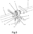
- each one of the rotation transmission modules (5) has a central core (9) arranged with a ball and socket joint set, from which trunnions (10) protrude from the sides, on which the rotation axes (3) of the solar panels (2) of the photovoltaic modules (1) adjacent to the rotation transmission module (5) are moored, by means of fitting and fastening with screws (11), as can be seen in Figure 2 , such that the rotation axes (3) joined to each rotation transmission module (5) are longitudinally associated in the corresponding row of photovoltaic modules (1) and, furthermore, in a solidary rotation assembly.
- At least one rotation transmission module (5) of each row of photovoltaic modules (1) incorporates a spindle and crown transverse transmission (12), which meshes with a central core (9) and, at least, at one of the ends it protrudes with a coupling rod (13); so that in one of said rotation transmission modules (5) the rotation drive motor (4) is arranged on one side and on the other side the universal joint (8) of one end of the transmission bar (7) is moored, while the universal joint (8) at the other end of said transmission bar (7) is moored on the transverse transmission (12) of the rotation module (5) of the other row of photovoltaic modules (1).
- a tilting rotation of all the solar panels (2) is achieved to orient them towards the sun, since through the transverse transmission (12) to which the drive motor (4) is coupled, the rotation of the central core (9) of the corresponding rotation transmission module (5) is driven and through the associated rotation transmission modules (5) the movement is transmitted to all the rotation axes (3) of the photovoltaic modules (1) of the same row, while through the transmission bar (7) the rotation movement is transmitted from one row of photovoltaic modules (1) to another row, thus rotating all the solar panels (2) of the tracker at the same time.
- drive motors (4) can be arranged in connection with two or more rotation transmission modules (5) and, between the rows of photovoltaic modules (1), two or more transmission bars (7) can in turn be arranged, without altering the functional concept of the solar tracker.
- the drive motor (4) is arranged to be assembled on the coupling rod (13) which comes out on one side from the transverse transmission (12) on which the drive is applied, while the transmission bar (7) between the rows of photovoltaic modules (1) is moored on the coupling rod (13) that comes out on the other side of the same transverse transmission (12), whereby the drive motor (4) is longitudinally aligned with the transverse transmission (12) for applying the drive and with the universal joint (8) closest to the assembly of the transmission bar (7) between the rows of photovoltaic modules (1), thus obtaining a practically direct transmission from the drive motor (4), both to the rotation axes (3) of the photovoltaic modules (1) in the same row, and to the aforementioned transmission bar (7) between the rows of modules (1), which favours the effective harnessing of the drive force.
- the assembly of the rotation transmission modules (5) is established in support, by means of conformations (14) by way of legs had by the casing of said rotation transmission modules (5), these conformations (14) by way of legs being supported on trays (15), with respect to which a mooring fastening is established with corresponding screws (11), as can be seen from Figures 3 and 4 .
- the conformations (14) by way of legs have elongated holes (16), which enable the position of the assembly on the trays (15) to be adjusted, to place each rotation transmission module (5) accurately as appropriate in the constructive formation of the solar tracker.
- the trays (15), on which the rotation transmission modules (5) are supported and moored, are joined to brackets (17) with a U-shaped cross-section, which are in turn fastened by mooring by means of screws (11), on the sides of the corresponding support pillars (6), said brackets (17) for fastening the trays (15) having holes (18) for this purpose, which enable the fastening to be established at different height positions on the support pillars (6).
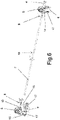
- the universal joints (8) by means of which the fastenings are established are arranged according to a telescopic coupling with respect to the bar (7), whereas the bar (7) itself is envisaged longitudinally made up of independent sections that are joined together by means of a coupling (19) which in turn establishes a telescopic joint, as shown in Figure 6 , whereby the transmission between the rows of the photovoltaic modules (1) can be adjusted in length to adapt the solar tracker assembly as required by the assembly of the installation in each case.
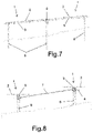
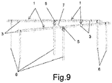
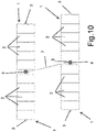
- a solar tracker made up of rows of photovoltaic modules (1) carrying solar panels (2) and provided with a constructive formation according to the aforementioned features can be installed without limitations on terrain of any orography, since it enables the absorption of deviations in height in the longitudinal direction of the rows of photovoltaic modules (1), as shown in Figure 7 , as well as deviations in height in the transverse direction of the arrangement of the rows of said modules (1), as shown in Figure 8 , as deviations of the relative positioning between the rows of photovoltaic modules (1), as shown in Figures 9 and 10 .
- This has a very favourable impact on the installation costs of the solar trackers, since there are no structural adaptations to be made based on the orographic shape of each installation terrain.
Landscapes
- Life Sciences & Earth Sciences (AREA)
- Sustainable Development (AREA)
- Engineering & Computer Science (AREA)
- Physics & Mathematics (AREA)
- Sustainable Energy (AREA)
- Thermal Sciences (AREA)
- Chemical & Material Sciences (AREA)
- Combustion & Propulsion (AREA)
- Mechanical Engineering (AREA)
- General Engineering & Computer Science (AREA)
- Photovoltaic Devices (AREA)
Applications Claiming Priority (1)
| Application Number | Priority Date | Filing Date | Title |
|---|---|---|---|
| ES202130703U ES1271451Y (es) | 2021-04-07 | 2021-04-07 | Seguidor solar con paneles solares orientables dispuestos en filas |
Publications (1)
| Publication Number | Publication Date |
|---|---|
| EP4072008A1 true EP4072008A1 (de) | 2022-10-12 |
Family
ID=76478867
Family Applications (1)
| Application Number | Title | Priority Date | Filing Date |
|---|---|---|---|
| EP22382249.5A Pending EP4072008A1 (de) | 2021-04-07 | 2022-03-16 | Solartracker mit in reihen angeordneten orientierbaren solarpaneelen |
Country Status (4)
| Country | Link |
|---|---|
| US (1) | US11764724B2 (de) |
| EP (1) | EP4072008A1 (de) |
| CN (1) | CN218633808U (de) |
| ES (1) | ES1271451Y (de) |
Cited By (1)
| Publication number | Priority date | Publication date | Assignee | Title |
|---|---|---|---|---|
| CN115892373A (zh) * | 2022-11-14 | 2023-04-04 | 广州大学 | 一种利用太阳能的海洋缓冲装置 |
Families Citing this family (9)
| Publication number | Priority date | Publication date | Assignee | Title |
|---|---|---|---|---|
| US11855581B2 (en) * | 2017-07-18 | 2023-12-26 | Polar Racking Inc. | Solar panel support and drive system |
| USD956538S1 (en) * | 2020-05-08 | 2022-07-05 | Array Technologies, Inc. | Mounting hardware |
| USD956537S1 (en) | 2020-05-08 | 2022-07-05 | Array Technologies, Inc. | Mounting hardware |
| CN115617081A (zh) * | 2021-07-14 | 2023-01-17 | 天合光能股份有限公司 | 一种跟踪方法、装置、电子设备以及存储介质 |
| CN217590716U (zh) | 2022-05-20 | 2022-10-14 | 江苏中信博新能源科技股份有限公司 | 同步驱动装置及光伏跟踪支架系统 |
| IT202200016062A1 (it) | 2022-07-28 | 2024-01-28 | Soltigua S R L | Riduttore di velocita', impianto per produrre energia elettrica provvisto di tale riduttore di velocita' e procedimento per installare tale impianto. |
| ES1296655Y (es) * | 2022-11-11 | 2023-04-18 | Trina Solar S L U | Sistema de conexion de barra de transmision de seguidores solares |
| EP4695900A1 (de) | 2023-04-11 | 2026-02-18 | Array Tech, Inc. | Ausrichtungsklammer |
| US20250067390A1 (en) * | 2023-08-21 | 2025-02-27 | Array Tech, Inc. | Mounting brackets |
Citations (4)
| Publication number | Priority date | Publication date | Assignee | Title |
|---|---|---|---|---|
| US8459249B2 (en) | 2007-06-15 | 2013-06-11 | Ronald P. Corio | Single axis solar tracking system |
| CN205725606U (zh) | 2016-04-29 | 2016-11-23 | 广东保威新能源有限公司 | 一种联动式太阳能跟踪器 |
| US10190801B1 (en) * | 2017-10-17 | 2019-01-29 | King Saud University | Solar heating apparatus |
| CN110620548A (zh) * | 2019-10-21 | 2019-12-27 | 苏州爱康金属科技有限公司 | 多回转驱动联动平单轴追日系统 |
-
2021
- 2021-04-07 ES ES202130703U patent/ES1271451Y/es active Active
-
2022
- 2022-03-09 US US17/690,575 patent/US11764724B2/en active Active
- 2022-03-16 EP EP22382249.5A patent/EP4072008A1/de active Pending
- 2022-04-07 CN CN202220788758.6U patent/CN218633808U/zh active Active
Patent Citations (4)
| Publication number | Priority date | Publication date | Assignee | Title |
|---|---|---|---|---|
| US8459249B2 (en) | 2007-06-15 | 2013-06-11 | Ronald P. Corio | Single axis solar tracking system |
| CN205725606U (zh) | 2016-04-29 | 2016-11-23 | 广东保威新能源有限公司 | 一种联动式太阳能跟踪器 |
| US10190801B1 (en) * | 2017-10-17 | 2019-01-29 | King Saud University | Solar heating apparatus |
| CN110620548A (zh) * | 2019-10-21 | 2019-12-27 | 苏州爱康金属科技有限公司 | 多回转驱动联动平单轴追日系统 |
Cited By (1)
| Publication number | Priority date | Publication date | Assignee | Title |
|---|---|---|---|---|
| CN115892373A (zh) * | 2022-11-14 | 2023-04-04 | 广州大学 | 一种利用太阳能的海洋缓冲装置 |
Also Published As
| Publication number | Publication date |
|---|---|
| ES1271451Y (es) | 2021-10-06 |
| CN218633808U (zh) | 2023-03-14 |
| US11764724B2 (en) | 2023-09-19 |
| ES1271451U (es) | 2021-06-23 |
| US20220329200A1 (en) | 2022-10-13 |
Similar Documents
| Publication | Publication Date | Title |
|---|---|---|
| US11764724B2 (en) | Solar tracker with orientable solar panels arranged in rows | |
| KR100772043B1 (ko) | 추적식 태양광 발전기 | |
| US8203110B2 (en) | Dual axle solar tracker | |
| KR101403129B1 (ko) | 태양광 추종이 가능한 태양광 발전 장치 | |
| US12158001B2 (en) | Truss foundation adapters for single-axis trackers | |
| US20140054433A1 (en) | Alignment and/or tracking device for solar collectors | |
| CA2925905A1 (en) | Solar photovoltaic single axis tracker | |
| KR20200076914A (ko) | 키트화 된 3축형 태양추적 구조물 | |
| CN114815910B (zh) | 翘板式桥架结构及采用该桥架结构的平单轴光伏发电装置 | |
| CN210780650U (zh) | 一种含动态三角形跟踪支撑结构的光伏跟踪支架及其系统 | |
| CN105553398A (zh) | 一种可调节角度的太阳能支架 | |
| KR100937859B1 (ko) | 1축식 태양광 추적 장치 | |
| CN109995315B (zh) | 太阳能光伏跟踪系统 | |
| CN210780651U (zh) | 一种含椭球形自适应轴承的跟踪支撑结构的光伏跟踪支架及其系统 | |
| AU2017203521B2 (en) | Solar tracking system | |
| CN202904379U (zh) | 太阳光斜单轴跟踪装置 | |
| CN206743164U (zh) | 光伏支架及光伏太阳能系统 | |
| KR101173672B1 (ko) | 태양광 발전용 추적 장치 | |
| CN113037198A (zh) | 一种双排联动跟踪系统 | |
| JP2001007374A (ja) | ソーラーユニットの追尾装置 | |
| CN110036563A (zh) | 太阳能电池板跟踪系统 | |
| JP6579512B2 (ja) | 基礎杭とユニットとの接合構造およびそれを使用したユニット工法 | |
| US20240162852A1 (en) | Connection system of a transmission rod for solar trackers | |
| KR102022612B1 (ko) | 조립식 온실 및 이의 시공방법 | |
| KR102589519B1 (ko) | 거더 및 지지폴 일체 십자지주형 태양광패널 지지장치 및 이를 이용한 태양광 발전 시스템 |
Legal Events
| Date | Code | Title | Description |
|---|---|---|---|
| PUAI | Public reference made under article 153(3) epc to a published international application that has entered the european phase |
Free format text: ORIGINAL CODE: 0009012 |
|
| STAA | Information on the status of an ep patent application or granted ep patent |
Free format text: STATUS: THE APPLICATION HAS BEEN PUBLISHED |
|
| AK | Designated contracting states |
Kind code of ref document: A1 Designated state(s): AL AT BE BG CH CY CZ DE DK EE ES FI FR GB GR HR HU IE IS IT LI LT LU LV MC MK MT NL NO PL PT RO RS SE SI SK SM TR |
|
| STAA | Information on the status of an ep patent application or granted ep patent |
Free format text: STATUS: REQUEST FOR EXAMINATION WAS MADE |
|
| 17P | Request for examination filed |
Effective date: 20230331 |
|
| RBV | Designated contracting states (corrected) |
Designated state(s): AL AT BE BG CH CY CZ DE DK EE ES FI FR GB GR HR HU IE IS IT LI LT LU LV MC MK MT NL NO PL PT RO RS SE SI SK SM TR |
|
| P01 | Opt-out of the competence of the unified patent court (upc) registered |
Effective date: 20230517 |
|
| RAP3 | Party data changed (applicant data changed or rights of an application transferred) |
Owner name: TRINA SOLAR SPAIN, S.L.U. |
|
| TPAC | Observations filed by third parties |
Free format text: ORIGINAL CODE: EPIDOSNTIPA |