EP4151561A1 - Werkzeug zum sichern und umdrehen zur montage von fotovoltaischen sonnenfolgerabschnitten, system und zugehöriges montageverfahren - Google Patents
Werkzeug zum sichern und umdrehen zur montage von fotovoltaischen sonnenfolgerabschnitten, system und zugehöriges montageverfahren Download PDFInfo
- Publication number
- EP4151561A1 EP4151561A1 EP20740059.9A EP20740059A EP4151561A1 EP 4151561 A1 EP4151561 A1 EP 4151561A1 EP 20740059 A EP20740059 A EP 20740059A EP 4151561 A1 EP4151561 A1 EP 4151561A1
- Authority
- EP
- European Patent Office
- Prior art keywords
- fastening
- rotating tool
- mounting sections
- photovoltaic solar
- tracker
- Prior art date
- Legal status (The legal status is an assumption and is not a legal conclusion. Google has not performed a legal analysis and makes no representation as to the accuracy of the status listed.)
- Pending
Links
Images

Classifications
-
- B—PERFORMING OPERATIONS; TRANSPORTING
- B65—CONVEYING; PACKING; STORING; HANDLING THIN OR FILAMENTARY MATERIAL
- B65G—TRANSPORT OR STORAGE DEVICES, e.g. CONVEYORS FOR LOADING OR TIPPING, SHOP CONVEYOR SYSTEMS OR PNEUMATIC TUBE CONVEYORS
- B65G49/00—Conveying systems characterised by their application for specified purposes not otherwise provided for
- B65G49/05—Conveying systems characterised by their application for specified purposes not otherwise provided for for fragile or damageable materials or articles
- B65G49/06—Conveying systems characterised by their application for specified purposes not otherwise provided for for fragile or damageable materials or articles for fragile sheets, e.g. glass
- B65G49/068—Stacking or destacking devices; Means for preventing damage to stacked sheets, e.g. spaces
-
- B—PERFORMING OPERATIONS; TRANSPORTING
- B65—CONVEYING; PACKING; STORING; HANDLING THIN OR FILAMENTARY MATERIAL
- B65G—TRANSPORT OR STORAGE DEVICES, e.g. CONVEYORS FOR LOADING OR TIPPING, SHOP CONVEYOR SYSTEMS OR PNEUMATIC TUBE CONVEYORS
- B65G1/00—Storing articles, individually or in orderly arrangement, in warehouses or magazines
- B65G1/02—Storage devices
- B65G1/14—Stack holders or separators
-
- B—PERFORMING OPERATIONS; TRANSPORTING
- B65—CONVEYING; PACKING; STORING; HANDLING THIN OR FILAMENTARY MATERIAL
- B65G—TRANSPORT OR STORAGE DEVICES, e.g. CONVEYORS FOR LOADING OR TIPPING, SHOP CONVEYOR SYSTEMS OR PNEUMATIC TUBE CONVEYORS
- B65G49/00—Conveying systems characterised by their application for specified purposes not otherwise provided for
- B65G49/05—Conveying systems characterised by their application for specified purposes not otherwise provided for for fragile or damageable materials or articles
- B65G49/06—Conveying systems characterised by their application for specified purposes not otherwise provided for for fragile or damageable materials or articles for fragile sheets, e.g. glass
- B65G49/061—Lifting, gripping, or carrying means, for one or more sheets forming independent means of transport, e.g. suction cups, transport frames
-
- B—PERFORMING OPERATIONS; TRANSPORTING
- B65—CONVEYING; PACKING; STORING; HANDLING THIN OR FILAMENTARY MATERIAL
- B65G—TRANSPORT OR STORAGE DEVICES, e.g. CONVEYORS FOR LOADING OR TIPPING, SHOP CONVEYOR SYSTEMS OR PNEUMATIC TUBE CONVEYORS
- B65G49/00—Conveying systems characterised by their application for specified purposes not otherwise provided for
- B65G49/05—Conveying systems characterised by their application for specified purposes not otherwise provided for for fragile or damageable materials or articles
- B65G49/06—Conveying systems characterised by their application for specified purposes not otherwise provided for for fragile or damageable materials or articles for fragile sheets, e.g. glass
- B65G49/067—Sheet handling, means, e.g. manipulators, devices for turning or tilting sheet glass
-
- B—PERFORMING OPERATIONS; TRANSPORTING
- B65—CONVEYING; PACKING; STORING; HANDLING THIN OR FILAMENTARY MATERIAL
- B65G—TRANSPORT OR STORAGE DEVICES, e.g. CONVEYORS FOR LOADING OR TIPPING, SHOP CONVEYOR SYSTEMS OR PNEUMATIC TUBE CONVEYORS
- B65G57/00—Stacking of articles
- B65G57/005—Stacking of articles by using insertions or spacers between the stacked layers
-
- B—PERFORMING OPERATIONS; TRANSPORTING
- B66—HOISTING; LIFTING; HAULING
- B66C—CRANES; LOAD-ENGAGING ELEMENTS OR DEVICES FOR CRANES, CAPSTANS, WINCHES, OR TACKLES
- B66C1/00—Load-engaging elements or devices attached to lifting or lowering gear of cranes or adapted for connection therewith for transmitting lifting forces to articles or groups of articles
- B66C1/10—Load-engaging elements or devices attached to lifting or lowering gear of cranes or adapted for connection therewith for transmitting lifting forces to articles or groups of articles by mechanical means
-
- B—PERFORMING OPERATIONS; TRANSPORTING
- B66—HOISTING; LIFTING; HAULING
- B66C—CRANES; LOAD-ENGAGING ELEMENTS OR DEVICES FOR CRANES, CAPSTANS, WINCHES, OR TACKLES
- B66C23/00—Cranes comprising essentially a beam, boom, or triangular structure acting as a cantilever and mounted for translatory of swinging movements in vertical or horizontal planes or a combination of such movements, e.g. jib-cranes, derricks, tower cranes
- B66C23/18—Cranes comprising essentially a beam, boom, or triangular structure acting as a cantilever and mounted for translatory of swinging movements in vertical or horizontal planes or a combination of such movements, e.g. jib-cranes, derricks, tower cranes specially adapted for use in particular purposes
- B66C23/36—Cranes comprising essentially a beam, boom, or triangular structure acting as a cantilever and mounted for translatory of swinging movements in vertical or horizontal planes or a combination of such movements, e.g. jib-cranes, derricks, tower cranes specially adapted for use in particular purposes mounted on road or rail vehicles; Manually-movable jib-cranes for use in workshops; Floating cranes
- B66C23/44—Jib-cranes adapted for attachment to standard vehicles, e.g. agricultural tractors
-
- F—MECHANICAL ENGINEERING; LIGHTING; HEATING; WEAPONS; BLASTING
- F24—HEATING; RANGES; VENTILATING
- F24S—SOLAR HEAT COLLECTORS; SOLAR HEAT SYSTEMS
- F24S25/00—Arrangement of stationary mountings or supports for solar heat collector modules
- F24S25/60—Fixation means, e.g. fasteners, specially adapted for supporting solar heat collector modules
- F24S25/63—Fixation means, e.g. fasteners, specially adapted for supporting solar heat collector modules for fixing modules or their peripheral frames to supporting elements
-
- F—MECHANICAL ENGINEERING; LIGHTING; HEATING; WEAPONS; BLASTING
- F24—HEATING; RANGES; VENTILATING
- F24S—SOLAR HEAT COLLECTORS; SOLAR HEAT SYSTEMS
- F24S25/00—Arrangement of stationary mountings or supports for solar heat collector modules
- F24S2025/01—Special support components; Methods of use
- F24S2025/013—Stackable support elements
-
- F—MECHANICAL ENGINEERING; LIGHTING; HEATING; WEAPONS; BLASTING
- F24—HEATING; RANGES; VENTILATING
- F24S—SOLAR HEAT COLLECTORS; SOLAR HEAT SYSTEMS
- F24S80/00—Details, accessories or component parts of solar heat collectors not provided for in groups F24S10/00-F24S70/00
-
- Y—GENERAL TAGGING OF NEW TECHNOLOGICAL DEVELOPMENTS; GENERAL TAGGING OF CROSS-SECTIONAL TECHNOLOGIES SPANNING OVER SEVERAL SECTIONS OF THE IPC; TECHNICAL SUBJECTS COVERED BY FORMER USPC CROSS-REFERENCE ART COLLECTIONS [XRACs] AND DIGESTS
- Y02—TECHNOLOGIES OR APPLICATIONS FOR MITIGATION OR ADAPTATION AGAINST CLIMATE CHANGE
- Y02E—REDUCTION OF GREENHOUSE GAS [GHG] EMISSIONS, RELATED TO ENERGY GENERATION, TRANSMISSION OR DISTRIBUTION
- Y02E10/00—Energy generation through renewable energy sources
- Y02E10/40—Solar thermal energy, e.g. solar towers
- Y02E10/47—Mountings or tracking
-
- Y—GENERAL TAGGING OF NEW TECHNOLOGICAL DEVELOPMENTS; GENERAL TAGGING OF CROSS-SECTIONAL TECHNOLOGIES SPANNING OVER SEVERAL SECTIONS OF THE IPC; TECHNICAL SUBJECTS COVERED BY FORMER USPC CROSS-REFERENCE ART COLLECTIONS [XRACs] AND DIGESTS
- Y02—TECHNOLOGIES OR APPLICATIONS FOR MITIGATION OR ADAPTATION AGAINST CLIMATE CHANGE
- Y02E—REDUCTION OF GREENHOUSE GAS [GHG] EMISSIONS, RELATED TO ENERGY GENERATION, TRANSMISSION OR DISTRIBUTION
- Y02E10/00—Energy generation through renewable energy sources
- Y02E10/50—Photovoltaic [PV] energy
Definitions
- the present invention is included in the technical field of mounting photovoltaic solar trackers in a pre-assembled manner and specifically in the field of tools for mounting, rotating and loading the sections of pre-assembled solar trackers on autonomous transportation means in order to transport them to the specific location of said solar trackers in the field. It also includes the mounting system.
- the object of the present invention is a fastening and rotating tool for mounting sections of photovoltaic solar trackers which enables the tasks of pre-assembly, transportation and installation of the solar tracker section, thereby reducing the mounting times for each of the operations.
- the invention also relates to an associated system and method that makes use of the fastening and rotating tool for mounting pre-assembled sections of photovoltaic solar trackers, as well as the means associated with the mounting system.
- Photovoltaic solar trackers are formed by a set of photovoltaic panels which are coupled to a structure that has the capability to be oriented in order to track the trajectory of the sun at all times and capture the maximum amount of solar radiation possible at all times of the day.
- Document JP2016204966A which relates to a solar power plant construction method able to guarantee safety for workers in a short construction period and to be installed at a low cost, and a container for transporting a tracker used in the method, is known in the state of the art. It comprises a step of manufacturing the panel by means of the arrangement and fastening the solar modules transported to an assembly plant in a support frame; a transportation step in which solar panels are accumulated in a specific container and the container is loaded on a container truck in order to transport it to a power generation site; and a solar panel installation process, taking into account the position of the container truck with respect to the support where the solar panel will be installed.
- Document US2014076383A1 is also known, and describes an apparatus for stacking a plurality of solar module arrays, each having a plurality of solar panels.
- the apparatus includes a lower portion disposed on top of a first solar panel support channel corresponding to a first solar module array, and an upper portion for supporting a second solar panel support channel corresponding to a second solar module array, wherein the second solar module array is stacked above the first solar module array.
- the fastening and rotating tool for mounting pre-assembled sections of photovoltaic solar trackers of the present invention facilitates the pre-assembly, transportation and installation of the solar tracker section, reducing the mounting times of each operation, thereby improving the features of mounting systems used in the field known in the state of the art.
- the present invention relates to a fastening and rotating tool for mounting pre-assembled sections of solar trackers which allows solar tracker sections to be mounted, rotated and loaded on autonomous transportation means in order to transport them to the specific location of said solar trackers in the field.
- the fastening and rotating tool comprises a frame which in turn comprises:
- the fastening and rotating tool further comprises a central slit arranged in the frame and configured to couple the fastening and rotating tool to a central beam of the solar tracker section.
- the central slit is arranged equidistant to the at least two hooks.
- the central slit is arranged in the central portion of the fastening and rotating tool.
- the central slit defines a longitudinal direction corresponding to the longitudinal direction of the central beam. In this manner, the tool can couple to any one of the solar tracker sections.
- the coupling is preferably carried out by means of a screw joint.
- the mortises further comprise first holes which in turn define an axis of rotation and are configured to carry out the rotation of the fastening and rotating tool, as well as the tracker section joined to the same.
- the first holes are configured to carry out the rotation of the fastening and rotating tool 180°.
- the axis of rotation defined by the first holes of the mortises is parallel to the longitudinal direction of the central slit.
- the mortises further comprise a second hole configured to carry out the locking of the fastening and rotating tool during the transportation.
- the second hole is perpendicular to a transverse direction which is perpendicular to the longitudinal direction of the central slit.
- each of the second holes of each one of the fastening and rotating tools are arranged in the transverse direction during the transportation of at least the first solar tracker section and the second solar tracker section arranged above the first solar tracker section.
- the associated mounting system of the present invention comprises at least one fastening tool for each one of the solar tracker sections, preferably at least two fastening and rotating tools for each solar tracker section, arranged along the longitudinal direction of the central beam.
- the system further comprises pre-assembly means configured to carry out the pre-assembly of the fastening and rotating tool or tools to the central beam of the solar tracker section and consequently to said solar tracker section.
- the system further comprises support means configured to support the tracker section along with the fastening and rotating tool or tools when the rotation of the tracker section along with the fastening and rotating tool or tools is carried out.
- the system further comprises rotating means configured to carry out the rotation of the tracker section by means of the rotating tool or tools from the pre-assembly means to the support means.
- the system further comprises autonomous transportation means configured to transport the tracker sections along with the rotating tools to the definitive location thereof in the field.
- the rotating means are also configured to carry out the movement of the tracker section by means of the rotating tool or tools from the support means to the autonomous transportation means.
- the system further comprises locking means configured to carry out the locking of at least two tracker sections on the autonomous transportation means, the first solar tracker section and the second solar tracker section arranged above the first solar tracker section during the transportation of the same by means of the autonomous transportation means.
- the locking means comprise at least one pin arranged inside the second hole of each of one of the mortises of each fastening and rotating tool.
- the system further comprises means for installing the pre-assembled solar tracker sections on supports of the solar tracker in the field.
- the invention also relates to an associated mounting method carried out with at least one fastening tool for each one of the solar tracker sections, preferably with at least two fastening and rotating tools for each one of the solar tracker segments, arranged along the longitudinal direction of the central beam.
- the method further comprises a pre-assembly step wherein the pre-assembly of the fastening and rotating tool or tools to the central beam of the solar tracker section has been carried out and, thus, to said solar tracker section.
- the method further comprises a rotating step wherein the rotation of the tracker section is carried out by means of the rotating tool or tools after the pre-assembly step.
- the method further comprises a support step wherein the support of the tracker section along with the fastening and rotating tool or tools is carried out after the step of rotating the tracker section along with the fastening and rotating tool or tools.
- the method further comprises a step of moving the tracker section along with the rotating tool or tools after the support step.
- the method further comprises an autonomous transportation step wherein the transportation of the tracker sections along with the rotating tools to the definitive location thereof in the field is carried out.
- the method further comprises a locking step wherein the locking of at least two tracker sections is carried out, the first solar tracker section and the second solar tracker section arranged above the first solar tracker section during the transportation of the same.
- the locking step is carried out by arranging at least one pin arranged inside the second hole of each one of the mortises of each fastening and rotating tool.
- the method further comprises a step of installing the solar tracker sections on supports of the solar tracker in the field.
- the method further comprises a step of removing the fastening and rotating tool or tools.
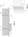
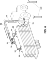
- the fastening and rotating tool (200) comprises a frame (100) which in turn comprises at least two hooks (1) configured to be fastened by preferably automatic installation means (50, 51, 52) of the solar tracker sections (101, 102) and mortises (2) arranged opposite from the hooks (1) configured to receive the at least two hooks (1) of a tool arranged below, such that the hooks (1) and the mortises (2) further define the separation between a first solar tracker section (101) and a second solar tracker section (101) arranged above the first solar tracker section (101) during the transportation of the same.
- the fastening and rotating tool further comprises a central slit (3) arranged in the frame (100) and configured to couple the fastening and rotating tool to a central beam (150) of the solar tracker section (101, 102), wherein the central slit (3) is preferably square-shaped.
- the central slit (3) is arranged equidistant to the at least two hooks (1) in a central portion of the fastening and rotating tool. Said central slit (3) defines a longitudinal direction corresponding to the longitudinal direction of the central beam (150).
- the mortises (2) further comprise first holes (4) which in turn define an axis of rotation (5) and are configured to carry out the rotation of the fastening and rotating tool and, therefore, the tracker section (101, 102) joined to the same 180°, wherein the axis of rotation (5) defined by the first holes (4) of the mortises (2) is parallel to the longitudinal direction of the central slit (150).
- the mortises (2) further comprise a second hole (6) configured to carry out the locking of the fastening and rotating tool during transportation, wherein the second hole (6) is perpendicular to a transverse direction that is perpendicular to the longitudinal direction of the central slit (150).
- the frame of the fastening and rotating tool comprises two flanges (7) joined by reinforcing ribs (8), wherein the hooks are arranged between the flanges (7), projecting above the same (7) and/or the first holes (4) are arranged on ends (9) of the flanges (7) and/or wherein the second holes (6) are arranged on reinforcing ribs (8) arranged on the ends of the frame.
- the associated mounting system of the present invention in this embodiment comprises two fastening tools for each one of the solar tracker sections (101 102), preferably at least two fastening and rotating tools for each solar tracker section (102), arranged along the longitudinal direction of the central beam (150).
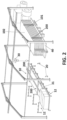
- the system further comprises pre-assembly means (10, 11, 12) configured to carry out the pre-assembly of the fastening and rotating tool or tools to the central beam of the solar tracker section and, thus, to said solar tracker section, wherein said pre-assembly means (10, 11, 12) comprise a pre-assembly table (10), a power supply (11) for central beams (150) and a power supply (12) for photovoltaic modules of the solar tracker sections (101, 102).
- pre-assembly means (10, 11, 12) comprise a pre-assembly table (10), a power supply (11) for central beams (150) and a power supply (12) for photovoltaic modules of the solar tracker sections (101, 102).
- the system further comprises support means (20) configured to support the tracker section (101, 102) along with the fastening and rotating tool or tools when the rotation of the tracker section (101, 102) along with the fastening and rotating tool or tools is carried out.
- the support means comprise rotating legs (20) arranged adjacent to the pre-assembly means (10, 11, 12).
- the system further comprises rotating means (30, 31) configured to carry out the rotation of the tracker section by means of the rotating tool or tools from the pre-assembly means (10, 11, 12) to the support means (20).
- the rotating means comprise a block and tackle (30) and a bar (31) arranged on the inside of the first holes (4) which define the axis of rotation (5), such that the block and tackle (30) carries out the rotation of the solar tracker section (101, 102) by means of the rotating tool or tools due to the fact that the bar (31) is anchored in a rotational manner to the pre-assembly means (10, 11, 12).
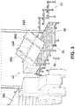
- the system further comprises autonomous transportation means (40), preferably an autonomous vehicle, configured to transport the tracker sections (101, 102) along with the rotating tools to the definitive location thereof in the field.
- autonomous transportation means preferably an autonomous vehicle, configured to transport the tracker sections (101, 102) along with the rotating tools to the definitive location thereof in the field.
- the block and tackle (30) of the rotating means (30, 31) are also configured to carry out the movement of the tracker section (101, 102) along with the rotating tool or tools from the support means to the autonomous transportation means (40).
- the system further comprises locking means (60) configured to carry out the locking of at least two tracker sections on the autonomous transportation means (40), the first solar tracker section (101) and the second solar tracker section (102) arranged above the first solar tracker section (101) during the transportation of the same by means of the autonomous transportation means (40).
- the locking means comprise at least one pin (60) arranged inside the second hole (6) of each one of the mortises (2) of each fastening and rotating tool.
- the system further comprises installation means (50, 51, 52) for the solar tracker sections (101, 102) on supports (160) of the solar tracker in the field, which are preferably automatic by means of position sensors and computer vision cameras.
- the installation means comprise a set of telescopic arms (50), slewing rings (51) and gripping means (52) which enable the fastening of the hooks (1) of the fastening and rotating tools and the installation of the solar tracker section (101, 102) on the supports (160) of the solar tracker to be carried out.
- the installation means (50, 51, 52) further comprise a set of cameras (not shown) which carry out the detection of a set of targets (not shown) arranged on the supports (160) of the solar tracker wherein the solar tracker section will be placed.
Landscapes
- Engineering & Computer Science (AREA)
- Mechanical Engineering (AREA)
- Life Sciences & Earth Sciences (AREA)
- Agronomy & Crop Science (AREA)
- Physics & Mathematics (AREA)
- Sustainable Development (AREA)
- Sustainable Energy (AREA)
- Thermal Sciences (AREA)
- Chemical & Material Sciences (AREA)
- Combustion & Propulsion (AREA)
- General Engineering & Computer Science (AREA)
- Photovoltaic Devices (AREA)
- Load-Engaging Elements For Cranes (AREA)
Applications Claiming Priority (1)
| Application Number | Priority Date | Filing Date | Title |
|---|---|---|---|
| PCT/ES2020/070303 WO2021229110A1 (es) | 2020-05-12 | 2020-05-12 | Útil de sujeción y volteo para el montaje de tramos de seguidores solares fotovoltaicos, sistema y procedimiento de montaje asociado |
Publications (1)
| Publication Number | Publication Date |
|---|---|
| EP4151561A1 true EP4151561A1 (de) | 2023-03-22 |
Family
ID=71608017
Family Applications (1)
| Application Number | Title | Priority Date | Filing Date |
|---|---|---|---|
| EP20740059.9A Pending EP4151561A1 (de) | 2020-05-12 | 2020-05-12 | Werkzeug zum sichern und umdrehen zur montage von fotovoltaischen sonnenfolgerabschnitten, system und zugehöriges montageverfahren |
Country Status (4)
| Country | Link |
|---|---|
| US (1) | US20230174324A1 (de) |
| EP (1) | EP4151561A1 (de) |
| AU (1) | AU2020447274A1 (de) |
| WO (1) | WO2021229110A1 (de) |
Families Citing this family (3)
| Publication number | Priority date | Publication date | Assignee | Title |
|---|---|---|---|---|
| EP4121253A4 (de) | 2020-03-20 | 2024-04-17 | Rosendin Electric, Inc. | Autonomes bodenfahrzeug zur solarmodulinstallation |
| CN118025812B (zh) * | 2024-04-15 | 2024-07-05 | 湖南福力科技有限公司 | 一种光伏组件的安装输料设备 |
| US20250340381A1 (en) * | 2024-05-02 | 2025-11-06 | Terabase Energy, Inc. | Solar table rack with off-loader |
Family Cites Families (5)
| Publication number | Priority date | Publication date | Assignee | Title |
|---|---|---|---|---|
| JP2003128377A (ja) * | 2001-10-24 | 2003-05-08 | Hmy Ltd | 長尺材用荷台、それを用いた長尺材ハンドリング方法、及び長尺材運搬システム |
| US20140076383A1 (en) * | 2010-05-24 | 2014-03-20 | Chevron U.S.A. Inc. | Solar module array pre-assembly method and apparatus |
| CN102935910A (zh) * | 2012-11-06 | 2013-02-20 | 上海宝松盐城重型机械工程有限公司 | 钢板存放架 |
| JP6231515B2 (ja) | 2015-04-22 | 2017-11-15 | クリーンエナジーファクトリー株式会社 | 太陽光発電プラント施工法 |
| US10469024B2 (en) * | 2016-04-08 | 2019-11-05 | Solarcity Corporation | Pre-assembled nesting photovoltaic module bracket for solar tracker |
-
2020
- 2020-05-12 AU AU2020447274A patent/AU2020447274A1/en active Pending
- 2020-05-12 EP EP20740059.9A patent/EP4151561A1/de active Pending
- 2020-05-12 US US17/925,189 patent/US20230174324A1/en active Pending
- 2020-05-12 WO PCT/ES2020/070303 patent/WO2021229110A1/es not_active Ceased
Also Published As
| Publication number | Publication date |
|---|---|
| WO2021229110A1 (es) | 2021-11-18 |
| AU2020447274A1 (en) | 2022-12-15 |
| US20230174324A1 (en) | 2023-06-08 |
Similar Documents
| Publication | Publication Date | Title |
|---|---|---|
| US20210218363A1 (en) | Pre-assembly plant for photovoltaic solar trackers and pre-assembly method associated with said plant | |
| US20230174324A1 (en) | Tool for securing and turning over for assembling photovoltaic solar tracker sections, system and associated assembly method | |
| US9349893B2 (en) | Photovoltaic module ground mount | |
| US12539801B2 (en) | Solar table mobile transport | |
| US9556626B2 (en) | Self-jacking scaffold for large cylindrical tanks | |
| US10469024B2 (en) | Pre-assembled nesting photovoltaic module bracket for solar tracker | |
| US20110272367A1 (en) | Device for supporting solar modules | |
| US9920748B2 (en) | Method and tool for assembling tower elements | |
| US9714135B2 (en) | Container for solar string transportation | |
| US20140360552A1 (en) | Solar Panel Field Array Support System and Apparatus and Method for Construction Use | |
| CN121443420A (zh) | 具有侧移的太阳能板台移动运输装置 | |
| US20230238912A1 (en) | Centralized solar table assembly | |
| JP6231515B2 (ja) | 太陽光発電プラント施工法 | |
| CN118321907B (zh) | 光伏阵列半成品组装方法 | |
| US9394689B2 (en) | Tiltable beams for flat roof solar sensor structures | |
| US20250150023A1 (en) | Photovoltaic module mounting rails | |
| US8646230B2 (en) | Flat roof support structure | |
| US12375028B2 (en) | System of photovoltaic solar panels | |
| EP3796549A1 (de) | Verfahren zur herstellung einer fotovoltaischen solarstromerzeugungsvorrichtung, einspannvorrichtung zur herstellung einer fotovoltaischen solarstromerzeugungsvorrichtung und einrichtung zur herstellung einer fotovoltaischen solarstromerzeugungsvorrichtung | |
| WO2023079377A1 (en) | Movable system for assembling support frames for arrays of photovoltaic panels and for installing said support frames on a receiving structure | |
| WO2025160314A1 (en) | Solar table mobile transport vehicle with rack | |
| WO2022201206A1 (en) | A universal solar module mounting structure assembly | |
| US20260063333A1 (en) | Systems and methods for automatic solar table landing and securement | |
| US20250233552A1 (en) | Solar module frame couplings | |
| US20260058599A1 (en) | Pin locking rail for solar module frame coupling |
Legal Events
| Date | Code | Title | Description |
|---|---|---|---|
| STAA | Information on the status of an ep patent application or granted ep patent |
Free format text: STATUS: UNKNOWN |
|
| STAA | Information on the status of an ep patent application or granted ep patent |
Free format text: STATUS: THE INTERNATIONAL PUBLICATION HAS BEEN MADE |
|
| PUAI | Public reference made under article 153(3) epc to a published international application that has entered the european phase |
Free format text: ORIGINAL CODE: 0009012 |
|
| STAA | Information on the status of an ep patent application or granted ep patent |
Free format text: STATUS: REQUEST FOR EXAMINATION WAS MADE |
|
| 17P | Request for examination filed |
Effective date: 20221110 |
|
| AK | Designated contracting states |
Kind code of ref document: A1 Designated state(s): AL AT BE BG CH CY CZ DE DK EE ES FI FR GB GR HR HU IE IS IT LI LT LU LV MC MK MT NL NO PL PT RO RS SE SI SK SM TR |
|
| DAV | Request for validation of the european patent (deleted) | ||
| DAX | Request for extension of the european patent (deleted) | ||
| GRAP | Despatch of communication of intention to grant a patent |
Free format text: ORIGINAL CODE: EPIDOSNIGR1 |
|
| STAA | Information on the status of an ep patent application or granted ep patent |
Free format text: STATUS: GRANT OF PATENT IS INTENDED |
|
| INTG | Intention to grant announced |
Effective date: 20251006 |