EP3710840B1 - Stromregulierender wandler - Google Patents
Stromregulierender wandler Download PDFInfo
- Publication number
- EP3710840B1 EP3710840B1 EP18807026.2A EP18807026A EP3710840B1 EP 3710840 B1 EP3710840 B1 EP 3710840B1 EP 18807026 A EP18807026 A EP 18807026A EP 3710840 B1 EP3710840 B1 EP 3710840B1
- Authority
- EP
- European Patent Office
- Prior art keywords
- circuit board
- current
- microprocessor
- power conversion
- conversion system
- Prior art date
- Legal status (The legal status is an assumption and is not a legal conclusion. Google has not performed a legal analysis and makes no representation as to the accuracy of the status listed.)
- Active
Links
- 239000004020 conductor Substances 0.000 claims description 42
- 238000006243 chemical reaction Methods 0.000 claims description 38
- 238000004891 communication Methods 0.000 claims description 10
- 238000005259 measurement Methods 0.000 description 5
- 230000004907 flux Effects 0.000 description 4
- 230000006870 function Effects 0.000 description 4
- 238000012423 maintenance Methods 0.000 description 3
- 239000003989 dielectric material Substances 0.000 description 2
- 230000007257 malfunction Effects 0.000 description 2
- 238000012545 processing Methods 0.000 description 2
- 238000004804 winding Methods 0.000 description 2
- 230000005355 Hall effect Effects 0.000 description 1
- 230000000295 complement effect Effects 0.000 description 1
- 150000001875 compounds Chemical class 0.000 description 1
- 239000012141 concentrate Substances 0.000 description 1
- 230000008878 coupling Effects 0.000 description 1
- 238000010168 coupling process Methods 0.000 description 1
- 238000005859 coupling reaction Methods 0.000 description 1
- 230000001419 dependent effect Effects 0.000 description 1
- 238000001514 detection method Methods 0.000 description 1
- 238000010586 diagram Methods 0.000 description 1
- 230000010354 integration Effects 0.000 description 1
- 239000000696 magnetic material Substances 0.000 description 1
- 238000000034 method Methods 0.000 description 1
- 238000012544 monitoring process Methods 0.000 description 1
- 230000035699 permeability Effects 0.000 description 1
- 238000004382 potting Methods 0.000 description 1
- 238000005070 sampling Methods 0.000 description 1
- 238000009738 saturating Methods 0.000 description 1
- 238000000926 separation method Methods 0.000 description 1
- 230000035939 shock Effects 0.000 description 1
- 229910000679 solder Inorganic materials 0.000 description 1
- 230000003068 static effect Effects 0.000 description 1
- 238000003466 welding Methods 0.000 description 1
Images


Classifications
-
- G—PHYSICS
- G01—MEASURING; TESTING
- G01R—MEASURING ELECTRIC VARIABLES; MEASURING MAGNETIC VARIABLES
- G01R15/00—Details of measuring arrangements of the types provided for in groups G01R17/00 - G01R29/00, G01R33/00 - G01R33/26 or G01R35/00
- G01R15/14—Adaptations providing voltage or current isolation, e.g. for high-voltage or high-current networks
- G01R15/20—Adaptations providing voltage or current isolation, e.g. for high-voltage or high-current networks using galvano-magnetic devices, e.g. Hall-effect devices, i.e. measuring a magnetic field via the interaction between a current and a magnetic field, e.g. magneto resistive or Hall effect devices
- G01R15/207—Constructional details independent of the type of device used
-
- G—PHYSICS
- G01—MEASURING; TESTING
- G01R—MEASURING ELECTRIC VARIABLES; MEASURING MAGNETIC VARIABLES
- G01R19/00—Arrangements for measuring currents or voltages or for indicating presence or sign thereof
- G01R19/25—Arrangements for measuring currents or voltages or for indicating presence or sign thereof using digital measurement techniques
- G01R19/2513—Arrangements for monitoring electric power systems, e.g. power lines or loads; Logging
-
- G—PHYSICS
- G01—MEASURING; TESTING
- G01R—MEASURING ELECTRIC VARIABLES; MEASURING MAGNETIC VARIABLES
- G01R33/00—Arrangements or instruments for measuring magnetic variables
- G01R33/0011—Arrangements or instruments for measuring magnetic variables comprising means, e.g. flux concentrators, flux guides, for guiding or concentrating the magnetic flux, e.g. to the magnetic sensor
-
- H—ELECTRICITY
- H02—GENERATION; CONVERSION OR DISTRIBUTION OF ELECTRIC POWER
- H02P—CONTROL OR REGULATION OF ELECTRIC MOTORS, ELECTRIC GENERATORS OR DYNAMO-ELECTRIC CONVERTERS; CONTROLLING TRANSFORMERS, REACTORS OR CHOKE COILS
- H02P6/00—Arrangements for controlling synchronous motors or other dynamo-electric motors using electronic commutation dependent on the rotor position; Electronic commutators therefor
- H02P6/08—Arrangements for controlling the speed or torque of a single motor
Claims (12)
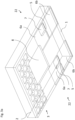
- Stromregulierender Wandler, der eine Leiterplatte (1), einen oder mehrere Stromsensoren (22), mindestens einen Mikroprozessor (8) auf der Leiterplatte und einen Verbinder (3) mit Verbindungsanschlüssen umfasst, die mit der Leiterplatte verbunden sind und dazu ausgestaltet sind, über einen externen Verbinder oder eine zusätzliche Leiterplatte mit einem Leistungsumwandlungssystem (32) und einer Steuereinrichtung (30) einer höheren Ebene außerhalb des Wandlers verbunden zu sein,wobei jeder Stromsensor einen Hauptleiter (6) mit Eingangs- und Ausgangsanschlüssen (6a, 6b), die dazu ausgestaltet sind, mit einer elektrischen Phase des Leistungsumwandlungssystem verbunden zu sein, und einen Magnetfelddetektor (7) umfasst, der dazu ausgestaltet ist, das Magnetfeld, das durch einen Hauptstrom, der in dem Hauptleiter fließt, erzeugt wird, zu messen, wobei jeder Stromsensor mit einer Steuereinrichtung (21) des Mikroprozessors verbunden ist,wobei der Mikroprozessor ferner Folgendes umfasst:eine Kommunikationsschnittstelle (28), die dazu ausgestaltet ist, mit der Steuereinrichtung der höheren Ebene über die Verbindungsanschlüsse des Verbinders zu kommunizieren, undeinen Speicher (50), der einen Konfigurationsdatenspeicher (33) umfasst, der dazu ausgestaltet ist, Informationen zu speichern, die eine Konfiguration des Leistungsumwandlungssystems betreffen,wobei der Mikroprozessor mit einem oder mehreren Steuersignal-Verbindungsanschlüssen des Verbinders verbunden ist, die dazu ausgestaltet sind, mit dem Leistungsumwandlungssystem zu dessen Steuerung basierend auf Sollwert-Stromwerten und dem einen oder den mehreren von den Stromsensoren gemessenen Hauptströmen verbunden zu sein,wobei die Sollwert-Stromwerte von der Steuereinrichtung (30) der höheren Ebene, dem Leistungsumwandlungssystem (32) oder dem Speicher (50) bereitgestellt werden oder von der Steuereinrichtung (21) basierend auf den Informationen, welche die Konfiguration des Leistungsumwandlungssystems betreffen, die in dem Konfigurationsdatenspeicher (33) gespeichert sind, berechnet und bereitgestellt werden, undwobei der Hauptleiter, der Magnetfeldsensor, der Mikroprozessor, die Leiterplatte und der Verbinder direkt zusammen integriert sind, um eine einzige Einheit zu bilden, die mit dem Leistungsumwandlungssystem und einer Steuereinrichtung des Leistungsumwandlungssystems verbindbar ist.
- Stromregulierender Wandler nach dem vorhergehenden Anspruch, wobei der Mikroprozessor (8) ferner eine Analog/Digitalschaltung (25) umfasst und wobei jeder Stromsensor mit der Analog/Digitalschaltung (25) des Mikroprozessors verbunden ist.
- Stromregulierender Wandler nach einem der vorhergehenden Ansprüche, wobei die Verbindungsanschlüsse des Verbinders auf einer ersten Seite (1a) der Leiterplatte bereitgestellt sind und der Magnetfeldsensor und Mikroprozessor auf einer zweiten Seite (1b) der Leiterplatte montiert sind.
- Stromregulierender Wandler nach einem der vorhergehenden Ansprüche, wobei der Mikroprozessor ferner eine Bedingungsüberwachungseinrichtung (34) umfasst, die mit einem Ausgang des einen oder der mehreren Stromsensoren verbunden ist, wobei die Bedingungsüberwachungseinrichtung einen Bedingungsdatenspeicher (35) in dem Speicher (50) des Mikroprozessors umfasst, der dazu ausgestaltet ist, Verlaufsdaten zu speichern, die Informationen von den Stromsensoren betreffen.
- Stromregulierender Wandler nach einem der vorhergehenden Ansprüche, wobei die Kommunikationsschnittstelle dazu ausgestaltet ist, mit der externen Steuereinrichtung der höheren Ebene über eine serielle Verbindung (29) verbunden zu sein.
- Stromregulierender Wandler nach einem der vorhergehenden Ansprüche, wobei eine übergossene Schicht (2) die Magnetfeldsensoren und den Mikroprozessor bedeckt.
- Stromregulierender Wandler nach einem der vorhergehenden Ansprüche, wobei jeder Hauptleiter aus Leiterbahnen auf der Leiterplatte besteht, die Leiterbahn-Kontaktgebiete (6a, 6b) umfassen, die durch einen schmalen Brückenabschnitt (5) zusammengeschaltet sind.
- Stromregulierender Wandler nach einem der vorhergehenden Ansprüche, wobei ein Verbindungslayout der Leiterplatte in einem Land Grid Array (LGA) Package implementiert ist, das die Leiterplatte, Leiterbahnen auf einer ersten Seite (1a) der Leiterplatte, die Masse, Leistungsversorgung und die Kommunikationsschnittstellen-Verbindungsanschlüsse (3) umfassen, und eine übergossene Schicht (2) auf einer zweiten Seite (1b) der Leiterplatte umfasst, welche die Magnetfeldsensoren und den Mikroprozessor bedeckt.
- Stromregulierender Wandler nach einem der Ansprüche 1 bis 7, wobei jeder Stromsensor einen Magnetkern (9) umfasst, der einen mittleren Abschnitt (6c) von jedem Hauptleiter zumindest teilweise umgibt, und wobei die Leiterplatte Schlitze (14) umfasst, die dazu ausgestaltet sind, es Verzweigungen (9b) des Magnetkerns zu erlauben, sich von einer ersten Seite (1a) zur zweiten Seite (1b) durch die Leiterplatte zu erstrecken.
- Stromregulierender Wandler nach einem der vorhergehenden Ansprüche 1 bis 7, der ferner eine Kompensationswicklung (13) umfasst, wobei jeder Stromsensor einen Magnetkern (9) umfasst, der den Hauptleiter umgibt und sich durch einen Kern der Kompensationswicklung (13) erstreckt, wobei ein Luftspalt zwischen einer Verzweigung des Magnetkerns, die sich durch den Kern der Kompensationswicklung hinauf bis zu einer ersten Seite (1a) der Leiterplatte erstreckt, und einer Endverzweigung (9a) des Magnetkerns gebildet ist, die sich über der zweiten Seite (1b) der Leiterplatte erstreckt, wobei der Magnetfelddetektor auf einer zweiten Seite der Leiterplatte montiert ist und in dem Luftspalt positioniert ist.
- Stromregulierender Wandler nach dem vorhergehenden Anspruch, wobei die Verbindungsanschlüsse des Verbinders sich entlang eines Randes (1c) der Leiterplatte erstrecken.
- Stromregulierender Wandler nach einem der beiden direkt vorhergehenden Ansprüche, wobei der Hauptleiter eine Vielzahl von Leiterabschnitten (6') umfasst, die U-förmige Leiterabschnitte bilden, die um die Kompensationswicklung montiert sind.
Applications Claiming Priority (2)
| Application Number | Priority Date | Filing Date | Title |
|---|---|---|---|
| EP17201932 | 2017-11-15 | ||
| PCT/EP2018/081266 WO2019096865A1 (en) | 2017-11-15 | 2018-11-14 | Current controlling transducer |
Publications (3)
| Publication Number | Publication Date |
|---|---|
| EP3710840A1 EP3710840A1 (de) | 2020-09-23 |
| EP3710840B1 true EP3710840B1 (de) | 2023-06-07 |
| EP3710840C0 EP3710840C0 (de) | 2023-06-07 |
Family
ID=60331468
Family Applications (1)
| Application Number | Title | Priority Date | Filing Date |
|---|---|---|---|
| EP18807026.2A Active EP3710840B1 (de) | 2017-11-15 | 2018-11-14 | Stromregulierender wandler |
Country Status (2)
| Country | Link |
|---|---|
| EP (1) | EP3710840B1 (de) |
| WO (1) | WO2019096865A1 (de) |
Family Cites Families (10)
| Publication number | Priority date | Publication date | Assignee | Title |
|---|---|---|---|---|
| US4980794A (en) * | 1987-02-19 | 1990-12-25 | Westinghouse Electric Corp. | Electromagnetic contactor with lightweight wide range current transducer with sintered powdered metal core |
| EP1617228B1 (de) * | 2004-07-16 | 2008-10-22 | Liaisons Electroniques-Mecaniques Lem S.A. | Stromsensor |
| WO2008036110A2 (en) * | 2006-02-03 | 2008-03-27 | Bae Systems Land & Armaments L.P. | Modularized servo control system |
| US9310398B2 (en) * | 2011-11-29 | 2016-04-12 | Infineon Technologies Ag | Current sensor package, arrangement and system |
| EP2660611A1 (de) * | 2012-04-30 | 2013-11-06 | LEM Intellectual Property SA | Elektrisches Stromtransformatormodul |
| US9917545B2 (en) * | 2013-09-20 | 2018-03-13 | Schweitzer Engineering Laboratories, Inc. | Electric motor thermal protection using stator current measurements |
| CN203809329U (zh) * | 2014-04-14 | 2014-09-03 | 江苏多维科技有限公司 | 一种直流风扇控制芯片 |
| EP2942631B1 (de) * | 2014-04-28 | 2024-03-06 | TYCO ELECTRONICS AMP KOREA Co., Ltd. | Hybridstromsensoranordnung |
| JP6544981B2 (ja) * | 2015-04-20 | 2019-07-17 | ローム株式会社 | プリント配線基板 |
| US10063154B2 (en) * | 2016-04-29 | 2018-08-28 | Semiconductor Components Industries, Llc | Current sense detection for synchronous rectification |
-
2018
- 2018-11-14 WO PCT/EP2018/081266 patent/WO2019096865A1/en unknown
- 2018-11-14 EP EP18807026.2A patent/EP3710840B1/de active Active
Also Published As
| Publication number | Publication date |
|---|---|
| WO2019096865A1 (en) | 2019-05-23 |
| EP3710840C0 (de) | 2023-06-07 |
| EP3710840A1 (de) | 2020-09-23 |
Similar Documents
| Publication | Publication Date | Title |
|---|---|---|
| EP3620799B1 (de) | Strommessmodul | |
| JP5702862B2 (ja) | 電流検出回路モジュール | |
| JP5524540B2 (ja) | 電流センサ | |
| EP2546660A1 (de) | Stromsensor mit geerdetem Magnetkern | |
| EP2965105B1 (de) | Messung des elektrischen stroms in einem leiter | |
| JP3681584B2 (ja) | 電流センサ及びこれを用いた電気回路 | |
| US9577388B2 (en) | Connector for power-supply unit with a signal line | |
| US7728578B2 (en) | Method and apparatus for high current measurement | |
| US7642768B1 (en) | Current sensor having field screening arrangement including electrical conductors sandwiching magnetic permeability layer | |
| EP2965096A1 (de) | Verfahren zur messung von strom in einem leiter | |
| JP6539441B2 (ja) | 出力電流及び地絡抵抗の検出装置 | |
| JP5067574B2 (ja) | 電流センサ | |
| JP2018010864A (ja) | 電圧センサを備える電気アセンブリの回路遮断器と接触器との相互接続モジュール | |
| KR101413484B1 (ko) | 차량용 비접촉식 2채널 전류센서 | |
| JP5709056B2 (ja) | 電流検出装置 | |
| KR20210116535A (ko) | 자기장 검출기 모듈을 갖는 전류 변환기 | |
| JP6384677B2 (ja) | 電流センサ | |
| JP4891217B2 (ja) | 電流センサ | |
| EP3710840B1 (de) | Stromregulierender wandler | |
| US9912289B2 (en) | Distributor load cell for determining phase current in photovoltaic installations | |
| JP2010101635A (ja) | 磁気平衡式電流センサ | |
| CN214539763U (zh) | 电流检测装置 | |
| WO2021220620A1 (ja) | 電流センサ | |
| KR101413483B1 (ko) | 차량용 비접촉식 2채널 전류센서 | |
| EP1120658B1 (de) | Schaltungsanordnung für Elektrizitätszähler |
Legal Events
| Date | Code | Title | Description |
|---|---|---|---|
| STAA | Information on the status of an ep patent application or granted ep patent |
Free format text: STATUS: UNKNOWN |
|
| STAA | Information on the status of an ep patent application or granted ep patent |
Free format text: STATUS: THE INTERNATIONAL PUBLICATION HAS BEEN MADE |
|
| PUAI | Public reference made under article 153(3) epc to a published international application that has entered the european phase |
Free format text: ORIGINAL CODE: 0009012 |
|
| STAA | Information on the status of an ep patent application or granted ep patent |
Free format text: STATUS: REQUEST FOR EXAMINATION WAS MADE |
|
| 17P | Request for examination filed |
Effective date: 20200407 |
|
| AK | Designated contracting states |
Kind code of ref document: A1 Designated state(s): AL AT BE BG CH CY CZ DE DK EE ES FI FR GB GR HR HU IE IS IT LI LT LU LV MC MK MT NL NO PL PT RO RS SE SI SK SM TR |
|
| AX | Request for extension of the european patent |
Extension state: BA ME |
|
| DAV | Request for validation of the european patent (deleted) | ||
| DAX | Request for extension of the european patent (deleted) | ||
| GRAP | Despatch of communication of intention to grant a patent |
Free format text: ORIGINAL CODE: EPIDOSNIGR1 |
|
| STAA | Information on the status of an ep patent application or granted ep patent |
Free format text: STATUS: GRANT OF PATENT IS INTENDED |
|
| INTG | Intention to grant announced |
Effective date: 20230206 |
|
| GRAS | Grant fee paid |
Free format text: ORIGINAL CODE: EPIDOSNIGR3 |
|
| GRAA | (expected) grant |
Free format text: ORIGINAL CODE: 0009210 |
|
| STAA | Information on the status of an ep patent application or granted ep patent |
Free format text: STATUS: THE PATENT HAS BEEN GRANTED |
|
| AK | Designated contracting states |
Kind code of ref document: B1 Designated state(s): AL AT BE BG CH CY CZ DE DK EE ES FI FR GB GR HR HU IE IS IT LI LT LU LV MC MK MT NL NO PL PT RO RS SE SI SK SM TR |
|
| REG | Reference to a national code |
Ref country code: GB Ref legal event code: FG4D |
|
| REG | Reference to a national code |
Ref country code: CH Ref legal event code: EP Ref country code: AT Ref legal event code: REF Ref document number: 1576684 Country of ref document: AT Kind code of ref document: T Effective date: 20230615 |
|
| REG | Reference to a national code |
Ref country code: DE Ref legal event code: R096 Ref document number: 602018051338 Country of ref document: DE |
|
| RAP4 | Party data changed (patent owner data changed or rights of a patent transferred) |
Owner name: LEM INTERNATIONAL SA |
|
| U01 | Request for unitary effect filed |
Effective date: 20230629 |
|
| U07 | Unitary effect registered |
Designated state(s): AT BE BG DE DK EE FI FR IT LT LU LV MT NL PT SE SI Effective date: 20230705 |
|
| REG | Reference to a national code |
Ref country code: LT Ref legal event code: MG9D |
|
| PG25 | Lapsed in a contracting state [announced via postgrant information from national office to epo] |
Ref country code: NO Free format text: LAPSE BECAUSE OF FAILURE TO SUBMIT A TRANSLATION OF THE DESCRIPTION OR TO PAY THE FEE WITHIN THE PRESCRIBED TIME-LIMIT Effective date: 20230907 Ref country code: ES Free format text: LAPSE BECAUSE OF FAILURE TO SUBMIT A TRANSLATION OF THE DESCRIPTION OR TO PAY THE FEE WITHIN THE PRESCRIBED TIME-LIMIT Effective date: 20230607 |
|
| U20 | Renewal fee paid [unitary effect] |
Year of fee payment: 6 Effective date: 20230922 |
|
| PG25 | Lapsed in a contracting state [announced via postgrant information from national office to epo] |
Ref country code: RS Free format text: LAPSE BECAUSE OF FAILURE TO SUBMIT A TRANSLATION OF THE DESCRIPTION OR TO PAY THE FEE WITHIN THE PRESCRIBED TIME-LIMIT Effective date: 20230607 Ref country code: HR Free format text: LAPSE BECAUSE OF FAILURE TO SUBMIT A TRANSLATION OF THE DESCRIPTION OR TO PAY THE FEE WITHIN THE PRESCRIBED TIME-LIMIT Effective date: 20230607 Ref country code: GR Free format text: LAPSE BECAUSE OF FAILURE TO SUBMIT A TRANSLATION OF THE DESCRIPTION OR TO PAY THE FEE WITHIN THE PRESCRIBED TIME-LIMIT Effective date: 20230908 |
|
| PG25 | Lapsed in a contracting state [announced via postgrant information from national office to epo] |
Ref country code: SK Free format text: LAPSE BECAUSE OF FAILURE TO SUBMIT A TRANSLATION OF THE DESCRIPTION OR TO PAY THE FEE WITHIN THE PRESCRIBED TIME-LIMIT Effective date: 20230607 |
|
| PG25 | Lapsed in a contracting state [announced via postgrant information from national office to epo] |
Ref country code: IS Free format text: LAPSE BECAUSE OF FAILURE TO SUBMIT A TRANSLATION OF THE DESCRIPTION OR TO PAY THE FEE WITHIN THE PRESCRIBED TIME-LIMIT Effective date: 20231007 |
|
| PG25 | Lapsed in a contracting state [announced via postgrant information from national office to epo] |
Ref country code: SM Free format text: LAPSE BECAUSE OF FAILURE TO SUBMIT A TRANSLATION OF THE DESCRIPTION OR TO PAY THE FEE WITHIN THE PRESCRIBED TIME-LIMIT Effective date: 20230607 Ref country code: SK Free format text: LAPSE BECAUSE OF FAILURE TO SUBMIT A TRANSLATION OF THE DESCRIPTION OR TO PAY THE FEE WITHIN THE PRESCRIBED TIME-LIMIT Effective date: 20230607 Ref country code: RO Free format text: LAPSE BECAUSE OF FAILURE TO SUBMIT A TRANSLATION OF THE DESCRIPTION OR TO PAY THE FEE WITHIN THE PRESCRIBED TIME-LIMIT Effective date: 20230607 Ref country code: IS Free format text: LAPSE BECAUSE OF FAILURE TO SUBMIT A TRANSLATION OF THE DESCRIPTION OR TO PAY THE FEE WITHIN THE PRESCRIBED TIME-LIMIT Effective date: 20231007 Ref country code: CZ Free format text: LAPSE BECAUSE OF FAILURE TO SUBMIT A TRANSLATION OF THE DESCRIPTION OR TO PAY THE FEE WITHIN THE PRESCRIBED TIME-LIMIT Effective date: 20230607 |
|
| PG25 | Lapsed in a contracting state [announced via postgrant information from national office to epo] |
Ref country code: PL Free format text: LAPSE BECAUSE OF FAILURE TO SUBMIT A TRANSLATION OF THE DESCRIPTION OR TO PAY THE FEE WITHIN THE PRESCRIBED TIME-LIMIT Effective date: 20230607 |
|
| REG | Reference to a national code |
Ref country code: DE Ref legal event code: R097 Ref document number: 602018051338 Country of ref document: DE |
|
| PLBE | No opposition filed within time limit |
Free format text: ORIGINAL CODE: 0009261 |
|
| STAA | Information on the status of an ep patent application or granted ep patent |
Free format text: STATUS: NO OPPOSITION FILED WITHIN TIME LIMIT |