EP3709430B1 - Vollfeste lithiumbatterie und verfahren zu ihrer herstellung - Google Patents
Vollfeste lithiumbatterie und verfahren zu ihrer herstellung Download PDFInfo
- Publication number
- EP3709430B1 EP3709430B1 EP18875769.4A EP18875769A EP3709430B1 EP 3709430 B1 EP3709430 B1 EP 3709430B1 EP 18875769 A EP18875769 A EP 18875769A EP 3709430 B1 EP3709430 B1 EP 3709430B1
- Authority
- EP
- European Patent Office
- Prior art keywords
- electrode plate
- positive electrode
- solid electrolyte
- negative electrode
- solid
- Prior art date
- Legal status (The legal status is an assumption and is not a legal conclusion. Google has not performed a legal analysis and makes no representation as to the accuracy of the status listed.)
- Active
Links
Images

Classifications
-
- H—ELECTRICITY
- H01—ELECTRIC ELEMENTS
- H01M—PROCESSES OR MEANS, e.g. BATTERIES, FOR THE DIRECT CONVERSION OF CHEMICAL ENERGY INTO ELECTRICAL ENERGY
- H01M4/00—Electrodes
- H01M4/02—Electrodes composed of, or comprising, active material
- H01M4/04—Processes of manufacture in general
- H01M4/0471—Processes of manufacture in general involving thermal treatment, e.g. firing, sintering, backing particulate active material, thermal decomposition, pyrolysis
-
- H—ELECTRICITY
- H01—ELECTRIC ELEMENTS
- H01M—PROCESSES OR MEANS, e.g. BATTERIES, FOR THE DIRECT CONVERSION OF CHEMICAL ENERGY INTO ELECTRICAL ENERGY
- H01M10/00—Secondary cells; Manufacture thereof
- H01M10/05—Accumulators with non-aqueous electrolyte
- H01M10/052—Li-accumulators
- H01M10/0525—Rocking-chair batteries, i.e. batteries with lithium insertion or intercalation in both electrodes; Lithium-ion batteries
-
- H—ELECTRICITY
- H01—ELECTRIC ELEMENTS
- H01M—PROCESSES OR MEANS, e.g. BATTERIES, FOR THE DIRECT CONVERSION OF CHEMICAL ENERGY INTO ELECTRICAL ENERGY
- H01M10/00—Secondary cells; Manufacture thereof
- H01M10/05—Accumulators with non-aqueous electrolyte
- H01M10/056—Accumulators with non-aqueous electrolyte characterised by the materials used as electrolytes, e.g. mixed inorganic/organic electrolytes
- H01M10/0561—Accumulators with non-aqueous electrolyte characterised by the materials used as electrolytes, e.g. mixed inorganic/organic electrolytes the electrolyte being constituted of inorganic materials only
- H01M10/0562—Solid materials
-
- H—ELECTRICITY
- H01—ELECTRIC ELEMENTS
- H01M—PROCESSES OR MEANS, e.g. BATTERIES, FOR THE DIRECT CONVERSION OF CHEMICAL ENERGY INTO ELECTRICAL ENERGY
- H01M10/00—Secondary cells; Manufacture thereof
- H01M10/05—Accumulators with non-aqueous electrolyte
- H01M10/058—Construction or manufacture
- H01M10/0585—Construction or manufacture of accumulators having only flat construction elements, i.e. flat positive electrodes, flat negative electrodes and flat separators
-
- H—ELECTRICITY
- H01—ELECTRIC ELEMENTS
- H01M—PROCESSES OR MEANS, e.g. BATTERIES, FOR THE DIRECT CONVERSION OF CHEMICAL ENERGY INTO ELECTRICAL ENERGY
- H01M4/00—Electrodes
- H01M4/02—Electrodes composed of, or comprising, active material
- H01M4/04—Processes of manufacture in general
- H01M4/043—Processes of manufacture in general involving compressing or compaction
-
- H—ELECTRICITY
- H01—ELECTRIC ELEMENTS
- H01M—PROCESSES OR MEANS, e.g. BATTERIES, FOR THE DIRECT CONVERSION OF CHEMICAL ENERGY INTO ELECTRICAL ENERGY
- H01M4/00—Electrodes
- H01M4/02—Electrodes composed of, or comprising, active material
- H01M4/13—Electrodes for accumulators with non-aqueous electrolyte, e.g. for lithium-accumulators; Processes of manufacture thereof
-
- H—ELECTRICITY
- H01—ELECTRIC ELEMENTS
- H01M—PROCESSES OR MEANS, e.g. BATTERIES, FOR THE DIRECT CONVERSION OF CHEMICAL ENERGY INTO ELECTRICAL ENERGY
- H01M4/00—Electrodes
- H01M4/02—Electrodes composed of, or comprising, active material
- H01M4/13—Electrodes for accumulators with non-aqueous electrolyte, e.g. for lithium-accumulators; Processes of manufacture thereof
- H01M4/131—Electrodes based on mixed oxides or hydroxides, or on mixtures of oxides or hydroxides, e.g. LiCoOx
-
- H—ELECTRICITY
- H01—ELECTRIC ELEMENTS
- H01M—PROCESSES OR MEANS, e.g. BATTERIES, FOR THE DIRECT CONVERSION OF CHEMICAL ENERGY INTO ELECTRICAL ENERGY
- H01M4/00—Electrodes
- H01M4/02—Electrodes composed of, or comprising, active material
- H01M4/13—Electrodes for accumulators with non-aqueous electrolyte, e.g. for lithium-accumulators; Processes of manufacture thereof
- H01M4/139—Processes of manufacture
- H01M4/1391—Processes of manufacture of electrodes based on mixed oxides or hydroxides, or on mixtures of oxides or hydroxides, e.g. LiCoOx
-
- H—ELECTRICITY
- H01—ELECTRIC ELEMENTS
- H01M—PROCESSES OR MEANS, e.g. BATTERIES, FOR THE DIRECT CONVERSION OF CHEMICAL ENERGY INTO ELECTRICAL ENERGY
- H01M4/00—Electrodes
- H01M4/02—Electrodes composed of, or comprising, active material
- H01M4/36—Selection of substances as active materials, active masses, active liquids
- H01M4/48—Selection of substances as active materials, active masses, active liquids of inorganic oxides or hydroxides
- H01M4/485—Selection of substances as active materials, active masses, active liquids of inorganic oxides or hydroxides of mixed oxides or hydroxides for inserting or intercalating light metals, e.g. LiTi2O4 or LiTi2OxFy
-
- H—ELECTRICITY
- H01—ELECTRIC ELEMENTS
- H01M—PROCESSES OR MEANS, e.g. BATTERIES, FOR THE DIRECT CONVERSION OF CHEMICAL ENERGY INTO ELECTRICAL ENERGY
- H01M4/00—Electrodes
- H01M4/02—Electrodes composed of, or comprising, active material
- H01M4/62—Selection of inactive substances as ingredients for active masses, e.g. binders, fillers
-
- H—ELECTRICITY
- H01—ELECTRIC ELEMENTS
- H01M—PROCESSES OR MEANS, e.g. BATTERIES, FOR THE DIRECT CONVERSION OF CHEMICAL ENERGY INTO ELECTRICAL ENERGY
- H01M50/00—Constructional details or processes of manufacture of the non-active parts of electrochemical cells other than fuel cells, e.g. hybrid cells
- H01M50/40—Separators; Membranes; Diaphragms; Spacing elements inside cells
- H01M50/409—Separators, membranes or diaphragms characterised by the material
- H01M50/431—Inorganic material
-
- H—ELECTRICITY
- H01—ELECTRIC ELEMENTS
- H01M—PROCESSES OR MEANS, e.g. BATTERIES, FOR THE DIRECT CONVERSION OF CHEMICAL ENERGY INTO ELECTRICAL ENERGY
- H01M50/00—Constructional details or processes of manufacture of the non-active parts of electrochemical cells other than fuel cells, e.g. hybrid cells
- H01M50/40—Separators; Membranes; Diaphragms; Spacing elements inside cells
- H01M50/409—Separators, membranes or diaphragms characterised by the material
- H01M50/431—Inorganic material
- H01M50/434—Ceramics
-
- H—ELECTRICITY
- H01—ELECTRIC ELEMENTS
- H01M—PROCESSES OR MEANS, e.g. BATTERIES, FOR THE DIRECT CONVERSION OF CHEMICAL ENERGY INTO ELECTRICAL ENERGY
- H01M50/00—Constructional details or processes of manufacture of the non-active parts of electrochemical cells other than fuel cells, e.g. hybrid cells
- H01M50/40—Separators; Membranes; Diaphragms; Spacing elements inside cells
- H01M50/463—Separators, membranes or diaphragms characterised by their shape
-
- H—ELECTRICITY
- H01—ELECTRIC ELEMENTS
- H01M—PROCESSES OR MEANS, e.g. BATTERIES, FOR THE DIRECT CONVERSION OF CHEMICAL ENERGY INTO ELECTRICAL ENERGY
- H01M50/00—Constructional details or processes of manufacture of the non-active parts of electrochemical cells other than fuel cells, e.g. hybrid cells
- H01M50/40—Separators; Membranes; Diaphragms; Spacing elements inside cells
- H01M50/471—Spacing elements inside cells other than separators, membranes or diaphragms; Manufacturing processes thereof
- H01M50/474—Spacing elements inside cells other than separators, membranes or diaphragms; Manufacturing processes thereof characterised by their position inside the cells
-
- H—ELECTRICITY
- H01—ELECTRIC ELEMENTS
- H01M—PROCESSES OR MEANS, e.g. BATTERIES, FOR THE DIRECT CONVERSION OF CHEMICAL ENERGY INTO ELECTRICAL ENERGY
- H01M50/00—Constructional details or processes of manufacture of the non-active parts of electrochemical cells other than fuel cells, e.g. hybrid cells
- H01M50/40—Separators; Membranes; Diaphragms; Spacing elements inside cells
- H01M50/471—Spacing elements inside cells other than separators, membranes or diaphragms; Manufacturing processes thereof
- H01M50/48—Spacing elements inside cells other than separators, membranes or diaphragms; Manufacturing processes thereof characterised by the material
- H01M50/483—Inorganic material
-
- H—ELECTRICITY
- H01—ELECTRIC ELEMENTS
- H01M—PROCESSES OR MEANS, e.g. BATTERIES, FOR THE DIRECT CONVERSION OF CHEMICAL ENERGY INTO ELECTRICAL ENERGY
- H01M50/00—Constructional details or processes of manufacture of the non-active parts of electrochemical cells other than fuel cells, e.g. hybrid cells
- H01M50/40—Separators; Membranes; Diaphragms; Spacing elements inside cells
- H01M50/489—Separators, membranes, diaphragms or spacing elements inside the cells, characterised by their physical properties, e.g. swelling degree, hydrophilicity or shut down properties
-
- H—ELECTRICITY
- H01—ELECTRIC ELEMENTS
- H01M—PROCESSES OR MEANS, e.g. BATTERIES, FOR THE DIRECT CONVERSION OF CHEMICAL ENERGY INTO ELECTRICAL ENERGY
- H01M4/00—Electrodes
- H01M4/02—Electrodes composed of, or comprising, active material
- H01M2004/021—Physical characteristics, e.g. porosity, surface area
-
- H—ELECTRICITY
- H01—ELECTRIC ELEMENTS
- H01M—PROCESSES OR MEANS, e.g. BATTERIES, FOR THE DIRECT CONVERSION OF CHEMICAL ENERGY INTO ELECTRICAL ENERGY
- H01M2300/00—Electrolytes
- H01M2300/0017—Non-aqueous electrolytes
- H01M2300/0065—Solid electrolytes
- H01M2300/0068—Solid electrolytes inorganic
-
- H—ELECTRICITY
- H01—ELECTRIC ELEMENTS
- H01M—PROCESSES OR MEANS, e.g. BATTERIES, FOR THE DIRECT CONVERSION OF CHEMICAL ENERGY INTO ELECTRICAL ENERGY
- H01M2300/00—Electrolytes
- H01M2300/0017—Non-aqueous electrolytes
- H01M2300/0065—Solid electrolytes
- H01M2300/0068—Solid electrolytes inorganic
- H01M2300/008—Halides
-
- H—ELECTRICITY
- H01—ELECTRIC ELEMENTS
- H01M—PROCESSES OR MEANS, e.g. BATTERIES, FOR THE DIRECT CONVERSION OF CHEMICAL ENERGY INTO ELECTRICAL ENERGY
- H01M4/00—Electrodes
- H01M4/02—Electrodes composed of, or comprising, active material
- H01M4/36—Selection of substances as active materials, active masses, active liquids
- H01M4/48—Selection of substances as active materials, active masses, active liquids of inorganic oxides or hydroxides
- H01M4/52—Selection of substances as active materials, active masses, active liquids of inorganic oxides or hydroxides of nickel, cobalt or iron
- H01M4/525—Selection of substances as active materials, active masses, active liquids of inorganic oxides or hydroxides of nickel, cobalt or iron of mixed oxides or hydroxides containing iron, cobalt or nickel for inserting or intercalating light metals, e.g. LiNiO2, LiCoO2 or LiCoOxFy
-
- Y—GENERAL TAGGING OF NEW TECHNOLOGICAL DEVELOPMENTS; GENERAL TAGGING OF CROSS-SECTIONAL TECHNOLOGIES SPANNING OVER SEVERAL SECTIONS OF THE IPC; TECHNICAL SUBJECTS COVERED BY FORMER USPC CROSS-REFERENCE ART COLLECTIONS [XRACs] AND DIGESTS
- Y02—TECHNOLOGIES OR APPLICATIONS FOR MITIGATION OR ADAPTATION AGAINST CLIMATE CHANGE
- Y02E—REDUCTION OF GREENHOUSE GAS [GHG] EMISSIONS, RELATED TO ENERGY GENERATION, TRANSMISSION OR DISTRIBUTION
- Y02E60/00—Enabling technologies; Technologies with a potential or indirect contribution to GHG emissions mitigation
- Y02E60/10—Energy storage using batteries
-
- Y—GENERAL TAGGING OF NEW TECHNOLOGICAL DEVELOPMENTS; GENERAL TAGGING OF CROSS-SECTIONAL TECHNOLOGIES SPANNING OVER SEVERAL SECTIONS OF THE IPC; TECHNICAL SUBJECTS COVERED BY FORMER USPC CROSS-REFERENCE ART COLLECTIONS [XRACs] AND DIGESTS
- Y02—TECHNOLOGIES OR APPLICATIONS FOR MITIGATION OR ADAPTATION AGAINST CLIMATE CHANGE
- Y02P—CLIMATE CHANGE MITIGATION TECHNOLOGIES IN THE PRODUCTION OR PROCESSING OF GOODS
- Y02P70/00—Climate change mitigation technologies in the production process for final industrial or consumer products
- Y02P70/50—Manufacturing or production processes characterised by the final manufactured product
Definitions
- the present invention relates to a secondary all-solid lithium battery (hereinafter referred to as an all-solid lithium battery) and a method of manufacturing the all-solid lithium battery.
- Powder-dispersed positive electrodes are widely known as layers of positive electrode active material for secondary lithium batteries (also referred to as secondary lithium ion batteries), and are usually produced by kneading and molding particles of lithium complex oxide (typically, lithium-transition metal oxide) and additives, such as binders or conductive agents.
- Such powder-dispersed positive electrodes contain a relatively large amount (e.g., about 10% by weight) of binder that does not contribute to the capacity of battery, resulting in a low packing density of the positive electrode active material, i.e., lithium complex oxide. Accordingly, the powder-dispersed positive electrode should be greatly improved from the viewpoint of the capacity and charge/discharge efficiency.
- PTL 1 discloses a low-angle oriented positive electrode plate of an all-solid lithium battery including a solid electrolyte layer.
- the positive electrode plate includes multiple primary grains composed of lithium complex oxide, for example, lithium cobaltate (LiCoO 2 ).
- Crystal planes (003) of the primary grains are oriented by a low mean angle of more than 0° to 30° relative to a main face of the positive electrode plate. Such orientation can mitigate the stress generated at an interface between the positive electrode plate and the solid electrolyte layer during charging/discharging cycles.
- the main face of the positive electrode plate has a low expansion-contraction rate to reduce the stress generated at the interface between the positive electrode plate and the solid electrolyte layer. Defects in the solid electrolyte layer and separation of the positive electrode plate from the solid electrolyte layer can thereby be reduced.
- Negative electrodes or negative electrode active material layers are also known that are composed of lithium complex oxide sintered plates.
- PTL 2 JP2015-185337A discloses an all-solid battery including a positive electrode, a negative electrode, and a solid electrolyte layer.
- the positive electrode or negative electrode is composed of a lithium titanate (Li 4 Ti 5 O 12 ) sintered body.
- the sintered body disclosed in PTL 2 is highly dense and has a relative denseness of 90% or more. The high relative denseness reflects the general comprehension that the positive and negative electrodes are preferably dense for enhanced energy densities of all-solid secondary batteries.
- Antiperovskite materials have been proposed for highly lithium-ion-conductive solid electrolytes.
- PTL 3 WO2012/112229A
- Li 3 OCl and Li (3-x) M x/2 OA serve as solid electrolytes having superior lithium ion conductivity, where 0 ⁇ x ⁇ 0.8
- M represents at least one element selected from the group consisting of Mg, Ca, Ba, and Sr
- A represents at least one element selected from the group consisting of F, Cl, Br, and I.
- NPL 1 Yutao Li et al., "Fluorine-Doped Antiperovskite Electrolyte for All-Solid-State Lithium-Ion Batteries", Angew. Chem. Int. Ed.
- Li 2 OHX is preferred as a solid electrolyte for an all-solid secondary battery, where X represents Cl or Br.
- NPL 1 also discloses that a compound produced by doping of Li 2 OHCl with fluorine and partial substitution of F - for OH - has electrochemical stability suitable for the all-solid secondary battery.
- All-solid lithium batteries with a solid electrolyte penetrating in the pore structure of a sintered positive electrode plate are also disclosed in documents US2017/033398A1 and WO2018/088522A1 .
- NPL1 Yutao Li et al., "Fluorine-Doped Antiperovskite Electrolyte for All-Solid-State Lithium-Ion Batteries", Angew. Chem. Int. Ed. 2016, 55, 9965-9968
- the present inventors had had an idea that an all-solid lithium battery with high performance could be manufactured with a low-angle oriented positive electrode plate, a negative electrode plate, and a solid electrolyte as described above, in the earliest years. Such all-solid lithium batteries had been practically manufactured. Unfortunately, it was found that some batteries among the resultant batteries might have high battery resistance and significantly poor high-rate performance. Such disadvantages were inherent in the above configuration of the all-solid lithium battery including a solid electrolyte, such as Li 3 OCl.
- the present inventors have now found that the battery resistance and the high-rate performance during charge/discharge cycles can be remarkably improved and the production yield can be significantly enhanced in an all-solid lithium battery including a low-angle oriented positive electrode plate and a specific solid electrolyte by adjusting the porosity in the low-angle oriented positive electrode plates to 10 to 50% and filling 30% or more of the pores in the plate with the solid electrolyte.
- an object of the present invention is to remarkably improve the battery resistance and the high-rate performance during charge/discharge cycles and to significantly enhance the production yield in an all-solid lithium battery including a low-angle oriented positive electrode plate and a specific solid electrolyte.
- an all-solid lithium battery comprising:
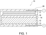
- FIG. 1 schematically illustrates an exemplary all-solid lithium battery of the present invention.
- the all-solid lithium battery 10 shown in FIG. 1 includes an oriented positive electrode plate 12, a solid electrolyte 14, and a negative electrode plate 16.
- the oriented positive electrode plate 12 is a lithium complex oxide sintered plate having a porosity of 30 to 50%.
- the lithium complex oxide sintered plate contains a plurality of primary grains composed of lithium complex oxide, and the primary grains have a mean orientation angle of more than 0° to 30° to a main face of the oriented positive electrode plate.
- This plate is a so-called "low-angle oriented positive electrode plate”.
- the solid electrolyte 14 has a melting point lower than the melting point or decomposition temperature of the oriented positive electrode plate 12 and the negative electrode plate 16.
- the negative electrode plate 16 is capable of intercalating and deintercalating lithium ions at 0.4 V or higher (vs. Li/Li + ), and contains titanium (Ti).
- the battery resistance and high-rate performance during charge/discharge cycles can be remarkably improved and the production yield can be significantly enhanced in the all-solid lithium battery including a low-angle oriented positive electrode plate and a specific solid electrolyte through adjustment of the porosity in the low-angle oriented positive electrode plate to 30 to 50% and filling 30% or more of the pores in the plate with the solid electrolyte.
- the present inventors had had an idea that an all-solid lithium battery with high performance could be manufactured with a low-angle oriented positive electrode plate, a negative electrode plate, and a solid electrolyte, as disclosed in PTLs 1 to 3, in the earliest years. Such all-solid lithium batteries had been practically manufactured. Unfortunately, it was found that some batteries among the resultant batteries had high battery resistance and significantly poor high-rate performance.
- the solid electrolyte is desired to be preliminarily softened or melted in order to increase adhesiveness at the interfaces between the positive electrode plate and the solid electrolyte and between the negative electrode plate and the solid electrolyte when batteries are manufactured using battery components as described above; however, the softened or melted electrolyte has poor wettability with the (003) plane that is predominantly exposed on the surface of the positive electrode plate, resulting in poor interfacial contact.
- interfacial separation occurs due to the stress generated during intercalation and deintercalation of lithium ions and breakdown of batteries may occur, as disclosed in PTL 1.
- the solid electrolyte 14 As described above, in the observation of a cross-section perpendicular to a main face of the oriented positive electrode plate 12, 30% or more, preferably 50% or more, more preferably 60% or more, further more preferably 70% or more of the pores contained in the oriented positive electrode plate 12 is filled with the solid electrolyte 14. Such a filling rate can further reduce the battery resistance and improve the high-rate performance during charge/discharge cycles, and enhance the production yield of batteries. In the use of an inorganic solid electrolyte, a higher filling rate of the electrolyte is preferred in the pores of the positive electrode plate 12. Although the filling rate is ideally 100%, it is practically 98% or less, more practically 95% or less.
- the filling rate (%) of the electrolyte in the pores can be determined through (i) polishing of the battery with a cross section polisher (CP), (ii) SEM observation and EDX analysis of the resultant cross-section of the oriented positive electrode plate at a specific magnification (e.g., 1000 folds) and a specific field of view (e.g., 125 ⁇ m by 125 ⁇ m), and subsequent image analysis, (iii) measurement of the area of pores filled with the solid electrolyte and the overall area of pores, and (iv) dividing the area of pores filled with the solid electrolyte by the overall area of pores and multiplying the resulting value by 100.
- CP cross section polisher
- subsequent image analysis e.g.
- the solid electrolyte 14 is in contact with preferably at least 30%, more preferably at least 40%, further more preferably at least 50% of the outer peripheral length of pores contained in the oriented positive electrode plate 12.
- Such a contact rate can further reduce the battery resistance and improve the high-rate performance during charge/discharge cycles, and further enhance the production yield of batteries. These advantages are presumably based on a further increase in the contact area between the solid electrolyte and the oriented positive electrode plate.
- a higher contact rate of the electrolyte is preferred in the pores of positive electrode plate 12.
- the contact rate (%) between the outer periphery of pores and the solid electrolyte can be determined through (i) polishing of the battery with a cross section polisher (CP), (ii) SEM observation and EDX analysis of the resultant cross-section of the oriented positive electrode plate at a specific magnification (e.g., 1000 folds) and a specific field of view (e.g., 125 ⁇ m by 125 ⁇ m), and subsequent image analysis, (iii) measurement of contact length between grains constituting the outer periphery of pores (i.e., grains adjacent to pores) and the solid electrolyte, and the outer peripheral length of pores, and (iv) dividing the contact length between the grains constituting the outer periphery of pores and the solid electrolyte by the outer peripheral length of pores and multiplying the resulting value by 100.
- CP cross section polisher
- the solid electrolyte 14 is in contact with preferably at least 20%, more preferably at least 30% of the planes other than the (003) plane of lithium complex oxide at the surface of pores included in the oriented positive electrode plate 12.
- Such a contact rate can further reduce the battery resistance and improve the high-rate performance during charge/discharge cycles, and further enhance the production yield of batteries.
- the upper limit of the contact rate, which is in contact with the solid electrolyte 14, of the planes other than the (003) plane in the lithium complex oxide is not limited. The rate is practically 98% or less, more practically 95% or less.
- the contact rate (%) between the planes other than the (003) plane and the solid electrolyte at the surface of pores can be determined through (i) polishing of the battery with a cross section polisher (CP), (ii) SEM observation, EDX analysis and EBSD measurement of the resultant cross-section of the oriented positive electrode plate at a specific magnification (e.g., 1000 folds) and a specific field of view (e.g., 125 ⁇ m by 125 ⁇ m), (iii) determination of whether the crystal planes of grains exposed at the surface of pores are the (003) planes or the planes other than the (003) plane based on the EBSD results, and measurement of the first outer peripheral length of pores where the solid electrolyte is in contact with the planes other than
- the oriented positive electrode plate 12 is a lithium complex oxide sintered plate.
- the lithium complex oxide sintered plate includes a plurality of primary grains composed of lithium complex oxide having a layered rock salt structure, and the primary grains are oriented by a mean orientation angle of more than 0° to 30° to a main face of oriented positive electrode plate.
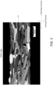
- FIG. 2 illustrates an exemplary cross-sectional SEM image perpendicular to a main face of the oriented positive electrode plate 12
- FIG. 3 illustrates a cross-sectional electron backscatter diffraction (EBSD) image perpendicular to a main face of the oriented positive electrode plate 12.
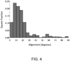
- FIG. 4 is an area-based histogram illustrating the distribution of orientation angles of primary grains 11 in the EBSD image of FIG. 3 .
- the orientation angle of each primary grain 11 is determined by the shade of color, and a darker shade indicates a smaller orientation angle.
- the orientation angle is a tilt angle of the (003) plane of each primary grain 11 to a main face of the plate.
- black portions inside the oriented positive electrode plate 12 indicate pores.
- the oriented positive electrode plate 12 is an oriented sintered plate composed of multiple primary grains 11 bonded to each other.
- Each primary grain 11 is mainly in a platy shape, and may be formed in, for example, a cuboid shape, a cubic shape, and a spherical shape.
- the cross-sectional shape of each primary grain 11 may be a rectangle, a polygon other than a rectangle, a circle, an ellipse, or any other complicated shape.
- Each primary grain 11 is composed of lithium complex oxide.
- the lithium complex oxide is an oxide represented by Li x MO 2 (0.05 ⁇ x ⁇ 1.10, M is at least one transition metal, and M typically contains at least one of Co, Ni and Mn).
- the lithium complex oxide has a layered rock salt structure.
- the layered rock salt structure is a crystal structure in which a lithium layer and a transition metal layer other than lithium are alternately stacked with an oxygen layer therebetween, i.e., a crystal structure in which a transition metal ion layer and a lithium single layer are alternately stacked with oxide ions therebetween (typically an ⁇ -NaFeO 2 structure, i.e., a structure in which transition metals and lithium metals are regularly disposed along the [111] axis of a cubic rock salt structure).
- ⁇ -NaFeO 2 structure i.e., a structure in which transition metals and lithium metals are regularly disposed along the [111] axis of a cubic rock salt structure.
- lithium complex oxides include Li x CoO 2 (lithium cobaltate), Li x NiO 2 (lithium nickelate), Li x MnO 2 (lithium manganate), Li x NiMnO 2 (lithium nickel manganate), Li x NiCoO 2 (lithium nickel cobaltate), Li x CoNiMnO 2 (lithium cobalt nickel manganate), and Li x CoMnO 2 (lithium cobalt manganate), and particularly preferably, Li x CoO 2 (lithium cobaltate, typically LiCoO 2 ).
- the lithium complex oxide may contain at least one element selected from Mg, Al, Si, Ca, Ti, V, Cr, Fe, Cu, Zn, Ga, Ge, Sr, Y, Zr, Nb, Mo, Ag, Sn, Sb, Te, Ba., Bi, and W.
- the averaged value of the orientation angles i.e., the mean orientation angle of primary grains 11 is more than 0° to 30°.
- This angle range provides the following advantages 1) to 3). 1) Since each primary grain 11 greatly tilts from the thickness direction of the positive electrode plate, the adhesiveness between the individual primary grains can be improved. This configuration can improve the lithium ion conductivity between one primary grain 11 and another primary grain 11 adjacent on two ends of the one primary grain 11 in the main face direction, resulting in an improvement in high-rate performance. 2) Cycle characteristics can be improved.
- the expansion and contraction of the oriented positive plate 12 accompanied by the expansion and contraction of each primary grain 11 in the direction perpendicular to the (003) plane depending on intercalation and deintercalation of lithium ions can be decreased in the main face direction by smaller orientation angle of the (003) plane to the main face direction, resulting in a reduction in stress generated between the oriented positive plate 12 and the solid electrolyte 14. 3)
- the high-rate performance can be further improved. This further improvement is caused by smooth intercalation and deintercalation of lithium ions in the oriented positive electrode 12, because the expansion and contraction of oriented positive electrode plate 12 proceeds more dominantly in the thickness direction than in the main face direction and thereby lithium ions can intercalate and deintercalate smoothly.
- the mean orientation angle of primary grains 11 is determined through (i) polishing of the oriented positive electrode plate with a cross section polisher (CP), (ii) EBSD analysis of the resultant cross-section of oriented positive electrode plate at a specific magnification (e.g., 1000 folds) and a specific field of view (e.g., 125 ⁇ m by 125 ⁇ m), (iii) measurement of angles between the (003) plane of primary grains and a main face of oriented positive electrode plate (i.e., tilt of crystal orientation from the (003) plane) as orientation angles based on all grains specified in the resultant EBSD image, and (iv) averaging of all the resulting angles to be a mean orientation angle.
- CP cross section polisher
- the mean orientation angle of the primary grains 11 is preferably 30° or less, and more preferably 25° or less from the viewpoint of a further improvement in high-rate performance.
- the mean orientation angle of the primary grains 11 is preferably 2° or more, and more preferably 5° or more from the viewpoint of a further improvement in high-rate performance.
- the orientation angle of each primary grain 11 may be widely distributed from 0° to 90°, and most of the orientation angles are preferably distributed in a region of more than 0° to 30°.
- the total area of primary grains 11 that have the orientation angle of more than 0° to 30° to a main face of the oriented positive electrode plate 12 (hereinafter, referred to as low-angle primary grains) is preferably 70% or more, and more preferably 80% or more of the total area of the primary grains 11 (specifically, 30 primary grains 11 used in calculation of the mean orientation angle) included in the cross-section.
- the total area of the low-angle primary grains having an orientation angle of 20° or less is more preferably 50% or more of the total area of the 30 primary grains 11 used in the calculation of the mean orientation angle.
- the total area of the low-angle primary grains having an orientation angle of 10° or less is more preferably 15% or more of the total area of the 30 primary grains 11 used in the calculation of the mean orientation angle.
- each primary grain 11 is mainly platy
- the cross-section of each primary grain 11 respectively extends in a predetermined direction as shown in FIGS. 2 and 3 , and typically has a substantially rectangular shape.
- the total area of primary grains 11 that have an aspect ratio of 4 or more among the primary grains 11 included in the analyzed cross-section is preferably 70% or more, and more preferably 80% or more of the total area of the primary grains 11 (specifically, 30 primary grains 11 used in calculation of the mean orientation angle) included in the cross-section.
- the configuration shown in the EBSD image of FIG. 3 can increase the mutual adhesiveness between the primary grains 11, resulting in a further improvement of high-rate performance.
- the aspect ratio of the primary grains 11 is a value determined by dividing the maximum Feret diameter by the minimum Feret diameter of the primary grains 11.
- the maximum Feret diameter is the maximum distance between two parallel straight lines by which the primary grains 11 are sandwiched in the EBSD image from cross-sectional observation.
- the minimum Feret diameter is the minimum distance between two parallel straight lines by which the primary grains 11 are sandwiched.
- a plurality of primary grains constituting the oriented sintered plate has a mean grain diameter of preferably 20 ⁇ m or less.
- the primary grains 11 has a mean grain diameter of preferably 20 ⁇ m or less, more preferably 15 ⁇ m or less.
- Such a diameter range can reduce the distance for lithium ions to travel in the primary grains 11, resulting in a further improvement in high-rate performance.
- the lithium ions move from the inside of primary grains 11 to the solid electrolyte in the pores of the positive electrode, further pass through the film-shaped (or planar) solid electrolyte 14 and move into the grains of negative electrode as a counter electrode.
- the mean grain diameter of primary grains 11 can be measured by the analysis of a cross-sectional SEM image of the sintered plate.
- the sintered plate is processed with a cross section polisher (CP) to expose a polished cross-section.
- the polished cross-section is observed by SEM (scanning electron microscopy) at a specific magnification (e.g., 1000 folds) and a specific field of view (e.g., 125 ⁇ m by 125 ⁇ m).
- the field of view is selected such that 20 or more primary grains are located in this field.
- circumscribed circles are drawn for all primary grains and the diameters of circumscribed circles are measured and averaged to be a mean grain diameter of primary grains.
- the lithium complex oxide sintered plate constituting the oriented positive electrode plate 12 has a porosity of 30 to 50%. Such a porosity range can sufficiently fill the pores in the oriented positive electrode plate 12 with the solid electrolyte 14, resulting in a significant reduction in the battery resistance and an improvement in the high-rate performance during charge/discharge cycles, and a remarkable enhancement in the production yield of batteries.
- the porosity in the oriented positive electrode plate 12 indicates the volume rate of pores in the oriented positive electrode plate 12. This porosity can be determined by the analysis in a cross-sectional SEM image of the oriented positive electrode plate.
- the porosity (%) can be determined through (i) processing of the sintered plate with a cross section polisher (CP) to expose a polished cross-section, (ii) scanning electron microscope (SEM) observation of the polished cross-section at a specific magnification (e.g., 1000 folds) and a specific field of view (e.g., 125 ⁇ m by 125 ⁇ m), and (iii) analysis of the resultant SEM image, and dividing the total area of all the pores in the field of view by the total area (i.e., cross-sectional area) of the sintered plate in the field of view and further multiplying the resulting value by 100.
- CP cross section polisher
- SEM scanning electron microscope
- the oriented positive electrode plate 12 has a thickness of 30 ⁇ m or more, preferably 40 ⁇ m or more, particularly preferably 50 ⁇ m or more, most preferably 55 ⁇ m or more from the viewpoint of an increase in the active material capacity per unit area and an increase in energy density of the all-solid lithium battery 10.
- the upper limit of the thickness is not limited.
- the oriented positive electrode plate 12 has a thickness of preferably less than 500 ⁇ m, more preferably less than 200 ⁇ m, further more preferably 150 ⁇ m or less, particularly preferably 120 ⁇ m or less, particularly more preferably 100 ⁇ m or less, most preferably 90 ⁇ m or less, 80 ⁇ m or less, or 70 ⁇ m or less from the viewpoint of restraint in deterioration of battery properties (particularly, an increase in electrical resistance) due to repeated charge/discharge cycles.
- the oriented positive electrode plate has dimensions of preferably 5 mm by 5 mm or more, more preferably 10 mm by 10 mm or more.
- the oriented positive electrode plate has an area of preferably at least 25 mm 2 , more preferably at least 100 mm 2 .
- a face, remote from the solid electrolyte 14, of the oriented positive electrode plate 12 is preferably provided with a positive electrode collector 13.
- a face, remote from the solid electrolyte 14, of the negative electrode plate 16 is preferably provided with a negative electrode collector 17.
- the material constituting the positive electrode collector 13 and the negative electrode collector 17 include platinum (Pt), platinum (Pt)/palladium (Pd), gold (Au), silver (Ag), aluminum (Al), copper (Cu), and ITO (indium-tin oxide film).
- the oriented positive electrode plate 12, the solid electrolyte 14, and the negative electrode plate 16 are accommodated in a container 18.
- the container 18 may be of any type that can accommodate a unit cell or a laminated battery that a plurality of the unit cells is stacked in series or in parallel.
- the container 18 since an all-solid lithium battery 10 has no risk of electrolyte leakage, the container 18 may be of a relatively simple type, and the cell or battery may be packaged with a cover material.
- the all-solid lithium battery can be manufactured in a chip form for mounting on an electronic circuit or in a laminate cell form (e.g., a multilayer product of aluminum (Al)/polypropylene (PP)) for low-profile and broad space applications.
- the positive electrode collector 13 and/or the negative electrode collector 17 may have a structure that can serve as a part of the container 18.
- a heat-resistant resin such as polychlorotrifluoroethylene (PCTFE), tetrafluoroethylene-perfluoroalkylvinyl ether copolymer (PFA), polyimide, and polyamide, may be used in place of polypropylene, and a metal, for example, aluminum or stainless steel, may also be used after ensuring insulation between the cover material and the collector.
- PCTFE polychlorotrifluoroethylene
- PFA tetrafluoroethylene-perfluoroalkylvinyl ether copolymer
- polyimide polyimide
- polyamide polyamide
- the solid electrolyte 14 is a lithium ion conductive material having a melting point lower than the melting point or pyrolytic temperature of the oriented positive electrode plate 12 or the negative electrode plate 16.
- the solid electrolyte 14 typically has a higher melting point than the operational temperature of the battery, and specifically has a melting point higher than the operational temperature of the battery and not higher than 600°C. Since such a solid electrolyte 14 has a low melting point, the solid electrolyte can melt at a temperature of 100 to 600°C and permeate into the pores of the oriented positive electrode plate 12 and the pores of the negative electrode plate 16 if desired, as described later, resulting in strong interfacial contact.
- the solid electrolyte 14 is represented by the formulas specified in claim 1.
- the solid electrolyte 14 may contain a different lithium halide-based material.
- the lithium halide-based materials include one selected from the group consisting of Li 3 OCl, Li (3-x) M x/2 OA (where 0 ⁇ x ⁇ 0.8, M is at least one selected from the group consisting of Mg, Ca, Ba and Sr, and A is at least one selected from the group consisting of F, Cl, Br and I), Li 2 (OH) 1-a F a Cl (where 0 ⁇ a ⁇ 0.3), and Li 2 OHX (where X is Cl and/or Br), and Li 3 OCl or Li 2 (OH) 0.9 F 0.1 Cl.
- the solid electrolyte 14 may be a material other than the lithium halide-based material.
- a typical form of the solid electrolyte 14 is a solid electrolyte layer.
- the solid electrolyte layer can be produced by any process. Suitable examples of such processes include vapor phase deposition, such as sputtering and CVD; liquid phase deposition, such as screen printing and spin coating; compression of powder; heating of a raw material to a temperature above the melting point and then solidification of the melt; and heating of compressed raw powder to a temperature above the melting point and then solidification of the melt.
- the solid electrolyte 14 has a low melting point as described above, the solid electrolyte can melt at a temperature of 100 to 600°C and permeate into the pores of the oriented positive electrode plate 12 and the pores of the negative electrode plate 16 if desired, as described later, resulting in strong interfacial contact.
- the electrolyte is a melt-solidified material composed of Li 3 OCl.
- the solid electrolyte 14 may be one melt-solidified material selected from the group consisting of Li 3 OCl, Li (3-x) M x/2 OA (where 0 ⁇ x ⁇ 0.8, M is at least one selected from the group consisting of Mg, Ca, Ba and Sr, and A is at least one selected from the group consisting of F, Cl, Br and I), Li 2 (OH) 1-a F a Cl (where 0 ⁇ a ⁇ 0.3), and Li 2 OHX (where X is Cl and/or Br).
- M is at least one selected from the group consisting of Mg, Ca, Ba and Sr
- A is at least one selected from the group consisting of F, Cl, Br and I
- Li 2 (OH) 1-a F a Cl where 0 ⁇ a ⁇ 0.3
- Li 2 OHX where X is Cl and/or Br
- the solid electrolyte 14 may have any dimension.
- the solid electrolyte has a thickness of preferably 0.0005 mm to 1.0 mm, more preferably 0.001 mm to 0.1 mm, further more preferably 0.002 to 0.05 mm in a region other than the permeated portion of the solid electrolyte into the pores of the oriented positive electrode plate 12 and the pores of the negative electrode plate 16 from the viewpoint of high-rate performance during charge/discharge cycles and mechanical strength.
- the thickness of the solid electrolyte layer may be controlled by a layering process, or with spacers in the case of heating of compressed raw powder to a temperature above the melting point and then solidification of the melt.
- the all-solid lithium battery preferably includes spacers for defining the thickness of the solid electrolyte layer 14 between the oriented positive electrode plate 12 and the negative electrode plate 16.
- the spacers have an electrical resistivity of preferably 1 ⁇ 10 5 ⁇ cm or more, and more preferably 1 ⁇ 10 7 ⁇ cm or more.
- the spacers are composed of any material, preferably composed of ceramic, such as Al 2 O 3 , MgO, and ZrO 2 .
- the negative electrode plate 16 can intercalate and deintercalate lithium ions at 0.4 V or more based on Li/Li + and contains Ti.
- a preferred negative electrode active material satisfying such conditions is an oxide containing at least Ti.
- Preferred examples of such a negative electrode active material include lithium titanate Li 4 Ti 5 O 12 (hereinafter referred to as "LTO"), niobium titanium complex oxide Nb 2 TiO 7 , and titanium oxide TiO 2 . More preferred examples of the negative electrode active material include LTO and Nb 2 TiO 7 .
- a further preferred example of the negative electrode active material is LTO.
- Typical LTO is known to have a spinel structure. Alternatively, LTO may have a different structure during the charging/discharging cycles of the battery.
- LTO may have two phases consisting of Li 4 Ti 5 O 12 having a spinel structure and Li 7 Ti 5 O 12 having a rock-salt structure during the charging/discharging cycles, and the reaction continues between the two phases.
- LTO may have any structure other than the spinel structure.
- the negative electrode plate 16 is preferably composed of a sintered plate containing, for example, LTO or Nb 2 TiO 7 . Since the negative electrode plate composed of a sintered plate contains no binder, high capacity and satisfactory charge/discharge efficiency can be achieved due to a high packing density of the negative-electrode active material, for example, LTO or Nb 2 TiO 7 . The binder in the green sheet will eventually disappear or burn while the green sheet is fired into the negative electrode plate.
- the LTO sintered plate can be produced by a process disclosed in PTL 2 ( JP2015-185337A ).
- the negative electrode plate 16 may have high compactness or some pores.
- the pores, if contained, in the negative electrode plate can sufficiently (or uniformly) release the stress generated by the expansion and contraction of crystal lattices accompanied by the intercalation and deintercalation of lithium ions in the charge/discharge cycles, resulting in an effective reduction in cracking at grain boundaries accompanied by repeated charge/discharge cycles.
- the negative electrode plate 16 has a porosity of preferably 2 to 40%, more preferably 3 to 30%. Such a porosity range can desirably achieve the stress relaxation by the pores and high energy capacity.
- the porosity of the negative electrode plate 16 is a volume rate of the pores in the negative electrode plate 16, and can be determined by the analysis of a cross-sectional SEM image of the negative electrode plate 16 similar to the porosity of the oriented positive electrode plate 12 as described above.
- the solid electrolyte 14 occupies 30% or more, preferably 50% or more, more preferably 60% or more, further more preferably 70% or more of the pores contained in the negative electrode plate 12.
- a filling rate can further reduce the battery resistance and improve the high-rate performance during charge/discharge cycles, and further enhance the production yield of batteries.
- a higher filling rate of the electrolyte is preferred in the pores of the positive electrode plate 12.
- the filling rate is ideally 100%, it is practically 99% or less, more practically 95% or less.
- the filling rate (%) of the electrolyte in the pores can be determined through the analysis of the cross-sectional SEM image of the negative electrode plate 16, as in the analysis of the oriented positive electrode plate 12 as described above.
- the solid electrolyte 14 is in contact with preferably at least 30%, more preferably at least 40%, further more preferably at least 50% of the outer peripheral length of the pores contained in the negative electrode plate 12.
- a contact rate can further reduce the battery resistance and improve the high-rate performance during charge/discharge cycles, and further enhance the production yield of batteries. Accordingly, the contact area further increases between the solid electrolyte and the negative electrode plate.
- a higher contact rate of the electrolyte is preferred in the pores of the negative electrode plate 16.
- the contact rate (%) between the outer periphery of the pores and the solid electrolyte can be determined through the analysis of the cross-sectional SEM image of the negative electrode plate 16, as in the analysis of the oriented positive electrode plate 12 as described above.
- the negative electrode plate 16 has a thickness of 25 ⁇ m or more, preferably 30 ⁇ m or more, more preferably 40 ⁇ m or more, particularly preferably 50 ⁇ m or more, mostly preferably 55 ⁇ m or more from the viewpoint of an increase in the active material capacity per unit area and an increase in energy density of the all-solid lithium battery 10.
- the thickness of the negative electrode plate 16 may have any upper limit.
- the negative electrode plate 16 has a thickness of preferably 400 ⁇ m or less, more preferably 300 ⁇ m or less to reduce the deterioration of the battery properties accompanied by repeated charge/discharge cycles (particularly, due to an increase in electric resistance).
- the negative electrode plate 16 has dimensions of preferably 5 mm by 5 mm or more, more preferably 10 mm by 10 mm or more. In another expression, the negative electrode plate 16 has an area of preferably at least 25 mm 2 , more preferably at least 100 mm 2 .
- the oriented positive electrode plate 12 is preferably a LiCoO 2 (LCO) sintered plate
- the negative electrode plate 16 is preferably a Li 4 Ti 5 O 12 (LTO) sintered plate.
- an averaged value of the orientation angles i.e., a mean orientation angle of more than 0° to 30° in the LCO oriented positive electrode plate causes no expansion and contraction to occur in the main face direction during charge/discharge cycles, and the LTO negative electrode plate and the solid electrolyte also do not expand and contract during the charge/discharge cycles, resulting in no stress generation (in particular, the stress at the interface between the oriented positive electrode plate 12 or negative electrode plate 16 and the solid electrolyte 14) and stable charge and discharge.
- Nb 2 TiO 7 sintered plate in the negative electrode plate 16 primary grains constituting the Nb 2 TiO 7 sintered plate are preferably oriented to reduce the expansion and contraction.
- the all-solid lithium battery of the present invention preferably charges or discharges at 100°C or more.
- a temperature of 100°C or more can achieve rapid charge/discharge at a high cycle capacity retention rate.
- a temperature of 100°C or more enables the all-solid lithium battery 10 to rapidly charge or discharge. That is, the all-solid lithium battery can run stably at a high rate at this temperature. Repeated charge/discharge can retain high capacity. In other words, a high cycle capacity retention rate can be achieved.
- the operational temperature of the all-solid lithium battery during the charge/discharge cycles is preferably 100°C or more, more preferably 100 to 300°C, further preferably 100 to 200°C, particularly preferably 100 to 150°C.
- a heating means achieving such an operational temperature include various heaters and exothermic devices.
- Preferred examples of the heating means are electroconductive ceramic heaters.
- the all-solid lithium battery of this embodiment is preferably provided as a secondary battery system including a heating means.
- the inventive all-solid lithium battery 10 is preferably produced as follows: Solid electrolyte powder containing at least one selected from the group consisting of xLiOH ⁇ yLi 2 SO 4 and Li a (OH) b F c Br is placed on the oriented positive electrode plate 12 (or the negative electrode plate 16). The negative electrode plate 16 (or the oriented positive electrode plate 12) is placed on the solid electrolyte powder. The negative electrode plate 16 is pressed toward the oriented positive electrode plate 12 (or the oriented positive electrode plate is pressed toward the negative electrode plate) at 100 to 600°C, preferably 200 to 500°C, more preferably 250 to 450°C to melt the solid electrolyte powder and permeate the melt into the pores in the oriented positive electrode plate.
- This press treatment is performed by any process that can generate a load, for example, a mechanical load or weight. Subsequently, the oriented positive electrode plate 12, the molten electrolyte, and the negative electrode plate 16 are spontaneously or controllably cooled to solidify the molten electrolyte into the solid electrolyte 14.
- the all-solid lithium battery 10 may include spacers that define the thickness of the solid electrolyte layer 14 between the oriented positive electrode plate 12 and the negative electrode plate 16. This configuration is preferably achieved by disposing spacers along with the solid electrolyte powder between the oriented positive electrode plate 12 and the negative electrode plate 16.
- LiCoO 2 is abbreviated as “LCO” and Li 4 Ti 5 O 12 is abbreviated as “LTO”. Only examples 8-10, 13 and 14 are according to the invention. All other examples are not according to the invention.
- Co 3 O 4 powder available from Seido Chemical Co., Ltd., a mean particle size of 0.9 ⁇ m
- Li 2 CO 3 powder available from The Honjo Chemical Corporation
- the resultant powder was pulverized in a pot mill into a volume-based D50 of 0.4 ⁇ m, to give LCO powder composed of platy particles.
- the resultant LCO powder 100 parts by weight
- a binder polyvinyl butyral: Product No.
- BM-2 available from Sekisui Chemical Co., Ltd.
- a plasticizer di-2-ethylhexyl phthalate (DOP), available from Kurogane Kasei Co., Ltd.
- a dispersant product name: RHEODOL SP-O30, available from Kao Corporation (2 parts by weight) (2 parts by weight) were mixed.
- the mixture was defoamed by stirring under reduced pressure to prepare an LCO slurry with a viscosity of 4000 cP.
- the viscosity was measured with an LVT viscometer available from Brookfield.
- the slurry was molded into an LCO green sheet onto a PET film by a doctor blade process.
- the dried thickness of the LCO green sheet was 50 ⁇ m.
- Li 2 CO 3 raw material powder (volume-based particle diameter D50: 2.5 ⁇ m, available from The Honjo Chemical Corporation) (100 parts by weight), a binder (poly(vinyl butyral): Product No. BM-2, available from Sekisui Chemical Co., Ltd.) (5 parts by weight), a plasticizer di-2-ethylhexyl phthalate (DOP), available from Kurogane Kasei Co., Ltd.) (2 parts by weight), and a dispersant (RHEODOL SP-O30, available from Kao Corporation) (2 parts by weight) were mixed. The mixture was defoamed by stirring under reduced pressure to prepare a Li 2 CO 3 slurry with a viscosity of 4000 cP.
- a binder poly(vinyl butyral): Product No. BM-2, available from Sekisui Chemical Co., Ltd.
- DOP plasticizer di-2-ethylhexyl phthalate
- RHEODOL SP-O30 available
- the viscosity was measured with an LVT viscometer available from Brookfield.
- the Li 2 CO 3 slurry was molded into a Li 2 CO 3 green sheet on a PET film by a doctor blade process.
- the dried thickness of the Li 2 CO 3 green sheet was adjusted such that the Li/Co molar ratio of the Li content in the Li 2 CO 3 green sheet to the Co content in the LCO green sheet was 0.2.
- the LCO green sheet was separated from the PET film, and was cut into a 50 mm square. The cut piece was placed on the center of a bottom magnesia setter (dimensions: 90 mm square, height: 1 mm). The LCO green sheet was heated to 600°C at a heating rate of 200°C/h, and was degreased for three hours. The LCO green sheet was then kept at 900°C for three hours to calcine the LCO green sheet. The dried Li 2 CO 3 green sheet was cut into a size such that the Li/Co molar ratio of the Li content in the Li 2 CO 3 green sheet to the Co content in the calcined LCO plate was 0.5.
- the laminate was heated to 600°C at a heating rate of 200°C/h, and was degreased for three hours. The laminate was then heated to 800°C at 200°C/h, and was kept for five hours.
- the laminate was then heated to 900°C at 200°C/h, and was kept for 24 hours to fire. After the firing, the fired laminate was cooled to room temperature, and was removed from the alumina sheath. Thus, the sintered LCO plate was yielded as a positive electrode plate.
- An Au film (a thickness of 100 nm) as a current collecting layer was deposited by sputtering on a face, in contact with the bottom setter, of the sintered LCO plate, and the LCO positive electrode plate was then cut into a 10 mm by 10 mm square by a laser process.
- a binder poly(vinyl butyral): product number BM-2, available from Sekisui Chemical Co., Ltd.
- DOP di(2-ethylhexyl) phthalate, available from Kurogane Kasei Co., Ltd.
- the resultant mixture of raw materials for the negative electrode was stirred and defoamed under reduced pressure, and then the viscosity was adjusted to 4000 cP to prepare LTO slurry.
- the viscosity was measured with an LVT viscometer available from Brookfield.
- the resulting slurry was applied onto a PET film by a doctor blade process into an LTO green sheet.
- the dried thickness of LTO green sheet was adjusted such that the fired thickness was 50 ⁇ m.
- the resultant green sheet was cut into a 25 mm square with a box knife and placed onto an embossed zirconia setter.
- the green sheet on the setter was placed into an alumina sheath and held at 500°C for five hours, then heated at a rate of 200°C/h and fired at 800°C for five hours.
- An Au film (a thickness of 100 nm) as a current collecting layer was deposited on a face, in contact with the setter, of the resultant LTO sintered plate by sputtering, and the LTO sintered plate was then cut into a 10 mm by 10 mm by a laser process.
- An aqueous raw material solution was prepared by dissolving of LiOH (4.790 g) and LiCl (4.239 g) into a small amount of deionized water. Each amount of these precursors was determined such that the stoichiometric ratio corresponded to the reactant formula: Li 3 OCl + H 2 O. Most of the water was removed with a rotary evaporator and a bath at about 90°C. The resulting solid was placed in an alumina boat. The boat was disposed in an electric furnace and heated in vacuum at about 280°C for about 48 hours to give Li 3 OCl powder, which is a reaction product, as a solid electrolyte.
- the Li 3 OCl powder was placed on the positive electrode plate; the positive electrode plate and the Li 3 OCl powder were heated at 400°C on a hot plate; and the negative electrode plate was placed while being pressed from the top. At this time, the Li 3 OCl powder was melted followed by solidification, and a solid electrolyte layer having a thickness of 20 ⁇ m was thereby formed.
- the unit cells composed of the positive electrode plate, the solid electrolyte and the negative electrode plate were used to prepare 100 laminated batteries.
- Each of the LCO positive electrode plate and the LTO negative electrode plate was polished with a cross section polisher (CP) (IB-15000CP, available from JEOL Ltd.), and the resultant cross-section of the electrode plate was observed with a SEM (JSM6390LA, available from JEOL Ltd.) at a 1000-fold field of view (125 ⁇ m by 125 ⁇ m). The image analysis was then performed, and the porosity (%) of each electrode plate was determined through dividing the area of all the pores by the total area of each plate and multiplying the resulting value by 100.
- CP cross section polisher
- SEM JSM6390LA
- the sintered LCO plate was polished with a cross section polisher (CP) (IB-15000CP, available from JEOL Ltd.), and the resultant cross-section of the positive electrode plate (cross-section perpendicular to a main face of the positive electrode plate) was subjected to the EBSD measurement at a 1000-fold field of view (125 ⁇ m by 125 ⁇ m) to give an EBSD image.
- CP cross section polisher
- This EBSD measurement was performed using a Schottky field emission scanning electron microscope (model JSM-7800F, available JEOL Ltd.).
- the angle defined by the (003) plane of the primary grain and the main face of the positive electrode plate is determined as a tilt angle.
- the mean value of the angles was determined as a mean orientation angle (i.e., a mean tilt angle) of the primary grains.
- the prepared battery was polished with a cross section polisher (CP) (IB-15000CP, available from JEOL Ltd.), and the resultant cross-section of the positive electrode plate or negative electrode plate was observed with a SEM (JSM6390LA, available from JEOL Ltd.) and analyzed with an EDX at a 1000-fold field of view (125 ⁇ m by 125 ⁇ m).
- the image analysis was then performed, and the area of the pores filled with the solid electrolyte and the area of all pores were measured, the area of all pores being the total area of the area of the pores filled with the solid electrolyte and the area of the pores not filled with the solid electrolyte.
- the filling rate of electrolyte (%) in the pores was determined through dividing the area of the pores filled with the solid electrolyte by the area of all the pores and multiplying the resulting value by 100.
- the prepared battery was polished with a cross section polisher (CP) (IB-15000CP, available from JEOL Ltd.), and the resultant cross-section of the positive electrode plate or negative electrode plate was observed with a SEM (JSM6390LA, available from JEOL Ltd.) and analyzed with an EDX at a 1000-fold field of view (125 ⁇ m by 125 ⁇ m).
- CP cross section polisher
- the image analysis was then performed, and the contact length between the grains constituting the outer periphery of the pores (i.e., grains adjacent to the pores) and the solid electrolyte and the outer peripheral length of the pores was measured, the outer peripheral length being the total length of the contact length between the grains constituting the outer periphery of pores and the solid electrolyte, and the non-contact length between the grains constituting the outer periphery of pores and the solid electrolyte.
- the contact rate (%) between the outer periphery of pores and the solid electrolyte was determined thorough dividing the contact length between the grains constituting the outer periphery of pores and the solid electrolyte by the outer peripheral length of pores and multiplying the resulting value by 100.
- the prepared battery was polished with a cross section polisher (CP) (IB-15000CP, available from JEOL Ltd.), and the resultant cross-section of the positive electrode plate was observed with a SEM (JSM6390LA, available from JEOL Ltd.), analyzed with an EDX and measured with an EBSD at a 1000-fold field of view (125 ⁇ m by 125 ⁇ m).
- the EBSD measurement was performed as in the measurement of the mean orientation angle of primary grains as described above.
- the crystal planes of grains exposed at the surface of pores are the (003) planes or the planes other than the (003) plane was determined, and the first outer peripheral length of pores where the solid electrolyte is in contact with the planes other than the (003) plane and the second outer peripheral length of pores where the planes other than the (003) plane are exposed are measured based on the EBSD results.
- the contact rate (%) between the planes other than (003) plane and the solid electrolyte at the surface of pores was determined through dividing the first outer peripheral length of pores where the solid electrolyte is in contact with the planes other than the (003) plane by the second outer peripheral length of pores where the planes other than the (003) plane are exposed and multiplying the resulting value by 100.
- Each battery resistance of 100 prepared batteries was measured by AC impedance spectroscopy using an electrochemical measurement system SP-150 available from BioLogic. The minimum value among 100 batteries was defined as the reference resistance. The batteries having a resistance value within ten times the reference resistance were determined to be non-defective products, and the number of non-defective products was defined as the production yield of batteries.
- the cycle capacity retention of the battery was measured in a potential range of 2.7 V to 1.5 V at a battery operational temperature of 100°C in accordance with the following procedures.
- Batteries were prepared and evaluated as in Example 1 except that the keeping at 800°C for five hours was not performed during the firing in Procedure (1c) and the heating was performed at 330°C in Procedure (4).
- an LTO sintered plate was produced as in Example 1 except that another LTO powder (a volume-based D50 particle size of 0.7 ⁇ m, available from Ishihara Sangyo Co., Ltd.) was used in the LTO raw powder.
- another LTO powder a volume-based D50 particle size of 0.7 ⁇ m, available from Ishihara Sangyo Co., Ltd.
- Batteries were prepared and evaluated in Example 1 except that a LiOH ⁇ Li 2 SO 4 -based powder produced as follows was used in the solid electrolyte, and the batteries were prepared as follows:
- LiOH purity ⁇ 98.0%) and Li 2 SO 4 (purity ⁇ 98.0%) were provided. These raw materials are weighed into a LiOH:Li 2 SO 4 molar ratio of 3.0:1.0 and mixed in an Ar atmospheric glove box having a dew point of -50°C or lower. The mixture was placed in a glass tube in an Ar atmosphere and melted by heating at 430°C for two hours. The glass tube was then placed into water and kept for ten minutes, and the melt was quenched to form a solidified material. The solidified material was then pulverized in a mortar in an Ar atmosphere to give 3LiOH ⁇ Li 2 SO 4 powder, which is a solid electrolyte.
- a LiOH ⁇ Li 2 SO 4 -based powder containing ZrO 2 beads (5 wt%) having a diameter of 30 ⁇ m was placed on the positive electrode plate, and the negative electrode plate was then placed on the powder.
- the resulting unit cells composed of the positive electrode plate, the solid electrolyte, and the negative electrode plate were used to produce 100 laminated batteries.
- An LTO sintered plate was produced as in Example 1 except that the firing was performed for five hours at a maximum temperature of 775°C in Procedure (2b).
- Batteries were prepared and evaluated as in Example 8 except that the thickness of the LCO sintered plate was 200 ⁇ m and the thickness of the LTO sintered plate was 200 ⁇ m.
- Batteries were prepared and evaluated as in Example 7 except that positive and negative electrode plates were produced as in Example 6, and Li(OH) 0.9 F 0.1 Cl-based powder produced as follows was used in the solid electrolyte, and the solid electrolyte powder was heated at 350°C for 45 minutes in Procedure (4).
- LiOH purity ⁇ 98.0%
- LiCl purity ⁇ 99.9%
- each raw material was weighed into a LiOH:LiCl:LiF molar ratio of 0.9:1.0:0.1 and mixed.
- Batteries were prepared and evaluated as in Example 7 except that positive and negative electrode plates were produced as in Example 6, Li(OH) 0.9 F 0.1 Br-based powder produced as follows was used in the solid electrolyte, and the solid electrolyte powder was heated at 350°C for 45 minutes in Procedure (4).
- LiOH purity ⁇ 98.0%
- LiBr purity ⁇ 99.9%
- each raw material was weighed into a LiOH:LiBr:LiF molar ratio of 0.9:1.0:0.1 and mixed.
- This quartz tube was fixed in a tubular furnace and heated at 350°C for 30 minutes. During this heating, an Ar gas having a dew point of -50°C or lower was injected through a gas inlet at the flange and discharged from a gas outlet, and the mixed powder was stirred. After cooling, the gas inlet and the gas outlet were closed, and the quartz tube was returned into the Ar atmospheric glove box having a dew point of -50°C or lower and the crucible was recovered. The reactant composite was collected from the crucible and pulverized in a mortar to give Li 2 (OH) 0.9 F 0.1 Br powder, which is a solid electrolyte.
- the heating temperature and time in an Ar gas atmosphere can be changed as appropriate. In general, the heating temperature should be 250°C to 600°C, and the heating time should be 0.1 hours or longer.
- the resultant mixture was defoamed by stirring under reduced pressure to prepare an Li(Co,Ni,Mn)O 2 slurry with an adjusted viscosity.
- the slurry as prepared above was shaped into a green sheet onto a PET film by a doctor blade process.
- the thickness of the LCO green sheet was adjusted such that the fired thickness was 50 ⁇ m.
- the Li(Co,Ni,Mn)O 2 green sheet separated from the PET film was cut out.
- a cut piece of green sheet was placed on the center of a bottom magnesia setter, and a porous top magnesia setter was placed on the piece.
- the cut piece of green sheet sandwiched between two setters was placed in an alumina sheath. In this step, the alumina sheath was loosely capped with a small gap.
- the resultant laminate was heated to 600°C at a rate of 200°C/h, degreased for three hours, and then fired at 800°C for 20 hours to give a Li(Co,Ni,Mn)O 2 sintered plate.
- the resulting sintered plate was then cut into a 10 mm by 10 mm by a laser process to produce a positive electrode plate.
- LCO 15 30 LTO 30 Li 2 (OH) 0.9 F 0.1 Cl 85 71 37 Ex. 14 LCO 15 30 LTO 30 Li 2 (OH) 0.9 F 0.1 Br 86 75 35 Ex. 15 Li(Co,Ni,Mn)O 15 20 LTO 30 3LiOH ⁇ Li 2 SO 4 82 68 35 *: Comparative examples : LCO indicates LiCoO 2 ; Li(Co,Ni,Mn)O indicates Li(Co 0.90 Ni 0.05 Mn 0.05 )O 2 ; and LTO indicates Li 4 Ti 5 O 12 .
Landscapes
- Chemical & Material Sciences (AREA)
- General Chemical & Material Sciences (AREA)
- Chemical Kinetics & Catalysis (AREA)
- Electrochemistry (AREA)
- Engineering & Computer Science (AREA)
- Manufacturing & Machinery (AREA)
- Inorganic Chemistry (AREA)
- Materials Engineering (AREA)
- Physics & Mathematics (AREA)
- Condensed Matter Physics & Semiconductors (AREA)
- General Physics & Mathematics (AREA)
- Ceramic Engineering (AREA)
- Secondary Cells (AREA)
- Battery Electrode And Active Subsutance (AREA)
- Cell Separators (AREA)
Claims (20)
- Festkörper-Lithiumbatterie, umfassend:eine ausgerichtete positive Elektrodenplatte, die eine gesinterte Lithiumkomplexoxidplatte mit einer Porosität von 30 bis 50 % ist, wobei die Porosität wie in der Beschreibung beschrieben bestimmt wird, und wobei die gesinterte Lithiumkomplexoxidplatte eine Vielzahl von primären Körnern enthält, die aus Lithiumkomplexoxid bestehen, das eine geschichtete Steinsalzstruktur aufweist, und wobei die primären Körner in einem mittleren Ausrichtungswinkel von mehr als 0° bis 30° zu einer Hauptfläche der ausgerichteten positiven Elektrodenplatte ausgerichtet sind, wobei der Ausrichtungswinkel ein Neigungswinkel der Ebene (003) jedes primären Korns zu einer Hauptfläche der ausgerichteten positiven Elektrodenplatte ist, der wie in der Beschreibung beschrieben bestimmt wird;eine negative Elektrodenplatte, die Ti enthält und dazu in der Lage ist, Lithiumionen bei 0,4 V oder mehr (vs. Li/Li+) zu interkalieren und deinterkalieren; undeinen festen Elektrolyten, der einen Schmelzpunkt aufweist, der niedriger ist als ein Schmelzpunkt oder eine Zersetzungstemperatur der ausgerichteten positiven Elektrodenplatte und der negativen Elektrodenplatte, wobei zumindest 30 % der Poren in der ausgerichteten positiven Elektrodenplatte in einer Perspektive eines Querschnitts normal auf eine Hauptfläche der ausgerichteten positiven Elektrodenplatte mit dem festen Elektrolyten gefüllt sind,(i) wobei der feste Elektrolyt durch eine Formel xLiOH·yLi2SO4 dargestellt ist, worin x + y = 1 ist und 0,6 ≤ x ≤ 0,95 ist, oder(ii) wobei der feste Elektrolyt durch eine Formel Lia(OH)bFcBr dargestellt ist, worin 1,8 ≤ a ≤ 2,3 ist, b = a-c-1 ist und 0,01 ≤ c ≤ 0,11 ist, und eine Antiperovskit-Kristallphase umfasst.
- Festkörper-Lithiumbatterie nach Anspruch 1, wobei der Schmelzpunkt des festen Elektrolyten höher ist als eine Betriebstemperatur von Batterien und 600 °C oder weniger beträgt.
- Festkörper-Lithiumbatterie nach Anspruch 1 oder 2, wobei zumindest 70 % der Poren in der ausgerichteten positiven Elektrodenplatte mit dem festen Elektrolyten gefüllt sind.
- Festkörper-Lithiumbatterie nach einem der Ansprüche 1 bis 3, wobei zumindest 30 % einer Außenumfangslänge von Poren in der ausgerichteten positiven Elektrodenplatte in einer Perspektive eines Querschnitts normal auf eine Hauptfläche der ausgerichteten positiven Elektrodenplatte mit dem festen Elektrolyten in Kontakt stehen.
- Festkörper-Lithiumbatterie nach Anspruch 4, wobei zumindest 50 % der Außenumfangslänge von Poren in der ausgerichteten positiven Elektrodenplatte mit dem festen Elektrolyten in Kontakt stehen.
- Festkörper-Lithiumbatterie nach einem der Ansprüche 1 bis 5, wobei zumindest 20 % von Ebenen, die nicht die Ebene (003) des Lithiumkomplexoxids sind, an der Oberfläche von Poren in der ausgerichteten positiven Elektrodenplatte in einer Perspektive eines Querschnitts normal auf eine Hauptfläche der ausgerichteten positiven Elektrodenplatte mit dem festen Elektrolyten in Kontakt stehen.
- Festkörper-Lithiumbatterie nach Anspruch 6, wobei zumindest 30 % von Ebenen, die nicht die Ebene (003) des Lithiumkomplexoxids sind, an der Oberfläche von Poren in der ausgerichteten positiven Elektrodenplatte mit dem festen Elektrolyten in Kontakt stehen.
- Festkörper-Lithiumbatterie nach einem der Ansprüche 1 bis 7, wobei die negative Elektrodenplatte eine Porosität von 2 bis 40 % aufweist.
- Festkörper-Lithiumbatterie nach Anspruch 8, wobei zumindest 30 % von Poren in der negativen Elektrodenplatte in einer Perspektive eines Querschnitts normal auf eine Hauptfläche der negativen Elektrodenplatte mit dem festen Elektrolyten gefüllt sind.
- Festkörper-Lithiumbatterie nach Anspruch 9, wobei zumindest 70 % von Poren in der negativen Elektrodenplatte mit dem festen Elektrolyten gefüllt sind.
- Festkörper-Lithiumbatterie nach einem der Ansprüche 8 bis 10, wobei zumindest 30 % einer Außenumfangslänge von Poren in der negativen Elektrodenplatte in einer Perspektive eines Querschnitts normal auf eine Hauptfläche der negativen Elektrodenplatte mit dem festen Elektrolyten in Kontakt stehen.
- Festkörper-Lithiumbatterie nach Anspruch 11, wobei zumindest 50 % der Außenumfangslänge von Poren in der negativen Elektrodenplatte mit dem festen Elektrolyten in Kontakt stehen.
- Festkörper-Lithiumbatterie nach einem der Ansprüche 1 bis 12, wobei der feste Elektrolyt ein schmelzverfestigtes Material aus xLiOH·yLi2SO4 (worin x + y = 1 ist und 0,6 ≤ x ≤ 0,95 ist) ist.
- Festkörper-Lithiumbatterie nach einem der Ansprüche 1 bis 12, wobei der feste Elektrolyt ein schmelzverfestigtes Material ist, das durch eine Formel Lia(OH)bFcBr (worin 1,8 ≤ a ≤ 2,3 ist, b = a-c-1 ist und 0,01 ≤ c ≤ 0,11 ist) dargestellt ist, und eine Antiperovskit-Kristallphase umfasst.
- Festkörper-Lithiumbatterie nach einem der Ansprüche 1 bis 14, die weiters Beabstandungselemente umfasst, die die Dicke der festen Elektrolytschicht zwischen der ausgerichteten positiven Elektrodenplatte und der negativen Elektrodenplatte definieren.
- Festkörper-Lithiumbatterie nach Anspruch 17, wobei die Beabstandungselemente einen elektrischen Widerstand von 1 x 10⁵ Ω·cm oder mehr aufweisen.
- Festkörper-Lithiumbatterie nach Anspruch 15 oder 16, wobei die Beabstandungselemente aus Keramik bestehen.
- Verwendung einer Festkörper-Lithiumbatterie nach einem der Ansprüche 1 bis 14 zum Laden und Entladen bei einer Temperatur von 100 °C oder mehr.
- Verfahren zur Herstellung einer Festkörper-Lithiumbatterie nach einem der Ansprüche 1 bis 16, umfassend folgende Schritte:Anordnen von festem Elektrolytpulver mit einem Schmelzpunkt, der niedriger ist als der Schmelzpunkt oder die Zersetzungstemperatur der ausgerichteten positiven Elektrodenplatte und der negativen Elektrodenplatte, auf einer aus der ausgerichteten positiven Elektrodenplatte und der negativen Elektrodenplatte;Anordnen der anderen aus der ausgerichteten positiven Elektrodenplatte und der negativen Elektrodenplatte auf dem festen Elektrolytpulver;Pressen der negativen Elektrodenplatte gegen die ausgerichtete positive Elektrodenplatte oder der ausgerichteten positiven Elektrodenplatte gegen die negative Elektrodenplatte bei 100 bis 600 °C, um das feste Elektrolytpulver zu schmelzen und um die Schmelze in die Poren in der ausgerichteten positiven Elektrodenplatte einzubringen; undspontanes oder kontrollierbares Abkühlen der ausgerichteten positiven Elektrodenplatte, des geschmolzenen Elektrolyten und der negativen Elektrodenplatte, um den geschmolzenen Elektrolyten zu verfestigen.
- Verfahren nach Anspruch 19, wobei die Festkörper-Lithiumbatterie Beabstandungselemente umfasst, die die Dicke der festen Elektrolytschicht zwischen der ausgerichteten positiven Elektrodenplatte und der negativen Elektrodenplatte definieren, und wobei die Beabstandungselemente zusammen mit dem festen Elektrolytpulver zwischen der ausgerichteten positiven Elektrodenplatte und der negativen Elektrodenplatte in dem Schritt des Anordnens der negativen Elektrodenplatte oder der positiven Elektrodenplatte auf dem festen Elektrolytpulver sandwichartig angeordnet werden.
Applications Claiming Priority (3)
| Application Number | Priority Date | Filing Date | Title |
|---|---|---|---|
| JP2017217195 | 2017-11-10 | ||
| JP2017235918 | 2017-12-08 | ||
| PCT/JP2018/040687 WO2019093222A1 (ja) | 2017-11-10 | 2018-11-01 | 全固体リチウム電池及びその製造方法 |
Publications (3)
| Publication Number | Publication Date |
|---|---|
| EP3709430A1 EP3709430A1 (de) | 2020-09-16 |
| EP3709430A4 EP3709430A4 (de) | 2021-08-25 |
| EP3709430B1 true EP3709430B1 (de) | 2025-06-18 |
Family
ID=66438948
Family Applications (1)
| Application Number | Title | Priority Date | Filing Date |
|---|---|---|---|
| EP18875769.4A Active EP3709430B1 (de) | 2017-11-10 | 2018-11-01 | Vollfeste lithiumbatterie und verfahren zu ihrer herstellung |
Country Status (6)
| Country | Link |
|---|---|
| US (1) | US11837699B2 (de) |
| EP (1) | EP3709430B1 (de) |
| JP (1) | JP6956801B2 (de) |
| KR (1) | KR102325924B1 (de) |
| CN (1) | CN111279538B (de) |
| WO (1) | WO2019093222A1 (de) |
Families Citing this family (16)
| Publication number | Priority date | Publication date | Assignee | Title |
|---|---|---|---|---|
| WO2018147248A1 (ja) * | 2017-02-13 | 2018-08-16 | 日本碍子株式会社 | リチウム複合酸化物焼結体板及びリチウム二次電池 |
| JP6374634B1 (ja) * | 2017-02-13 | 2018-08-15 | 日本碍子株式会社 | リチウム複合酸化物焼結体板 |
| JP7565494B2 (ja) * | 2019-07-04 | 2024-10-11 | パナソニックIpマネジメント株式会社 | 正極材料およびこれを用いた電池 |
| WO2021090782A1 (ja) * | 2019-11-06 | 2021-05-14 | 日本碍子株式会社 | 全固体二次電池 |
| JP7615048B2 (ja) * | 2019-11-19 | 2025-01-16 | 日本碍子株式会社 | 複合電極及びそれを用いた電池 |
| JP7680429B2 (ja) * | 2020-03-30 | 2025-05-20 | 日本碍子株式会社 | リチウムイオン二次電池 |
| US20230275222A1 (en) * | 2020-06-16 | 2023-08-31 | Saft | Surface-treated electrode, protection of solid electrolytes, and elements, modules and batteries comprising said electrode |
| US12191444B2 (en) * | 2020-08-06 | 2025-01-07 | Samsung Electronics Co., Ltd. | All-solid secondary battery and method of manufacturing the same |
| JP7802008B2 (ja) * | 2020-10-30 | 2026-01-19 | 日本碍子株式会社 | 全固体二次電池 |
| WO2022137359A1 (ja) * | 2020-12-22 | 2022-06-30 | 日本碍子株式会社 | 全固体二次電池 |
| CN116438682B (zh) | 2020-12-22 | 2025-11-04 | 日本碍子株式会社 | 锂复合氧化物烧结板及全固体二次电池 |
| WO2022138451A1 (ja) * | 2020-12-22 | 2022-06-30 | 株式会社 東芝 | 電極、非水電解質電池及び電池パック |
| JPWO2022264554A1 (de) * | 2021-06-18 | 2022-12-22 | ||
| JP7726378B2 (ja) * | 2022-03-25 | 2025-08-20 | 株式会社村田製作所 | 固体電池用電極およびその製造方法、固体電池、電池パッケージ |
| WO2025047413A1 (ja) * | 2023-08-31 | 2025-03-06 | 日産自動車株式会社 | 全固体電池用固体電解質層およびその製造方法、ならびに当該全固体電池用固体電解質層を用いた全固体電池 |
| CN120015822B (zh) * | 2025-04-18 | 2025-07-29 | 广东邦普循环科技有限公司 | 一种三元正极材料及其制备方法和锂电池 |
Family Cites Families (13)
| Publication number | Priority date | Publication date | Assignee | Title |
|---|---|---|---|---|
| EP2086046A1 (de) * | 2008-01-31 | 2009-08-05 | Ohara Inc. | Herstellung einer Lithiumionensekundärbatterie |
| CN102239588B (zh) * | 2008-12-24 | 2014-09-24 | 日本碍子株式会社 | 正极活性物质用板状粒子或膜、其制造方法及锂二次电池 |
| JP5587052B2 (ja) * | 2010-06-23 | 2014-09-10 | 日本碍子株式会社 | リチウム二次電池の正極及びリチウム二次電池 |
| WO2012112229A2 (en) * | 2011-02-14 | 2012-08-23 | Los Alamos National Security, Llc | Anti-perovskite solid electrolyte compositions |
| JP2015185337A (ja) | 2014-03-24 | 2015-10-22 | 日本碍子株式会社 | 全固体電池 |
| JPWO2016092888A1 (ja) * | 2014-12-09 | 2017-04-27 | 日本碍子株式会社 | 折り曲げ可能な電池モジュール |
| HU230620B1 (hu) | 2015-05-14 | 2017-04-28 | ALU-ÖNTŐ Fémöntő és Fémmegmunkáló Ipari | Eljárás vékonyfalú, tagolt, részletgazdag alumínium öntvények homokformázásos technológiával, gravitációs öntéssel történő előállítására |
| JP2017033689A (ja) * | 2015-07-30 | 2017-02-09 | セイコーエプソン株式会社 | 電極複合体、全固体二次電池、電極複合体の製造方法 |
| JP2017142885A (ja) * | 2016-02-08 | 2017-08-17 | セイコーエプソン株式会社 | 電極複合体の製造方法、リチウムイオン電池の製造方法、電極複合体、リチウムイオン電池 |
| KR101803628B1 (ko) | 2016-02-16 | 2017-12-28 | 엘지전자 주식회사 | 냉장고 |
| KR102643570B1 (ko) * | 2016-02-24 | 2024-03-04 | 엔지케이 인슐레이터 엘티디 | 판형 리튬 복합 산화물 |
| WO2018087966A1 (ja) * | 2016-11-11 | 2018-05-17 | 日本碍子株式会社 | Ic用電源及びそれを備えた各種ic製品、icへの電力供給方法、並びにicの駆動方法 |
| CN111316489A (zh) * | 2017-11-10 | 2020-06-19 | 日本碍子株式会社 | 二次电池 |
-
2018
- 2018-11-01 KR KR1020207011378A patent/KR102325924B1/ko active Active
- 2018-11-01 EP EP18875769.4A patent/EP3709430B1/de active Active
- 2018-11-01 JP JP2019552754A patent/JP6956801B2/ja active Active
- 2018-11-01 WO PCT/JP2018/040687 patent/WO2019093222A1/ja not_active Ceased
- 2018-11-01 CN CN201880059332.3A patent/CN111279538B/zh active Active
-
2020
- 2020-05-01 US US16/864,550 patent/US11837699B2/en active Active
Also Published As
| Publication number | Publication date |
|---|---|
| CN111279538A (zh) | 2020-06-12 |
| EP3709430A1 (de) | 2020-09-16 |
| EP3709430A4 (de) | 2021-08-25 |
| WO2019093222A1 (ja) | 2019-05-16 |
| KR102325924B1 (ko) | 2021-11-12 |
| JPWO2019093222A1 (ja) | 2020-11-19 |
| JP6956801B2 (ja) | 2021-11-02 |
| CN111279538B (zh) | 2023-07-25 |
| US20200259217A1 (en) | 2020-08-13 |
| US11837699B2 (en) | 2023-12-05 |
| KR20200052962A (ko) | 2020-05-15 |
Similar Documents
| Publication | Publication Date | Title |
|---|---|---|
| EP3709430B1 (de) | Vollfeste lithiumbatterie und verfahren zu ihrer herstellung | |
| US11515570B2 (en) | Secondary battery | |
| US11387454B2 (en) | Secondary battery | |
| US12224423B2 (en) | Lithium composite oxide sintered body plate | |
| CN102239588B (zh) | 正极活性物质用板状粒子或膜、其制造方法及锂二次电池 | |
| JP6018930B2 (ja) | 正極−固体電解質複合体の製造方法 | |
| US11404683B2 (en) | All-solid-state lithium battery and method for manufacturing same | |
| EP3627595B1 (de) | Gesinterte platte aus lithiumtitanat | |
| JP2017132682A (ja) | チタン酸リチウムとチタン酸リチウムランタンとを含む焼結体、その製造方法、及びリチウム電池 | |
| JP2019192609A (ja) | 全固体リチウム電池及びその製造方法 | |
| JP7569328B2 (ja) | 全固体二次電池 | |
| EP4270546A1 (de) | Positivelektrodenaktivmaterial und lithium-ionen-sekundärbatterie |
Legal Events
| Date | Code | Title | Description |
|---|---|---|---|
| STAA | Information on the status of an ep patent application or granted ep patent |
Free format text: STATUS: THE INTERNATIONAL PUBLICATION HAS BEEN MADE |
|
| PUAI | Public reference made under article 153(3) epc to a published international application that has entered the european phase |
Free format text: ORIGINAL CODE: 0009012 |
|
| STAA | Information on the status of an ep patent application or granted ep patent |
Free format text: STATUS: REQUEST FOR EXAMINATION WAS MADE |
|
| 17P | Request for examination filed |
Effective date: 20200505 |
|
| AK | Designated contracting states |
Kind code of ref document: A1 Designated state(s): AL AT BE BG CH CY CZ DE DK EE ES FI FR GB GR HR HU IE IS IT LI LT LU LV MC MK MT NL NO PL PT RO RS SE SI SK SM TR |
|
| AX | Request for extension of the european patent |
Extension state: BA ME |
|
| DAV | Request for validation of the european patent (deleted) | ||
| DAX | Request for extension of the european patent (deleted) | ||
| A4 | Supplementary search report drawn up and despatched |
Effective date: 20210722 |
|
| RIC1 | Information provided on ipc code assigned before grant |
Ipc: H01M 10/0585 20100101AFI20210716BHEP Ipc: H01M 4/131 20100101ALI20210716BHEP Ipc: H01M 4/485 20100101ALI20210716BHEP Ipc: H01M 4/525 20100101ALI20210716BHEP Ipc: H01M 4/62 20060101ALI20210716BHEP Ipc: H01M 10/0525 20100101ALI20210716BHEP Ipc: H01M 10/0562 20100101ALI20210716BHEP Ipc: H01M 4/1391 20100101ALI20210716BHEP Ipc: H01M 50/474 20210101ALI20210716BHEP Ipc: H01M 50/483 20210101ALI20210716BHEP Ipc: H01M 50/489 20210101ALI20210716BHEP |
|
| GRAP | Despatch of communication of intention to grant a patent |
Free format text: ORIGINAL CODE: EPIDOSNIGR1 |
|
| STAA | Information on the status of an ep patent application or granted ep patent |
Free format text: STATUS: GRANT OF PATENT IS INTENDED |
|
| RIC1 | Information provided on ipc code assigned before grant |
Ipc: H01M 50/489 20210101ALI20250224BHEP Ipc: H01M 50/483 20210101ALI20250224BHEP Ipc: H01M 50/474 20210101ALI20250224BHEP Ipc: H01M 4/1391 20100101ALI20250224BHEP Ipc: H01M 10/0562 20100101ALI20250224BHEP Ipc: H01M 10/0525 20100101ALI20250224BHEP Ipc: H01M 4/62 20060101ALI20250224BHEP Ipc: H01M 4/525 20100101ALI20250224BHEP Ipc: H01M 4/485 20100101ALI20250224BHEP Ipc: H01M 4/131 20100101ALI20250224BHEP Ipc: H01M 10/0585 20100101AFI20250224BHEP |
|
| INTG | Intention to grant announced |
Effective date: 20250314 |
|
| RIN1 | Information on inventor provided before grant (corrected) |
Inventor name: KATSUDA, YUJI Inventor name: YOSHIDA, TOSHIHIRO Inventor name: SATO, YOSUKE Inventor name: TAKEUCHI, YUKIHISA Inventor name: YURA, YUKINOBU |
|
| GRAS | Grant fee paid |
Free format text: ORIGINAL CODE: EPIDOSNIGR3 |
|
| GRAA | (expected) grant |
Free format text: ORIGINAL CODE: 0009210 |
|
| STAA | Information on the status of an ep patent application or granted ep patent |
Free format text: STATUS: THE PATENT HAS BEEN GRANTED |
|
| AK | Designated contracting states |
Kind code of ref document: B1 Designated state(s): AL AT BE BG CH CY CZ DE DK EE ES FI FR GB GR HR HU IE IS IT LI LT LU LV MC MK MT NL NO PL PT RO RS SE SI SK SM TR |
|
| REG | Reference to a national code |
Ref country code: GB Ref legal event code: FG4D |
|
| REG | Reference to a national code |
Ref country code: CH Ref legal event code: EP |
|
| REG | Reference to a national code |
Ref country code: DE Ref legal event code: R096 Ref document number: 602018082769 Country of ref document: DE |
|
| REG | Reference to a national code |
Ref country code: CH Ref legal event code: EP |
|
| REG | Reference to a national code |
Ref country code: IE Ref legal event code: FG4D |
|
| PG25 | Lapsed in a contracting state [announced via postgrant information from national office to epo] |
Ref country code: FI Free format text: LAPSE BECAUSE OF FAILURE TO SUBMIT A TRANSLATION OF THE DESCRIPTION OR TO PAY THE FEE WITHIN THE PRESCRIBED TIME-LIMIT Effective date: 20250618 |
|
| REG | Reference to a national code |
Ref country code: LT Ref legal event code: MG9D |
|
| PG25 | Lapsed in a contracting state [announced via postgrant information from national office to epo] |
Ref country code: GR Free format text: LAPSE BECAUSE OF FAILURE TO SUBMIT A TRANSLATION OF THE DESCRIPTION OR TO PAY THE FEE WITHIN THE PRESCRIBED TIME-LIMIT Effective date: 20250919 Ref country code: NO Free format text: LAPSE BECAUSE OF FAILURE TO SUBMIT A TRANSLATION OF THE DESCRIPTION OR TO PAY THE FEE WITHIN THE PRESCRIBED TIME-LIMIT Effective date: 20250918 |
|
| PG25 | Lapsed in a contracting state [announced via postgrant information from national office to epo] |
Ref country code: BG Free format text: LAPSE BECAUSE OF FAILURE TO SUBMIT A TRANSLATION OF THE DESCRIPTION OR TO PAY THE FEE WITHIN THE PRESCRIBED TIME-LIMIT Effective date: 20250618 |
|
| PG25 | Lapsed in a contracting state [announced via postgrant information from national office to epo] |
Ref country code: HR Free format text: LAPSE BECAUSE OF FAILURE TO SUBMIT A TRANSLATION OF THE DESCRIPTION OR TO PAY THE FEE WITHIN THE PRESCRIBED TIME-LIMIT Effective date: 20250618 |
|
| PGFP | Annual fee paid to national office [announced via postgrant information from national office to epo] |
Ref country code: FR Payment date: 20250930 Year of fee payment: 8 |
|
| PG25 | Lapsed in a contracting state [announced via postgrant information from national office to epo] |
Ref country code: RS Free format text: LAPSE BECAUSE OF FAILURE TO SUBMIT A TRANSLATION OF THE DESCRIPTION OR TO PAY THE FEE WITHIN THE PRESCRIBED TIME-LIMIT Effective date: 20250918 |
|
| REG | Reference to a national code |
Ref country code: NL Ref legal event code: MP Effective date: 20250618 |
|
| PG25 | Lapsed in a contracting state [announced via postgrant information from national office to epo] |
Ref country code: LV Free format text: LAPSE BECAUSE OF FAILURE TO SUBMIT A TRANSLATION OF THE DESCRIPTION OR TO PAY THE FEE WITHIN THE PRESCRIBED TIME-LIMIT Effective date: 20250618 |
|
| PG25 | Lapsed in a contracting state [announced via postgrant information from national office to epo] |
Ref country code: NL Free format text: LAPSE BECAUSE OF FAILURE TO SUBMIT A TRANSLATION OF THE DESCRIPTION OR TO PAY THE FEE WITHIN THE PRESCRIBED TIME-LIMIT Effective date: 20250618 |
|
| PG25 | Lapsed in a contracting state [announced via postgrant information from national office to epo] |
Ref country code: PT Free format text: LAPSE BECAUSE OF FAILURE TO SUBMIT A TRANSLATION OF THE DESCRIPTION OR TO PAY THE FEE WITHIN THE PRESCRIBED TIME-LIMIT Effective date: 20251020 |
|
| REG | Reference to a national code |
Ref country code: AT Ref legal event code: MK05 Ref document number: 1805075 Country of ref document: AT Kind code of ref document: T Effective date: 20250618 |
|
| PG25 | Lapsed in a contracting state [announced via postgrant information from national office to epo] |
Ref country code: IS Free format text: LAPSE BECAUSE OF FAILURE TO SUBMIT A TRANSLATION OF THE DESCRIPTION OR TO PAY THE FEE WITHIN THE PRESCRIBED TIME-LIMIT Effective date: 20251018 |
|
| PGFP | Annual fee paid to national office [announced via postgrant information from national office to epo] |
Ref country code: DE Payment date: 20250930 Year of fee payment: 8 |
|
| PG25 | Lapsed in a contracting state [announced via postgrant information from national office to epo] |
Ref country code: AT Free format text: LAPSE BECAUSE OF FAILURE TO SUBMIT A TRANSLATION OF THE DESCRIPTION OR TO PAY THE FEE WITHIN THE PRESCRIBED TIME-LIMIT Effective date: 20250618 Ref country code: SM Free format text: LAPSE BECAUSE OF FAILURE TO SUBMIT A TRANSLATION OF THE DESCRIPTION OR TO PAY THE FEE WITHIN THE PRESCRIBED TIME-LIMIT Effective date: 20250618 |
|
| PG25 | Lapsed in a contracting state [announced via postgrant information from national office to epo] |
Ref country code: CZ Free format text: LAPSE BECAUSE OF FAILURE TO SUBMIT A TRANSLATION OF THE DESCRIPTION OR TO PAY THE FEE WITHIN THE PRESCRIBED TIME-LIMIT Effective date: 20250618 |
|
| PG25 | Lapsed in a contracting state [announced via postgrant information from national office to epo] |
Ref country code: PL Free format text: LAPSE BECAUSE OF FAILURE TO SUBMIT A TRANSLATION OF THE DESCRIPTION OR TO PAY THE FEE WITHIN THE PRESCRIBED TIME-LIMIT Effective date: 20250618 |
|
| PG25 | Lapsed in a contracting state [announced via postgrant information from national office to epo] |
Ref country code: EE Free format text: LAPSE BECAUSE OF FAILURE TO SUBMIT A TRANSLATION OF THE DESCRIPTION OR TO PAY THE FEE WITHIN THE PRESCRIBED TIME-LIMIT Effective date: 20250618 |
|
| PG25 | Lapsed in a contracting state [announced via postgrant information from national office to epo] |
Ref country code: SK Free format text: LAPSE BECAUSE OF FAILURE TO SUBMIT A TRANSLATION OF THE DESCRIPTION OR TO PAY THE FEE WITHIN THE PRESCRIBED TIME-LIMIT Effective date: 20250618 Ref country code: RO Free format text: LAPSE BECAUSE OF FAILURE TO SUBMIT A TRANSLATION OF THE DESCRIPTION OR TO PAY THE FEE WITHIN THE PRESCRIBED TIME-LIMIT Effective date: 20250618 |
|
| PG25 | Lapsed in a contracting state [announced via postgrant information from national office to epo] |
Ref country code: ES Free format text: LAPSE BECAUSE OF FAILURE TO SUBMIT A TRANSLATION OF THE DESCRIPTION OR TO PAY THE FEE WITHIN THE PRESCRIBED TIME-LIMIT Effective date: 20250618 |
|
| PG25 | Lapsed in a contracting state [announced via postgrant information from national office to epo] |
Ref country code: DK Free format text: LAPSE BECAUSE OF FAILURE TO SUBMIT A TRANSLATION OF THE DESCRIPTION OR TO PAY THE FEE WITHIN THE PRESCRIBED TIME-LIMIT Effective date: 20250618 |
|
| PG25 | Lapsed in a contracting state [announced via postgrant information from national office to epo] |
Ref country code: IT Free format text: LAPSE BECAUSE OF FAILURE TO SUBMIT A TRANSLATION OF THE DESCRIPTION OR TO PAY THE FEE WITHIN THE PRESCRIBED TIME-LIMIT Effective date: 20250618 |
|
| PLBE | No opposition filed within time limit |
Free format text: ORIGINAL CODE: 0009261 |
|
| STAA | Information on the status of an ep patent application or granted ep patent |
Free format text: STATUS: NO OPPOSITION FILED WITHIN TIME LIMIT |
|
| REG | Reference to a national code |
Ref country code: CH Ref legal event code: L10 Free format text: ST27 STATUS EVENT CODE: U-0-0-L10-L00 (AS PROVIDED BY THE NATIONAL OFFICE) Effective date: 20260430 |