EP3709008B1 - Messsystem zur messung von eds/tkd - Google Patents
Messsystem zur messung von eds/tkd Download PDFInfo
- Publication number
- EP3709008B1 EP3709008B1 EP19163044.1A EP19163044A EP3709008B1 EP 3709008 B1 EP3709008 B1 EP 3709008B1 EP 19163044 A EP19163044 A EP 19163044A EP 3709008 B1 EP3709008 B1 EP 3709008B1
- Authority
- EP
- European Patent Office
- Prior art keywords
- sample
- aperture
- eds
- tkd
- detector
- Prior art date
- Legal status (The legal status is an assumption and is not a legal conclusion. Google has not performed a legal analysis and makes no representation as to the accuracy of the status listed.)
- Active
Links
Images


Classifications
-
- G—PHYSICS
- G01—MEASURING; TESTING
- G01N—INVESTIGATING OR ANALYSING MATERIALS BY DETERMINING THEIR CHEMICAL OR PHYSICAL PROPERTIES
- G01N23/00—Investigating or analysing materials by the use of wave or particle radiation, e.g. X-rays or neutrons, not covered by groups G01N3/00 – G01N17/00, G01N21/00 or G01N22/00
- G01N23/20—Investigating or analysing materials by the use of wave or particle radiation, e.g. X-rays or neutrons, not covered by groups G01N3/00 – G01N17/00, G01N21/00 or G01N22/00 by using diffraction of the radiation by the materials, e.g. for investigating crystal structure; by using scattering of the radiation by the materials, e.g. for investigating non-crystalline materials; by using reflection of the radiation by the materials
- G01N23/20008—Constructional details of analysers, e.g. characterised by X-ray source, detector or optical system; Accessories therefor; Preparing specimens therefor
- G01N23/20025—Sample holders or supports therefor
-
- G—PHYSICS
- G01—MEASURING; TESTING
- G01N—INVESTIGATING OR ANALYSING MATERIALS BY DETERMINING THEIR CHEMICAL OR PHYSICAL PROPERTIES
- G01N23/00—Investigating or analysing materials by the use of wave or particle radiation, e.g. X-rays or neutrons, not covered by groups G01N3/00 – G01N17/00, G01N21/00 or G01N22/00
- G01N23/20—Investigating or analysing materials by the use of wave or particle radiation, e.g. X-rays or neutrons, not covered by groups G01N3/00 – G01N17/00, G01N21/00 or G01N22/00 by using diffraction of the radiation by the materials, e.g. for investigating crystal structure; by using scattering of the radiation by the materials, e.g. for investigating non-crystalline materials; by using reflection of the radiation by the materials
- G01N23/20083—Investigating or analysing materials by the use of wave or particle radiation, e.g. X-rays or neutrons, not covered by groups G01N3/00 – G01N17/00, G01N21/00 or G01N22/00 by using diffraction of the radiation by the materials, e.g. for investigating crystal structure; by using scattering of the radiation by the materials, e.g. for investigating non-crystalline materials; by using reflection of the radiation by the materials by using a combination of at least two measurements at least one being a transmission measurement and one a scatter measurement
-
- G—PHYSICS
- G01—MEASURING; TESTING
- G01N—INVESTIGATING OR ANALYSING MATERIALS BY DETERMINING THEIR CHEMICAL OR PHYSICAL PROPERTIES
- G01N23/00—Investigating or analysing materials by the use of wave or particle radiation, e.g. X-rays or neutrons, not covered by groups G01N3/00 – G01N17/00, G01N21/00 or G01N22/00
- G01N23/22—Investigating or analysing materials by the use of wave or particle radiation, e.g. X-rays or neutrons, not covered by groups G01N3/00 – G01N17/00, G01N21/00 or G01N22/00 by measuring secondary emission from the material
- G01N23/2204—Specimen supports therefor; Sample conveying means therefore
-
- G—PHYSICS
- G01—MEASURING; TESTING
- G01N—INVESTIGATING OR ANALYSING MATERIALS BY DETERMINING THEIR CHEMICAL OR PHYSICAL PROPERTIES
- G01N23/00—Investigating or analysing materials by the use of wave or particle radiation, e.g. X-rays or neutrons, not covered by groups G01N3/00 – G01N17/00, G01N21/00 or G01N22/00
- G01N23/22—Investigating or analysing materials by the use of wave or particle radiation, e.g. X-rays or neutrons, not covered by groups G01N3/00 – G01N17/00, G01N21/00 or G01N22/00 by measuring secondary emission from the material
- G01N23/2206—Combination of two or more measurements, at least one measurement being that of secondary emission, e.g. combination of secondary electron [SE] measurement and back-scattered electron [BSE] measurement
-
- G—PHYSICS
- G01—MEASURING; TESTING
- G01N—INVESTIGATING OR ANALYSING MATERIALS BY DETERMINING THEIR CHEMICAL OR PHYSICAL PROPERTIES
- G01N23/00—Investigating or analysing materials by the use of wave or particle radiation, e.g. X-rays or neutrons, not covered by groups G01N3/00 – G01N17/00, G01N21/00 or G01N22/00
- G01N23/22—Investigating or analysing materials by the use of wave or particle radiation, e.g. X-rays or neutrons, not covered by groups G01N3/00 – G01N17/00, G01N21/00 or G01N22/00 by measuring secondary emission from the material
- G01N23/225—Investigating or analysing materials by the use of wave or particle radiation, e.g. X-rays or neutrons, not covered by groups G01N3/00 – G01N17/00, G01N21/00 or G01N22/00 by measuring secondary emission from the material using electron or ion
- G01N23/2251—Investigating or analysing materials by the use of wave or particle radiation, e.g. X-rays or neutrons, not covered by groups G01N3/00 – G01N17/00, G01N21/00 or G01N22/00 by measuring secondary emission from the material using electron or ion using incident electron beams, e.g. scanning electron microscopy [SEM]
- G01N23/2252—Measuring emitted X-rays, e.g. electron probe microanalysis [EPMA]
-
- H—ELECTRICITY
- H01—ELECTRIC ELEMENTS
- H01J—ELECTRIC DISCHARGE TUBES OR DISCHARGE LAMPS
- H01J37/00—Discharge tubes with provision for introducing objects or material to be exposed to the discharge, e.g. for the purpose of examination or processing thereof
- H01J37/02—Details
- H01J37/20—Means for supporting or positioning the object or the material; Means for adjusting diaphragms or lenses associated with the support
-
- H—ELECTRICITY
- H01—ELECTRIC ELEMENTS
- H01J—ELECTRIC DISCHARGE TUBES OR DISCHARGE LAMPS
- H01J2237/00—Discharge tubes exposing object to beam, e.g. for analysis treatment, etching, imaging
- H01J2237/04—Means for controlling the discharge
- H01J2237/045—Diaphragms
- H01J2237/0456—Supports
-
- H—ELECTRICITY
- H01—ELECTRIC ELEMENTS
- H01J—ELECTRIC DISCHARGE TUBES OR DISCHARGE LAMPS
- H01J2237/00—Discharge tubes exposing object to beam, e.g. for analysis treatment, etching, imaging
- H01J2237/20—Positioning, supporting, modifying or maintaining the physical state of objects being observed or treated
- H01J2237/2007—Holding mechanisms
-
- H—ELECTRICITY
- H01—ELECTRIC ELEMENTS
- H01J—ELECTRIC DISCHARGE TUBES OR DISCHARGE LAMPS
- H01J2237/00—Discharge tubes exposing object to beam, e.g. for analysis treatment, etching, imaging
- H01J2237/26—Electron or ion microscopes
- H01J2237/28—Scanning microscopes
- H01J2237/2803—Scanning microscopes characterised by the imaging method
- H01J2237/2804—Scattered primary beam
- H01J2237/2805—Elastic scattering
-
- H—ELECTRICITY
- H01—ELECTRIC ELEMENTS
- H01J—ELECTRIC DISCHARGE TUBES OR DISCHARGE LAMPS
- H01J2237/00—Discharge tubes exposing object to beam, e.g. for analysis treatment, etching, imaging
- H01J2237/26—Electron or ion microscopes
- H01J2237/28—Scanning microscopes
- H01J2237/2803—Scanning microscopes characterised by the imaging method
- H01J2237/2807—X-rays
Definitions
- the present invention refers to a measurement system for a combined energy dispersive spectroscopy, EDS, measurement and a transmission Kikuchi diffraction, TKD, measurement in an electron microscope, EM, the measurement system comprising a sample holder for placing a sample in the EM and further comprising an aperture extension configured to be mounted to the sample holder for improving signal to noise ratio, SNR, of the measurement.
- EDS energy dispersive spectroscopy
- TKD transmission Kikuchi diffraction
- EDS Energy dispersive spectroscopy
- EDX Energy dispersive spectroscopy
- Kikuchi diffraction Another analytic technique for measuring crystal orientation that can be integrated into an electron microscope is Kikuchi diffraction.
- This technique can be implemented as electron backscatter diffraction (EBSD), which is also known as backscatter Kikuchi diffraction (BKD), or as transmission Kikuchi diffraction (TKD), also known as transmission electron backscatter diffraction (t-EBSD).
- EBSD electron backscatter diffraction
- BKD backscatter Kikuchi diffraction
- TKD transmission Kikuchi diffraction
- t-EBSD transmission electron backscatter diffraction
- backscatter electrons are detected upstream the sample with respect to a propagation direction of an initially incident electron beam, whereas in TKD transmitted and diffracted electrons are detected downstream the sample in this direction.
- Both implementations can be theoretically applied to any crystalline material and provide the absolute crystal orientation with sub-micron spatial resolution and phase information.
- samples have to be prepared as for transmission electron microscopy, TEM, i.e., the samples have to be electron transparent.
- the samples are then mounted horizontally or slightly tilted by a negative angle (e.g. 10 to 20 degrees) above the phosphor screen of the TKD detector.
- An electron beam hitting the upper side of the sample exits the sample through a lower surface (exit surface) after being diffracted by the sample.
- a diffraction pattern of the electron transparent sample can be obtained with a lateral spatial resolution that is improved by an order of magnitude compared to EBSD.
- This sample holder has been developed to provide a practicable solution to fix a sample for the combined measurement in the EM without risking an unacceptable amount of shadowing.
- carrying out the combined measurements in practise showed that the signal of the EDS detector would be impeded by stray X-ray present in the measurement chamber. These stray X-rays would produce stray peaks in any EDS spectrum obtained by the EDS detector. Further, these stray X-rays would increase the input count rate of the EDS detector, while limiting the output count rate of proper signal, thus directly diminishing the signal to noise ratio, SNR, and hence the quality of EDS spectra obtained by the EDS detector.
- US 2018/0374671 A1 discloses a sample holder for use in an electron microscope with a polepiece assembly and an X-ray detector, the sample holder comprising a shaft portion, a frame, a sample stage for holding a sample and a plurality of shield plates, wherein the frame is mounted to a front end of the shaft portion, surrounds the sample stage and comprises first to third portions, wherein the shield plates are mounted to said first to third portions.
- the objective of the present application was thus to overcome or at least reduce the disadvantages of the prior art and to provide an improvement of the sample holder known from EP 2 824 448 B1 for combined EDS and TKD measurements that would allow for obtaining improved signals in such measurement, particularly improved EDS signals.
- An aspect of the invention relates to a measurement system for a combined energy dispersive spectroscopy, EDS, and transmission Kikuchi diffraction, TKD, measurement, comprising a sample holder and an aperture extension as described in detail in the following.
- the sample holder of the measurement system is configured for positioning a sample in an electron microscope (EM) that comprises an EDS detector and a TKD detector.
- EM electron microscope
- the sample holder (in conjunction with the EM) is configured for positioning the sample such that it is positioned in between the EDS detector and the TKD detector.
- 'in between' refers to a direction of propagation of the electron beam of the electron microscope.
- the sample holder comprises a main body with a tapered portion, wherein the tapered portion is terminating in a tip portion and wherein the tip portion is configured to receive the sample.
- the sample can be received directly or via a carrier.
- the measurement system of the present invention further comprises an aperture extension having a basic configuration comprising an attachment portion and an aperture portion.
- the attachment portion is configured to be mechanically engaged with the main body of the sample holder for fixing the aperture extension to the sample holder and in a working position between the sample holder and one of the EDS and TKD detectors, preferably between the sample and the EDS detector.
- the aperture portion is configured to extend laterally over the tip portion.
- the aperture portion comprises a larger width than the tip portion, whereas a height of the aperture portion perpendicular to that width is measured in the direction of propagation of the primary electron beam of the EM.
- the aperture extension can thus be mounted to the sample holder upstream or downstream with respect to the propagation direction of the electron beam, whereas upstream is preferred.
- the aperture extension comprises an aperture opening that is positioned in between the sample and the one of the EDS and TKD detectors, preferably in between the sample and the EDS detector, when the aperture extension is mounted to the sample holder to be in its working position.
- the aperture extension of the invention has the advantageous effect that it provides an easy solution for significantly lowering the amount of stray X-rays reaching the EDS detector. It has been found by the inventors that these stray X-rays are originating from the phosphor screen of the TKD detector below the sample. By providing the aperture extension to the sample holder, these X-rays get blocked by the aperture extension, particularly by the aperture portion extending laterally over the tip portion.
- an EDS or TKD signal emanating from the sample can reach the EDS or TKD detector, respectively, through the aperture opening.
- the aperture opening is configured for letting pass the EDS signal towards the EDS detector.
- the aperture portion is configured to block X-rays that are propagating from a phosphor screen of the TKD detector towards the EDS detector.
- these X-rays are emitted by the phosphor screen in reaction to incident electrons, which might be either diffracted electrons emitted by the exit surface of the sample or other strayed or diffracted electrons.
- incident electrons which might be either diffracted electrons emitted by the exit surface of the sample or other strayed or diffracted electrons.
- the aperture portion is dimensioned such that it blocks X-rays that are propagating from a phosphor screen of the TKD detector towards the EDS detector.
- At least the aperture portion or other parts of the aperture extension are dimensioned such that any X-ray propagating on a straight line drawn from any point of the phosphor screen to any point of the active area of the EDS detector hits a part of the aperture portion or another part of the aperture extension and terminates there.
- the aperture opening is configured for letting through radiation propagating from the sample towards the one of the EDS and TKD detector.
- the aperture opening is preferably dimensioned such that an EDS signal can propagate from the sample to the EDS detector or that an TKD signal can propagate from the sample to the TKD detector. Therefore, the aperture opening is disposed above the sample in a plan view onto the top or bottom surface of the sample. Particularly preferred, the aperture opening is disposed above the sample in a plan view onto the top surface of the sample, wherein, in the plan view, the whole sample is disposed within the aperture opening. In other words, the aperture opening extends laterally over the sample in the working position of the aperture extension.
- a lateral extension of the aperture extension refers to a plane that is parallel, i.e., plane-parallel, to a contact plane of the sample holder.
- the contact plane of the sample holder is configured to receive the sample or, put otherwise, the planar sample is located fully within such contact plane once it is loaded to the sample holder.
- the extension of the aperture portion parallel to the contact plane is larger than the extension of the tip portion parallel to the contact plane and the aperture portion is overlapping the tip portion.
- the extension of the aperture opening parallel to the contact plane is larger than the extension of the sample parallel to the contact plane and the aperture opening is overlapping the sample.
- the aperture extension comprises a joint portion that is connecting the attachment portion and the aperture portion.
- the joint portion is preferably formed monolithically with the attachment portion and is formed monolithically with the aperture portion, i.e., the aperture extension forms a monolithic unit.
- the joint portion is adapted to the shape of the tapered portion.
- the joint portion is angled with respect to the aperture portion and is further angled with respect to at least part of the attachment portion. That is, in a side view, the aperture extension has a step-like shape, wherein, in a cross-sectional side view, at least part of the aperture portion is plane-parallel to at least part of the attachment portion.
- the aperture opening extends into the joint portion.
- the aperture opening i.e., part thereof, is disposed in the aperture portion and the aperture opening, i.e., part thereof, is disposed in the joint portion.
- the sample holder's tapered portion terminates in a tip portion configured to receive the sample.
- an aperture opening that shall extend laterally and omnidirectional over the sample might partially extend into the joint portion.
- the joint portion fits closely to the tapered portion in the working position of the aperture extension.
- the close fit might be achieved by providing an actual contact between the joint portion and the tapered portion in the working position or by providing a constantly small distance between the joint portion and tapered portion.
- a slope of the joint portion relative to the horizontal preferably equals the slope of the tapered portion relative to the horizontal.
- the joint portion of the aperture extension is configured as matching counterpart to the tapered portion of the sample holder, i.e., a shape of the joint portion is adapted to a shape of the tapered portion.
- the aperture opening is disposed as closely as possible to the sample.
- the size of the aperture can be advantageously reduced without affecting the capturing solid angle of the EDS detector for the X-rays produced by the sample (or the solid angle for the TKD detector for the diffracted and transmitted electrons exiting the sample).
- Minimizing the size of the aperture is important as it directly influences the amount of stray X-rays produced by the phosphor screen and reaching the EDS detector. In other words, the amount of stray X-rays that reach the EDS detector and deteriorate the signal is directly proportional to the diameter of the aperture opening.
- closely fitting the joint portion to the tapered portion improves the signal to noise ratio of the EDS detector.
- the sample holder is configured to receive the sample such that it is disposed in a contact plane once it is loaded to the sample holder.
- the EDS detector is disposed above a first side of the contact plane and the TKD detector is disposed below a second side of the contact plane opposite to the first side.
- the first side of the contact plane is preferably facing an electron source of the electron microscope.
- the aperture portion preferably extends omnidirectional over the tip portion and parallely to the contact plane and the aperture opening extends omnidirectional over the sample and parallely to the contact plane as well.
- the sample holder comprises a movable or rotatable element that is configured to fix the sample at the tip portion in a first position of the element and to load or unload the sample in a second position of the element.
- the attachment portion is configured to be mechanically engaged with the main body in the first position of the element.
- the movable or rotatable element is configured to clamp the sample or the sample carrier. This prevents any movement of the sample or the sample carrier relative to the sample holder in a form-locking and/or force-locking manner.
- the rotatable element can be a hinged lever.
- the tip portion comprises a seat for the sample that is restricting the movement of the sample within the contact plane.
- the seat may be configured to hold the sample or the sample carrier in all but one translational directions in a form-locking manner. The one translational direction is then used to facilitate sample loading.
- the seat can comprise or be a recess in a surface, preferably top surface, of the tip portion.
- the recess is adapted to the shape of the sample or sample carrier, particularly preferred to part of the shape of the sample or sample carrier.
- a sample or sample holder fixed inside the seat protrudes partially out of the seat, i.e., out of the tip portion.
- the movable or rotatable element is configured to fix the sample or the sample carrier in at least one remaining translational direction inside the seat which is not restricted by the form-closure provided by the seat.
- the combination of seat and moveable/rotatable element provides a form and force closure of the sample in the sample holder in all directions.
- the movable or rotatable element covers the sample or the sample carrier solely at edge portions thereof. Thus an area of interest of the sample is not covered by the moveable or rotatable element.
- the sample holder is configured to fix a sample or a sample carrier comprising the sample in a form-locking and/or a force-locking manner at or in the tip portion.
- a maximum cross-section dimension (diameter) at the (very) front end of the tip portion is less than 15 mm, more preferably less than 10 mm, especially less than 8 mm.
- the sample or the sample carrier are configured to perform TKD measurements and thus are at least partly electron transparent. Particularly preferred, they are prepared as for a use in a transmission electron microscope (TEM).
- TEM transmission electron microscope
- the sample or the sample carrier can have a shape, which is at least partially circular, with a diameter of approximately 3 mm which is the standard size for TEM grids.
- the sample holder such as e.g., the locking mechanism of the hinged lever, the sample and/or the sample carrier, it is referred to published EP 2 824 448 A1 , the full disclosure of which is incorporated herein by reference.
- the measurement system of the invention also comprises an electron microscope, EM, an EDS detector and a TKD detector.
- the EM is configured to perform EDS measurements with the EDS detector and to perform TKD measurements with the TKD detector.
- the EM comprises at least one control unit that is configured for controlling an electron source, the EDS detector and/or the TKD detector.
- the electron microscope is a scanning electron microscope (SEM).
- the imaging detector and further preferred, the EM is configured to perform EDS measurements and TKD measurements in the same configuration. Further preferred, the same configuration is used for obtaining images with the imaging detector.
- the imaging detector is an in-column imaging detector that might be arranged inside a pole piece of an electron lens and/or between electron lenses of the column.
- In-column imaging detectors use secondary electrons (SE) and therefore may me named in-column SE detectors.
- SE secondary electrons
- the EDS detector is a side entry detector that is positioned between the EM (SEM) pole piece and the sample and comprises a silicon drift detector, SDD.
- the EDS detector is an annular and/or four-channel SDD.
- the EDS detector is positioned such that an active detector area is oriented in parallel to the contact plane of the sample. Preferably, the active detector area is oriented horizontally.
- the EDS detector is a Bruker XFlash FlatQuad detector.
- the TKD detector comprises at least a phosphor screen for converting incident electrons to photons and a CCD camera for obtaining image signals from these photons. Further preferred, the TKD detector further comprises a cooling system and is configured for operating at low temperatures for reducing the dark current of the CCD camera. Further preferred, an active detector area of the TKD detector, i.e., the phosphor screen, is positioned in parallel to the contact plane of the sample. Further preferred, the active area (phosphor screen) of the TKD detector is oriented in parallel (plane-parallel) to the active area of the EDS detector. Preferably, the phosphor screen is oriented horizontally.
- the sample is disposed between the active areas of the EDS and TKD detectors.
- the TKD detector is a Bruker e - Flash EBSD detector that is retrofitted for optimal measurement geometry with a Bruker Optimus TKD measuring head.
- the sample holder and the aperture extension are of the same material.
- the sample holder and the aperture extension are made of an Al-Mg alloy.
- other metals and/or alloys can be used, e.g., for measuring samples containing Al and/or Mg.
- the sample holder comprises a connecting member that is extending from a side of the main body, wherein this side is opposite to a side of the tapered portion.
- the connecting member comprises a pin stub that is configured for being stuck into a stage of the EM. This makes the sample holder advantageously compatible to stages of EMs. More preferably, an angle between a centre axis of the pin stub and the contact plane is greater than 90° and less than 180°. This enables to compensate a tilt-angle of a tilted stage of the EM used to prevent collisions between the stage and one of the detectors.
- the aperture extension comprises an attachment portion, a joint portion and an aperture portion and is preferably formed monolithically from an Al-Mg-alloy.
- the attachment portion comprises a U-shaped metal bar that has an opening width that is configured to provide a form closure and/or force closure with a main body of a sample holder of the measurement system.
- the attachment portion is configured to be slid over the main body of the sample holder such that the side legs of the U-shaped metal bar are closely fitting to side surfaces of the main body and such that an inner leg of the U-shaped metal bar is closely fitting to an upper surface, preferably a surface facing the EDS detector, of the main body.
- the side legs are connected to each other by the inner leg.
- the legs of the U-shaped metal bar may comprise further elements for engaging with the main body, such as e.g. snap segments protruding inwardly from the legs.
- the legs of the U-shaped metal bar further comprise handle portions configured for facilitating the handling of the aperture extension and protruding outward from the side legs.
- the aperture portion of the aperture extension is formed monolithically with the attachment portion and comprises an aperture opening.
- the aperture opening is formed as a trough-hole penetrating the entire thickness of the aperture portion.
- the diameter of the aperture opening is adapted to the size of a sample such that it extends laterally and omnidirectional over the sample in a plane parallel to the sample when the aperture extension is mounted to the sample holder in a working position.
- the aperture opening is dimensioned as small as possible to block as many stray X-rays propagating from the phosphor screen towards the EDS detector, while allowing signals form the sample itself to reach the EDS/TKD detector.
- the joint portion of the aperture extension is connecting the attachment portion and the aperture portion, is monolithically formed with the attachment portion and the aperture portion and further is bent from the attachment portion and from the aperture portion.
- the joint portion is angled with respect to the attachment portion and with respect to the aperture portion.
- the aperture opening extends into the joint portion and further preferred the slope of the joint portion is matched to the slope of a tapered portion of the sample holder.
- first and second are used to describe various elements, these elements should not be limited by these terms. These terms are only used to distinguish one element from another element. For example, a first element may be named a second element and, similarly, a second element may be named a first element, without departing from the scope of the present invention. Expressions such as "at least one of,” when preceding a list of elements, modify the entire list of elements and do not modify the individual elements of the list.
- the term “substantially”, “about,” and similar terms are used as terms of approximation and not as terms of degree, and are intended to account for the inherent deviations in measured or calculated values that would be recognized by those of ordinary skill in the art. Further, if the term “substantially” is used in combination with a feature that could be expressed using a numeric value, the term “substantially” denotes a range of +/- 5% of the value centered on the value.
- Figures 1 and 2 show a sample holder 10 according to the prior art as disclosed in EP 2 824 448 A1 for positioning a sample 12 or a sample carrier 13 inside an electron microscope (EM), which is configured to perform transmission Kikuchi diffraction (TKD) measurements in a slanted view from above.
- Figure 2 shows the sample holder 10 in a loading position, i.e., opened position for inserting a sample 12 and/or sample carrier 13.
- Figure 1 shows the sample holder 10 in a closed position, i.e., with an already loaded sample 12 (carrier).
- the sample 12 and the sample carrier 13 are configured to perform TKD. They may be prepared as for a use in a transmission electron microscope (TEM) and thus may be at least partly electron transparent. Normally the sample 12 or the sample carrier 13 has an at least partially circular (disc-like) shape with a diameter of approximately 3 mm.
- TEM transmission electron microscope
- the sample holder 10 comprises a tip portion 14 and may be configured to fix the sample 12 or the sample carrier 13 in a form-locking and/or force-locking manner at or in the tip portion 14.
- the sample holder 10 may comprise a seat 16, which may form a contact plane 18 to receive the sample 12 or the sample carrier 13.
- the seat 16 is configured to hold the sample 12 or the sample carrier 13 in all but one translational directions in a form-locking manner.
- the seat 16 may be a cavity in a main body 20 of the sample holder 10 in which the sample 12 or the sample carrier 13 may be inserted from above.
- the seat 16 may have a shape, such that a circular sample 12 or a sample carrier 13 protrudes from the tip portion 14, as can be seen in Figure 1 .
- the sample holder 10 comprises a movable or (as shown in the example) a rotatable element 22, which may be a hinged lever, and is configured to fix the sample 12 or the sample carrier 13.
- the rotatable element 22 may be mounted as to rotate around an axis 23 of the sample holder 10, which is mounted in the main body 20.
- the element 22 may be configured to fix the sample 12 or the sample carrier 13 in the remaining translational direction.
- the element 22 may clamp the sample 12 or the sample carrier 13, such that a play is eliminated.
- the tip portion 14 may have a cut-out 24 that extends from a front end 15 of the tip portion 14 backwards, such that the sample 12 or the sample carrier 13 is covered only at its edge areas 25 that are laterally and backwardly directed, when the movable or rotatable element 22 is in the closed position.
- the sample holder 10 may comprise a handle 26, which is connected to element 22 and enables to open or to close the element 22 more easily.
- the main body 20 may be connected to a connecting member 28 of the sample holder 10.
- the main body 20 and the connecting member 28 may be connected by a screw 30.
- the connecting member 28 is configured for being connected to a stage of an EM.
- the connecting member 28 may be or comprise a pin stub 29, which may be stuck into the stage.
- the tip portion 14 of the sample holder 10 has a tapered shape 44.
- the tapered shape 44 enables the sample holder 10 to be relatively slim at its front end of the tip portion 14.
- the tapered shape 44 at the side facing the pin stub reduces shadowing while performing TKD measurements, while the tapered shape 44 at the side that faces away from the pin stub (at the top part) enables reducing a working distance (WD) between the sample 12 and the surface of a pole piece 62 (comprising electron lenses 61 of the EM) which is closest to the sample 12.
- the tapered shape 44 at both lateral sides improves the handling of the sample holder 10.
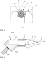
- Figure 3 shows the tip portion 14 of the sample holder 10 in a top view in more detail and with a sample carrier 13, wherein the sample carrier 13 comprises a copper-grid 50 containing nanoparticles as a sample 12.
- the seat 16 fixes the sample 12 or the sample carrier 13 in a form-locking manner in all but one directions.
- the movable or rotatable element 22 of the sample holder 10 is in a loading position of Figure 2 , thus the element 22 is turned away from the seat 16.
- the sample 12 or the sample carrier 13 may be placed into the seat 16 from above and is fixed by the seat 16 in a form-locked manner in all but the upward direction. This prevents the sample 12 or the sample carrier 13 from gliding of the sample holder 10.
- the element 22 is turned towards the seat 16. This may be done by actuating the handle 26 into the closed position as shown in Figure 1 .
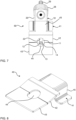
- Figures 4 to 7 show schematic drawings of the measurement system 50 of the invention according to an embodiment in different perspectives. Particularly, Figure 4 shows a side view of the measurement system 50, Figures 5 and 6 show perspective bottom and top views of the measurement system 50, respectively, and Figure 7 shows a plan view thereof.
- the measurement system 50 comprises the sample holder 10 as described in detail with respect to Figures 1 to 3 .
- the measurement system 50 further comprises the aperture extension 40, a schematic drawing of a perspective top view of which is shown in Figure 8 .
- the aperture extension 40 as shown in Figure 8 is a monolithic metal piece made from an Al-Mg-alloy, which is the same material as that of the sample holder 10.
- the aperture extension 40 comprises an attachment portion 41 that comprises a bent metal bar, a section thereof forming a U-shaped metal bar 45. Further, two handle portions protrude outwardly from the side legs of the U-shaped metal bar 45 and are configured to simplify the handling of the attachment portion 41 and thus of the whole aperture extension 40.
- the opening width i.e., the distance between the side legs of the U-shape or the extension of the inner leg connecting the side legs, is adapted to the size of the main body 20 of the sample holder 10.
- the aperture extension 40 is adapted to be mounted to the main body 20 of the sample holder 10 via a force and/or form closure as described with respect to Figures 4 to 7 .
- the attachment portion 41 is monolithically formed with a joint portion 42 that is angled with respect to the attachment portion 41, particularly with respect to the inner leg of the attachment portion 41.
- the joint portion 42 comprises a first sub-portion that is plane-parallel to the inner leg of the attachment portion 41 that extends continuously into a second sub-portion that is angled with respect to the attachment portion 41, particularly with respect to the inner leg of the attachment portion 41.
- the angle between the joint portion 42 and the attachment portion 41, particularly between the second sub-portion of the joint portion 42 and the attachment portion 41 is identical to the angle of the tapered portion 11 of the sample holder 10, particularly with respect to the remaining main body 20 of the sample holder 10 in between tapered portion 11 and connecting member 28. This allows the joint portion 42 to fit closely to the tapered portion 11 as the aperture extension 40 is mounted to the sample holder 10 as described with respect to Figures 4 to 7 .
- the joint portion 42 is formed monolithically with an aperture portion 43 that is angled with respect to the joint portion 42, at least with respect to the second sub-section of the joint portion 42.
- the aperture portion 43 may have the same width as the joint portion 42.
- the aperture portion 43 is preferably oriented parallely to the contact plane 18 of sample holder 10.
- the aperture portion 43 comprises an aperture opening 44, i.e., a through hole, that extends also into the joint portion 42.
- the aperture opening 44 is positioned above the sample 12, if the aperture extension 40 is mounted in a working position to the sample holder 10 as it is shown in Figure 7 and described with respect to Figures 4 to 7 .
- the aperture extension 40 is mounted to the sample holder 10 such that the aperture extension 40 is in its mounting position.
- the attachment portion 41 is slid over the main body 20 of the sample holder 10 in between the tapered portion 11 and the screw 30 such that the side legs of the U-shaped metal bar 45 are closely fitted to the side walls of the main body 20 and such that the inner leg of the U-shaped metal bar 45 is closely fitted to the top surface of the main body 20.
- the U-shaped metal bar 45 is attached to the main body 20 via a form closure and a force closure.
- the first sub-section of the joint portion 42 extends over the main body 20 until the point where it begins to narrow, i.e., to the beginning of the tapered portion 11 of the sample holder 10.
- the second sub-portion of the joint portion 42 starts, the shape of which is adapted to the shape of the tapered portion 11.
- the joint portion 42 fits closely to the tapered portion 11, wherein a distance between the joint portion 42 and the tapered portion 11 remains constantly small.
- the joint portion 42 is mounted directly to the sample holder 10, i.e., without any distance between the first sub-section and the main body 20 and second sub-section and the tapered portion 11.
- the aperture opening 44 is disposed above the sample 12 and extends laterally and omnidirectional over the sample 12. Particularly, the sample 12 is positioned central within the aperture opening 44 in a plan view onto the sample 12. The aperture opening 44 thus extends into the joint portion 42 due to the size of the aperture opening 44.
- the diameter of the aperture opening 44 is advantageously reduced and hence its performance in blocking stray X-rays, while letting pass characteristic X-rays emitted from sample 12 is improved. This is described in more detail with respect to Figures 9 and 10 .
- Figures 9 and 10 illustrate combined EDS and TKD measurement systems mounted to an electron microscope 60, wherein Figure 9 denotes a system according to the prior art wherein Figure 10 denotes a system 50 according to an embodiment of the present invention.
- an electron microscope, EM, 60 which is a scanning electron microscope (SEM), is configured to perform transmission Kikuchi diffraction (TKD) measurements.
- a pole piece 62 which is part of an electron lens 61 of the EM 60 is arranged at a column of the EM 60.
- the EM 60 comprises the sample holder 10 and a TKD detector 64, which comprises a phosphor screen 65.
- the EM 60 comprises an EDS (energy dispersive X-ray spectroscopy) detector 67.
- the EM 60 is configured to perform EDS measurements with the EDS detector 67 and to perform TKD measurements with the TKD detector 64.
- the sample 12 or the sample carrier 13, the column comprising the electron lenses 61 with the pole piece 62, the TKD detector 64 and the EDS detector 67 are arranged in a way, such that TKD measurements and EDS measurements can be made without changing the position of the sample holder 10, the column comprising the electron lenses 61 with the pole piece 62, the TKD detector 64 or the EDS detector 67.
- an electron microscope 60 comprises a sample holder 10 as described above.
- the sample holder 10 is positioned between the EDS detector 67 and the TKD detector 64 such that a sample 12 loaded to the sample holder 10 is positioned between an active area 68 of the EDS detector 67 and a phosphor screen 65 of the TKD detector 64.
- the sample 12 is positioned between the EDS detector 67 and the TKD detector 64 with respect to the propagation direction of an electron beam 80, emitted by the electron microscope 60, particularly from a pole piece 62 of the EM 60, and focussed by a magnetic lens 61.
- the active area 68 of the EDS detector 67 is plane-parallel to the contact area 18 defined by the sample 12 loaded to the sample holder 10.
- the phosphor screen 65 of the TKD detector 64 is plane-parallel to the contact plane 18.
- the contact plane 18 is considered to contain the sample 12 and to extend laterally over the sample 12. With respect to such contact plane 18, preferably the normal directions of the contact plane 18, the active area 68 and the phosphor screen 65 are parallel to each other.
- the sample 12 is prepared electron transparent such that at least part of the incident electron beam 80 is transmitted through the sample 12 and positioned such that the primary electron beam 80 is incident on the sample 12.
- the incident primary electrons are traversing the sample 12 and hence diffracted electrons 82 exit the sample 12 via an exit surface thereof facing the phosphor screen 65 of the TKD detector 64.
- These transmitted and diffracted electrons 82 allow for detecting Kikuchi patterns of the sample 12 via the TKD detector 64.
- the incident primary electron beam 80 effects the generation of characteristic X-rays of the sample 12.
- the characteristic X-rays exiting the sample 12 via a top surface propagate towards the active area 68 of EDS detector 67, thus allowing for obtaining EDS spectra from the sample 12 and performing an element composition analysis on the sample 12.
- sample 12 and detectors 64, 67 as illustrated in Figure 9 advantageously enables simultaneous acquisition of Kikuchi patterns and EDS spectra at speeds, which can be at least one order of magnitude faster than with conventional detectors, using the same electron beam parameters.
- the main factor limiting the acquisition speed in combined TKD/EDS measurements is the reduced X-Ray signal resulting from the interaction of the incident beam 80 with the electron transparent sample 12 within a very small interaction volume.
- the EDS detector 67 that is positioned underneath the pole piece 67 and right above the electron transparent sample 12 it is advantageously possible to increase the X-ray capturing solid angle by up to two orders of magnitude and hence to increase the X-ray input count rate in a corresponding manner.
- the much higher X-Ray input/output count rate enables fast measurements without affecting the signal to noise ratio in the EDS spectra.
- the transmitted and diffracted electrons 82 exiting the sample 12 towards the TKD detector 64 will inevitably hit the phosphor screen 65 of the TKD detector 64, where they can also effect the generation of characteristic X-rays 81 of the phosphor screen 65.
- These characteristic X-rays 81 can also propagate upwards towards sample 12 and, if they bypass the sample 12, can reach the active area 68 of the EDS detector 67 as stray X-rays.
- stray X-rays are deleterious to the measurement in two ways: first they are producing "stray" peaks in the EDS spectrum which can interfere with the processing/quantification process and, second, they significantly increase the input count rate and therefore could limit the output count rate of the EDS detector 67 thus reducing the amount of useful counts originating from the sample 12 with a direct influence on the SNR or quality of the EDS spectrum.
- the aperture extension 40 as shown in Figure 8 was developed for the sample holder 10 of Figures 1 to 2 in order to generate the measurement system 50 as shown in Figures 4 to7.
- the special design of the aperture extension 40 allows it to fit and to be easily fixed and removed onto or from the sample holder 10, respectively.
- the aperture extension 40 is further made of the same material as the sample holder 10 in order to avoid the production of additional peaks that could show up in any EDS spectrum. Further, the aperture extension 40, once mounted to its working position onto the sample holder 10, has the function of physically blocking stray X-rays originating from the phosphor screen 65.
- Figure 10 shows the measurement system 50 of the invention mounted to the EM 60.
- the primary electron beam 80 can reach the sample 12 through the aperture opening 44 of the aperture portion 43 of the aperture extension 40.
- the diffraction of the incident electron beam 80 and the generation of characteristic X-rays 81 can occur in the sample 12 as described above with respect to Figure 9 .
- the transmitted and diffracted electrons 82 With respect to the transmitted and diffracted electrons 82, the situation remains unchanged by the aperture extension 40 mounted between the sample 12 and the EDS detector 64 and they exit the sample 12 towards the TKD detector 64, where they enable the measurement of Kikuchi patterns and effect the generation of characteristic X-rays 81 of the phosphor screen 65.
- the aperture extension 40 particularly the aperture portion 43 and the joint portion 42, preferably extends such that any straight line connecting any point of the phosphor screen 65 with any point of the active area 68 of the EDS detector 67 will cross the aperture extension 40, particularly the aperture portion 43 or the joint portion 42.
- the size of the aperture extension 40 has to be adapted with respect to the size of the phosphor screen 65, the active area 68 and the mounting position of the sample holder 10 along the z-axis.
- the required calculations for determining the size, particularly the lateral extension of the aperture extension, are straight-forward and can be carried out by the skilled person.
- the majority of X-rays produced by the phosphor screen 65 below the sample 12 are blocked by the aperture extension 40 and hence the EDS spectra are improved.
- the aperture extension 40 features the, preferably circular, aperture opening 44 that is positioned right above the electron transparent sample 12, any characteristic X-rays 81 generated by the sample 12 itself, can still reach the active area 68 of the EDS detector 67 and thus EDS measurements are not impeded by the aperture extension 40.
- the aperture extension's 40 shape was designed so that the joint portion 42 fits closely to the slope of the sample holder's 10 tapered portion 11, the aperture extension 40, particularly the joint portion 42, can be placed as close as possible to the sample 12. This advantageously allows reducing the size of the aperture opening 44 without affecting the capturing solid angle of the characteristic X-rays 81 produced by the sample 12.
- the aperture extension 40 of the invention being adapted to the shape of the sample holder 10 advantageously allows for reducing the amount of stray X-rays reaching EDS detector 67.
Landscapes
- Chemical & Material Sciences (AREA)
- Analytical Chemistry (AREA)
- Physics & Mathematics (AREA)
- Health & Medical Sciences (AREA)
- Life Sciences & Earth Sciences (AREA)
- Biochemistry (AREA)
- General Health & Medical Sciences (AREA)
- General Physics & Mathematics (AREA)
- Immunology (AREA)
- Pathology (AREA)
- Crystallography & Structural Chemistry (AREA)
- Analysing Materials By The Use Of Radiation (AREA)
Claims (13)
- Messsystem (50) zur kombinierten energiedispersiven-Spektroskopie-, EDS-, und Transmissions-Kikuchi-Beugungs-, TKD-, Messung, umfassend:einen Probenhalter (10) zum Positionieren einer Probe (12) in einem Elektronenmikroskop, EM, (60), wobei der Probenhalter (10) einen Hauptkörper (20) mit einem sich verjüngenden Abschnitt (11) aufweist, der in einem Spitzenabschnitt (14) endet, der dazu ausgestaltet ist, die Probe (12) derart aufzunehmen, dass die Probe (12) auf einer Kontaktebene (18) angeordnet ist; undeine Aperturerweiterung (40) miteinem Anbringungsabschnitt (41), der einen U-förmigen Metallstab (45) umfasst und mit dem Hauptkörper (20) außerhalb des sich verjüngenden Abschnitts (11) und des Spitzenabschnitts (14) dadurch mechanisch in Eingriff steht, dass Seitenfüße des U-förmigen Metallstabs (45) nah an Seitenwänden des Hauptkörpers (20) befestigt sind und ein Innenfuß des U-förmigen Metallstabs (45) nah an einer oberen Oberfläche des Hauptkörpers (20) befestigt ist, wobei der Anbringungsabschnitt (41) dazu ausgestaltet ist, die Aperturerweiterung (40) an dem Probenhalter (10) zu fixieren;einem Aperturabschnitt (43), der sich lateral über den Spitzenabschnitt (14) in einer Ebene, die planparallel zu der Kontaktebene (18) verläuft, erstreckt und den Spitzenabschnitt (14) überlappt, wobei eine Erweiterung des Aperturabschnitts (43) parallel zu der Kontaktebene (18) größer als eine Erweiterung des Spitzenabschnitts (14) parallel zu der Kontaktebene (18) ist; undeine an dem Aperturabschnitt (43) angeordnete Aperturöffnung (44), die eine Erweiterung parallel zu der Kontaktebene (18), die größer als die Erweiterung der Probe (12) parallel zu der Kontaktebene (18) ist, aufweist und die Probe (12) überlappt.
- Messsystem (50) nach Anspruch 1, wobei die Aperturerweiterung (40) einen Verbindungsabschnitt (42) umfasst, der den Anbringungsabschnitt (41) und den Aperturabschnitt (43) verbindet, und wobei der Verbindungsabschnitt (42) an die Form des sich verjüngenden Abschnitts (11) angepasst ist.
- Messsystem (50) nach Anspruch 2, wobei sich die Aperturöffnung (44) in den Verbindungsabschnitt (42) erstreckt.
- Messsystem (50) nach Anspruch 2 oder 3, wobei der Verbindungsabschnitt (42) nah an dem sich verjüngenden Abschnitt (11) befestigt ist.
- Messsystem (50) nach einem der vorstehenden Ansprüche, wobei sich die Aperturöffnung (44) lateral über die Probe (12) erstreckt.
- Messsystem (50) nach einem der vorstehenden Ansprüche, wobei sich der Aperturabschnitt (43) omnidirektional über den Spitzenabschnitt (14) erstreckt.
- Messsystem (50) nach einem der vorstehenden Ansprüche, wobei der Probenhalter (10) ferner ein bewegliches oder drehbares Element (22) umfasst, das dazu ausgestaltet ist, die Probe (12) an dem Spitzenabschnitt (14) in einer ersten Position des Elements (22) zu fixieren und die Probe (12) in einer zweiten Position des Elements (22) aufzunehmen und abzugeben, und wobei der Anbringungsabschnitt (41) dazu ausgestaltet ist, mit dem Hauptkörper (20) in der ersten Position des Elements (22) mechanisch in Eingriff zu stehen.
- Messsystem (50) nach einem der vorstehenden Ansprüche, wobei der Probenhalter (10) und die Aperturerweiterung (40) aus dem gleichen Material sind.
- Messsystem (50) nach einem der vorstehenden Ansprüche, wobei der Probenhalter (10) ferner ein Verbindungselement (28) umfasst, das sich von einer Seite des Hauptkörpers (20) gegenüber einer Seite des sich verjüngenden Abschnitts (11) erstreckt und einen Stiftstumpf (29) umfasst, der dazu ausgestaltet ist, in einen Tisch (66) des EM (60) gesteckt zu werden.
- Messsystem (50) nach einem der vorstehenden Ansprüche, ferner umfassend ein Elektronenmikroskop, EM, (60) einen EDS-Detektor (67) und einen TKD-Detektor (64), wobei das EM (60) dazu ausgestaltet ist, EDS-Messungen mit dem EDS-Detektor (67) durchzuführen und TKD-Messungen mit dem TKD-Detektor (64) durchzuführen, und wobei die Aperturerweiterung (40) an dem Probenhalter (10) in einer Arbeitsposition zwischen dem Probenhalter (10) und einem von dem EDS- (67) und dem TKD-Detektor (64) fixiert ist, sodass die Aperturöffnung (44) zwischen der Probe (12) und dem einen von dem EDS- (67) und dem TKD-Detektor (64) positioniert ist.
- Messsystem (50) nach Anspruch 10, wobei der Aperturabschnitt (43) dazu ausgestaltet ist, Röntgenstrahlen (81) zu blockieren, die sich von einem Phosphorschirm (65) des TKD-Detektors (64) in Richtung des EDS-Detektors (67) ausbreiten.
- Messsystem (50) nach Anspruch 10 oder 11, wobei die Aperturöffnung (44) zum Durchlassen von Strahlung, die sich von der Probe (12) in Richtung des einen von dem EDS- (67) und dem TKD-Detektor (64) ausbreitet, ausgestaltet ist.
- Messsystem (50) nach einem der Ansprüche 10 bis 12, wobei der EDS-Detektor (67) über einer ersten Seite der Kontaktebene (18) angeordnet ist und wobei der TKD-Detektor (64) unter einer zweiten Seite der Kontaktebene (18) gegenüber der ersten Seite angeordnet ist.
Priority Applications (1)
| Application Number | Priority Date | Filing Date | Title |
|---|---|---|---|
| EP19163044.1A EP3709008B1 (de) | 2019-03-15 | 2019-03-15 | Messsystem zur messung von eds/tkd |
Applications Claiming Priority (1)
| Application Number | Priority Date | Filing Date | Title |
|---|---|---|---|
| EP19163044.1A EP3709008B1 (de) | 2019-03-15 | 2019-03-15 | Messsystem zur messung von eds/tkd |
Publications (2)
| Publication Number | Publication Date |
|---|---|
| EP3709008A1 EP3709008A1 (de) | 2020-09-16 |
| EP3709008B1 true EP3709008B1 (de) | 2024-07-17 |
Family
ID=66048983
Family Applications (1)
| Application Number | Title | Priority Date | Filing Date |
|---|---|---|---|
| EP19163044.1A Active EP3709008B1 (de) | 2019-03-15 | 2019-03-15 | Messsystem zur messung von eds/tkd |
Country Status (1)
| Country | Link |
|---|---|
| EP (1) | EP3709008B1 (de) |
Families Citing this family (3)
| Publication number | Priority date | Publication date | Assignee | Title |
|---|---|---|---|---|
| CN112782198B (zh) * | 2020-12-07 | 2023-02-10 | 上海大学 | 多设备联用的三维原子探针样品通用接口装置 |
| CN115128109B (zh) * | 2022-09-02 | 2022-11-25 | 北京化工大学 | 基于取向标定校正的ebsd样品台及图像获取方法 |
| CN116242867B (zh) * | 2023-02-14 | 2025-08-01 | 集萃新材料研发有限公司 | 一种实现fib-tkd联用的样品夹具及扫描电镜检测系统 |
Family Cites Families (2)
| Publication number | Priority date | Publication date | Assignee | Title |
|---|---|---|---|---|
| EP2824448B1 (de) | 2013-07-08 | 2016-12-14 | Bruker Nano GmbH | Probenhalter für Elektronenrückstreuungsbeugung |
| JP6962721B2 (ja) * | 2017-06-23 | 2021-11-05 | 日本電子株式会社 | 試料ホルダーおよび電子顕微鏡 |
-
2019
- 2019-03-15 EP EP19163044.1A patent/EP3709008B1/de active Active
Also Published As
| Publication number | Publication date |
|---|---|
| EP3709008A1 (de) | 2020-09-16 |
Similar Documents
| Publication | Publication Date | Title |
|---|---|---|
| EP3709008B1 (de) | Messsystem zur messung von eds/tkd | |
| EP2824448B1 (de) | Probenhalter für Elektronenrückstreuungsbeugung | |
| US6627889B2 (en) | Apparatus and method for observing sample using electron beam | |
| JP5801891B2 (ja) | 電子イメージングを用いて試料の画像を作成する荷電粒子線装置及び方法 | |
| EP3770945B1 (de) | Detektor von kikuchi-beugung | |
| US7755043B1 (en) | Bright-field/dark-field detector with integrated electron energy spectrometer | |
| CN110455833B (zh) | 电子显微镜中的eels检测技术 | |
| JP7030549B2 (ja) | 荷電粒子源の放出雑音補正 | |
| Rose et al. | XTIP–the world's first beamline dedicated to the synchrotron X-ray scanning tunneling microscopy technique | |
| US20030230713A1 (en) | Raster electron microscope | |
| EP3489989B1 (de) | Ladungsträgerteilchenmikroskop mit einstellbarer strahlenergiespreizung | |
| JP2024022573A (ja) | 試料ホルダクランプ | |
| JP7245885B2 (ja) | X線検出装置及び方法 | |
| US20120292508A1 (en) | X-Ray Detection System | |
| Gubbens et al. | An imaging filter for high voltage electron microscopy | |
| JP2019102464A (ja) | 改善されたeels/eftemモジュールを有する透過型荷電粒子顕微鏡 | |
| JP7615499B2 (ja) | 荷電粒子ビームのエネルギー幅を決定する方法 | |
| US10504690B2 (en) | Sample holder and electron microscope | |
| US10529530B2 (en) | Charged particle beam system | |
| JP2011129343A (ja) | 荷電粒子線装置の試料ホルダ | |
| US11699567B2 (en) | X-ray detection apparatus and method | |
| JP7416254B2 (ja) | 蛍光x線分析装置 | |
| JP2022074749A (ja) | X線検出器および荷電粒子線装置 | |
| JPH0119081Y2 (de) | ||
| Yasufuku et al. | On the wide-energy-range tuning of x-ray photoemission electron microscope optics for the observation of the photoelectrons excited by several keV x-rays |
Legal Events
| Date | Code | Title | Description |
|---|---|---|---|
| PUAI | Public reference made under article 153(3) epc to a published international application that has entered the european phase |
Free format text: ORIGINAL CODE: 0009012 |
|
| STAA | Information on the status of an ep patent application or granted ep patent |
Free format text: STATUS: REQUEST FOR EXAMINATION WAS MADE |
|
| 17P | Request for examination filed |
Effective date: 20200319 |
|
| AK | Designated contracting states |
Kind code of ref document: A1 Designated state(s): AL AT BE BG CH CY CZ DE DK EE ES FI FR GB GR HR HU IE IS IT LI LT LU LV MC MK MT NL NO PL PT RO RS SE SI SK SM TR |
|
| AX | Request for extension of the european patent |
Extension state: BA ME |
|
| STAA | Information on the status of an ep patent application or granted ep patent |
Free format text: STATUS: EXAMINATION IS IN PROGRESS |
|
| 17Q | First examination report despatched |
Effective date: 20220428 |
|
| GRAP | Despatch of communication of intention to grant a patent |
Free format text: ORIGINAL CODE: EPIDOSNIGR1 |
|
| STAA | Information on the status of an ep patent application or granted ep patent |
Free format text: STATUS: GRANT OF PATENT IS INTENDED |
|
| INTG | Intention to grant announced |
Effective date: 20240209 |
|
| GRAS | Grant fee paid |
Free format text: ORIGINAL CODE: EPIDOSNIGR3 |
|
| GRAA | (expected) grant |
Free format text: ORIGINAL CODE: 0009210 |
|
| STAA | Information on the status of an ep patent application or granted ep patent |
Free format text: STATUS: THE PATENT HAS BEEN GRANTED |
|
| AK | Designated contracting states |
Kind code of ref document: B1 Designated state(s): AL AT BE BG CH CY CZ DE DK EE ES FI FR GB GR HR HU IE IS IT LI LT LU LV MC MK MT NL NO PL PT RO RS SE SI SK SM TR |
|
| REG | Reference to a national code |
Ref country code: CH Ref legal event code: EP |
|
| REG | Reference to a national code |
Ref country code: DE Ref legal event code: R096 Ref document number: 602019055251 Country of ref document: DE |
|
| P01 | Opt-out of the competence of the unified patent court (upc) registered |
Free format text: CASE NUMBER: APP_40784/2024 Effective date: 20240710 |
|
| REG | Reference to a national code |
Ref country code: IE Ref legal event code: FG4D |
|
| REG | Reference to a national code |
Ref country code: LT Ref legal event code: MG9D |
|
| REG | Reference to a national code |
Ref country code: NL Ref legal event code: MP Effective date: 20240717 |
|
| PG25 | Lapsed in a contracting state [announced via postgrant information from national office to epo] |
Ref country code: PT Free format text: LAPSE BECAUSE OF FAILURE TO SUBMIT A TRANSLATION OF THE DESCRIPTION OR TO PAY THE FEE WITHIN THE PRESCRIBED TIME-LIMIT Effective date: 20241118 |
|
| REG | Reference to a national code |
Ref country code: AT Ref legal event code: MK05 Ref document number: 1704588 Country of ref document: AT Kind code of ref document: T Effective date: 20240717 |
|
| PG25 | Lapsed in a contracting state [announced via postgrant information from national office to epo] |
Ref country code: NL Free format text: LAPSE BECAUSE OF FAILURE TO SUBMIT A TRANSLATION OF THE DESCRIPTION OR TO PAY THE FEE WITHIN THE PRESCRIBED TIME-LIMIT Effective date: 20240717 |
|
| PG25 | Lapsed in a contracting state [announced via postgrant information from national office to epo] |
Ref country code: PT Free format text: LAPSE BECAUSE OF FAILURE TO SUBMIT A TRANSLATION OF THE DESCRIPTION OR TO PAY THE FEE WITHIN THE PRESCRIBED TIME-LIMIT Effective date: 20241118 Ref country code: NL Free format text: LAPSE BECAUSE OF FAILURE TO SUBMIT A TRANSLATION OF THE DESCRIPTION OR TO PAY THE FEE WITHIN THE PRESCRIBED TIME-LIMIT Effective date: 20240717 |
|
| PG25 | Lapsed in a contracting state [announced via postgrant information from national office to epo] |
Ref country code: NO Free format text: LAPSE BECAUSE OF FAILURE TO SUBMIT A TRANSLATION OF THE DESCRIPTION OR TO PAY THE FEE WITHIN THE PRESCRIBED TIME-LIMIT Effective date: 20241017 |
|
| PG25 | Lapsed in a contracting state [announced via postgrant information from national office to epo] |
Ref country code: GR Free format text: LAPSE BECAUSE OF FAILURE TO SUBMIT A TRANSLATION OF THE DESCRIPTION OR TO PAY THE FEE WITHIN THE PRESCRIBED TIME-LIMIT Effective date: 20241018 Ref country code: FI Free format text: LAPSE BECAUSE OF FAILURE TO SUBMIT A TRANSLATION OF THE DESCRIPTION OR TO PAY THE FEE WITHIN THE PRESCRIBED TIME-LIMIT Effective date: 20240717 Ref country code: PL Free format text: LAPSE BECAUSE OF FAILURE TO SUBMIT A TRANSLATION OF THE DESCRIPTION OR TO PAY THE FEE WITHIN THE PRESCRIBED TIME-LIMIT Effective date: 20240717 |
|
| PG25 | Lapsed in a contracting state [announced via postgrant information from national office to epo] |
Ref country code: BG Free format text: LAPSE BECAUSE OF FAILURE TO SUBMIT A TRANSLATION OF THE DESCRIPTION OR TO PAY THE FEE WITHIN THE PRESCRIBED TIME-LIMIT Effective date: 20240717 |
|
| PG25 | Lapsed in a contracting state [announced via postgrant information from national office to epo] |
Ref country code: LV Free format text: LAPSE BECAUSE OF FAILURE TO SUBMIT A TRANSLATION OF THE DESCRIPTION OR TO PAY THE FEE WITHIN THE PRESCRIBED TIME-LIMIT Effective date: 20240717 |
|
| PG25 | Lapsed in a contracting state [announced via postgrant information from national office to epo] |
Ref country code: IS Free format text: LAPSE BECAUSE OF FAILURE TO SUBMIT A TRANSLATION OF THE DESCRIPTION OR TO PAY THE FEE WITHIN THE PRESCRIBED TIME-LIMIT Effective date: 20241117 Ref country code: AT Free format text: LAPSE BECAUSE OF FAILURE TO SUBMIT A TRANSLATION OF THE DESCRIPTION OR TO PAY THE FEE WITHIN THE PRESCRIBED TIME-LIMIT Effective date: 20240717 |
|
| PG25 | Lapsed in a contracting state [announced via postgrant information from national office to epo] |
Ref country code: HR Free format text: LAPSE BECAUSE OF FAILURE TO SUBMIT A TRANSLATION OF THE DESCRIPTION OR TO PAY THE FEE WITHIN THE PRESCRIBED TIME-LIMIT Effective date: 20240717 |
|
| PG25 | Lapsed in a contracting state [announced via postgrant information from national office to epo] |
Ref country code: RS Free format text: LAPSE BECAUSE OF FAILURE TO SUBMIT A TRANSLATION OF THE DESCRIPTION OR TO PAY THE FEE WITHIN THE PRESCRIBED TIME-LIMIT Effective date: 20241017 Ref country code: ES Free format text: LAPSE BECAUSE OF FAILURE TO SUBMIT A TRANSLATION OF THE DESCRIPTION OR TO PAY THE FEE WITHIN THE PRESCRIBED TIME-LIMIT Effective date: 20240717 |
|
| PG25 | Lapsed in a contracting state [announced via postgrant information from national office to epo] |
Ref country code: RS Free format text: LAPSE BECAUSE OF FAILURE TO SUBMIT A TRANSLATION OF THE DESCRIPTION OR TO PAY THE FEE WITHIN THE PRESCRIBED TIME-LIMIT Effective date: 20241017 Ref country code: PL Free format text: LAPSE BECAUSE OF FAILURE TO SUBMIT A TRANSLATION OF THE DESCRIPTION OR TO PAY THE FEE WITHIN THE PRESCRIBED TIME-LIMIT Effective date: 20240717 Ref country code: NO Free format text: LAPSE BECAUSE OF FAILURE TO SUBMIT A TRANSLATION OF THE DESCRIPTION OR TO PAY THE FEE WITHIN THE PRESCRIBED TIME-LIMIT Effective date: 20241017 Ref country code: LV Free format text: LAPSE BECAUSE OF FAILURE TO SUBMIT A TRANSLATION OF THE DESCRIPTION OR TO PAY THE FEE WITHIN THE PRESCRIBED TIME-LIMIT Effective date: 20240717 Ref country code: IS Free format text: LAPSE BECAUSE OF FAILURE TO SUBMIT A TRANSLATION OF THE DESCRIPTION OR TO PAY THE FEE WITHIN THE PRESCRIBED TIME-LIMIT Effective date: 20241117 Ref country code: HR Free format text: LAPSE BECAUSE OF FAILURE TO SUBMIT A TRANSLATION OF THE DESCRIPTION OR TO PAY THE FEE WITHIN THE PRESCRIBED TIME-LIMIT Effective date: 20240717 Ref country code: GR Free format text: LAPSE BECAUSE OF FAILURE TO SUBMIT A TRANSLATION OF THE DESCRIPTION OR TO PAY THE FEE WITHIN THE PRESCRIBED TIME-LIMIT Effective date: 20241018 Ref country code: FI Free format text: LAPSE BECAUSE OF FAILURE TO SUBMIT A TRANSLATION OF THE DESCRIPTION OR TO PAY THE FEE WITHIN THE PRESCRIBED TIME-LIMIT Effective date: 20240717 Ref country code: ES Free format text: LAPSE BECAUSE OF FAILURE TO SUBMIT A TRANSLATION OF THE DESCRIPTION OR TO PAY THE FEE WITHIN THE PRESCRIBED TIME-LIMIT Effective date: 20240717 Ref country code: BG Free format text: LAPSE BECAUSE OF FAILURE TO SUBMIT A TRANSLATION OF THE DESCRIPTION OR TO PAY THE FEE WITHIN THE PRESCRIBED TIME-LIMIT Effective date: 20240717 Ref country code: AT Free format text: LAPSE BECAUSE OF FAILURE TO SUBMIT A TRANSLATION OF THE DESCRIPTION OR TO PAY THE FEE WITHIN THE PRESCRIBED TIME-LIMIT Effective date: 20240717 |
|
| PGFP | Annual fee paid to national office [announced via postgrant information from national office to epo] |
Ref country code: DE Payment date: 20250320 Year of fee payment: 7 |
|
| PG25 | Lapsed in a contracting state [announced via postgrant information from national office to epo] |
Ref country code: DK Free format text: LAPSE BECAUSE OF FAILURE TO SUBMIT A TRANSLATION OF THE DESCRIPTION OR TO PAY THE FEE WITHIN THE PRESCRIBED TIME-LIMIT Effective date: 20240717 Ref country code: SM Free format text: LAPSE BECAUSE OF FAILURE TO SUBMIT A TRANSLATION OF THE DESCRIPTION OR TO PAY THE FEE WITHIN THE PRESCRIBED TIME-LIMIT Effective date: 20240717 Ref country code: RO Free format text: LAPSE BECAUSE OF FAILURE TO SUBMIT A TRANSLATION OF THE DESCRIPTION OR TO PAY THE FEE WITHIN THE PRESCRIBED TIME-LIMIT Effective date: 20240717 |
|
| REG | Reference to a national code |
Ref country code: DE Ref legal event code: R097 Ref document number: 602019055251 Country of ref document: DE |
|
| PG25 | Lapsed in a contracting state [announced via postgrant information from national office to epo] |
Ref country code: EE Free format text: LAPSE BECAUSE OF FAILURE TO SUBMIT A TRANSLATION OF THE DESCRIPTION OR TO PAY THE FEE WITHIN THE PRESCRIBED TIME-LIMIT Effective date: 20240717 |
|
| PG25 | Lapsed in a contracting state [announced via postgrant information from national office to epo] |
Ref country code: CZ Free format text: LAPSE BECAUSE OF FAILURE TO SUBMIT A TRANSLATION OF THE DESCRIPTION OR TO PAY THE FEE WITHIN THE PRESCRIBED TIME-LIMIT Effective date: 20240717 |
|
| PG25 | Lapsed in a contracting state [announced via postgrant information from national office to epo] |
Ref country code: SK Free format text: LAPSE BECAUSE OF FAILURE TO SUBMIT A TRANSLATION OF THE DESCRIPTION OR TO PAY THE FEE WITHIN THE PRESCRIBED TIME-LIMIT Effective date: 20240717 |
|
| PGFP | Annual fee paid to national office [announced via postgrant information from national office to epo] |
Ref country code: GB Payment date: 20250324 Year of fee payment: 7 |
|
| PLBE | No opposition filed within time limit |
Free format text: ORIGINAL CODE: 0009261 |
|
| STAA | Information on the status of an ep patent application or granted ep patent |
Free format text: STATUS: NO OPPOSITION FILED WITHIN TIME LIMIT |
|
| 26N | No opposition filed |
Effective date: 20250422 |
|
| PG25 | Lapsed in a contracting state [announced via postgrant information from national office to epo] |
Ref country code: SE Free format text: LAPSE BECAUSE OF FAILURE TO SUBMIT A TRANSLATION OF THE DESCRIPTION OR TO PAY THE FEE WITHIN THE PRESCRIBED TIME-LIMIT Effective date: 20240717 |
|
| PG25 | Lapsed in a contracting state [announced via postgrant information from national office to epo] |
Ref country code: MC Free format text: LAPSE BECAUSE OF FAILURE TO SUBMIT A TRANSLATION OF THE DESCRIPTION OR TO PAY THE FEE WITHIN THE PRESCRIBED TIME-LIMIT Effective date: 20240717 |
|
| REG | Reference to a national code |
Ref country code: CH Ref legal event code: H13 Free format text: ST27 STATUS EVENT CODE: U-0-0-H10-H13 (AS PROVIDED BY THE NATIONAL OFFICE) Effective date: 20251023 |
|
| PG25 | Lapsed in a contracting state [announced via postgrant information from national office to epo] |
Ref country code: LU Free format text: LAPSE BECAUSE OF NON-PAYMENT OF DUE FEES Effective date: 20250315 |
|
| REG | Reference to a national code |
Ref country code: BE Ref legal event code: MM Effective date: 20250331 |
|
| PG25 | Lapsed in a contracting state [announced via postgrant information from national office to epo] |
Ref country code: FR Free format text: LAPSE BECAUSE OF NON-PAYMENT OF DUE FEES Effective date: 20250331 |
|
| PG25 | Lapsed in a contracting state [announced via postgrant information from national office to epo] |
Ref country code: BE Free format text: LAPSE BECAUSE OF NON-PAYMENT OF DUE FEES Effective date: 20250331 |
|
| PG25 | Lapsed in a contracting state [announced via postgrant information from national office to epo] |
Ref country code: CH Free format text: LAPSE BECAUSE OF NON-PAYMENT OF DUE FEES Effective date: 20250331 |
|
| PG25 | Lapsed in a contracting state [announced via postgrant information from national office to epo] |
Ref country code: IE Free format text: LAPSE BECAUSE OF NON-PAYMENT OF DUE FEES Effective date: 20250315 |
|
| PG25 | Lapsed in a contracting state [announced via postgrant information from national office to epo] |
Ref country code: IT Free format text: LAPSE BECAUSE OF FAILURE TO SUBMIT A TRANSLATION OF THE DESCRIPTION OR TO PAY THE FEE WITHIN THE PRESCRIBED TIME-LIMIT Effective date: 20240717 |