EP3708715A1 - Baugrubenumschliessung im boden und verfahren zu deren herstellung - Google Patents
Baugrubenumschliessung im boden und verfahren zu deren herstellung Download PDFInfo
- Publication number
- EP3708715A1 EP3708715A1 EP19163092.0A EP19163092A EP3708715A1 EP 3708715 A1 EP3708715 A1 EP 3708715A1 EP 19163092 A EP19163092 A EP 19163092A EP 3708715 A1 EP3708715 A1 EP 3708715A1
- Authority
- EP
- European Patent Office
- Prior art keywords
- sealing
- groundwater
- level
- trough
- ground
- Prior art date
- Legal status (The legal status is an assumption and is not a legal conclusion. Google has not performed a legal analysis and makes no representation as to the accuracy of the status listed.)
- Granted
Links
Images



Classifications
-
- E—FIXED CONSTRUCTIONS
- E02—HYDRAULIC ENGINEERING; FOUNDATIONS; SOIL SHIFTING
- E02D—FOUNDATIONS; EXCAVATIONS; EMBANKMENTS; UNDERGROUND OR UNDERWATER STRUCTURES
- E02D19/00—Keeping dry foundation sites or other areas in the ground
-
- E—FIXED CONSTRUCTIONS
- E02—HYDRAULIC ENGINEERING; FOUNDATIONS; SOIL SHIFTING
- E02D—FOUNDATIONS; EXCAVATIONS; EMBANKMENTS; UNDERGROUND OR UNDERWATER STRUCTURES
- E02D19/00—Keeping dry foundation sites or other areas in the ground
- E02D19/06—Restraining of underground water
- E02D19/12—Restraining of underground water by damming or interrupting the passage of underground water
- E02D19/16—Restraining of underground water by damming or interrupting the passage of underground water by placing or applying sealing substances
-
- E—FIXED CONSTRUCTIONS
- E02—HYDRAULIC ENGINEERING; FOUNDATIONS; SOIL SHIFTING
- E02D—FOUNDATIONS; EXCAVATIONS; EMBANKMENTS; UNDERGROUND OR UNDERWATER STRUCTURES
- E02D31/00—Protective arrangements for foundations or foundation structures; Ground foundation measures for protecting the soil or the subsoil water, e.g. preventing or counteracting oil pollution
- E02D31/10—Protective arrangements for foundations or foundation structures; Ground foundation measures for protecting the soil or the subsoil water, e.g. preventing or counteracting oil pollution against soil pressure or hydraulic pressure
- E02D31/12—Protective arrangements for foundations or foundation structures; Ground foundation measures for protecting the soil or the subsoil water, e.g. preventing or counteracting oil pollution against soil pressure or hydraulic pressure against upward hydraulic pressure
-
- E—FIXED CONSTRUCTIONS
- E02—HYDRAULIC ENGINEERING; FOUNDATIONS; SOIL SHIFTING
- E02D—FOUNDATIONS; EXCAVATIONS; EMBANKMENTS; UNDERGROUND OR UNDERWATER STRUCTURES
- E02D19/00—Keeping dry foundation sites or other areas in the ground
- E02D19/06—Restraining of underground water
- E02D19/10—Restraining of underground water by lowering level of ground water
-
- E—FIXED CONSTRUCTIONS
- E02—HYDRAULIC ENGINEERING; FOUNDATIONS; SOIL SHIFTING
- E02D—FOUNDATIONS; EXCAVATIONS; EMBANKMENTS; UNDERGROUND OR UNDERWATER STRUCTURES
- E02D19/00—Keeping dry foundation sites or other areas in the ground
- E02D19/06—Restraining of underground water
- E02D19/12—Restraining of underground water by damming or interrupting the passage of underground water
- E02D19/18—Restraining of underground water by damming or interrupting the passage of underground water by making use of sealing aprons, e.g. diaphragms made from bituminous or clay material
Definitions
- the invention relates to a method for producing a construction pit enclosure in the ground, in which there is a groundwater level, an annular sealing wall being created in the ground, which extends from a soil surface to a predetermined depth which is below the groundwater level, and within the annular Sealing wall in a lower area below the water table, a sealing base is created by injecting a sealing medium, a sealing trough being formed in the ground by the annular sealing wall and the sealing base, according to the preamble of claim 1.
- the invention relates to a construction pit enclosure, an annular sealing wall being created in the ground, which extends from a ground surface to a predetermined depth which is below a groundwater level in the ground, and within the annular sealing wall in a lower area below the groundwater level
- the sealing base is created by injecting a sealing medium, a sealing trough being formed in the ground by the annular sealing wall and the sealing base, according to the preamble of claim 12.
- a method for producing a construction pit enclosure with an annular sealing wall and a sealing base is known below a water table.
- the sealing base is as A rigid base plate is designed, which is anchored back in deeper layers of soil using anchoring elements. Such a rigid base plate is time-consuming and costly to manufacture.
- a generic method for producing a construction pit enclosure is based on EP 2 787 123 B1 emerged.
- a sealing base is created within an annular sealing wall by injecting a sealing medium into a porous soil layer, the sealing medium forming a water-impermeable, gel-like structure in the porous soil layer.
- an overall water-impermeable soil layer and thus a sealing base is formed.
- sealing sole To achieve a desired degree of sealing of the sealing sole, it is necessary to inject a relatively large amount of sealing medium into the porous soil layer.
- an increased consumption of sealing medium is associated with an increased cost and time expenditure for introduction.
- the invention is based on the object of specifying a method for creating a construction pit enclosure in the ground and such a construction pit enclosure which enable a particularly tight construction pit enclosure with efficient use of the sealing medium.
- the method according to the invention is characterized in that groundwater from the ground within the sealing trough up to a groundwater level of a defined Compression level is pumped out which is below the groundwater level and above the sealing base, so that the groundwater in the sealing trough is kept at this compression level for a predetermined period of time, which is at least 8 hours, the sealing base being specifically compressed due to the groundwater pressure from below, and that then the groundwater level in the sealing trough is raised to an end level which is above the compression level and below the groundwater level.
- a basic idea of the invention is to specifically compress a sealing sole, which is formed by injecting a soft sealing medium into a porous soil layer, after the injection.
- the compression takes place according to the invention by hydraulic pressure from below. This is achieved by lowering the groundwater level inside the sealing trough to a certain compression level after the first raw sealing base has been created, which is below a planned end level of the groundwater level within the sealing trough when the excavation is excavated.
- the relatively high differential pressure which can preferably be between 0.5 bar and 5 bar, is set for a predetermined period of time, which is at least 8 hours. During this compaction, the soil material in the construction pit is not, at least not completely excavated, so that the sealing base is adequately supported from above against the existing water pressure from below.
- the groundwater level in the sealing trough can be raised again from the compression level to a higher final level, which is desired and sufficient for the excavation of the construction pit.
- This end level is preferably below or at least at the same level as the base of the excavation pit to be excavated.
- a preferred embodiment of the method according to the invention consists in that an excavation pit is excavated within the sealing trough, soil material being excavated up to a defined excavation bottom which is above the final level of the groundwater of the sealing trough. This ensures that no groundwater collects in the base of the excavation.
- the time span in which the groundwater level is kept at the compression level is between 8 hours and 48 hours, preferably between 12 hours and 24 hours.
- the compressed sealing base having a tightness that is up to 20% or more increased compared to the first original sealing base.
- a particularly uniform compression is achieved in that the groundwater in the sealing trough is lowered evenly over the sealing base in order to reach the compression level. This avoids larger local fluctuations in the tightness of the sealing base.
- a particularly uniform lowering of the groundwater can be achieved, in particular, by creating a plurality of wells distributed over the sealing base in order to lower the groundwater in the sealing trough, and that groundwater is pumped out of the well.
- the wells can also be designed with cross channels or as horizontal drains.
- the pumping out of the groundwater takes place over time with a variable pumping rate.
- pumping can initially take place with a reduced pumping power, which is gradually increased.
- the pump is then preferably operated with a reduced, continuous pumping power in order to maintain the set end level of the groundwater in the sealing trough.
- the pump output is set in such a way that it roughly corresponds to the inflow of groundwater.
- the pumping output is increased step by step until a desired end value is reached.
- the delivery rate per well can be 1 m 3 in the first hour, 2 m 3 in the second hour, 3 m 3 in the third hour, and so on, until a maximum value of 10 m 3 per hour and well is reached.
- this step-by-step lifting accelerates the sluggish flow behavior between the groundwater and pores in the soil layers, while at the same time preventing the flow from breaking up to the well.
- the pumping takes place differently at the individual wells.
- the pumping capacity of the individual pumps is set differently at the individual wells so that the groundwater level in the sealing trough is as evenly lowered as possible, approximately parallel to the sealing base until the final level is reached.
- the groundwater level is measured and checked during and / or after pumping out. This can be determined by appropriate measuring devices on the well.
- the individual measuring devices can preferably be wired or wirelessly connected to a central control unit, which is also wired or wirelessly connected to the pumps at the individual wells.
- the output of the individual pumps can be regulated via the control unit in order to achieve a desired lowering or maintenance of the groundwater level in the sealing trough.
- the sealing medium in principle any suitable liquid or soft sealing medium can be used with which a porous soil layer can be converted into a tight sole. It is particularly preferred that the sealing medium is a sealing gel which contains silicate, water glass and / or silica sol as components. These components can form a gel-like structure in particular with constituents in the soil or in the groundwater which a capillary system in the porous bottom layer is largely watertight.
- the annular sealing wall is designed as a bored pile wall or a diaphragm wall.
- a bored pile wall is achieved by overlapping or sticking together a large number of bored piles.
- a number of contacting or overlapping trench wall panels are created in the ground using a trench wall cutter or a trench wall gripper, which together then form a sealing or enclosing wall.
- the sealing wall can be designed in any other suitable manner, for example as a sheet pile wall or with a soil mixing process, such as a MIP® or CSM® process.
- the construction pit enclosure according to the invention is characterized in that the sealing base is specifically compacted in that the groundwater is pumped out of the ground within the sealing trough to a groundwater level of a defined compression level, which is below the groundwater level and above the sealing base, and the groundwater is in the sealing trough this compression level is maintained for a specified period of time for at least 8 hours before the groundwater level in the sealing trough is raised to a final level above the compression level after compression.
- the construction pit enclosure is produced in particular using the method according to the invention described above.
- the advantages described above can be achieved.
- FIGS. 1 to 5 illustrate the course of the production of a construction pit enclosure 10 according to the invention in a soil 5 with a given groundwater level 7.
- an annular sealing wall 12 is created in the base 5 in an initially known manner.
- the annular sealing wall 12 extends from a floor surface 6 to a provided depth in the floor 5.
- a first sealing base 14 with a rising thickness is created by injecting a sealing medium into a suitable floor layer in the floor 5.
- the sealing base 14 adjoins the inside of the enclosing sealing wall 12 tightly.
- the enclosing sealing wall 12 and the sealing base 14 thus form a sealing trough 20 in the floor 5 in a basically known manner.
- a plurality of wells 22 are drilled in the sealing trough 20, which are used to pump out the groundwater enclosed in the sealing trough 20.
- pumps (not shown) are used, which pump the groundwater out of the ground 5 and convey it to the outside of the sealing trough 20.
- the groundwater level within the sealing trough 20 is lowered from the original groundwater level 7 to a desired compression level 30.
- the compression level 30 is below the original groundwater level 7 and above the sealing base 14.
- the pumping out via the well 22 takes place in particular in such a way that the groundwater level within the sealing trough 20 is lowered as evenly as possible above the entire sealing base 14 and as parallel to it as possible.
- a differential pressure is generated at the sealing base 14 between the top and the bottom of the sealing base 14.
- a higher groundwater pressure is present on the underside of the sealing base 14, which is due to the higher groundwater level 7 compared to the lowered compression level 30 in the sealing trough 20.
- the existing water pressure is shown schematically in Fig. 2 indicated by arrows.
- this pending water pressure causes the injected sealing medium to be compressed in the bottom layer of the sealing base 14.
- This compression can be up to 10% or higher.
- the compression is brought about in particular by the fact that particles of the injected gel-like sealing medium are compressed from below by the increased differential pressure and also pressed into finer capillaries of the soil layer. In this way, a noticeable increase in the degree of tightness of the sealing base 14 is achieved.
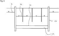
- the groundwater level within the sealing trough 20 can be increased again to a final level 32 by reducing the pumping power of the wells 22.
- This end level 32 lies above the compression level 30 and below the original groundwater level 7.
- soil material can then be excavated within the sealing trough 20 in order to form a desired construction pit 26 with a construction pit base 28.
- the excavation bottom 28 is at the same height or, as in FIG Fig. 5 shown, somewhat higher than the final level 32 of the groundwater level in the sealing trough 20.
- a construction pit enclosure 10 according to the invention is achieved with the invention, in which a particularly tight sealing base 14 is provided.
- the invention can thus reduce the amount of sealing medium to be used and, overall, create a sealing trough 20 with particularly good tightness.
Landscapes
- Engineering & Computer Science (AREA)
- Life Sciences & Earth Sciences (AREA)
- General Life Sciences & Earth Sciences (AREA)
- Mining & Mineral Resources (AREA)
- Paleontology (AREA)
- Civil Engineering (AREA)
- General Engineering & Computer Science (AREA)
- Structural Engineering (AREA)
- Environmental & Geological Engineering (AREA)
- Hydrology & Water Resources (AREA)
- Investigation Of Foundation Soil And Reinforcement Of Foundation Soil By Compacting Or Drainage (AREA)
- Bulkheads Adapted To Foundation Construction (AREA)
Abstract
Description
- Die Erfindung betrifft ein Verfahren zum Herstellen einer Baugrubenumschließung im Boden, in welchem ein Grundwasserspiegel gegeben ist, wobei im Boden eine ringförmige Dichtwand erstellt wird, welche sich von einer Bodenoberfläche bis zu einer vorgegebenen Tiefe erstreckt, welche unterhalb des Grundwasserspiegels liegt, und innerhalb der ringförmigen Dichtwand in einem unteren Bereich unterhalb des Grundwasserspiegels eine Dichtsohle durch Injizieren eines Abdichtmediums erstellt wird, wobei durch die ringförmige Dichtwand und die Dichtsohle eine Dichtwanne im Boden gebildet wird, gemäß dem Oberbegriff des Anspruchs 1.
- Des Weiteren betrifft die Erfindung eine Baugrubenumschließung, wobei im Boden eine ringförmige Dichtwand erstellt ist, welche sich von einer Bodenoberfläche bis zu einer vorgegebenen Tiefe erstreckt, welche unterhalb eines Grundwasserspiegels im Boden liegt, und innerhalb der ringförmigen Dichtwand in einem unteren Bereich unterhalb des Grundwasserspiegels eine Dichtsohle durch Injizieren eines Abdichtmediums erstellt ist, wobei durch die ringförmige Dichtwand und die Dichtsohle eine Dichtwanne im Boden gebildet ist, gemäß dem Oberbegriff des Anspruchs 12.
- Aus der
DE 196 04 525 C2 ist ein Verfahren zur Herstellung einer Baugrubenumschließung mit einer ringförmigen Dichtwand und einer Abdichtsohle unterhalb eines Grundwasserspiegels bekannt. Bei dieser Baugrubenumschließung ist die Abdichtsohle als eine starre Sohlplatte ausgeführt, welche über Rückverankerungselemente in tieferliegenden Bodenschichten rückverankert ist. Eine derartige starre Sohlplatte ist in der Herstellung zeit- und kostenaufwändig. - Ein gattungsgemäßes Verfahren zum Herstellen einer Baugrubenumschließung geht aus der
EP 2 787 123 B1 hervor. Zur Erstellung der Baugrubenumschließung wird dabei eine Dichtsohle innerhalb einer ringförmigen Dichtwand durch Injizieren eines Abdichtmediums in eine poröse Bodenschicht bewirkt, wobei das Abdichtmedium eine wasserundurchlässige, gelartige Struktur in der porösen Bodenschicht bildet. Hierdurch wird eine insgesamt wasserundurchlässige Bodenschicht und damit eine Dichtsohle gebildet. - Ein ähnliches Verfahren und eine ähnliche Baugrubenumschließung gehen auch aus der
DE 201 14 212 U1 hervor. - Zum Erzielen eines gewünschten Abdichtgrades der Abdichtsohle ist es erforderlich, eine relativ große Menge an Abdichtmedium in die poröse Bodenschicht zu injizieren. Je höher die Menge an injizierten Abdichtmedium je m2 Dichtsohle ist, umso besser die Abdichtung. Ein erhöhter Verbrauch von Abdichtmedium ist jedoch mit einem erhöhten Kosten- und Zeitaufwand zum Einbringen verbunden. Zudem ist es unter Umweltgesichtspunkten erwünscht, möglichst wenig Abdichtmedium in tieferliegende Bodenschichten zu injizieren.
- Der Erfindung liegt die Aufgabe zugrunde, ein Verfahren zum Erstellen einer Baugrubenumschließung im Boden und eine solche Baugrubenumschließung anzugeben, welche eine besonders dichte Baugrubenumschließung bei einem effizienten Einsatz des Abdichtmediums ermöglichen.
- Die Aufgabe wird zum einen durch ein Verfahren mit den Merkmalen des Anspruchs 1 und zum anderen durch eine Baugrubenumschließung mit den Merkmalen des Anspruchs 12 gelöst. Bevorzugte Ausführungsformen der Erfindung sind in den abhängigen Ansprüchen angegeben.
- Das erfindungsgemäße Verfahren ist dadurch gekennzeichnet, dass Grundwasser aus dem Boden innerhalb der Dichtwanne bis zu einem Grundwasserstand eines definierten Verdichtungsniveaus abgepumpt wird, welches unterhalb des Grundwasserspiegels und oberhalb der Dichtsohle liegt, dass das Grundwasser in der Dichtwanne auf diesem Verdichtungsniveau für eine vorgegebene Zeitspanne, welche mindestens 8 Stunden beträgt, gehalten wird, wobei die Dichtsohle aufgrund des von unten anstehenden Grundwasserdrucks gezielt verdichtet wird, und dass anschließend der Grundwasserstand in der Dichtwanne auf ein Endniveau angehoben wird, welches oberhalb des Verdichtungsniveaus und unterhalb des Grundwasserspiegels liegt.
- Eine Grundidee der Erfindung liegt darin, eine Dichtsohle, welche durch Injizieren eines weichen Abdichtmediums in eine poröse Bodenschicht gebildet ist, nach dem Injizieren gezielt zu verdichten. Das Verdichten erfolgt dabei nach der Erfindung durch einen hydraulischen Druck von unten. Dies wird dadurch erzielt, dass nach dem Erstellen der ersten Roh-Dichtsohle der Grundwasserspiegel innerhalb der Dichtwanne auf ein bestimmtes Verdichtungsniveau abgesenkt wird, welches unterhalb eines vorgesehenen Endniveaus des Grundwasserspiegels innerhalb der Dichtwanne beim Ausheben der Baugrube liegt.
- Durch dieses besonders starke Absenken des Grundwasserspiegels innerhalb der Dichtwanne auf das vorgesehene Verdichtungsniveau wird an der gebildeten ersten Dichtsohle ein relativ hoher Differenzdruck zwischen Oberseite und Unterseite erzeugt, an welcher das Grundwasser ansteht. Dieser anstehende Grundwasserdruck führt zu einer gezielten Verdichtung der Dichtsohle, da durch den anstehenden Druck die Partikel des Abdichtmediums, welche insbesondere eine gelartige Struktur bilden, so auch kleinere Kapillare in der porösen Bodenschicht zusetzen. Für eine gewünschte Verdichtung wird der relativ hohe Differenzdruck, der vorzugsweise zwischen 0,5 bar bis 5 bar betragen kann, für eine vorgegebene Zeitspanne eingestellt, welche mindestens 8 Stunden beträgt. Bei diesem Verdichten ist das Bodenmaterial in der Baugrube nicht, jedenfalls nicht vollständig ausgehoben, so dass die Dichtsohle von oben hinreichend gegen den anstehenden Wasserdruck von unten abgestützt ist.
- Nach der bewirkten Verdichtung der Dichtsohle kann der Grundwasserstand in der Dichtwanne wieder von dem Verdichtungsniveau auf ein höheres Endniveau angehoben werden, welches für das Ausheben der Baugrube gewünscht und ausreichend ist. Dieses Endniveau liegt dabei vorzugsweise unterhalb oder zumindest auf gleicher Höhe wie die Sohle der auszuhebenden Baugrube.
- Eine bevorzugte Ausführungsform des erfindungsgemäßen Verfahrens besteht darin, dass innerhalb der Dichtwanne eine Baugrube ausgehoben wird, wobei Bodenmaterial bis zu einer definierten Baugrubensohle ausgehoben wird, welche oberhalb des Endniveaus des Grundwassers der Dichtwanne liegt. Hierdurch wird sichergestellt, dass sich in der Baugrubensohle kein Grundwasser ansammelt.
- Eine besonders gute Verdichtung wird nach einer Weiterbildung der Erfindung dadurch erzielt, dass die Zeitspanne, in welcher der Grundwasserstand auf dem Verdichtungsniveau gehalten wird, zwischen 8 Stunden und 48 Stunden, vorzugsweise zwischen 12 Stunden und 24 Stunden, beträgt. In dieser Zeitspanne kann eine merkliche Erhöhung der Dichtheit der Dichtsohle erreicht werden, wobei die verdichtete Dichtsohle eine um bis zu 20% oder mehr erhöhte Dichtheit gegenüber der ersten Ursprungsdichtsohle aufweisen.
- Eine besonders gleichmäßige Verdichtung wird nach einer Verfahrensvariante dadurch erreicht, dass in der Dichtwanne das Grundwasser zum Erreichen des Verdichtungsniveaus gleichmäßig über die Dichtsohle abgesenkt wird. Hierdurch werden größere lokale Schwankungen der Dichtheit der Dichtsohle vermieden.
- Ein besonders gleichmäßiges Absenken des Grundwassers kann insbesondere dadurch erreicht werden, dass zum Absenken des Grundwassers in der Dichtwanne mehrere Brunnen verteilt über der Dichtsohle erstellt werden, und dass aus dem Brunnen Grundwasser abgepumpt wird. Je höher dabei die Anzahl der Brunnen innerhalb der Dichtwanne pro Flächeneinheit ist, umso gleichmäßiger kann das Grundwasser innerhalb der Dichtwanne auf das Verdichtungsniveau abgesenkt werden. Die Brunnen können auch mit Querkanälen oder als horizontale Drainagen (horizontal drains) ausgeführt sein.
- Dabei ist es nach einer Weiterbildung der Erfindung besonders vorteilhaft, dass das Abpumpen des Grundwassers über die Zeit mit veränderlicher Abpumpleistung erfolgt. So kann das Abpumpen zunächst mit einer reduzierten Pumpleistung erfolgen, welche allmählich gesteigert wird. Nach Erreichen des Endniveaus innerhalb der Dichtwanne wird dann vorzugsweise die Pumpe mit einer reduzierten, kontinuierlichen Pumpleistung betrieben, um das eingestellte Endniveau des Grundwassers in der Dichtwanne beizubehalten. Dabei ist zu berücksichtigen, dass eine Dichtwanne in der Praxis nie vollständig dicht ausgeführt werden kann, so dass mit einem gewissen Zustrom von Grundwasser in die Dichtwanne gerechnet werden muss. Die Pumpleistung wird dabei so eingestellt, welche in etwa dem Zustrom an Grundwasser entspricht.
- Dabei ist es besonders vorteilhaft, dass die Abpumpleistung schrittweise gesteigert wird, bis ein gewünschter Endwert erreicht ist. So kann beispielsweise die Förderleistung pro Brunnen in der ersten Stunde 1 m3 betragen, in der zweiten Stunde 2 m3, in der dritten Stunde 3 m3 usw., bis ein Maximalwert von beispielsweise 10 m3 je Stunde und Brunnen erreicht wird. Nach einer Erkenntnis der Erfindung wird durch dieses schrittweise Anheben das träge Fließverhalten zwischen Grundwasser und Poren in den Bodenschichten beschleunigt, wobei gleichzeitig ein Abriss der Strömung zum Brunnen hin verhindert wird.
- Gemäß einer weiteren Verfahrensvariante der Erfindung ist es bevorzugt, dass das Abpumpen an den einzelnen Brunnen unterschiedlich erfolgt. Dabei wird an den einzelnen Brunnen eine Abpumpleistung der einzelnen Pumpen differenziert eingestellt, so dass ein möglichst gleichmäßiges Absinken des Grundwasserniveaus in der Dichtwanne etwa parallel zur Dichtsohle bis zum Erreichen des Endniveaus bewirkt ist.
- Dabei kann es besonders vorteilhaft sein, dass der Grundwasserstand während und/oder nach dem Abpumpen gemessen und überprüft wird. Dies kann durch entsprechende Messeinrichtungen an den Brunnen ermittelt werden. Die einzelnen Messeinrichtungen können vorzugsweise drahtgebunden oder drahtlos mit einer zentralen Steuereinheit in Verbindung stehen, welche ebenfalls mit den Pumpen an den einzelnen Brunnen drahtgebunden oder drahtlos in Verbindung steht. Abhängig von den Messwerten an den einzelnen Brunnen kann über die Steuereinheit die Abpumpleistung der einzelnen Pumpen geregelt werden, um ein gewünschtes Absenken oder Halten des Grundwasserstandes in der Dichtwanne zu erreichen.
- Hinsichtlich des Abdichtmediums kann grundsätzlich jedes geeignete flüssige oder weiche Abdichtmedium verwendet werden, mit welchem eine poröse Bodenschicht in eine dichte Sohle gewandelt werden kann. Besonders bevorzugt ist es dabei, dass das Abdichtmedium ein Dichtgel ist, welches als Komponenten Silikat, Wasserglas und/oder Kieselsol enthält. Diese Komponenten können insbesondere mit Bestandteilen in dem Boden oder in dem Grundwasser eine gelartige Struktur bilden, durch welche ein Kapillarsystem in der porösen Bodenschicht weitgehend wasserdicht abgeschlossen wird.
- Eine besonderes wirtschaftliche Herstellung der Baugrubenumschließung wird zudem dadurch erreicht, dass die ringförmige Dichtwand als eine Bohrpfahlwand oder eine Schlitzwand ausgeführt wird. Eine Bohrpfahlwand wird dabei durch ein Überschneiden oder Aneinandersetzen einer Vielzahl von Bohrpfählen erzielt. Bei einer Schlitzwand werden mittels einer Schlitzwandfräse oder eines Schlitzwandgreifers eine Vielzahl von sich kontaktierenden oder überschneidenden Schlitzwandpanelen im Boden erstellt, welche zusammen dann eine Dicht- oder Umschließungswand bilden. Grundsätzlich kann die Dichtwand in jeder anderen geeigneten Weise ausgebildet sein, so etwa als Spundwand oder mit einem Bodenmischverfahren, etwa einem MIP®- oder CSM®-Verfahren.
- Die erfindungsgemäße Baugrubenumschließung ist dadurch gekennzeichnet, dass die Dichtsohle gezielt verdichtet ist, indem das Grundwasser aus dem Boden innerhalb der Dichtwanne bis zu einem Grundwasserstand eines definierten Verdichtungsniveaus abgepumpt wird, welches unterhalb des Grundwasserspiegels und oberhalb der Dichtsohle liegt, und das Grundwasser in der Dichtwanne auf diesem Verdichtungsniveau für eine vorgegebene Zeitspanne für mindestens 8 Stunden gehalten ist, bevor der Grundwasserstand in der Dichtwanne nach der Verdichtung auf ein Endniveau oberhalb des Verdichtungsniveaus angehoben ist.
- Die Baugrubenumschließung wird insbesondere mit dem zuvor beschriebenen erfindungsgemäßen Verfahren hergestellt. Es können dabei die zuvor beschriebenen Vorteile erzielt werden.
- Die Erfindung wird nachfolgend anhand eines bevorzugten Ausführungsbeispiels näher beschreiben, welches schematisch in den Zeichnungen dargestellt ist. In den Zeichnungen zeigen:
- Fig. 1
- eine schematische Querschnittsansicht beim Erstellen einer Baugrubenumschließung nach dem erfindungsgemäßen Verfahren vor einem Verdichten der Dichtsohle;
- Fig. 2
- eine Ansicht der Baugrubenumschließung gemäß
Fig. 1 beim Absenken des Grundwasserspiegels auf ein Verdichtungsniveau; - Fig. 3
- eine Ansicht der Baugrubenumschließung gemäß den
Figuren 1 und2 mit einer Verdichtung der Dichtsohle; - Fig. 4
- eine Ansicht der Baugrubenumschließung gemäß den
Figuren 1 bis 3 mit einem Anheben des Grundwasserstandes auf ein Endniveau; und - Fig. 5
- eine Ansicht der Baugrubenumschließung gemäß den
Figuren 1 bis 4 nach Ausheben der Baugrube. - Die
Figuren 1 bis 5 verdeutlichen den Verlauf der Herstellung einer erfindungsgemäßen Baugrubenumschließung 10 in einem Boden 5 mit einem gegebenen Grundwasserspiegel 7. Dabei wird, wie inFig. 1 verdeutlicht ist, in zunächst bekannter Weise eine ringförmige Dichtwand 12 im Boden 5 erstellt. Die ringförmige Dichtwand 12 erstreckt sich dabei von einer Bodenoberfläche 6 bis zu einer vorgesehenen Tiefe im Boden 5. Innerhalb der Dichtwand 12 wird durch Injizieren eines Abdichtmediums in eine geeignete Bodenschicht im Boden 5 eine erste Dichtsohle 14 mit einer Aufgangsdicke erstellt. Die Dichtsohle 14 schließt dicht an die Innenseite der umschließenden Dichtwand 12 an. Die umschließende Dichtwand 12 und die Dichtsohle 14 bilden so in grundsätzlich bekannter Weise eine Dichtwanne 20 im Boden 5. - Gemäß
Fig. 2 werden nach dem Erstellen der Dichtwanne 20 in der Dichtwanne 20 mehrere Brunnen 22 gebohrt, welche zum Abpumpen des in der Dichtwanne 20 eingeschlossenen Grundwassers dienen. Hierfür werden nicht dargestellte Pumpen eingesetzt, welche das Grundwasser aus dem Boden 5 pumpen und nach außerhalb der Dichtwanne 20 abfördern. Durch dieses Abpumpen, welches vorzugsweise schrittweise mit sich erhöhender Pumpleistung erfolgt, wird der Grundwasserstand innerhalb der Dichtwanne 20 von dem ursprünglichen Grundwasserspiegel 7 auf ein gewünschtes Verdichtungsniveau 30 abgesenkt. Das Verdichtungsniveau 30 liegt unterhalb des ursprünglichen Grundwasserspiegels 7 und oberhalb der Dichtsohle 14. Das Abpumpen über die Brunnen 22 erfolgt dabei insbesondere so, dass der Grundwasserstand innerhalb der Dichtwanne 20 möglichst gleichmäßig oberhalb der gesamten Dichtsohle 14 und möglichst parallel zu dieser abgesenkt wird. - Durch das Reduzieren des Grundwasserstandes innerhalb der Dichtwanne 20 wird an der Dichtsohle 14 ein Differenzdruck zwischen der Oberseite und der Unterseite der Dichtsohle 14 erzeugt. An der Unterseite der Dichtsohle 14 steht ein höherer Grundwasserdruck an, welcher durch den höheren Grundwasserspiegel 7 gegenüber dem abgesenkten Verdichtungsniveau 30 in der Dichtwanne 20 bedingt ist. Der anstehende Wasserdruck ist schematisch in
Fig. 2 durch Pfeile verdeutlicht. - Dieser anstehende Wasserdruck bewirkt über die Zeit, die mindestens 8 Stunden beträgt, ein Verdichten des injizierten Abdichtmediums in der Bodenschicht der Dichtsohle 14. Hierdurch kann eine Dicke der Dichtsohle 14 verringert werden, wie anschaulich in
Fig. 3 dargestellt ist. Diese Verdichtung kann bis zu 10% oder höher betragen. Die Verdichtung wird insbesondere dadurch bewirkt, dass durch den erhöhten anstehenden Differenzdruck von unten Partikel des injizierten gelartigen Abdichtmediums zusammengepresst und auch in feinere Kapillaren der Bodenschicht gedrückt werden. So wird eine merkliche Erhöhung des Grades der Dichtheit der Dichtsohle 14 erreicht. - Anschließend kann gemäß
Fig. 4 der Grundwasserstand innerhalb der Dichtwanne 20 durch Verringerung der Abpumpleistung der Brunnen 22 wieder auf ein Endniveau 32 erhöht werden. Dieses Endniveau 32 liegt dabei oberhalb des Verdichtungsniveaus 30 und unterhalb des ursprünglichen Grundwasserspiegels 7. - Nach Erreichen dieses Endniveaus 32 des Grundwasserstandes in der Dichtwanne 20 kann dann Bodenmaterial innerhalb der Dichtwanne 20 ausgehoben werden, um so eine gewünschte Baugrube 26 mit einer Baugrubensohle 28 zu bilden. Die Baugrubensohle 28 liegt dabei auf gleicher Höhe oder, wie in
Fig. 5 dargestellt, etwas höher als das Endniveau 32 des Grundwasserstandes in der Dichtwanne 20. - Insgesamt wird mit der Erfindung eine erfindungsgemäße Baugrubenumschließung 10 erzielt, bei welcher eine besonders dichte Dichtsohle 14 gegeben ist. Insgesamt kann mit der Erfindung so die Menge an einzusetzenden Abdichtmedium reduziert und insgesamt eine Dichtwanne 20 mit einer besonders guten Dichtheit erstellt werden.
Claims (12)
- Verfahren zum Erstellen einer Baugrubenumschließung (10) im Boden (5), in welchem ein Grundwasserspiegel (7) gegeben ist, wobei
im Boden (5) eine ringförmige Dichtwand (12) erstellt wird, welche sich von einer Bodenoberfläche (6) bis zu einer vorgegebenen Tiefe erstreckt, welche unterhalb des Grundwasserspiegels (7) liegt, und
innerhalb der ringförmigen Dichtwand (12) in einem unteren Bereich unterhalb des Grundwasserspiegels (7) eine Dichtsohle (14) durch Injizieren eines Abdichtmediums erstellt wird, wobei durch die ringförmige Dichtwand (12) und die Dichtsohle (14) eine Dichtwanne (20) im Boden (5) gebildet wird,
dadurch gekennzeichnet,- dass Grundwasser aus dem Boden (5) innerhalb der Dichtwanne (20) bis zu einem Grundwasserstand eines definierten Verdichtungsniveaus (30) abgepumpt wird, welches unterhalb des Grundwasserspiegels (7) und oberhalb der Dichtsohle (14) liegt,- dass das Grundwasser in der Dichtwanne (20) auf diesem Verdichtungsniveau (30) für eine vorgegebene Zeitspanne, welche mindestens 8 Stunden beträgt, gehalten wird, wobei die Dichtsohle (14) aufgrund des von unten anstehenden Grundwasserdrucks gezielt verdichtet wird, und- dass anschließend der Grundwasserstand in der Dichtwanne (20) auf ein Endniveau (32) angehoben wird, welches oberhalb des Verdichtungsniveaus (30) und unterhalb des Grundwasserspiegels (7) liegt. - Verfahren nach Anspruch 1,
dadurch gekennzeichnet,
dass innerhalb der Dichtwanne (20) eine Baugrube (26) ausgehoben wird, wobei Bodenmaterial bis zu einer definierten Baugrubensohle (28) ausgehoben wird, welche oberhalb des Endniveaus (32) des Grundwassers in der Dichtwanne (20) liegt. - Verfahren nach Anspruch 1 oder 2,
dadurch gekennzeichnet,
dass die Zeitspanne, in welcher der Grundwasserstand auf dem Verdichtungsniveau (30) gehalten wird, zwischen 8 Stunden und 48 Stunden, vorzugsweise zwischen 12 Stunden und 24 Stunden, beträgt. - Verfahren nach einem der Ansprüche 1 bis 3,
dadurch gekennzeichnet,
dass in der Dichtwanne (20) das Grundwasser zum Erreichen des Verdichtungsniveaus (30) gleichmäßig über der Dichtsohle (12) abgesenkt wird. - Verfahren nach einem der Ansprüche 1 bis 4,
dadurch gekennzeichnet,
dass zum Absenken des Grundwassers in der Dichtwanne (20) mehrere Brunnen (22) verteilt über der Dichtsohle (14) erstellt werden und
dass aus dem Brunnen (22) Grundwasser abgepumpt wird. - Verfahren nach Anspruch 5,
dadurch gekennzeichnet,
dass das Abpumpen des Grundwassers über die Zeit mit veränderlicher Abpumpleistung erfolgt. - Verfahren nach Anspruch 6,
dadurch gekennzeichnet,
dass die Abpumpleistung schrittweise gesteigert wird, bis ein gewünschter Endwert erreicht ist. - Verfahren nach einem der Ansprüche 5 bis 7,
dadurch gekennzeichnet,
dass das Abpumpen an den einzelnen Brunnen (22) unterschiedlich erfolgt. - Verfahren nach einem der Ansprüche 5 bis 8,
dadurch gekennzeichnet,
dass der Grundwasserstand während und/oder nach dem Abpumpen gemessen und überprüft wird. - Verfahren nach einem der Ansprüche 1 bis 9,
dadurch gekennzeichnet,
dass das Abdichtmedium ein Dichtgel ist, welches als Komponenten Silikat, Wasserglas und/oder Kieselsol enthält. - Verfahren nach einem der Ansprüche 1 bis 10,
dadurch gekennzeichnet,
dass die ringförmige Dichtwand (12) als eine Bohrpfahlwand oder eine Schlitzwand ausgeführt wird. - Baugrubenumschließung im Boden, insbesondere hergestellt nach einem der Ansprüche 1 bis 11,
wobei im Boden (5) eine ringförmige Dichtwand (12) erstellt ist, welche sich von einer Bodenoberfläche (6) bis zu einer vorgegebenen Tiefe erstreckt, welche unterhalb eines Grundwasserspiegels (7) im Boden (5) liegt, und innerhalb der ringförmigen Dichtwand (12) in einem unteren Bereich unterhalb des Grundwasserspiegels (7) eine Dichtsohle (14) durch Injizieren eines Abdichtmediums erstellt ist,
wobei durch die ringförmige Dichtwand (12) und die Dichtsohle (14) eine Dichtwanne (20) im Boden (5) gebildet ist,
dadurch gekennzeichnet,
dass die Dichtsohle (14) gezielt verdichtet ist, indem das Grundwasser aus dem Boden innerhalb der Dichtwanne (20) bis zu einem Grundwasserstand eines definierten Verdichtungsniveaus (30) abgepumpt wird, welches unterhalb des Grundwasserspiegels (7) und oberhalb der Dichtsohle (14) liegt, und das Grundwasser in der Dichtwanne (14) auf diesem Verdichtungsniveau (39) für eine vorgegebene Zeitspanne für mindestens 8 Stunden gehalten ist, bevor der Grundwasserstand in der Dichtwanne (20) nach der Verdichtung auf ein Endniveau (32) oberhalb des Verdichtungsniveaus (30) angehoben ist.
Priority Applications (2)
| Application Number | Priority Date | Filing Date | Title |
|---|---|---|---|
| EP19163092.0A EP3708715B1 (de) | 2019-03-15 | 2019-03-15 | Verfahren zur herstellung einer baugrubenumschliessung im boden |
| CN202010174750.6A CN111691442B (zh) | 2019-03-15 | 2020-03-13 | 地基中的基坑包围结构及其制造方法 |
Applications Claiming Priority (1)
| Application Number | Priority Date | Filing Date | Title |
|---|---|---|---|
| EP19163092.0A EP3708715B1 (de) | 2019-03-15 | 2019-03-15 | Verfahren zur herstellung einer baugrubenumschliessung im boden |
Publications (2)
| Publication Number | Publication Date |
|---|---|
| EP3708715A1 true EP3708715A1 (de) | 2020-09-16 |
| EP3708715B1 EP3708715B1 (de) | 2022-01-19 |
Family
ID=65817886
Family Applications (1)
| Application Number | Title | Priority Date | Filing Date |
|---|---|---|---|
| EP19163092.0A Active EP3708715B1 (de) | 2019-03-15 | 2019-03-15 | Verfahren zur herstellung einer baugrubenumschliessung im boden |
Country Status (2)
| Country | Link |
|---|---|
| EP (1) | EP3708715B1 (de) |
| CN (1) | CN111691442B (de) |
Cited By (3)
| Publication number | Priority date | Publication date | Assignee | Title |
|---|---|---|---|---|
| CN113529730A (zh) * | 2021-07-28 | 2021-10-22 | 中建八局天津建设工程有限公司 | 基坑的施工方法 |
| CN114108639A (zh) * | 2021-11-17 | 2022-03-01 | 上海市机械施工集团有限公司 | 一种基坑封底的施工方法 |
| CN116695727A (zh) * | 2023-05-08 | 2023-09-05 | 中冶武勘工程技术有限公司 | 一种基坑坑中坑支护及降水体系的设计方法 |
Citations (4)
| Publication number | Priority date | Publication date | Assignee | Title |
|---|---|---|---|---|
| DE19604525C2 (de) | 1996-02-08 | 1998-01-29 | Bauer Spezialtiefbau | Hochliegende Abdichtungssohle mit Baugrubenumschließung |
| DE20114212U1 (de) | 2001-05-18 | 2001-11-08 | Bauer Spezialtiefbau Gmbh, 86529 Schrobenhausen | Abdichtungssohle, Baugrubenumschließung und Injektionsmedium zum Herstellen der Abdichtsohle |
| DE10140300A1 (de) * | 2001-08-16 | 2003-02-27 | Zueblin Ag | Aufbau der Sohle einer Baugrube |
| EP2787123A1 (de) | 2013-04-03 | 2014-10-08 | Bauer Spezialtiefbau GmbH | Verfahren zum Erstellen einer Dichtsohle sowie Dichtsohle |
Family Cites Families (7)
| Publication number | Priority date | Publication date | Assignee | Title |
|---|---|---|---|---|
| DE19522592C1 (de) * | 1995-06-19 | 1997-02-13 | Gierse Ferdinand Dipl Ing Dipl | Verfahren zur Abdichtung einer Baugrube gegen Grundwasser |
| CN103225306B (zh) * | 2013-03-26 | 2015-02-25 | 西安建筑科技大学 | 一种邻近水源基坑开挖过程中防止基坑渗漏的方法 |
| CN104314082A (zh) * | 2014-11-12 | 2015-01-28 | 云南建工集团有限公司 | 一种岩溶地质条件下的深基坑支护结构及其施工方法 |
| CN104674827A (zh) * | 2015-03-27 | 2015-06-03 | 济南轨道交通集团有限公司 | 一种富水地层基坑新型全封闭止水体系及施工方法 |
| CN206815356U (zh) * | 2017-04-28 | 2017-12-29 | 北京市勘察设计研究院有限公司 | 多含水层区排水减压、注浆止水综合地下水控制系统 |
| CN108104144A (zh) * | 2018-01-09 | 2018-06-01 | 中南大学 | 基于降压减渗的强透水地层深基坑地下水控制方法及结构 |
| CN108625384A (zh) * | 2018-05-16 | 2018-10-09 | 中交公局第二工程有限公司 | 一种深厚强渗水层基坑降水结构的施工方法 |
-
2019
- 2019-03-15 EP EP19163092.0A patent/EP3708715B1/de active Active
-
2020
- 2020-03-13 CN CN202010174750.6A patent/CN111691442B/zh not_active Expired - Fee Related
Patent Citations (4)
| Publication number | Priority date | Publication date | Assignee | Title |
|---|---|---|---|---|
| DE19604525C2 (de) | 1996-02-08 | 1998-01-29 | Bauer Spezialtiefbau | Hochliegende Abdichtungssohle mit Baugrubenumschließung |
| DE20114212U1 (de) | 2001-05-18 | 2001-11-08 | Bauer Spezialtiefbau Gmbh, 86529 Schrobenhausen | Abdichtungssohle, Baugrubenumschließung und Injektionsmedium zum Herstellen der Abdichtsohle |
| DE10140300A1 (de) * | 2001-08-16 | 2003-02-27 | Zueblin Ag | Aufbau der Sohle einer Baugrube |
| EP2787123A1 (de) | 2013-04-03 | 2014-10-08 | Bauer Spezialtiefbau GmbH | Verfahren zum Erstellen einer Dichtsohle sowie Dichtsohle |
Cited By (4)
| Publication number | Priority date | Publication date | Assignee | Title |
|---|---|---|---|---|
| CN113529730A (zh) * | 2021-07-28 | 2021-10-22 | 中建八局天津建设工程有限公司 | 基坑的施工方法 |
| CN114108639A (zh) * | 2021-11-17 | 2022-03-01 | 上海市机械施工集团有限公司 | 一种基坑封底的施工方法 |
| CN116695727A (zh) * | 2023-05-08 | 2023-09-05 | 中冶武勘工程技术有限公司 | 一种基坑坑中坑支护及降水体系的设计方法 |
| CN116695727B (zh) * | 2023-05-08 | 2026-03-27 | 中冶武勘工程技术有限公司 | 一种基坑坑中坑支护及降水体系的设计方法 |
Also Published As
| Publication number | Publication date |
|---|---|
| CN111691442B (zh) | 2023-01-03 |
| CN111691442A (zh) | 2020-09-22 |
| EP3708715B1 (de) | 2022-01-19 |
Similar Documents
| Publication | Publication Date | Title |
|---|---|---|
| DE69700280T2 (de) | Verfahren zum Erhöhen der Belastbarkeit eines Fundamentsbodens für Bauwerke | |
| EP3708715B1 (de) | Verfahren zur herstellung einer baugrubenumschliessung im boden | |
| EP0580098A1 (de) | Verfahren und Vorrichtung zur Pfahlgründung | |
| DE3416679C2 (de) | ||
| DE19941302C2 (de) | Vorrichtung und Verfahren zur Herstellung von im Boden versenkten Tragsäulen | |
| EP1961871B1 (de) | Herstellungsverfahren eines Horizontalfilterbrunnen und seine Verwendung | |
| EP0481079A1 (de) | Verfahren und Werkzeug zur Herstellung eines Pfahls | |
| DE102017121037A1 (de) | Verfahren zur Tragfähigkeitsverbesserung von im Baugrund gesetzten Profilen sowie Profil dafür | |
| DE3512709A1 (de) | Verfahren zum herstellen und abdichten eines brunnens sowie vorrichtung zur durchfuehrung des verfahrens und brunnen | |
| DE19604525A1 (de) | HDI-Sohle mit Filterauflage | |
| DE3521434A1 (de) | Injektionsverfahren und -vorrichtung zur bodenverbesserung | |
| DE3618168A1 (de) | Verfahren zur statischen horizontalverdichtung von baugruenden | |
| DE102004040191B4 (de) | Verfahren zur Herstellung von Führungselementen | |
| DE102021116487B3 (de) | Geotextilummantelte Flüssigbodensäulen | |
| EP0340599A1 (de) | Steuerbare Bodenplatte von Hochhäusern, sowie Verfahren zu deren Herstellung | |
| EP3656926B1 (de) | Verfahren zur stabilisierung und anhebung von bauwerken | |
| EP2511223B1 (de) | Verfahren zur Herstellung einer im Boden versenkt angeordneten Hebeeinrichtung, und Verwendung einer solchen | |
| DE102005008679A1 (de) | Verfahren zur Herstellung von Rammpfählen mit mindestens einem doppelwandigen Rammrohr | |
| DE1928471A1 (de) | Verfahren und Vorrichtung zur Verdichtung und Entwaesserung von Boeden | |
| EP3650603B1 (de) | Verfahren zum herstellen einer abdichtsohle im boden | |
| EP1413681A2 (de) | Bauwerk mit einer Pufferschicht und Verfahren zum Herstellen eines Bauwerks | |
| CH718431B1 (de) | Verfahren zur Entlastung einer Hauptstaumauer einer Staubauwerksanordnung. | |
| DE3432706A1 (de) | Verfahren zum nachtraeglichen einbringen einer zusaetzlichen abdichtung in schlitzwaenden und vorrichtung zur durchfuehrung des verfahrens | |
| WO2003091503A1 (de) | Verfahren und vorrichtung zur herstellung von materialsäulen im boden | |
| EP1553230B1 (de) | Verfahren zum Abfangen von Stützmauern |
Legal Events
| Date | Code | Title | Description |
|---|---|---|---|
| PUAI | Public reference made under article 153(3) epc to a published international application that has entered the european phase |
Free format text: ORIGINAL CODE: 0009012 |
|
| STAA | Information on the status of an ep patent application or granted ep patent |
Free format text: STATUS: THE APPLICATION HAS BEEN PUBLISHED |
|
| AK | Designated contracting states |
Kind code of ref document: A1 Designated state(s): AL AT BE BG CH CY CZ DE DK EE ES FI FR GB GR HR HU IE IS IT LI LT LU LV MC MK MT NL NO PL PT RO RS SE SI SK SM TR |
|
| AX | Request for extension of the european patent |
Extension state: BA ME |
|
| STAA | Information on the status of an ep patent application or granted ep patent |
Free format text: STATUS: REQUEST FOR EXAMINATION WAS MADE |
|
| 17P | Request for examination filed |
Effective date: 20210122 |
|
| RBV | Designated contracting states (corrected) |
Designated state(s): AL AT BE BG CH CY CZ DE DK EE ES FI FR GB GR HR HU IE IS IT LI LT LU LV MC MK MT NL NO PL PT RO RS SE SI SK SM TR |
|
| GRAP | Despatch of communication of intention to grant a patent |
Free format text: ORIGINAL CODE: EPIDOSNIGR1 |
|
| STAA | Information on the status of an ep patent application or granted ep patent |
Free format text: STATUS: GRANT OF PATENT IS INTENDED |
|
| INTG | Intention to grant announced |
Effective date: 20210817 |
|
| GRAS | Grant fee paid |
Free format text: ORIGINAL CODE: EPIDOSNIGR3 |
|
| GRAJ | Information related to disapproval of communication of intention to grant by the applicant or resumption of examination proceedings by the epo deleted |
Free format text: ORIGINAL CODE: EPIDOSDIGR1 |
|
| GRAL | Information related to payment of fee for publishing/printing deleted |
Free format text: ORIGINAL CODE: EPIDOSDIGR3 |
|
| STAA | Information on the status of an ep patent application or granted ep patent |
Free format text: STATUS: REQUEST FOR EXAMINATION WAS MADE |
|
| GRAP | Despatch of communication of intention to grant a patent |
Free format text: ORIGINAL CODE: EPIDOSNIGR1 |
|
| STAA | Information on the status of an ep patent application or granted ep patent |
Free format text: STATUS: GRANT OF PATENT IS INTENDED |
|
| GRAA | (expected) grant |
Free format text: ORIGINAL CODE: 0009210 |
|
| STAA | Information on the status of an ep patent application or granted ep patent |
Free format text: STATUS: THE PATENT HAS BEEN GRANTED |
|
| INTC | Intention to grant announced (deleted) | ||
| INTG | Intention to grant announced |
Effective date: 20211207 |
|
| AK | Designated contracting states |
Kind code of ref document: B1 Designated state(s): AL AT BE BG CH CY CZ DE DK EE ES FI FR GB GR HR HU IE IS IT LI LT LU LV MC MK MT NL NO PL PT RO RS SE SI SK SM TR |
|
| REG | Reference to a national code |
Ref country code: GB Ref legal event code: FG4D Free format text: NOT ENGLISH |
|
| REG | Reference to a national code |
Ref country code: CH Ref legal event code: EP |
|
| REG | Reference to a national code |
Ref country code: DE Ref legal event code: R096 Ref document number: 502019003242 Country of ref document: DE |
|
| REG | Reference to a national code |
Ref country code: AT Ref legal event code: REF Ref document number: 1463870 Country of ref document: AT Kind code of ref document: T Effective date: 20220215 |
|
| REG | Reference to a national code |
Ref country code: IE Ref legal event code: FG4D Free format text: LANGUAGE OF EP DOCUMENT: GERMAN |
|
| REG | Reference to a national code |
Ref country code: LT Ref legal event code: MG9D |
|
| REG | Reference to a national code |
Ref country code: NL Ref legal event code: MP Effective date: 20220119 |
|
| PG25 | Lapsed in a contracting state [announced via postgrant information from national office to epo] |
Ref country code: NL Free format text: LAPSE BECAUSE OF FAILURE TO SUBMIT A TRANSLATION OF THE DESCRIPTION OR TO PAY THE FEE WITHIN THE PRESCRIBED TIME-LIMIT Effective date: 20220119 |
|
| PG25 | Lapsed in a contracting state [announced via postgrant information from national office to epo] |
Ref country code: SE Free format text: LAPSE BECAUSE OF FAILURE TO SUBMIT A TRANSLATION OF THE DESCRIPTION OR TO PAY THE FEE WITHIN THE PRESCRIBED TIME-LIMIT Effective date: 20220119 Ref country code: RS Free format text: LAPSE BECAUSE OF FAILURE TO SUBMIT A TRANSLATION OF THE DESCRIPTION OR TO PAY THE FEE WITHIN THE PRESCRIBED TIME-LIMIT Effective date: 20220119 Ref country code: PT Free format text: LAPSE BECAUSE OF FAILURE TO SUBMIT A TRANSLATION OF THE DESCRIPTION OR TO PAY THE FEE WITHIN THE PRESCRIBED TIME-LIMIT Effective date: 20220519 Ref country code: NO Free format text: LAPSE BECAUSE OF FAILURE TO SUBMIT A TRANSLATION OF THE DESCRIPTION OR TO PAY THE FEE WITHIN THE PRESCRIBED TIME-LIMIT Effective date: 20220419 Ref country code: LT Free format text: LAPSE BECAUSE OF FAILURE TO SUBMIT A TRANSLATION OF THE DESCRIPTION OR TO PAY THE FEE WITHIN THE PRESCRIBED TIME-LIMIT Effective date: 20220119 Ref country code: HR Free format text: LAPSE BECAUSE OF FAILURE TO SUBMIT A TRANSLATION OF THE DESCRIPTION OR TO PAY THE FEE WITHIN THE PRESCRIBED TIME-LIMIT Effective date: 20220119 Ref country code: ES Free format text: LAPSE BECAUSE OF FAILURE TO SUBMIT A TRANSLATION OF THE DESCRIPTION OR TO PAY THE FEE WITHIN THE PRESCRIBED TIME-LIMIT Effective date: 20220119 Ref country code: BG Free format text: LAPSE BECAUSE OF FAILURE TO SUBMIT A TRANSLATION OF THE DESCRIPTION OR TO PAY THE FEE WITHIN THE PRESCRIBED TIME-LIMIT Effective date: 20220419 |
|
| PG25 | Lapsed in a contracting state [announced via postgrant information from national office to epo] |
Ref country code: PL Free format text: LAPSE BECAUSE OF FAILURE TO SUBMIT A TRANSLATION OF THE DESCRIPTION OR TO PAY THE FEE WITHIN THE PRESCRIBED TIME-LIMIT Effective date: 20220119 Ref country code: LV Free format text: LAPSE BECAUSE OF FAILURE TO SUBMIT A TRANSLATION OF THE DESCRIPTION OR TO PAY THE FEE WITHIN THE PRESCRIBED TIME-LIMIT Effective date: 20220119 Ref country code: GR Free format text: LAPSE BECAUSE OF FAILURE TO SUBMIT A TRANSLATION OF THE DESCRIPTION OR TO PAY THE FEE WITHIN THE PRESCRIBED TIME-LIMIT Effective date: 20220420 Ref country code: FI Free format text: LAPSE BECAUSE OF FAILURE TO SUBMIT A TRANSLATION OF THE DESCRIPTION OR TO PAY THE FEE WITHIN THE PRESCRIBED TIME-LIMIT Effective date: 20220119 |
|
| PG25 | Lapsed in a contracting state [announced via postgrant information from national office to epo] |
Ref country code: IS Free format text: LAPSE BECAUSE OF FAILURE TO SUBMIT A TRANSLATION OF THE DESCRIPTION OR TO PAY THE FEE WITHIN THE PRESCRIBED TIME-LIMIT Effective date: 20220519 |
|
| REG | Reference to a national code |
Ref country code: DE Ref legal event code: R097 Ref document number: 502019003242 Country of ref document: DE |
|
| PG25 | Lapsed in a contracting state [announced via postgrant information from national office to epo] |
Ref country code: SM Free format text: LAPSE BECAUSE OF FAILURE TO SUBMIT A TRANSLATION OF THE DESCRIPTION OR TO PAY THE FEE WITHIN THE PRESCRIBED TIME-LIMIT Effective date: 20220119 Ref country code: SK Free format text: LAPSE BECAUSE OF FAILURE TO SUBMIT A TRANSLATION OF THE DESCRIPTION OR TO PAY THE FEE WITHIN THE PRESCRIBED TIME-LIMIT Effective date: 20220119 Ref country code: RO Free format text: LAPSE BECAUSE OF FAILURE TO SUBMIT A TRANSLATION OF THE DESCRIPTION OR TO PAY THE FEE WITHIN THE PRESCRIBED TIME-LIMIT Effective date: 20220119 Ref country code: MC Free format text: LAPSE BECAUSE OF FAILURE TO SUBMIT A TRANSLATION OF THE DESCRIPTION OR TO PAY THE FEE WITHIN THE PRESCRIBED TIME-LIMIT Effective date: 20220119 Ref country code: EE Free format text: LAPSE BECAUSE OF FAILURE TO SUBMIT A TRANSLATION OF THE DESCRIPTION OR TO PAY THE FEE WITHIN THE PRESCRIBED TIME-LIMIT Effective date: 20220119 Ref country code: DK Free format text: LAPSE BECAUSE OF FAILURE TO SUBMIT A TRANSLATION OF THE DESCRIPTION OR TO PAY THE FEE WITHIN THE PRESCRIBED TIME-LIMIT Effective date: 20220119 Ref country code: CZ Free format text: LAPSE BECAUSE OF FAILURE TO SUBMIT A TRANSLATION OF THE DESCRIPTION OR TO PAY THE FEE WITHIN THE PRESCRIBED TIME-LIMIT Effective date: 20220119 |
|
| REG | Reference to a national code |
Ref country code: CH Ref legal event code: PL |
|
| PLBE | No opposition filed within time limit |
Free format text: ORIGINAL CODE: 0009261 |
|
| STAA | Information on the status of an ep patent application or granted ep patent |
Free format text: STATUS: NO OPPOSITION FILED WITHIN TIME LIMIT |
|
| PG25 | Lapsed in a contracting state [announced via postgrant information from national office to epo] |
Ref country code: AL Free format text: LAPSE BECAUSE OF FAILURE TO SUBMIT A TRANSLATION OF THE DESCRIPTION OR TO PAY THE FEE WITHIN THE PRESCRIBED TIME-LIMIT Effective date: 20220119 |
|
| REG | Reference to a national code |
Ref country code: BE Ref legal event code: MM Effective date: 20220331 |
|
| 26N | No opposition filed |
Effective date: 20221020 |
|
| PG25 | Lapsed in a contracting state [announced via postgrant information from national office to epo] |
Ref country code: LU Free format text: LAPSE BECAUSE OF NON-PAYMENT OF DUE FEES Effective date: 20220315 Ref country code: LI Free format text: LAPSE BECAUSE OF NON-PAYMENT OF DUE FEES Effective date: 20220331 Ref country code: IE Free format text: LAPSE BECAUSE OF NON-PAYMENT OF DUE FEES Effective date: 20220315 Ref country code: FR Free format text: LAPSE BECAUSE OF NON-PAYMENT OF DUE FEES Effective date: 20220319 Ref country code: CH Free format text: LAPSE BECAUSE OF NON-PAYMENT OF DUE FEES Effective date: 20220331 |
|
| PG25 | Lapsed in a contracting state [announced via postgrant information from national office to epo] |
Ref country code: SI Free format text: LAPSE BECAUSE OF FAILURE TO SUBMIT A TRANSLATION OF THE DESCRIPTION OR TO PAY THE FEE WITHIN THE PRESCRIBED TIME-LIMIT Effective date: 20220119 Ref country code: BE Free format text: LAPSE BECAUSE OF NON-PAYMENT OF DUE FEES Effective date: 20220331 |
|
| P01 | Opt-out of the competence of the unified patent court (upc) registered |
Effective date: 20230508 |
|
| PG25 | Lapsed in a contracting state [announced via postgrant information from national office to epo] |
Ref country code: IT Free format text: LAPSE BECAUSE OF FAILURE TO SUBMIT A TRANSLATION OF THE DESCRIPTION OR TO PAY THE FEE WITHIN THE PRESCRIBED TIME-LIMIT Effective date: 20220119 |
|
| GBPC | Gb: european patent ceased through non-payment of renewal fee |
Effective date: 20230315 |
|
| PG25 | Lapsed in a contracting state [announced via postgrant information from national office to epo] |
Ref country code: GB Free format text: LAPSE BECAUSE OF NON-PAYMENT OF DUE FEES Effective date: 20230315 |
|
| PG25 | Lapsed in a contracting state [announced via postgrant information from national office to epo] |
Ref country code: GB Free format text: LAPSE BECAUSE OF NON-PAYMENT OF DUE FEES Effective date: 20230315 |
|
| PG25 | Lapsed in a contracting state [announced via postgrant information from national office to epo] |
Ref country code: MK Free format text: LAPSE BECAUSE OF FAILURE TO SUBMIT A TRANSLATION OF THE DESCRIPTION OR TO PAY THE FEE WITHIN THE PRESCRIBED TIME-LIMIT Effective date: 20220119 Ref country code: CY Free format text: LAPSE BECAUSE OF FAILURE TO SUBMIT A TRANSLATION OF THE DESCRIPTION OR TO PAY THE FEE WITHIN THE PRESCRIBED TIME-LIMIT Effective date: 20220119 |
|
| PG25 | Lapsed in a contracting state [announced via postgrant information from national office to epo] |
Ref country code: HU Free format text: LAPSE BECAUSE OF FAILURE TO SUBMIT A TRANSLATION OF THE DESCRIPTION OR TO PAY THE FEE WITHIN THE PRESCRIBED TIME-LIMIT; INVALID AB INITIO Effective date: 20190315 |
|
| PG25 | Lapsed in a contracting state [announced via postgrant information from national office to epo] |
Ref country code: MT Free format text: LAPSE BECAUSE OF FAILURE TO SUBMIT A TRANSLATION OF THE DESCRIPTION OR TO PAY THE FEE WITHIN THE PRESCRIBED TIME-LIMIT Effective date: 20220119 |
|
| PGFP | Annual fee paid to national office [announced via postgrant information from national office to epo] |
Ref country code: DE Payment date: 20250326 Year of fee payment: 7 |
|
| REG | Reference to a national code |
Ref country code: AT Ref legal event code: MM01 Ref document number: 1463870 Country of ref document: AT Kind code of ref document: T Effective date: 20240315 |
|
| PG25 | Lapsed in a contracting state [announced via postgrant information from national office to epo] |
Ref country code: AT Free format text: LAPSE BECAUSE OF NON-PAYMENT OF DUE FEES Effective date: 20240315 |
|
| PG25 | Lapsed in a contracting state [announced via postgrant information from national office to epo] |
Ref country code: TR Free format text: LAPSE BECAUSE OF FAILURE TO SUBMIT A TRANSLATION OF THE DESCRIPTION OR TO PAY THE FEE WITHIN THE PRESCRIBED TIME-LIMIT Effective date: 20220119 |
|
| PGFP | Annual fee paid to national office [announced via postgrant information from national office to epo] |
Ref country code: AT Payment date: 20260410 Year of fee payment: 5 |