EP3707539B1 - Miniaturobjektiv-faserverbinder mit live-fokussierung - Google Patents
Miniaturobjektiv-faserverbinder mit live-fokussierung Download PDFInfo
- Publication number
- EP3707539B1 EP3707539B1 EP18875329.7A EP18875329A EP3707539B1 EP 3707539 B1 EP3707539 B1 EP 3707539B1 EP 18875329 A EP18875329 A EP 18875329A EP 3707539 B1 EP3707539 B1 EP 3707539B1
- Authority
- EP
- European Patent Office
- Prior art keywords
- lens
- ferrule
- fiber
- assembly
- coupling portion
- Prior art date
- Legal status (The legal status is an assumption and is not a legal conclusion. Google has not performed a legal analysis and makes no representation as to the accuracy of the status listed.)
- Active
Links
Images


Classifications
-
- G—PHYSICS
- G02—OPTICS
- G02B—OPTICAL ELEMENTS, SYSTEMS OR APPARATUS
- G02B6/00—Light guides; Structural details of arrangements comprising light guides and other optical elements, e.g. couplings
- G02B6/24—Coupling light guides
- G02B6/26—Optical coupling means
- G02B6/32—Optical coupling means having lens focusing means positioned between opposed fibre ends
- G02B6/322—Optical coupling means having lens focusing means positioned between opposed fibre ends and having centering means being part of the lens for the self-positioning of the lightguide at the focal point, e.g. holes, wells, indents, nibs
-
- A—HUMAN NECESSITIES
- A61—MEDICAL OR VETERINARY SCIENCE; HYGIENE
- A61B—DIAGNOSIS; SURGERY; IDENTIFICATION
- A61B1/00—Instruments for performing medical examinations of the interior of cavities or tubes of the body by visual or photographical inspection, e.g. endoscopes; Illuminating arrangements therefor
- A61B1/00163—Optical arrangements
- A61B1/00188—Optical arrangements with focusing or zooming features
-
- A—HUMAN NECESSITIES
- A61—MEDICAL OR VETERINARY SCIENCE; HYGIENE
- A61B—DIAGNOSIS; SURGERY; IDENTIFICATION
- A61B1/00—Instruments for performing medical examinations of the interior of cavities or tubes of the body by visual or photographical inspection, e.g. endoscopes; Illuminating arrangements therefor
- A61B1/00112—Connection or coupling means
- A61B1/00121—Connectors, fasteners and adapters, e.g. on the endoscope handle
- A61B1/00126—Connectors, fasteners and adapters, e.g. on the endoscope handle optical, e.g. for light supply cables
-
- G—PHYSICS
- G02—OPTICS
- G02B—OPTICAL ELEMENTS, SYSTEMS OR APPARATUS
- G02B23/00—Telescopes, e.g. binoculars; Periscopes; Instruments for viewing the inside of hollow bodies; Viewfinders; Optical aiming or sighting devices
- G02B23/24—Instruments or systems for viewing the inside of hollow bodies, e.g. fibrescopes
- G02B23/2476—Non-optical details, e.g. housings, mountings, supports
-
- G—PHYSICS
- G02—OPTICS
- G02B—OPTICAL ELEMENTS, SYSTEMS OR APPARATUS
- G02B23/00—Telescopes, e.g. binoculars; Periscopes; Instruments for viewing the inside of hollow bodies; Viewfinders; Optical aiming or sighting devices
- G02B23/24—Instruments or systems for viewing the inside of hollow bodies, e.g. fibrescopes
- G02B23/26—Instruments or systems for viewing the inside of hollow bodies, e.g. fibrescopes using light guides
-
- G—PHYSICS
- G02—OPTICS
- G02B—OPTICAL ELEMENTS, SYSTEMS OR APPARATUS
- G02B6/00—Light guides; Structural details of arrangements comprising light guides and other optical elements, e.g. couplings
- G02B6/24—Coupling light guides
- G02B6/26—Optical coupling means
- G02B6/262—Optical details of coupling light into, or out of, or between fibre ends, e.g. special fibre end shapes or associated optical elements
-
- G—PHYSICS
- G02—OPTICS
- G02B—OPTICAL ELEMENTS, SYSTEMS OR APPARATUS
- G02B6/00—Light guides; Structural details of arrangements comprising light guides and other optical elements, e.g. couplings
- G02B6/24—Coupling light guides
- G02B6/36—Mechanical coupling means
- G02B6/38—Mechanical coupling means having fibre to fibre mating means
- G02B6/3807—Dismountable connectors, i.e. comprising plugs
- G02B6/381—Dismountable connectors, i.e. comprising plugs of the ferrule type, e.g. fibre ends embedded in ferrules, connecting a pair of fibres
-
- G—PHYSICS
- G02—OPTICS
- G02B—OPTICAL ELEMENTS, SYSTEMS OR APPARATUS
- G02B7/00—Mountings, adjusting means, or light-tight connections, for optical elements
- G02B7/02—Mountings, adjusting means, or light-tight connections, for optical elements for lenses
- G02B7/022—Mountings, adjusting means, or light-tight connections, for optical elements for lenses lens and mount having complementary engagement means, e.g. screw/thread
-
- G—PHYSICS
- G02—OPTICS
- G02B—OPTICAL ELEMENTS, SYSTEMS OR APPARATUS
- G02B7/00—Mountings, adjusting means, or light-tight connections, for optical elements
- G02B7/02—Mountings, adjusting means, or light-tight connections, for optical elements for lenses
- G02B7/04—Mountings, adjusting means, or light-tight connections, for optical elements for lenses with mechanism for focusing or varying magnification
-
- A—HUMAN NECESSITIES
- A61—MEDICAL OR VETERINARY SCIENCE; HYGIENE
- A61B—DIAGNOSIS; SURGERY; IDENTIFICATION
- A61B1/00—Instruments for performing medical examinations of the interior of cavities or tubes of the body by visual or photographical inspection, e.g. endoscopes; Illuminating arrangements therefor
- A61B1/06—Instruments for performing medical examinations of the interior of cavities or tubes of the body by visual or photographical inspection, e.g. endoscopes; Illuminating arrangements therefor with illuminating arrangements
- A61B1/07—Instruments for performing medical examinations of the interior of cavities or tubes of the body by visual or photographical inspection, e.g. endoscopes; Illuminating arrangements therefor with illuminating arrangements using light-conductive means, e.g. optical fibres
-
- A—HUMAN NECESSITIES
- A61—MEDICAL OR VETERINARY SCIENCE; HYGIENE
- A61B—DIAGNOSIS; SURGERY; IDENTIFICATION
- A61B1/00—Instruments for performing medical examinations of the interior of cavities or tubes of the body by visual or photographical inspection, e.g. endoscopes; Illuminating arrangements therefor
- A61B1/313—Instruments for performing medical examinations of the interior of cavities or tubes of the body by visual or photographical inspection, e.g. endoscopes; Illuminating arrangements therefor for introducing through surgical openings, e.g. laparoscopes
-
- A—HUMAN NECESSITIES
- A61—MEDICAL OR VETERINARY SCIENCE; HYGIENE
- A61B—DIAGNOSIS; SURGERY; IDENTIFICATION
- A61B2503/00—Evaluating a particular growth phase or type of persons or animals
- A61B2503/40—Animals
Definitions
- the first coupling portion and the second coupling portion may also be configured to maintain a constant relative angular orientation between them when the two coupling portions are engaged with each other.
- a top of the screw used to adjust the focus may act as a detent and extend into a space of the first coupling portion in which it prevents relative rotation between the two coupling portions. Maintaining this common angular orientation between the fiber assembly and the lens assembly ensures that the image transported by the fiber will always have the same orientation relative to the imaging target.
- an optical imaging connector has an optical fiber ferrule in which is located an optical fiber, as well as a ferrule adapter fixed to the ferrule that has an external screw thread and an axially-extending detent on a distal side of the adapter.
- a lens is configured to have its distal end fixed adjacent to an imaging target, while its proximal end is mounted in a lens holder adjacent to a ferrule receptacle that receives the fiber ferrule and maintains it in a substantially coaxial relationship with the lens.
- the lens holder has an external screw thread and receives the detent when the ferrule adapter and the lens holder are axially adjacent to each other so as to prevent a relative rotation therebetween.
- the lens holder may have, for example, a slot into which the detent, which may be an axially-extending tab, is inserted.
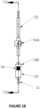
- the fiber ferrule 12 and ferrule adapter 14 are also shown in Figure 1C.
- the ferrule 12 has a diameter of 1.7 mm and length of approximately 25 mm.
- the adapter 14 it is fixed to the exterior of the ferrule 12, and has a laterally-extending magnet holder 18.
- cylindrical magnet 16a Located within the magnet holder 18 is cylindrical magnet 16a, which preferably has the same diameter and bore as magnet 16b. Magnet 16a is fixed within the magnet holder 18, which is located to align with the magnet 16b when the fiber assembly and lens assembly are connected together.
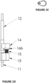
- the position of the screw 15 and magnet 16b will affect the relative positioning of the fiber assembly and the lens assembly.
- the ferrule adapter 14 is fixed to the ferrule 12, such as by gluing, at a position that results in the fiber being adjacent to the tapered surface 13c of the collet 13 when the screw 15 is fully screwed into the threaded aperture of the collet.
- the point of contact between the magnets 16a and 16b moves further from collet 13, and the distal end of the ferrule 12 moves away from the tapered surface 13c, while remaining in the receiving aperture 13a.
- the distance between the tip of the fiber and the lens, and thereby the focusing of the lens on the fiber can be changed by adjusting the screw from the top.
- the focusing between the lens 11 and the fiber of ferrule 12 is adjustable by rotating the screw to change the distance between a tip of the ferrule 12 and the lens 11.
- This focusing adjustment allows the connector to compensate for differences in how the lens 11 may be positioned relative to the imaging target, such as the brain tissue of a mammal being examined. Different positioning of the lens may result in different necessary focusing adjustments, but since the grin lens may be fixed in position, and the focusing adjustment remains with the collet 13 and lens 11, the adjustment does not need to be repeated each time the fiber assembly is reconnected to the lens assembly.
- the connector allows for simple, repeatable connections between the fiber assembly and one or more lens assemblies.
- the configuration of the connector is also particularly suitable for miniaturized applications like imaging of the brain of a small rodent, such as a mouse.
- the size of the connector is small enough that a number of connectors (e.g., four) can fit on the head of a mouse.
- the lens 11 may have a diameter of 1.0 mm, and a length of about 4 mm.
- the collet With the screw 15 fully inserted into the threaded aperture of the collet 13, the collet has an overall length of about 7.3 mm, and a maximum width of about 5 mm.
- the ferrule of this embodiment has a diameter of about 1.7 mm and a length of approximately 25 mm.
- the connector is also well suited to use by a single user.
- the design allows a user to change the focus when the lens is implanted in the head of an animal, such as a mouse, while the animal is awake and minimally restrained, by allowing, for example, the user to hold the animal with one hand and change the focus with the other hand.
- a user can do this for a number of implants, e. g. four, very quickly, as the focusing mechanism for each of the lens assembly implants is easily accessible, accurate and fast.
- the subject e.g. a mouse
- the image remains completely stable, as there is no relative movement between the lens and fiber once it is fixed in place.
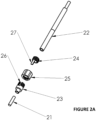
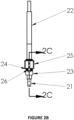
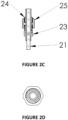
- FIG. 2A to 2D Shown in Figures 2A to 2D is an alternative embodiment of the invention that has a more slender profile than the embodiment of Figures 1A - 1E .
- a grin lens 21 is shown adjacent to a collet 23 having an aperture that receives the lens 21.
- the collet 23 has a slot 26 that receives a key 27 that extends from a fiber ferrule adapter 24 that is fixed on fiber ferrule 22.
- the collet 23 has a threaded exterior that meshes with an internal thread at a distal end of nut 25, while the ferrule adapter 24 has a threaded exterior that meshes with an internal thread at a proximal end of nut 25.
- tab 27 of the ferrule adapter 24 is located in the slot 26 of the collet 23, thereby maintaining a constant relative rotational orientation of the ferrule adapter and the lens 21. This relative orientation remains regardless of how many times the user disconnects and reconnects the fiber to the lens.
- the lens 21 is glued to the collet 23 and the ferrule adapter 24 is glued to the fiber ferrule 22.
- the embodiment of Figures 2A -2D provides miniature repeatable fiber-lens connector that may be used for small animal imaging.
- the profile of the connector is slimmer, and there are fewer components, but the focus setting is not automatically retained when the fiber ferrule 22 is disconnected from the lens 21 and collet 23.
- the number of turns of the nut 25 may be recorded, or a marking on either or both of the collet 23 and ferrule adapter 27 may be used to identify the proper rotational position of the nut at a desired focus.
Landscapes
- Physics & Mathematics (AREA)
- Optics & Photonics (AREA)
- General Physics & Mathematics (AREA)
- Health & Medical Sciences (AREA)
- Life Sciences & Earth Sciences (AREA)
- Surgery (AREA)
- Heart & Thoracic Surgery (AREA)
- Animal Behavior & Ethology (AREA)
- Radiology & Medical Imaging (AREA)
- Nuclear Medicine, Radiotherapy & Molecular Imaging (AREA)
- Engineering & Computer Science (AREA)
- Biomedical Technology (AREA)
- Biophysics (AREA)
- Medical Informatics (AREA)
- Molecular Biology (AREA)
- Pathology (AREA)
- General Health & Medical Sciences (AREA)
- Public Health (AREA)
- Veterinary Medicine (AREA)
- Astronomy & Astrophysics (AREA)
- Mechanical Coupling Of Light Guides (AREA)
- Optical Couplings Of Light Guides (AREA)
- Endoscopes (AREA)
- Lens Barrels (AREA)
- Focusing (AREA)
Claims (9)
- Optischer Bildgebungsverbinder, umfassend:eine Faseranordnung, umfassend:eine optische Faserhülse (12), in der eine optische Faser zum Transportieren eines optischen Bildes angeordnet ist; undeinen an der Hülse (12) befestigten Hülsenadapter (14); undeine Linsenanordnung, umfassend:eine Linse (11) mit einem distalen Ende, das konfiguriert ist, um angrenzend an ein Bildgebungsziel befestigt zu werden; undeinen Linsenhalter (13), in dem die Linse (11) mit ihrem proximalen Ende angrenzend an eine Hülsenaufnahme angebracht ist, die die Hülse (12) aufnimmt und sie in einer im Wesentlichen koaxialen Beziehung zur Linse (11) hält, dadurch gekennzeichnet, dassder Hülsenadapter (14) eine radiale Verlängerung mit einem ersten Kopplungsabschnitt aufweist und der Linsenhalter (13) eine radiale Verlängerung mit einem zweiten Kopplungsabschnitt aufweist, der mit dem ersten Kopplungsabschnitt in Eingriff steht, um die Faseranordnung abnehmbar mit der Linsenanordnung zu koppeln; unddie Linsenanordnung ferner einen Fokuseinstellmechanismus umfasst, der von einem Benutzer manuell einstellbar ist, um eine Längsposition des zweiten Kopplungsabschnitts relativ zum Linsenhalter (13) zu ändern und dadurch eine axiale Position der Hülse in der Hülsenaufnahme zu ändern.
- Optischer Bildgebungsverbinder nach Anspruch 1, wobei der erste und der zweite Kopplungsabschnitt mindestens ein magnetisches Element (16a, 16b) umfassen, das eine magnetische Anziehung zwischen dem ersten und dem zweiten Kopplungsabschnitt bereitstellt.
- Optischer Bildgebungsverbinder nach Anspruch 1 oder 2, wobei der erste und der zweite Kopplungsabschnitt jeweils ein magnetisches Element (16a, 16b) umfassen und die magnetischen Elemente sich gegenseitig anziehen.
- Optischer Bildgebungsverbinder nach einem der Ansprüche 1 bis 3, wobei die radiale Verlängerung des Linsenhalters (13) eine Gewindeöffnung (13b) aufweist und der Fokuseinstellmechanismus eine Schraube (15) mit einem Außengewinde umfasst, das mit einem Innengewinde der Gewindeöffnung (13b) ineinandergreift und die Längsposition des zweiten Kopplungsabschnitts bei Drehung der Schraube verändert.
- Optischer Bildgebungsverbinder nach Anspruch 4, wobei der Kopf der Schraube zu einem proximalen Ende des Verbinders zeigt, um den Zugang für den Benutzer zu erleichtern.
- Optischer Bildgebungsverbinder nach einem der Ansprüche 1 bis 5, wobei die Hülsenaufnahme eine ringförmige Innenfläche angrenzend an das proximale Ende der Linse aufweist, die eine Begrenzung für das Ausmaß darstellt, in dem die Hülse in den Linsenhalter eingeführt werden kann, um einen Kontakt zwischen der Hülse und der Linse zu verhindern.
- Optischer Bildgebungsverbinder nach einem der Ansprüche 1 bis 6, wobei der Eingriff zwischen dem ersten Kopplungsabschnitt und dem zweiten Kopplungsabschnitt eine konstante relative Winkelausrichtung zwischen der Faseranordnung und der Linsenanordnung aufrechterhält.
- Optischer Bildgebungsverbinder nach einem der Ansprüche 2 bis 7, wenn abhängig von den Ansprüchen 2 oder 3, wobei der zweite Kopplungsabschnitt an dem Fokuseinstellmechanismus angebracht ist.
- Optischer Bildgebungsverbinder nach einem der Ansprüche 1 bis 8, wobei der Fokuseinstellmechanismus für den Benutzer von einem proximalen Ende des Verbinders aus zugänglich ist.
Applications Claiming Priority (2)
| Application Number | Priority Date | Filing Date | Title |
|---|---|---|---|
| US201762584118P | 2017-11-10 | 2017-11-10 | |
| PCT/CA2018/051422 WO2019090432A1 (en) | 2017-11-10 | 2018-11-09 | Miniature lens-fiber connector with live focusing capability |
Publications (3)
| Publication Number | Publication Date |
|---|---|
| EP3707539A1 EP3707539A1 (de) | 2020-09-16 |
| EP3707539A4 EP3707539A4 (de) | 2021-08-25 |
| EP3707539B1 true EP3707539B1 (de) | 2025-04-09 |
Family
ID=66437492
Family Applications (1)
| Application Number | Title | Priority Date | Filing Date |
|---|---|---|---|
| EP18875329.7A Active EP3707539B1 (de) | 2017-11-10 | 2018-11-09 | Miniaturobjektiv-faserverbinder mit live-fokussierung |
Country Status (4)
| Country | Link |
|---|---|
| US (1) | US11291353B2 (de) |
| EP (1) | EP3707539B1 (de) |
| JP (2) | JP7399078B2 (de) |
| WO (1) | WO2019090432A1 (de) |
Families Citing this family (3)
| Publication number | Priority date | Publication date | Assignee | Title |
|---|---|---|---|---|
| EP3707539B1 (de) * | 2017-11-10 | 2025-04-09 | Neurescence Inc. | Miniaturobjektiv-faserverbinder mit live-fokussierung |
| US12189190B1 (en) * | 2022-03-04 | 2025-01-07 | Amazon Technologies, Inc. | Connector for optical fibers |
| US12704687B2 (en) * | 2023-02-01 | 2026-08-11 | Rtx Corporation | Indexed optical coupler for coupling optical fibers |
Family Cites Families (20)
| Publication number | Priority date | Publication date | Assignee | Title |
|---|---|---|---|---|
| US3941121A (en) * | 1974-12-20 | 1976-03-02 | The University Of Cincinnati | Focusing fiber-optic needle endoscope |
| JPH043407U (de) * | 1990-04-24 | 1992-01-13 | ||
| JP2583739Y2 (ja) * | 1991-02-25 | 1998-10-27 | 株式会社フジクラ | イメージファイバコネクタ |
| JP2592853Y2 (ja) * | 1992-02-20 | 1999-03-31 | 株式会社東芝 | 光モジュール |
| JPH0627393A (ja) * | 1992-07-06 | 1994-02-04 | Hooya Shiyotsuto Kk | 観察装置 |
| US5575757A (en) * | 1992-10-09 | 1996-11-19 | Smith & Nephew Endoscopy Inc. | Endoscope with focusing mechanism |
| US5359992A (en) * | 1992-10-20 | 1994-11-01 | Linvatec Corporation | Endoscope coupler with magnetic focus control |
| JP2743249B2 (ja) * | 1994-05-13 | 1998-04-22 | 三菱電線工業株式会社 | 光コリメータ |
| US5836867A (en) * | 1996-11-27 | 1998-11-17 | Linvatec Corporation | Magnetic coupling assembly for endoscope |
| US6099467A (en) * | 1998-03-27 | 2000-08-08 | Karl Storz Gmbh & Co. Kg | Device for positioning components within endoscopic systems |
| US6616602B1 (en) * | 1999-06-18 | 2003-09-09 | Olympus Winter & Ibe Gmbh | Endoscope with magnetic actuation |
| US8343042B2 (en) * | 2005-07-11 | 2013-01-01 | Lighthouse Imaging Corporation | Magnetically actuated endoscope coupler |
| JP3987078B2 (ja) * | 2005-08-31 | 2007-10-03 | 日本電信電話株式会社 | 光コネクタ |
| US7431513B2 (en) * | 2006-01-20 | 2008-10-07 | Oz Optics Ltd. | Adjustable focus connector with spring action |
| US7695202B1 (en) * | 2008-07-21 | 2010-04-13 | Michael Brubacher | Visual laser diode to fiber coupling system |
| DE102011078969B4 (de) * | 2011-07-11 | 2019-02-21 | Olympus Winter & Ibe Gmbh | Berührungslose Magnetkupplung für ein Endoskop und Endoskop |
| JP2015206912A (ja) * | 2014-04-21 | 2015-11-19 | オリンパス株式会社 | 光ファイバの接続アダプタおよび内視鏡装置 |
| WO2016084113A1 (ja) * | 2014-11-26 | 2016-06-02 | オリンパス株式会社 | 光ファイバ接続機構および光ファイバ接続方法 |
| DE102017205590B3 (de) * | 2017-04-03 | 2017-12-14 | Asphericon Gmbh | Justierbarer Faserkollimator und Verfahren zu dessen Montage |
| EP3707539B1 (de) * | 2017-11-10 | 2025-04-09 | Neurescence Inc. | Miniaturobjektiv-faserverbinder mit live-fokussierung |
-
2018
- 2018-11-09 EP EP18875329.7A patent/EP3707539B1/de active Active
- 2018-11-09 WO PCT/CA2018/051422 patent/WO2019090432A1/en not_active Ceased
- 2018-11-09 JP JP2020510611A patent/JP7399078B2/ja active Active
- 2018-11-09 US US16/627,629 patent/US11291353B2/en active Active
-
2023
- 2023-01-27 JP JP2023010970A patent/JP7566061B2/ja active Active
Also Published As
| Publication number | Publication date |
|---|---|
| EP3707539A4 (de) | 2021-08-25 |
| WO2019090432A1 (en) | 2019-05-16 |
| CA3081108A1 (en) | 2019-05-16 |
| EP3707539A1 (de) | 2020-09-16 |
| US11291353B2 (en) | 2022-04-05 |
| JP7566061B2 (ja) | 2024-10-11 |
| JP2023056525A (ja) | 2023-04-19 |
| US20210145260A1 (en) | 2021-05-20 |
| JP7399078B2 (ja) | 2023-12-15 |
| JP2021502583A (ja) | 2021-01-28 |
Similar Documents
| Publication | Publication Date | Title |
|---|---|---|
| JP7566061B2 (ja) | 生態の焦点合わせ機能を有する小型のレンズ-ファイバ間コネクタ | |
| US20250134599A1 (en) | Universal tool adapter | |
| DE60203242T2 (de) | Verdrehbare Endoskope mit abgewinkeltem Distalvisier | |
| ES2989609T3 (es) | Conector de cable de fibra óptica | |
| EP2080050B1 (de) | Vorrichtung zum einkoppeln von licht in eine lichtleitfaser | |
| EP1430344B1 (de) | Steckverbinder für ein kombinationskabel | |
| EP2838414B1 (de) | Rotationsvorrichtung zum rotieren eines endoskops | |
| US20210093168A1 (en) | An adapter for a multi-stage console connector | |
| US5577143A (en) | Multi channel connector | |
| DE19837404A1 (de) | Endoskop | |
| JPS62502500A (ja) | 内視鏡 | |
| EP1990665B1 (de) | System und Vorrichtung für einen faseroptischen Steckverbinder | |
| EP2312370A2 (de) | Kameraadapter mit Kamerahalterung und Optikadapter | |
| JP7339949B2 (ja) | 手術シミュレーション用カメラスコープ | |
| CN211674365U (zh) | 一种夹持器 | |
| DE19942152A1 (de) | Endoskop | |
| US8764315B2 (en) | Connector for a fiber probe and a fiber probe adapted to said connector | |
| DE69823092T2 (de) | Faseroptischer Stecker | |
| JPS6037527Y2 (ja) | 光フアイバ伝送路用コネクタ | |
| US20210153852A1 (en) | Surgical instrument retainer device | |
| DE112021004125T5 (de) | Bildaufnahmevorrichtung und endoskop | |
| CN113180574A (zh) | 内窥镜的快插结构及内窥镜 | |
| CN223333179U (zh) | 一种fc连接器 | |
| CN219557399U (zh) | 脑深部电极植入设备 | |
| CN217090663U (zh) | 一种内窥镜 |
Legal Events
| Date | Code | Title | Description |
|---|---|---|---|
| STAA | Information on the status of an ep patent application or granted ep patent |
Free format text: STATUS: THE INTERNATIONAL PUBLICATION HAS BEEN MADE |
|
| PUAI | Public reference made under article 153(3) epc to a published international application that has entered the european phase |
Free format text: ORIGINAL CODE: 0009012 |
|
| STAA | Information on the status of an ep patent application or granted ep patent |
Free format text: STATUS: REQUEST FOR EXAMINATION WAS MADE |
|
| 17P | Request for examination filed |
Effective date: 20200331 |
|
| AK | Designated contracting states |
Kind code of ref document: A1 Designated state(s): AL AT BE BG CH CY CZ DE DK EE ES FI FR GB GR HR HU IE IS IT LI LT LU LV MC MK MT NL NO PL PT RO RS SE SI SK SM TR |
|
| AX | Request for extension of the european patent |
Extension state: BA ME |
|
| DAV | Request for validation of the european patent (deleted) | ||
| DAX | Request for extension of the european patent (deleted) | ||
| A4 | Supplementary search report drawn up and despatched |
Effective date: 20210727 |
|
| RIC1 | Information provided on ipc code assigned before grant |
Ipc: G02B 6/32 20060101AFI20210721BHEP Ipc: A61B 1/07 20060101ALI20210721BHEP Ipc: A61B 1/313 20060101ALI20210721BHEP Ipc: G02B 6/38 20060101ALI20210721BHEP Ipc: G02B 7/04 20210101ALI20210721BHEP |
|
| STAA | Information on the status of an ep patent application or granted ep patent |
Free format text: STATUS: EXAMINATION IS IN PROGRESS |
|
| 17Q | First examination report despatched |
Effective date: 20230512 |
|
| GRAP | Despatch of communication of intention to grant a patent |
Free format text: ORIGINAL CODE: EPIDOSNIGR1 |
|
| STAA | Information on the status of an ep patent application or granted ep patent |
Free format text: STATUS: GRANT OF PATENT IS INTENDED |
|
| INTG | Intention to grant announced |
Effective date: 20241029 |
|
| GRAS | Grant fee paid |
Free format text: ORIGINAL CODE: EPIDOSNIGR3 |
|
| GRAA | (expected) grant |
Free format text: ORIGINAL CODE: 0009210 |
|
| STAA | Information on the status of an ep patent application or granted ep patent |
Free format text: STATUS: THE PATENT HAS BEEN GRANTED |
|
| AK | Designated contracting states |
Kind code of ref document: B1 Designated state(s): AL AT BE BG CH CY CZ DE DK EE ES FI FR GB GR HR HU IE IS IT LI LT LU LV MC MK MT NL NO PL PT RO RS SE SI SK SM TR |
|
| REG | Reference to a national code |
Ref country code: GB Ref legal event code: FG4D |
|
| REG | Reference to a national code |
Ref country code: CH Ref legal event code: EP |
|
| REG | Reference to a national code |
Ref country code: DE Ref legal event code: R096 Ref document number: 602018081037 Country of ref document: DE |
|
| REG | Reference to a national code |
Ref country code: IE Ref legal event code: FG4D |
|
| REG | Reference to a national code |
Ref country code: NL Ref legal event code: MP Effective date: 20250409 |
|
| PG25 | Lapsed in a contracting state [announced via postgrant information from national office to epo] |
Ref country code: NL Free format text: LAPSE BECAUSE OF FAILURE TO SUBMIT A TRANSLATION OF THE DESCRIPTION OR TO PAY THE FEE WITHIN THE PRESCRIBED TIME-LIMIT Effective date: 20250409 |
|
| REG | Reference to a national code |
Ref country code: AT Ref legal event code: MK05 Ref document number: 1784014 Country of ref document: AT Kind code of ref document: T Effective date: 20250409 |
|
| PG25 | Lapsed in a contracting state [announced via postgrant information from national office to epo] |
Ref country code: ES Free format text: LAPSE BECAUSE OF FAILURE TO SUBMIT A TRANSLATION OF THE DESCRIPTION OR TO PAY THE FEE WITHIN THE PRESCRIBED TIME-LIMIT Effective date: 20250409 Ref country code: FI Free format text: LAPSE BECAUSE OF FAILURE TO SUBMIT A TRANSLATION OF THE DESCRIPTION OR TO PAY THE FEE WITHIN THE PRESCRIBED TIME-LIMIT Effective date: 20250409 Ref country code: PT Free format text: LAPSE BECAUSE OF FAILURE TO SUBMIT A TRANSLATION OF THE DESCRIPTION OR TO PAY THE FEE WITHIN THE PRESCRIBED TIME-LIMIT Effective date: 20250811 |
|
| REG | Reference to a national code |
Ref country code: LT Ref legal event code: MG9D |
|
| PG25 | Lapsed in a contracting state [announced via postgrant information from national office to epo] |
Ref country code: GR Free format text: LAPSE BECAUSE OF FAILURE TO SUBMIT A TRANSLATION OF THE DESCRIPTION OR TO PAY THE FEE WITHIN THE PRESCRIBED TIME-LIMIT Effective date: 20250710 Ref country code: NO Free format text: LAPSE BECAUSE OF FAILURE TO SUBMIT A TRANSLATION OF THE DESCRIPTION OR TO PAY THE FEE WITHIN THE PRESCRIBED TIME-LIMIT Effective date: 20250709 |
|
| PG25 | Lapsed in a contracting state [announced via postgrant information from national office to epo] |
Ref country code: PL Free format text: LAPSE BECAUSE OF FAILURE TO SUBMIT A TRANSLATION OF THE DESCRIPTION OR TO PAY THE FEE WITHIN THE PRESCRIBED TIME-LIMIT Effective date: 20250409 |
|
| PG25 | Lapsed in a contracting state [announced via postgrant information from national office to epo] |
Ref country code: BG Free format text: LAPSE BECAUSE OF FAILURE TO SUBMIT A TRANSLATION OF THE DESCRIPTION OR TO PAY THE FEE WITHIN THE PRESCRIBED TIME-LIMIT Effective date: 20250409 |
|
| PG25 | Lapsed in a contracting state [announced via postgrant information from national office to epo] |
Ref country code: HR Free format text: LAPSE BECAUSE OF FAILURE TO SUBMIT A TRANSLATION OF THE DESCRIPTION OR TO PAY THE FEE WITHIN THE PRESCRIBED TIME-LIMIT Effective date: 20250409 |
|
| PG25 | Lapsed in a contracting state [announced via postgrant information from national office to epo] |
Ref country code: AT Free format text: LAPSE BECAUSE OF FAILURE TO SUBMIT A TRANSLATION OF THE DESCRIPTION OR TO PAY THE FEE WITHIN THE PRESCRIBED TIME-LIMIT Effective date: 20250409 |
|
| PG25 | Lapsed in a contracting state [announced via postgrant information from national office to epo] |
Ref country code: RS Free format text: LAPSE BECAUSE OF FAILURE TO SUBMIT A TRANSLATION OF THE DESCRIPTION OR TO PAY THE FEE WITHIN THE PRESCRIBED TIME-LIMIT Effective date: 20250709 |
|
| PG25 | Lapsed in a contracting state [announced via postgrant information from national office to epo] |
Ref country code: IS Free format text: LAPSE BECAUSE OF FAILURE TO SUBMIT A TRANSLATION OF THE DESCRIPTION OR TO PAY THE FEE WITHIN THE PRESCRIBED TIME-LIMIT Effective date: 20250809 |
|
| PG25 | Lapsed in a contracting state [announced via postgrant information from national office to epo] |
Ref country code: LV Free format text: LAPSE BECAUSE OF FAILURE TO SUBMIT A TRANSLATION OF THE DESCRIPTION OR TO PAY THE FEE WITHIN THE PRESCRIBED TIME-LIMIT Effective date: 20250409 |
|
| REG | Reference to a national code |
Ref country code: CH Ref legal event code: U11 Free format text: ST27 STATUS EVENT CODE: U-0-0-U10-U11 (AS PROVIDED BY THE NATIONAL OFFICE) Effective date: 20251201 |
|
| PGFP | Annual fee paid to national office [announced via postgrant information from national office to epo] |
Ref country code: DE Payment date: 20251126 Year of fee payment: 8 |
|
| PGFP | Annual fee paid to national office [announced via postgrant information from national office to epo] |
Ref country code: GB Payment date: 20251128 Year of fee payment: 8 |
|
| REG | Reference to a national code |
Ref country code: DE Ref legal event code: R097 Ref document number: 602018081037 Country of ref document: DE |
|
| PG25 | Lapsed in a contracting state [announced via postgrant information from national office to epo] |
Ref country code: SM Free format text: LAPSE BECAUSE OF FAILURE TO SUBMIT A TRANSLATION OF THE DESCRIPTION OR TO PAY THE FEE WITHIN THE PRESCRIBED TIME-LIMIT Effective date: 20250409 Ref country code: DK Free format text: LAPSE BECAUSE OF FAILURE TO SUBMIT A TRANSLATION OF THE DESCRIPTION OR TO PAY THE FEE WITHIN THE PRESCRIBED TIME-LIMIT Effective date: 20250409 |
|
| PGFP | Annual fee paid to national office [announced via postgrant information from national office to epo] |
Ref country code: FR Payment date: 20251125 Year of fee payment: 8 |
|
| PGFP | Annual fee paid to national office [announced via postgrant information from national office to epo] |
Ref country code: CH Payment date: 20251201 Year of fee payment: 8 |
|
| PG25 | Lapsed in a contracting state [announced via postgrant information from national office to epo] |
Ref country code: CZ Free format text: LAPSE BECAUSE OF FAILURE TO SUBMIT A TRANSLATION OF THE DESCRIPTION OR TO PAY THE FEE WITHIN THE PRESCRIBED TIME-LIMIT Effective date: 20250409 |
|
| PG25 | Lapsed in a contracting state [announced via postgrant information from national office to epo] |
Ref country code: EE Free format text: LAPSE BECAUSE OF FAILURE TO SUBMIT A TRANSLATION OF THE DESCRIPTION OR TO PAY THE FEE WITHIN THE PRESCRIBED TIME-LIMIT Effective date: 20250409 |
|
| PG25 | Lapsed in a contracting state [announced via postgrant information from national office to epo] |
Ref country code: SK Free format text: LAPSE BECAUSE OF FAILURE TO SUBMIT A TRANSLATION OF THE DESCRIPTION OR TO PAY THE FEE WITHIN THE PRESCRIBED TIME-LIMIT Effective date: 20250409 Ref country code: RO Free format text: LAPSE BECAUSE OF FAILURE TO SUBMIT A TRANSLATION OF THE DESCRIPTION OR TO PAY THE FEE WITHIN THE PRESCRIBED TIME-LIMIT Effective date: 20250409 |
|
| PG25 | Lapsed in a contracting state [announced via postgrant information from national office to epo] |
Ref country code: IT Free format text: LAPSE BECAUSE OF FAILURE TO SUBMIT A TRANSLATION OF THE DESCRIPTION OR TO PAY THE FEE WITHIN THE PRESCRIBED TIME-LIMIT Effective date: 20250409 |
|
| PLBE | No opposition filed within time limit |
Free format text: ORIGINAL CODE: 0009261 |
|
| STAA | Information on the status of an ep patent application or granted ep patent |
Free format text: STATUS: NO OPPOSITION FILED WITHIN TIME LIMIT |
|
| REG | Reference to a national code |
Ref country code: CH Ref legal event code: L10 Free format text: ST27 STATUS EVENT CODE: U-0-0-L10-L00 (AS PROVIDED BY THE NATIONAL OFFICE) Effective date: 20260218 |
|
| 26N | No opposition filed |
Effective date: 20260112 |
|
| PG25 | Lapsed in a contracting state [announced via postgrant information from national office to epo] |
Ref country code: LT Free format text: LAPSE BECAUSE OF FAILURE TO SUBMIT A TRANSLATION OF THE DESCRIPTION OR TO PAY THE FEE WITHIN THE PRESCRIBED TIME-LIMIT Effective date: 20250409 |
|
| PG25 | Lapsed in a contracting state [announced via postgrant information from national office to epo] |
Ref country code: MC Free format text: LAPSE BECAUSE OF FAILURE TO SUBMIT A TRANSLATION OF THE DESCRIPTION OR TO PAY THE FEE WITHIN THE PRESCRIBED TIME-LIMIT Effective date: 20250409 |
|
| PG25 | Lapsed in a contracting state [announced via postgrant information from national office to epo] |
Ref country code: LU Free format text: LAPSE BECAUSE OF NON-PAYMENT OF DUE FEES Effective date: 20251109 |
|
| PG25 | Lapsed in a contracting state [announced via postgrant information from national office to epo] |
Ref country code: SE Free format text: LAPSE BECAUSE OF FAILURE TO SUBMIT A TRANSLATION OF THE DESCRIPTION OR TO PAY THE FEE WITHIN THE PRESCRIBED TIME-LIMIT Effective date: 20250409 |