EP1990665B1 - System und Vorrichtung für einen faseroptischen Steckverbinder - Google Patents
System und Vorrichtung für einen faseroptischen Steckverbinder Download PDFInfo
- Publication number
- EP1990665B1 EP1990665B1 EP08251651.9A EP08251651A EP1990665B1 EP 1990665 B1 EP1990665 B1 EP 1990665B1 EP 08251651 A EP08251651 A EP 08251651A EP 1990665 B1 EP1990665 B1 EP 1990665B1
- Authority
- EP
- European Patent Office
- Prior art keywords
- ferrules
- pair
- termini
- receptacle
- fiber optic
- Prior art date
- Legal status (The legal status is an assumption and is not a legal conclusion. Google has not performed a legal analysis and makes no representation as to the accuracy of the status listed.)
- Ceased
Links
- 239000000835 fiber Substances 0.000 title claims description 34
- 239000013307 optical fiber Substances 0.000 claims description 18
- 230000003287 optical effect Effects 0.000 claims description 15
- 230000004323 axial length Effects 0.000 claims description 7
- 230000014759 maintenance of location Effects 0.000 claims description 6
- 229910010293 ceramic material Inorganic materials 0.000 claims description 3
- 229910001220 stainless steel Inorganic materials 0.000 claims description 3
- 239000010935 stainless steel Substances 0.000 claims description 3
- 230000001681 protective effect Effects 0.000 claims description 2
- 238000004140 cleaning Methods 0.000 description 7
- 230000013011 mating Effects 0.000 description 4
- 230000008901 benefit Effects 0.000 description 3
- 238000000034 method Methods 0.000 description 2
- 239000002245 particle Substances 0.000 description 2
- 230000000712 assembly Effects 0.000 description 1
- 238000000429 assembly Methods 0.000 description 1
- 230000015556 catabolic process Effects 0.000 description 1
- 239000000919 ceramic Substances 0.000 description 1
- 238000006731 degradation reaction Methods 0.000 description 1
- 230000007613 environmental effect Effects 0.000 description 1
- 239000003344 environmental pollutant Substances 0.000 description 1
- 238000007689 inspection Methods 0.000 description 1
- 238000004519 manufacturing process Methods 0.000 description 1
- 239000002184 metal Substances 0.000 description 1
- 231100000719 pollutant Toxicity 0.000 description 1
- 239000000523 sample Substances 0.000 description 1
Images
Classifications
-
- G—PHYSICS
- G02—OPTICS
- G02B—OPTICAL ELEMENTS, SYSTEMS OR APPARATUS
- G02B6/00—Light guides; Structural details of arrangements comprising light guides and other optical elements, e.g. couplings
- G02B6/24—Coupling light guides
- G02B6/36—Mechanical coupling means
- G02B6/38—Mechanical coupling means having fibre to fibre mating means
- G02B6/3807—Dismountable connectors, i.e. comprising plugs
- G02B6/381—Dismountable connectors, i.e. comprising plugs of the ferrule type, e.g. fibre ends embedded in ferrules, connecting a pair of fibres
- G02B6/3825—Dismountable connectors, i.e. comprising plugs of the ferrule type, e.g. fibre ends embedded in ferrules, connecting a pair of fibres with an intermediate part, e.g. adapter, receptacle, linking two plugs
-
- G—PHYSICS
- G02—OPTICS
- G02B—OPTICAL ELEMENTS, SYSTEMS OR APPARATUS
- G02B6/00—Light guides; Structural details of arrangements comprising light guides and other optical elements, e.g. couplings
- G02B6/24—Coupling light guides
- G02B6/36—Mechanical coupling means
- G02B6/38—Mechanical coupling means having fibre to fibre mating means
- G02B6/3807—Dismountable connectors, i.e. comprising plugs
- G02B6/3873—Connectors using guide surfaces for aligning ferrule ends, e.g. tubes, sleeves, V-grooves, rods, pins, balls
- G02B6/3885—Multicore or multichannel optical connectors, i.e. one single ferrule containing more than one fibre, e.g. ribbon type
-
- G—PHYSICS
- G02—OPTICS
- G02B—OPTICAL ELEMENTS, SYSTEMS OR APPARATUS
- G02B6/00—Light guides; Structural details of arrangements comprising light guides and other optical elements, e.g. couplings
- G02B6/24—Coupling light guides
- G02B6/36—Mechanical coupling means
- G02B6/38—Mechanical coupling means having fibre to fibre mating means
- G02B6/3807—Dismountable connectors, i.e. comprising plugs
- G02B6/3897—Connectors fixed to housings, casing, frames or circuit boards
-
- G—PHYSICS
- G02—OPTICS
- G02B—OPTICAL ELEMENTS, SYSTEMS OR APPARATUS
- G02B6/00—Light guides; Structural details of arrangements comprising light guides and other optical elements, e.g. couplings
- G02B6/24—Coupling light guides
- G02B6/36—Mechanical coupling means
- G02B6/38—Mechanical coupling means having fibre to fibre mating means
- G02B6/3807—Dismountable connectors, i.e. comprising plugs
- G02B6/3833—Details of mounting fibres in ferrules; Assembly methods; Manufacture
- G02B6/3853—Lens inside the ferrule
Definitions
- the present invention relates in general to fiber optics and, in particular, to an improved fiber optic connector assembly.
- the socket terminii are typically spring-loaded and recessed in an alignment sleeve to mate with respective pins on a receptacle.
- the sockets are usually placed in a plug on a flexible harness to make their difficult-to-clean recessed end faces easier to access during cleaning operations.
- the fixed, bulkhead-mounted receptacles usually contain the easier-to-clean termination pins because they are typically more difficult to access during cleaning operations.
- expanded beam connectors that require the plug and receptacle style.
- a significant benefit of expanded beam connectors is that with a larger beam size, dirt particles block a smaller percentage of the light and therefore have lesser impact on system performance.
- all current expanded beam connectors use ball lenses in front of the fibers.
- the fiber must be placed at a very precise distance from the ball lens to allow the light to expand to a fixed diameter before the ball lens collimates the beam.
- the receiving fiber also requires a ball lens to receive the collimated light and re-focus it back into the receiving fiber.
- One problem with this design is that the fibers must be exactly the same distances from the ball lenses, and this requirement must be precisely maintained regardless of the environmental conditions in which operation is required. Unfortunately, the distances comprise air gaps that can become contaminated with pollutants, and the distances expand and contract with temperature. Consequently, the production of these connections is very difficult and requires very specialized equipment.
- U.S. 4,733,936 discloses a fiber optic connector assembly that includes connector members 10,20, connector shells, 12,22, optical fibers, 17,27, metal sleeves, 18,28, and lenses, 30, 30'.
- the ends of the optical fibers 17,27 of D1 are always in physical contact with the lenses, 30, 30'.
- a fiber optic connector assembly is provided according to claim 1.
- the receptacle incorporates ball lenses, rod lenses (also known as a GRIN (Graded Index) lens or SELFOC (self-focusing) lens), or any other optical component that accomplishes the desired beam manipulation with the required diameters and lengths.
- a rod lens essentially comprises a very large fiber that has a graded index profile that forms the light into a sine wave. The length of the rod lens determines where the sine wave is trimmed to selectively expand, collimate and focus the light.
- the simplified design allows for the use of a single style of plug on the ends of all harnesses and incorporates spring-loaded sockets in the plugs to ensure proper positioning of the optical fibers with respect to the receptacle.
- only one type of plug is required for the ends of all harnesses, and only one type of receptacle is required to mate with the plugs, which greatly reduces the risk of attaching the wrong parts during assembly.
- the receptacle incorporates a mirror image pin design and may be used on bulkhead receptacles or connections to boxes, with which two of the plugs mate (i.e., one on each end of the receptacle).
- the pin in the receptacle has a ferrule that protrudes from the end faces of the receptacle in the same manner as pin terminii, which greatly simplifies the cleaning of these parts.
- This receptacle uses a pair of optical lenses on each socket for expanding, collimating, and focusing the beam from the plug terminii.
- the optical components are captured in a ferrule that holds the components, contains a ring, disk, or ledge that sets the distance between the plug terminii and the lenses, and provides the alignment needed between the plug ferrules and the optical components.
- the optical components are recessed in the pin ferrule, but the optical beam is expanded making cleaning less critical since particles have less impact on the power throughput.
- both sides of the receptacle can be unthreaded and a quick release attachment for the receptacle allows the receptacle to be readily accessed for cleaning purposes.
- This design also overcomes a significant issue faced by connectors that require physical contact. Damaged end faces or test probes with damaged end faces cannot transfer their damage to the end faces they are mated with since, in this design, no end faces physically touch each other. In addition, it is easier to replace a damaged fiber when the receptacle does not have to be removed, but rather just a plug unthreaded.
- This invention not only makes all cleaning procedures easier and less critical, but it also reduces the requirement for the tight tolerances between the end faces. Moreover, the invention does add volume, and only a minor amount of weight Furthermore, this design improves the reliability of the fiber optic connections, reduces the impact of end face degradation, reduces the reliance on ever more increasing requirements for tighter tolerances on all parts, and reduces costs for the parts.
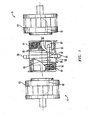
- Figure 1 is an exploded, partially sectioned side view of one embodiment of an optical fiber connector system constructed in accordance with the invention
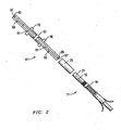
- Figure 2 is an enlarged, exploded, partially sectioned side view of one embodiment of terminii used by the optical fiber connector system of Figure 1 and is constructed in accordance with the invention
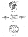
- Figure 3 is an isometric view of a receptacle for the optical fiber connector system of Figure 1 and is constructed in accordance with the invention
- Figure 4 is a schematic side view of another embodiment of a termini for the receptacle of Figure 3 and is constructed in accordance with the invention.
- Figure 5 is an isometric view of a conventional plug that may be used in conjunction with the invention.
- Embodiments of a fiber optic connector assembly that employs an expanded beam receptacle are disclosed.
- a rod lens is used to expand light out of a fiber on one side of the receptacle, and then re-focus the light back into a receiving fiber on the other side of the receptacle.
- the receptacle forms a minor-image connector design that eliminates a pin and socket connection.
- the invention incorporates the external thread specifications from Military D38999-style connectors on both ends of the receptacle instead of just one end.
- the reliability of this design has been proven over many years and recently was improved to work for fiber optics by restricting all mating tolerances to minimize light loss in the mating process.
- the receptacle mates with two conventional D38999 plugs, each of which contains one or more socket terminii (e.g., Mil-T-29504) for mating with features in the receptacle.
- the receptacle is greatly simplified to couple with harnesses having only plugs with socket contacts.
- the receptacles are ideally suited for use on bulkheads and on "boxes" (e.g., stand alone components).
- the one or more pins that extend through the receptacle have unique terminii that may incorporate one or more 1.8 mm ceramic ferrules, but contain a pair of expanded beam connectors (e.g., rod lenses having a 1.0 mm diameter and half-inch 12.7 mm axial length) that set an exact position and proper distance required between the optical fibers in the plugs and the front sides of the lens elements.
- the lenses expand and collimate the light that enters the receptacle from the optical fiber in one of the plugs, and then transmits the collimated light and re-focuses it back into the receiving optical fiber in the opposite plug.
- one embodiment of a system for transmitting fiber optic light comprises a pair of harnesses 11 ( Figure 1 ) having identical plugs 13 ( Figures 1 and 5 ).
- An optical fiber 15 (shown in dashed line and greatly exaggerated in size) extends through respective ones of the plugs 13.
- Each of the optical fibers 15 is mounted in a socket termini 17 ( Figure 2 ) that is spring-loaded 19 and recessed in an alignment sleeve 21, and shrouded in a protective collar 23.
- the socket terminii 17 comprise Mil-T-29504 terminii.
- a receptacle 31 is used to transmit light from one of the optical fibers 15 to the other of the optical fibers 15.
- the receptacle 31 has a tubular body 33 with an axis 35.
- One or more parallel apertures 37 extend through the tubular body 33 in an axial direction.
- a mounting structure such as a flange 39, extends from the tubular body 33 for mounting the receptacle 31 to an object, such as a bulkhead or box.
- the flange 39 may bisect the receptacle 31 and be oriented in a plane that is perpendicular to the axis 35.
- a pair of fastening elements 41 (which may be identical and mirror images of each other) are located on opposite axial sides of the mounting structure 39.
- the identical fastening elements 41 are secured to respective ones of the plugs 13 to form an assembly, and may comprise D38999 external threads as shown.
- One or more pins 51 are mounted in the receptacle 31. Each pin 51 extends through one of the apertures 37, however not all apertures 37 need be populated with pins 51, depending on the application. When receptacle 31 is assembled to plugs 13, the pins 51 mate with the socket terminii 17. Each pin 51 has a termini body 53 with one or more retention shoulders 55 for aligning the pin 51 within a respective aperture 37, In one embodiment, a pair of ferrules 61 ( Figure 2 ) are coaxially mounted in the termini body 53. An expanded beam optical component 63 (e.g., a rod lens ( Figure 2 ), ball lens 64 ( Figure 4 ), etc.) is mounted in each ferrule 61.
- An expanded beam optical component 63 e.g., a rod lens ( Figure 2 ), ball lens 64 ( Figure 4 ), etc.
- Each expanded beam lens 63 has an axial end 65 ( Figure 2 ) that is located adjacent to an axial end 67 of a respective one of the ferrules 61.
- the expanded beam lenses 63 expand and collimate light from one of the optical fibers 15 and focus the light to the other of the optical fibers 15.
- the expanded beam lenses 63 are axially spaced apart from each other as shown, and the axial ends 65 of the expanded beam lenses 63 are axially recessed from the axial ends 67 of respective ones of the ferrules 61.
- the ferrules 61 may be coaxially mounted within the termini body 53 and axially spaced apart from each other as shown.
- the termini body 53 is formed from stainless steel and the ferrules 61 are formed from ceramic material.
- the retention shoulders 55 may be located on axially opposite ends of the termini body 53, and the termini body 53 may be provided with an axial length that is less than an axial length of one or both of the ferrules 61.
Landscapes
- Physics & Mathematics (AREA)
- General Physics & Mathematics (AREA)
- Optics & Photonics (AREA)
- Optical Couplings Of Light Guides (AREA)
- Mechanical Coupling Of Light Guides (AREA)
Claims (13)
- Faseroptische Steckverbinderanordnung, die aufweist:eine Steckbuchse (31) mit einer Achse, einer Öffnung (37), die sich durch die Steckbuchse (31) in einer axialen Richtung erstreckt, einer Befestigungsstruktur (39), die für ein Montieren der Steckbuchse an einem Gegenstand ausgebildet ist, und einem Paar von Befestigungselementen (41), die auf entgegengesetzten Seiten der Befestigungsstruktur (39) angeordnet sind; undeinen Stift (51), der in der Steckbuchse (31) montiert ist und sich durch die axiale Öffnung (37) erstreckt, wobei der Stift aufweist: einen Terminikörper (53) mit mindestens einem Arretiervorsprung (55); eine oder zwei Ferrulen (61), die sich durch den Terminikörper (53) erstrecken; und ein optisches Teil (63) mit erweitertem Strahl, das in dem einen oder den zwei ferrulen (61) montiert ist, wobei das optische Teil (63) mit erweitertem Strahl axiale Enden aufweist, die benachbart an axial entgegengesetzten Enden eines jeden der einen oder der zwei Ferrulen angeordnet sind; undzwei identische Stecker (13), wobeisich mindestens eine optische Faser (15) durch einen jeden der zwei identischen Stecker (13) erstreckt und in einem einer Vielzahl von Buchsentermini (17) montiert und in einer einer Vielzahl von Ausrichtungshülsen (21) versenkt ist, wobei die identischen Stecker (13) jeweils so ausgebildet sind, dass sie an einem jeweiligen des Paares der Befestigungselemente (41) gesichert werden, so dass ein axiales Ende einer der Ferrulen (61) des Stiftes (51) entgegengesetzt dem optischen Teil (63) mit erweitertem Strahl an eine der Buchsentermini (17) durch einen Schutzring (23) anstößt, der die Buchsentermini (17) eines jeden Steckers (13) umhüllt; wobeidas optische Teil (63) mit erweitertem Strahl ausgebildet ist, um Licht von einer der optischen Fasern (15) auszubreiten und zu kollimieren, die mit einem Ende der Steckbuchse verbunden sind, wenn eine der Ferrulen (61) des Stiftes (51) an eine der Buchsentermini (17) von einem der Stecker (13) anstößt und das Licht zu einer anderen der anderen optischen Fasern (15) fokussiert, die mit dem entgegengesetzten Ende der Steckbuchse (31) verbunden sind, wenn der Stift (51) an einen der Buchsentermini (17) im anderen Stecker (13) anstößt; wobeidas optische Teil (63) mit erweitertem Strahl ein Paar Linsen aufweist, die axial voneinander beabstandet sind, und wobei die axialen Enden des Paares der Linsen von den axial entgegengesetzten Enden der einen oder der zwei Ferrulen (61) axial versenkt sind; und wobeidie Ferrule (61) einen Ring, eine Scheibe oder einen Absatz aufweist, die den Abstand zwischen einem jeden der Buchsentermini (17) und einer jeden der Linsen (63) einstellen.
- Faseroptische Steckverbinderanordnung nach Anspruch 1, bei der das Paar der Befestigungselemente (41) Military D38999 Außengewinde aufweist und der Stift (51) ausgebildet ist, um zu den Mil-T-29504 Termini an Kabelbaumsteckern zu passen.
- Faseroptische Steckverbinderanordnung nach Anspruch 1, bei der die eine oder die zwei Ferrulen (61) ein Paar Ferrulen aufweisen, die innerhalb des Terminikörpers (53) koaxial montiert und axial voneinander beabstandet sind, und wobei das optische Bauteil (63) mit erweitertem Strahl ein Paar Bauteile aufweist, die in den jeweiligen des Paares von Ferrulen angeordnet sind.
- Faseroptische Steckverbinderanordnung nach Anspruch 1, bei der die Befestigungsstruktur (39) die Steckbuchse (31) halbiert und in einer Ebene ausgerichtet ist, die senkrecht zur Achse verläuft, und wobei das Paar der Befestigungselemente (41) identische Spiegelbilder voneinander auf entgegengesetzten Seiten der Befestigungsstruktur (39) sind.
- Faseroptische Steckverbinderanordnung nach Anspruch 1, bei der der Terminikörper (53) aus nichtrostendem Stahl gebildet wird, die eine oder die zwei Ferrulen (61) aus keramischem Material gebildet werden und das optische Teil (63) mit erweitertem Strahl Stablinsen aufweist.
- Faseroptische Steckverbinderanordnung nach Anspruch 1, bei der der Terminikörper (53) ein Paar Arretiervorsprünge (55) aufweist, die an axial entgegengesetzten Enden des Terminikörpers (53) angeordnet sind, wobei das eine oder die zwei Ferrulen (61) ein Paar Ferrulen aufweisen, und wobei der Terminikörper (53) eine axiale Länge aufweist, die kleiner ist als eine axiale Länge von einer der Ferrulen (61).
- Faseroptische Steckverbinderanordnung nach Anspruch 1, bei der die Steckbuchse (31) eine Vielzahl von Öffnungen (37) aufweist, die sich dort hindurch in der axialen Richtung erstrecken, wobei der Stift (51) eine Vielzahl von Stiften aufweist, die in mindestens einigen der jeweiligen Öffnungen (37) montiert sind, und wobei das optische Teil (63) mit erweitertem Strahl Kugellinsen aufweist.
- Faseroptische Steckverbinderanordnung nach Anspruch 1,
bei der die Steckbuchse (31) einen rohrförmigen Körper aufweist, die Öffnung (37) eine Vielzahl von parallelen Öffnungen (37) aufweist, die sich durch den rohrförmigen Körper in der axialen Richtung erstrecken, und sich die Befestigungsstruktur (39) vom rohrförmigen Körper aus erstreckt und das Paar der Befestigungselemente (41) identisch ist, und
bei der der Arretiervorsprung (55) des Stiftes (51) den Stift (51) innerhalb einer der Öffnungen (37) ausrichtet, ein Paar der Ferrulen (61) koaxial im Terminikörper (53) montiert ist und eine des Paares der Linsen, die jeweils eine Linse (63) mit erweitertem Strahl aufweisen, in jeder Ferrule (61) montiert ist, wobei jede Linse (63) mit erweitertem Strahl ein axiales Ende aufweist, das benachbart einem axialen Ende einer jeweiligen der Ferrulen (61) angeordnet ist. - Faseroptische Steckverbinderanordnung nach Anspruch 8, bei der das Paar der identischen Befestigungselemente (41) Military D38999 Außengewinde aufweist, der Stift (51) ausgebildet ist, um zu den Mil-T-29504 Termini zu passen, die sich von Kabelbäumen mit den Steckern (13) erstrecken, und die Ferrulen (61) koaxial innerhalb des Terminikörpers (53) montiert und axial voneinander beabstandet sind.
- Faseroptische Steckverbinderanordnung nach Anspruch 8, bei der die Befestigungsstruktur (39) die Steckbuchse (31) halbiert und in einer Ebene ausgerichtet ist, die senkrecht zur Achse verläuft, und wobei das Paar der identischen Befestigungselemente (41) Spiegelbilder voneinander auf entgegengesetzten Seiten der Befestigungsstruktur (39) sind.
- Faseroptische Steckverbinderanordnung nach Anspruch 8, bei der der Terminikörper (53) aus nichtrostendem Stahl gebildet wird, die Ferrulen (61) aus keramischem Material gebildet werden und die Linsen (63) mit erweitertem Strahl Stablinsen aufweisen.
- Faseroptische Steckverbinderanordnung nach Anspruch 8, bei der der Terminikörper (53) ein Paar Arretiervorsprünge (55) aufweist, die an axial entgegengesetzten Enden des Terminikörpers (53) angeordnet sind, und wobei der Terminikörper (53) eine axiale Länge aufweist, die kleiner ist als eine axiale Länge von einer der Ferrulen (61).
- Faseroptische Steckverbinderanordnung nach Anspruch 8, bei der der Stift (51) eine Vielzahl von Stiften aufweist, die in mindestens einigen der jeweiligen Öffnungen (37) montiert sind, und wobei die Linsen (63) mit erweitertem Strahl Kugellinsen (64) aufweisen.
Applications Claiming Priority (1)
| Application Number | Priority Date | Filing Date | Title |
|---|---|---|---|
| US11/747,376 US7758255B2 (en) | 2007-05-11 | 2007-05-11 | System and apparatus for fiber optic connector |
Publications (2)
| Publication Number | Publication Date |
|---|---|
| EP1990665A1 EP1990665A1 (de) | 2008-11-12 |
| EP1990665B1 true EP1990665B1 (de) | 2014-10-29 |
Family
ID=39688952
Family Applications (1)
| Application Number | Title | Priority Date | Filing Date |
|---|---|---|---|
| EP08251651.9A Ceased EP1990665B1 (de) | 2007-05-11 | 2008-05-09 | System und Vorrichtung für einen faseroptischen Steckverbinder |
Country Status (2)
| Country | Link |
|---|---|
| US (1) | US7758255B2 (de) |
| EP (1) | EP1990665B1 (de) |
Families Citing this family (12)
| Publication number | Priority date | Publication date | Assignee | Title |
|---|---|---|---|---|
| US8393804B2 (en) * | 2006-06-19 | 2013-03-12 | Commscope, Inc. Of North Carolina | Expanded beam connector concepts |
| US20130177280A1 (en) | 2006-06-19 | 2013-07-11 | Commscope, Inc. Of North Carolina | Expanded Beam Connector Concepts |
| US8038354B2 (en) | 2009-01-14 | 2011-10-18 | Commscope, Inc. Of North Carolina | High density optical connector |
| JP5475342B2 (ja) * | 2009-06-25 | 2014-04-16 | 富士フイルム株式会社 | 内視鏡システム |
| WO2012099769A2 (en) * | 2011-01-20 | 2012-07-26 | Corning Incorporated | Receptacle ferrule assemblies with gradient index lenses and fiber optic connectors using same |
| WO2014151927A1 (en) * | 2013-03-14 | 2014-09-25 | Ipg Photonics Corporation | Universal fiber optic connector |
| DE102013105908A1 (de) * | 2013-06-07 | 2014-12-11 | Reichle + De-Massari Ag | Zwischensteckverbindervorrichtung zur Verbindung mit einer Steckverbindervorrichtung und Steckverbindervorrichtung |
| US9519108B1 (en) | 2013-06-28 | 2016-12-13 | Optical Cable Corporation | Expanded beam fiber optic system |
| US10598871B2 (en) | 2016-05-11 | 2020-03-24 | Inneos LLC | Active optical cable for wearable device display |
| US10454579B1 (en) * | 2016-05-11 | 2019-10-22 | Zephyr Photonics Inc. | Active optical cable for helmet mounted displays |
| US10782481B1 (en) * | 2019-03-13 | 2020-09-22 | The Boeing Company | Optical fasteners having heads with lenses |
| US11220321B2 (en) * | 2019-03-13 | 2022-01-11 | The Boeing Company | Window systems including optical fasteners |
Family Cites Families (17)
| Publication number | Priority date | Publication date | Assignee | Title |
|---|---|---|---|---|
| US3936145A (en) * | 1974-11-07 | 1976-02-03 | International Telephone And Telegraph Corporation | Fiber optic alignment sleeve |
| DE2522740C3 (de) * | 1975-05-22 | 1981-05-14 | Siemens AG, 1000 Berlin und 8000 München | Vorrichtung zum Verbinden eines ankommenden Lichtleitfaserkabels mit einem weiterführenden und Verfahren zur Herstellung der Vorrichtung |
| US4140367A (en) * | 1976-10-08 | 1979-02-20 | Bunker Ramo Corporation | Multiple channel connector for fiber optic cables |
| JPS59141308U (ja) * | 1983-03-10 | 1984-09-21 | 第一電子工業株式会社 | 多芯光フアイバケ−ブル用コネクタ |
| US4733936A (en) * | 1985-06-28 | 1988-03-29 | Amphenol Corporation | Fiber optic connector assembly |
| US4798428A (en) * | 1986-10-14 | 1989-01-17 | Ncr Corporation | Fiber optic coupling system |
| US4834494A (en) * | 1987-07-20 | 1989-05-30 | Corning Glass Works | Expanded beam waveguide connector |
| US5210815A (en) * | 1992-04-09 | 1993-05-11 | G & H Technology, Inc. | Hermetically sealed optical fiber feedthrough |
| US5701375A (en) * | 1995-06-05 | 1997-12-23 | Jds Fitel Inc. | Method and system for aligning of optical elements |
| US7558440B2 (en) * | 1998-09-30 | 2009-07-07 | Canon Kabushiki Kaisha | Image processing apparatus and method, photographing system, controlling method for the system, and computer-readable memory |
| US6302593B1 (en) * | 1998-12-30 | 2001-10-16 | Mcdonnell Douglas Corporation | Fiber optic connector with micro-alignable lenses and associated fabrication method |
| US6736547B2 (en) * | 2001-04-10 | 2004-05-18 | Lockheed Martin Corporation | Expanded-beam, butt-coupled optical connector |
| US6744566B2 (en) * | 2002-10-01 | 2004-06-01 | Eastman Kodak Company | Symmetric, bi-aspheric lens for use in transmissive and reflective optical fiber components |
| US7236669B2 (en) * | 2004-04-06 | 2007-06-26 | Fujikura Ltd. | Fiber fuse stopper |
| DE202004009423U1 (de) | 2004-06-16 | 2004-08-12 | Brainconsult Gmbh | Einsatz für eine Lichtwellenleiter-Steckvorrichtung |
| US7104701B1 (en) * | 2005-02-28 | 2006-09-12 | Stratos International, Inc. | Expanded beam converter for MIL-PRF-83526/17 optical connector |
| US20070196053A1 (en) * | 2006-02-17 | 2007-08-23 | Anthony Kewitsch | Isolated Fiber Optic Union Adapters |
-
2007
- 2007-05-11 US US11/747,376 patent/US7758255B2/en not_active Expired - Fee Related
-
2008
- 2008-05-09 EP EP08251651.9A patent/EP1990665B1/de not_active Ceased
Also Published As
| Publication number | Publication date |
|---|---|
| US7758255B2 (en) | 2010-07-20 |
| EP1990665A1 (de) | 2008-11-12 |
| US20080279503A1 (en) | 2008-11-13 |
Similar Documents
| Publication | Publication Date | Title |
|---|---|---|
| EP1990665B1 (de) | System und Vorrichtung für einen faseroptischen Steckverbinder | |
| US11585986B2 (en) | Optical connectors | |
| US5818993A (en) | Method of positioning and releasably locking an optical fiber in a fixed position | |
| CN101852897B (zh) | 单通道扩束光连接器 | |
| US5297227A (en) | Disengagable adapter for an optical fiber connection | |
| CN104169764A (zh) | 用于多芯光纤电缆的单工连接器 | |
| US20190004261A1 (en) | Connector | |
| US4296999A (en) | Optical fibre connectors | |
| US9910228B2 (en) | Blind-mating optical ferrule assemblies | |
| EP4246197A1 (de) | Mpo-adapter für apc-anschlussprüfung | |
| US20230367077A1 (en) | Expanded beam fiber optic connector | |
| JP2017040917A (ja) | 別個の位置合わせ組立体を有する拡大ビームコネクタ | |
| CN102830465A (zh) | 光连接器 | |
| US20170097473A1 (en) | Extended access optical fiber connector ferrule | |
| JP2017111444A (ja) | コネクタに使用されることを目的とする、2つの光ファイバを結合するためのデバイス | |
| US12050149B2 (en) | Optical fiber endface inspection microscope having a swappable optical head | |
| CN107577013A (zh) | 一种穿舱用光纤连接器及光纤连接器穿舱组件 | |
| GB2058392A (en) | Optical Fibre Connections | |
| JPS6037527Y2 (ja) | 光フアイバ伝送路用コネクタ | |
| EP2914994B1 (de) | Terminusbaugruppe zum anklemmen an ein optisches kabel | |
| KR101355048B1 (ko) | 렌즈형 광전 복합 커넥터 | |
| CN113167979B (zh) | 防止光纤弯曲的现场组装式光连接器 | |
| US10649154B1 (en) | Field of view converter for fiber-optic connector endface inspector | |
| US4953944A (en) | Multi-channel hermaphroditic lens type fiber optic connector | |
| US5018823A (en) | Single channel high power fiber optic connector |
Legal Events
| Date | Code | Title | Description |
|---|---|---|---|
| PUAI | Public reference made under article 153(3) epc to a published international application that has entered the european phase |
Free format text: ORIGINAL CODE: 0009012 |
|
| AK | Designated contracting states |
Kind code of ref document: A1 Designated state(s): AT BE BG CH CY CZ DE DK EE ES FI FR GB GR HR HU IE IS IT LI LT LU LV MC MT NL NO PL PT RO SE SI SK TR |
|
| AX | Request for extension of the european patent |
Extension state: AL BA MK RS |
|
| 17P | Request for examination filed |
Effective date: 20090430 |
|
| AKX | Designation fees paid |
Designated state(s): DE FR GB IT |
|
| 17Q | First examination report despatched |
Effective date: 20090630 |
|
| GRAP | Despatch of communication of intention to grant a patent |
Free format text: ORIGINAL CODE: EPIDOSNIGR1 |
|
| INTG | Intention to grant announced |
Effective date: 20140606 |
|
| GRAS | Grant fee paid |
Free format text: ORIGINAL CODE: EPIDOSNIGR3 |
|
| GRAA | (expected) grant |
Free format text: ORIGINAL CODE: 0009210 |
|
| AK | Designated contracting states |
Kind code of ref document: B1 Designated state(s): DE FR GB IT |
|
| REG | Reference to a national code |
Ref country code: GB Ref legal event code: FG4D |
|
| REG | Reference to a national code |
Ref country code: DE Ref legal event code: R096 Ref document number: 602008035091 Country of ref document: DE Effective date: 20141211 |
|
| REG | Reference to a national code |
Ref country code: DE Ref legal event code: R097 Ref document number: 602008035091 Country of ref document: DE |
|
| PLBE | No opposition filed within time limit |
Free format text: ORIGINAL CODE: 0009261 |
|
| STAA | Information on the status of an ep patent application or granted ep patent |
Free format text: STATUS: NO OPPOSITION FILED WITHIN TIME LIMIT |
|
| 26N | No opposition filed |
Effective date: 20150730 |
|
| REG | Reference to a national code |
Ref country code: FR Ref legal event code: PLFP Year of fee payment: 9 |
|
| REG | Reference to a national code |
Ref country code: FR Ref legal event code: PLFP Year of fee payment: 10 |
|
| PGFP | Annual fee paid to national office [announced via postgrant information from national office to epo] |
Ref country code: DE Payment date: 20170530 Year of fee payment: 10 Ref country code: FR Payment date: 20170525 Year of fee payment: 10 Ref country code: GB Payment date: 20170530 Year of fee payment: 10 |
|
| PGFP | Annual fee paid to national office [announced via postgrant information from national office to epo] |
Ref country code: IT Payment date: 20170524 Year of fee payment: 10 |
|
| REG | Reference to a national code |
Ref country code: DE Ref legal event code: R119 Ref document number: 602008035091 Country of ref document: DE |
|
| GBPC | Gb: european patent ceased through non-payment of renewal fee |
Effective date: 20180509 |
|
| PG25 | Lapsed in a contracting state [announced via postgrant information from national office to epo] |
Ref country code: GB Free format text: LAPSE BECAUSE OF NON-PAYMENT OF DUE FEES Effective date: 20180509 Ref country code: FR Free format text: LAPSE BECAUSE OF NON-PAYMENT OF DUE FEES Effective date: 20180531 Ref country code: DE Free format text: LAPSE BECAUSE OF NON-PAYMENT OF DUE FEES Effective date: 20181201 Ref country code: IT Free format text: LAPSE BECAUSE OF NON-PAYMENT OF DUE FEES Effective date: 20180509 |