EP3707397B1 - Dispositif de raccordement pour raccorder deux sous-ensembles de manière amovible - Google Patents
Dispositif de raccordement pour raccorder deux sous-ensembles de manière amovible Download PDFInfo
- Publication number
- EP3707397B1 EP3707397B1 EP18804526.4A EP18804526A EP3707397B1 EP 3707397 B1 EP3707397 B1 EP 3707397B1 EP 18804526 A EP18804526 A EP 18804526A EP 3707397 B1 EP3707397 B1 EP 3707397B1
- Authority
- EP
- European Patent Office
- Prior art keywords
- attachment
- vacuum
- closure module
- assembly
- attachment component
- Prior art date
- Legal status (The legal status is an assumption and is not a legal conclusion. Google has not performed a legal analysis and makes no representation as to the accuracy of the status listed.)
- Active
Links
Images


Classifications
-
- F—MECHANICAL ENGINEERING; LIGHTING; HEATING; WEAPONS; BLASTING
- F16—ENGINEERING ELEMENTS AND UNITS; GENERAL MEASURES FOR PRODUCING AND MAINTAINING EFFECTIVE FUNCTIONING OF MACHINES OR INSTALLATIONS; THERMAL INSULATION IN GENERAL
- F16B—DEVICES FOR FASTENING OR SECURING CONSTRUCTIONAL ELEMENTS OR MACHINE PARTS TOGETHER, e.g. NAILS, BOLTS, CIRCLIPS, CLAMPS, CLIPS OR WEDGES; JOINTS OR JOINTING
- F16B47/00—Suction cups for attaching purposes; Equivalent means using adhesives
-
- A—HUMAN NECESSITIES
- A42—HEADWEAR
- A42B—HATS; HEAD COVERINGS
- A42B3/00—Helmets; Helmet covers ; Other protective head coverings
-
- A—HUMAN NECESSITIES
- A42—HEADWEAR
- A42B—HATS; HEAD COVERINGS
- A42B3/00—Helmets; Helmet covers ; Other protective head coverings
- A42B3/04—Parts, details or accessories of helmets
-
- A—HUMAN NECESSITIES
- A42—HEADWEAR
- A42B—HATS; HEAD COVERINGS
- A42B3/00—Helmets; Helmet covers ; Other protective head coverings
- A42B3/04—Parts, details or accessories of helmets
- A42B3/0406—Accessories for helmets
-
- B—PERFORMING OPERATIONS; TRANSPORTING
- B65—CONVEYING; PACKING; STORING; HANDLING THIN OR FILAMENTARY MATERIAL
- B65D—CONTAINERS FOR STORAGE OR TRANSPORT OF ARTICLES OR MATERIALS, e.g. BAGS, BARRELS, BOTTLES, BOXES, CANS, CARTONS, CRATES, DRUMS, JARS, TANKS, HOPPERS, FORWARDING CONTAINERS; ACCESSORIES, CLOSURES, OR FITTINGS THEREFOR; PACKAGING ELEMENTS; PACKAGES
- B65D43/00—Lids or covers for rigid or semi-rigid containers
- B65D43/02—Removable lids or covers
-
- F—MECHANICAL ENGINEERING; LIGHTING; HEATING; WEAPONS; BLASTING
- F16—ENGINEERING ELEMENTS AND UNITS; GENERAL MEASURES FOR PRODUCING AND MAINTAINING EFFECTIVE FUNCTIONING OF MACHINES OR INSTALLATIONS; THERMAL INSULATION IN GENERAL
- F16B—DEVICES FOR FASTENING OR SECURING CONSTRUCTIONAL ELEMENTS OR MACHINE PARTS TOGETHER, e.g. NAILS, BOLTS, CIRCLIPS, CLAMPS, CLIPS OR WEDGES; JOINTS OR JOINTING
- F16B1/00—Devices for securing together, or preventing relative movement between, constructional elements or machine parts
-
- H—ELECTRICITY
- H01—ELECTRIC ELEMENTS
- H01R—ELECTRICALLY-CONDUCTIVE CONNECTIONS; STRUCTURAL ASSOCIATIONS OF A PLURALITY OF MUTUALLY-INSULATED ELECTRICAL CONNECTING ELEMENTS; COUPLING DEVICES; CURRENT COLLECTORS
- H01R13/00—Details of coupling devices of the kinds covered by groups H01R12/70 or H01R24/00 - H01R33/00
- H01R13/62—Means for facilitating engagement or disengagement of coupling parts or for holding them in engagement
- H01R13/6205—Two-part coupling devices held in engagement by a magnet
-
- B—PERFORMING OPERATIONS; TRANSPORTING
- B60—VEHICLES IN GENERAL
- B60R—VEHICLES, VEHICLE FITTINGS, OR VEHICLE PARTS, NOT OTHERWISE PROVIDED FOR
- B60R11/00—Arrangements for holding or mounting articles, not otherwise provided for
- B60R11/02—Arrangements for holding or mounting articles, not otherwise provided for for radio sets, television sets, telephones, or the like; Arrangement of controls thereof
-
- B—PERFORMING OPERATIONS; TRANSPORTING
- B60—VEHICLES IN GENERAL
- B60R—VEHICLES, VEHICLE FITTINGS, OR VEHICLE PARTS, NOT OTHERWISE PROVIDED FOR
- B60R11/00—Arrangements for holding or mounting articles, not otherwise provided for
- B60R2011/0001—Arrangements for holding or mounting articles, not otherwise provided for characterised by position
- B60R2011/0003—Arrangements for holding or mounting articles, not otherwise provided for characterised by position inside the vehicle
- B60R2011/0005—Dashboard
-
- B—PERFORMING OPERATIONS; TRANSPORTING
- B60—VEHICLES IN GENERAL
- B60R—VEHICLES, VEHICLE FITTINGS, OR VEHICLE PARTS, NOT OTHERWISE PROVIDED FOR
- B60R11/00—Arrangements for holding or mounting articles, not otherwise provided for
- B60R2011/0001—Arrangements for holding or mounting articles, not otherwise provided for characterised by position
- B60R2011/0003—Arrangements for holding or mounting articles, not otherwise provided for characterised by position inside the vehicle
- B60R2011/0026—Windows, e.g. windscreen
-
- B—PERFORMING OPERATIONS; TRANSPORTING
- B60—VEHICLES IN GENERAL
- B60R—VEHICLES, VEHICLE FITTINGS, OR VEHICLE PARTS, NOT OTHERWISE PROVIDED FOR
- B60R11/00—Arrangements for holding or mounting articles, not otherwise provided for
- B60R2011/0042—Arrangements for holding or mounting articles, not otherwise provided for characterised by mounting means
- B60R2011/0049—Arrangements for holding or mounting articles, not otherwise provided for characterised by mounting means for non integrated articles
- B60R2011/005—Connection with the vehicle part
- B60R2011/0056—Connection with the vehicle part using suction cups
-
- F—MECHANICAL ENGINEERING; LIGHTING; HEATING; WEAPONS; BLASTING
- F16—ENGINEERING ELEMENTS AND UNITS; GENERAL MEASURES FOR PRODUCING AND MAINTAINING EFFECTIVE FUNCTIONING OF MACHINES OR INSTALLATIONS; THERMAL INSULATION IN GENERAL
- F16B—DEVICES FOR FASTENING OR SECURING CONSTRUCTIONAL ELEMENTS OR MACHINE PARTS TOGETHER, e.g. NAILS, BOLTS, CIRCLIPS, CLAMPS, CLIPS OR WEDGES; JOINTS OR JOINTING
- F16B2200/00—Constructional details of connections not covered for in other groups of this subclass
- F16B2200/83—Use of a magnetic material
-
- H—ELECTRICITY
- H01—ELECTRIC ELEMENTS
- H01R—ELECTRICALLY-CONDUCTIVE CONNECTIONS; STRUCTURAL ASSOCIATIONS OF A PLURALITY OF MUTUALLY-INSULATED ELECTRICAL CONNECTING ELEMENTS; COUPLING DEVICES; CURRENT COLLECTORS
- H01R33/00—Coupling devices specially adapted for supporting apparatus and having one part acting as a holder providing support and electrical connection via a counterpart which is structurally associated with the apparatus, e.g. lamp holders; Separate parts thereof
- H01R33/05—Two-pole devices
- H01R33/18—Two-pole devices having only abutting contacts
-
- H—ELECTRICITY
- H04—ELECTRIC COMMUNICATION TECHNIQUE
- H04N—PICTORIAL COMMUNICATION, e.g. TELEVISION
- H04N23/00—Cameras or camera modules comprising electronic image sensors; Control thereof
- H04N23/50—Constructional details
- H04N23/54—Mounting of pick-up tubes, electronic image sensors, deviation or focusing coils
Definitions
- the invention relates to an electronic device with a connecting device.
- a connecting device has a closure module which can be fastened to a first of the assemblies and has a vacuum element which can be connected in an attachment direction to an attachment component of the other, second of the assemblies for connecting the assemblies and which interacts with the attachment component in a connected position such that when the closure module and the attachment component are loaded relative to one another counter to the attachment direction, the vacuum element and the attachment component are held together due to a vacuum effect between the vacuum element and the attachment component.
- a connecting device is intended to be able to serve, in particular, for attaching an electronic device to an associated assembly.
- the connecting device can enable the attachment of a camera to a helmet (e.g., a ski helmet or a bicycle helmet) or the attachment of a mobile phone or other electronic device in a vehicle, e.g., to the windshield or dashboard of a vehicle.
- impulsive impact forces may occur during use. These must be absorbed and dissipated and, in particular, should not cause the camera or mobile phone to become detached.
- a connecting device for attaching an electronic device, such as a camera or a mobile phone should therefore be particularly capable of absorbing short-term, impulsive impact forces.
- connecting devices For attaching very different assemblies to one another, for example for attaching an electronic device in the form of a mobile phone or navigation device in a vehicle, connecting devices are known which provide a holder by means of negative pressure.
- US 2013/0313388 A1 A connecting device is known that uses a vacuum element in the form of a suction cup to secure a mobile phone to the windshield of a vehicle.
- the suction cup is attached to the windshield, with a magnetic element arranged on the suction cup that can interact with a magnetic element on the windshield side to improve the hold on the windshield.
- a known connecting device has a magnetic contact plate on which a suction cup is arranged. Using the connecting device, a ski rack can be attached to the roof of a vehicle.
- Such connecting devices should, on the one hand, be easy to close in order to establish a connection between the associated assemblies. However, it is also desirable that such connecting devices be easy to open, in particular to prevent sudden tearing while overcoming a negative pressure and, if necessary, a magnetic connection.
- the US 5,076,527 describes a device for releasably connecting an object to a flat surface, for example, a mailbox or a lamp to an associated surface.
- the device has a vacuum element in the form of a suction cup, via which an attachment can be established.
- the object of the present invention is to provide a connecting device which is easy to use, in particular easy to close, but also easy to open again, with an advantageous connection of the associated assemblies even under shock loads.
- An electronic device in particular a camera or a mobile phone, has a connecting device for detachably connecting the electronic device to another assembly.
- the connecting device comprises a closure module with a vacuum element, which can be connected in an attachment direction to an attachment component for connecting the electronic device to the other assembly and in a connected position interacts with the attachment component in such a way that when the closure module and the attachment component are loaded relative to one another in a direction opposite to the attachment direction, the vacuum element and the attachment component are held together due to a vacuum effect between the vacuum element and the attachment component.
- the closure module has a first magnetic element for magnetically supporting the connection of the electronic device to the further assembly.
- the first magnetic element is attached to the vacuum element or to a component of the closure module connected to the vacuum element. Additionally, a second magnetic element is attached to the attachment component and interacts with the first magnetic element in such a way that magnetic attraction assists attachment of the closure module to the attachment component.
- the electronic device thus has a connecting device that enables a simple yet resilient connection of the electronic device to another assembly (for example, a helmet, in particular a sports helmet such as a ski helmet, or a vehicle, for example, a bicycle or a motor vehicle, for example, a dashboard in the interior of a motor vehicle).
- the electronic device is connected to the other assembly via the connecting device, the locking module of which interacts with the attachment component on the one hand through negative pressure and on the other hand through magnetic interaction and is thus held in the connected position on the attachment component.
- shock loads in particular, can be advantageously absorbed and dissipated, preventing the electronic device from becoming detached from the rest of the assembly.
- the magnetic interaction allows the connecting device to be easily closed, automatically creating a vacuum effect between the vacuum element and the attachment component.
- the vacuum element has a cup element that is at least partially elastically designed or is formed by such a cup element.
- the vacuum element can thus be elastically deformed when the closure module is attached to the attachment component, which promotes a negative pressure effect between the vacuum element and the attachment component for a firm hold.
- the closure module has one or more electrical contact elements that serve to make electrical contact with one or more mating contact elements assigned to the attachment component when the closure module is attached to the attachment component with the connecting device closed.
- An electrical connection can thus also be established via the connecting device—in addition to a mechanical connection for holding the electronic device to an associated assembly.
- currents for an electrical supply for example for charging the electronic device, can be transmitted via one or more electrical contact elements, or a data connection can be provided for exchanging data signals.
- the closure module has, for example, an adjusting element which is adjustable relative to the vacuum element and which is movable relative to the vacuum element in order to release the vacuum element from the attachment component and to which the first of the assemblies is connectable in such a way that a relative movement between the first of the assemblies and the second of the assemblies causes a movement of the adjusting element.
- the connecting device thus comprises an adjusting element arranged on the closure module and adjustable relative to the vacuum element.
- the adjusting element enables the vacuum element to be released from the attachment component by operatively connecting the first assembly associated with the closure module to the adjusting element in such a way that movement of the first assembly relative to the second assembly results in movement of the adjusting element.
- the first assembly can be implemented, for example, by an electronic device such as a camera or a mobile phone.
- the first assembly can be connected directly or indirectly to the adjustment element such that a user can engage the first assembly, for example, the camera or mobile phone, to release the connecting device, thereby also moving the adjustment element and thus releasing the closure module from the associated attachment component.
- a connection is established between the assemblies to be fastened together by attaching the closure module connected to a first of the assemblies to an attachment component of the other, second of the assemblies (or vice versa, the attachment component to the closure module).
- a sealed space is created between the vacuum element and of the attachment component, so that the assemblies are held together by a vacuum effect.
- Such a connection can be particularly resilient to impact, so that impact forces can be absorbed and dissipated via the connecting device.
- a camera can be attached to a helmet or a mobile phone can be attached to a vehicle, for example to a windshield or dashboard.
- the vacuum element and the attachment component can, for example, lie flat against one another so that there is effectively no space between the vacuum element and the attachment component.
- a force can act on the closure module relative to the attachment component that acts to enlarge or create a space between the vacuum element and the attachment component, causing a vacuum between the vacuum element and the attachment component and thus generating holding forces that hold the vacuum element to the attachment component and tend to increase the more the closure module is loaded relative to the attachment component.
- the closure module is thus held to the attachment component due to the vacuum effect when the closure module is attached to the attachment component.
- the closure module can have a flow opening that can be opened by moving the adjusting element relative to the vacuum element to allow air to flow into a space between the vacuum element and the attachment component.
- the adjusting element in the connected position of the connecting device, can assume a first position relative to the vacuum element in which the flow opening is closed (viewed from the direction of a space between the vacuum element and the attachment component), preventing air from flowing into the space. From this first position, the adjusting element can be moved into a second position to open the flow opening and allow air to flow into a space formed between the vacuum element and the attachment component. Due to the flow through the flow opening, there is no longer any vacuum between the vacuum element and the attachment component, so that the closure module can be removed from the attachment component without any vacuum.
- the adjusting element is spring-loaded toward its first position.
- the adjusting element thus automatically assumes its first position when not otherwise actuated and thus closes the flow opening, particularly in the connected position of the connecting device, so that a negative pressure effect can arise between the negative pressure element and the attachment component.
- the locking module preferably has an elastic preloading element that serves to preload the adjustment element toward the first position.
- the adjustment element is moved counter to the preloading effect of the preloading element, so that after the end of the actuation, the adjustment element is automatically returned to its first position.
- the vacuum element is formed by a cup element that is elastic at least in sections, and the attachment component is formed by an attachment surface formed on the second assembly, with which the vacuum element can be brought into contact to connect the assemblies and provide a vacuum effect.
- the vacuum element thus implements a component in the manner of an elastic suction cup that can be arranged on a surface of the associated second assembly to form a vacuum between the vacuum element and the surface under elastic deformation, thereby providing holding forces for holding the assemblies together.
- the adjusting element can, for example, be moved to open a flow opening in the form of a valve, thus enabling air flow into a space between the vacuum element and the attachment component.
- the vacuum element in the form of a cup element is lifted from the surface, for example, in a direction perpendicular to the surface.
- Force-deflecting elements for example, can create a separating force between the closure module and the attachment component.
- the adjustment element is guided on the vacuum element or on an element firmly connected to the vacuum element.
- the movement of the adjustment element relative to the vacuum element can take place along a straight or curved guideway, for example, a circular arc.
- the guided movement can, for example, open a flow opening to allow air flow between the vacuum element and the attachment component, thus eliminating a negative pressure effect between the vacuum element and the attachment component.
- the adjusting element can be rotatable, displaceable, and/or tiltable relative to the vacuum element.
- the adjusting element can be pivotably mounted on the vacuum element or on a component connected to the vacuum element as a flap element or lever element, and can be pivoted relative to the vacuum element to expose a flow opening and thus eliminate a negative pressure effect between the vacuum element and the attachment component.
- the first assembly is directly or indirectly connected to the adjusting element, such that a movement of the first assembly also leads to a movement of the adjusting element, in particular to the release of the closure module from the attachment component. If the first assembly is arranged directly on the adjusting element, the first assembly is firmly connected to the adjusting element, for example by a screw connection. If the first assembly is indirectly connected to the adjusting element, the first assembly can, for example, be arranged on an actuating element that is operatively connected to the adjusting element in such a way that when the actuating element is actuated, the adjusting element is also moved.
- the actuating element can, for example, be designed as a lever that acts on the adjusting element when pivoted and moves it, so that, for example, a flow opening is opened to cancel out a negative pressure effect between the negative pressure element and the attachment component.
- the closure module has a cylinder part that is firmly connected to the vacuum element and guides the adjusting element.
- the adjusting element can be located with a head section (with a circular cross-section) in a cylindrical cavity (with a circular cross-section) of the cylinder part and can be slidably adjusted along an inner surface of the cylinder part surrounding the cylindrical cavity.
- the adjusting element thus acts like a piston in the cylindrical cavity of the cylinder part, so that by adjusting the adjusting element in the cylindrical cavity of the cylinder part, the volume of the space between the vacuum element and the attachment component can be increased.
- the adjusting element is thus moved within the cylinder part and thereby slides within the cavity of the cylinder part.
- the adjusting element is guided along a guideway extending along a section of a helix relative to the cylinder part.
- the guideway can For example, it can be formed on a guide part that has a circumferential surface extending around the cylinder part and is thus arranged radially outside the cylinder part.
- the guide track can be formed into the surface in the manner of a slotted guide, with a guide element of a housing part connected to the adjusting element being guided in the guide track, for example.
- the guideway extends along a section of a helix.
- the guideway allows the adjustment element to be gradually moved axially during adjustment, along a helical line provided by the helix. A twisting movement of the adjustment element is thus translated into an axial movement along the cylinder axis of the cylinder part, allowing the adjustment element to be smoothly adjusted by screwing.
- the adjustment element can preferably be sealed fluid-tight against the inner surface of the cylinder part via the head section located in the cavity of the cylinder part.
- the head section fits so precisely in the cavity of the cylinder part that air cannot flow past the head section.
- no air can flow past the head section into the space formed between the vacuum element and the attachment component, so that—without adjusting the adjustment element—the negative pressure in the space is maintained to reliably hold the assemblies together.
- the head section can fit snugly into the cavity of the cylinder part.
- the flow opening is formed on the cylinder part.
- the flow opening is opened when the adjusting element is adjusted from the first position released so that an air flow can flow between the vacuum element and the attachment component, thus canceling out any negative pressure effect between the vacuum element and the attachment component.
- the flow opening acts as a valve which is closed when the vacuum element is attached to the attachment component, creating a negative pressure effect between the vacuum element and the attachment component.
- the flow opening can be opened by adjusting the adjusting element, allowing an air flow from the outside to flow between the vacuum element and the attachment component. This cancels out the holding forces of the connecting device, so that the assemblies connected to one another via the connecting device can be easily separated from one another.
- the flow opening can be formed on the cylinder wall of the cylinder part at an axially recessed position, i.e., at a position arranged such that, when the vacuum element is attached to the attachment component, the head portion of the adjusting element lies between the flow opening and the attachment component, thus closing a flow path between the flow opening and a space between the attachment component and the vacuum element.
- the adjusting element slides within the cavity of the cylinder part and sweeps over the flow opening, opening a flow path between the vacuum element and the attachment component, allowing air to flow in.
- the locking module has an elastic preloading element that serves to preload the adjusting element toward the first position.
- the adjusting element is thus held in the first position by a spring, for example, by a compression spring acting between the adjusting element and the cylinder part.
- a spring for example, by a compression spring acting between the adjusting element and the cylinder part.
- the adjusting element is moved against the preloading effect of the preloading element, so that after the actuation is completed, the adjusting element is automatically returned to its first position.
- an attachment assembly can be attached to the attachment component of the second assembly, for example in the form of a flat attachment surface.
- the attachment assembly has an attachment part with which the closure module can interact to connect the assemblies.
- the attachment assembly can improve the hold of the connecting device and, in particular, ensure a defined position between the closure module and the attachment component, in particular also to support transverse forces acting between the closure module and the attachment component.
- the adjustment element can have a first form-fitting section
- the attachment part can have a second form-fitting section.
- the form-fitting sections engage one another in a form-fitting manner, preventing transverse movement between the closure module and the attachment component.
- the form-fitting sections can be used to prevent, in particular, movement transverse to an attachment direction along which the closure module and the attachment component are attached to one another, so that forces acting in the transverse direction (i.e., forces acting in the plane of the attachment surface) can be absorbed and supported.
- the locking module can also be secured in its rotational position via this attachment assembly, so that torsional forces can also be absorbed and supported.
- the vacuum element or an element connected to the vacuum element for example, the cylinder part
- the attachment part on the other, second assembly
- the engagement sections engage with one another in a locking manner, thus preventing any rotational movement of the vacuum element relative to the attachment part.
- the engagement sections can be formed, for example, by a toothing (preferably running around a circular edge section) on the vacuum element or the element connected to the vacuum element on the one hand and the attachment part on the other hand.
- the closure module has a first magnetic element for magnetically supporting the connection of the assemblies to one another.
- This first magnetic element can, for example, be arranged on the adjustment element and is thus moved together with the adjustment element.
- a magnetic element can also be provided on the vacuum element or an element connected to the vacuum element, for example, the cylinder part.
- a second magnetic element in contrast, can be attached to the attachment component.
- a second magnetic element can, for example, be arranged on the attachment part and, together with the attachment part, on the attachment component.
- the magnetic elements of the closure module, on the one hand, and the attachment component, on the other hand, serve to hold the closure module and the attachment component together when attaching them. to provide a magnetic attraction force so that the negative pressure is created in a magnetically assisted manner (preferably automatically).
- the closure module and the attachment component are magnetically attracted to each other due to the magnetic interaction, so that a (near) vacuum is created between the negative pressure element and the attachment component, for example, by pressing the negative pressure element, designed as an elastic cup element, against the attachment component, designed as an attachment surface.
- the first magnetic element moves along with the adjustment element when the adjustment element is adjusted and can thus be removed from the second magnetic element on the attachment component side, so that the magnetic attraction forces are weakened. Adjusting the adjustment element also at least weakens the magnetic holding forces, which can contribute to a simple, smooth, and tactilely pleasant opening.
- the first magnetic element and the second magnetic element can each be formed by a permanent magnet or an arrangement of several permanent magnets and, to close the connecting device, interact in a magnetically attractive manner by facing each other with opposite magnetic poles.
- one magnetic element can be formed by a permanent magnet or an arrangement of several permanent magnets, while the other magnetic element is formed by a magnetic armature made of a ferromagnetic material.
- the closure module has one or more electrical contact elements that serve to make electrical contact with one or more mating contact elements assigned to the attachment component when the closure module is attached to the attachment component with the connecting device closed.
- An electrical connection can thus also be established via the connecting device - in addition to a mechanical connection for holding assemblies together - which can be particularly advantageous if, for example, an electronic device is to be attached to an associated assembly via the connecting device.
- currents for an electrical supply for example for charging the electronic device, can be transmitted via one or more electrical contact elements, or a data connection for exchanging data signals can be provided.
- the connecting device is designed to attach an electronic device to an associated assembly.
- the connecting device can be used to attach a camera to a helmet, for example, a ski helmet or a bicycle helmet.
- the connecting device can also be used to attach a mobile phone or a navigation device or another electronic communication or information device in a vehicle, for example, to a windshield or a dashboard.
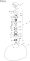
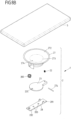
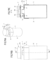
- FIG. 1A , 1B to 6A-6C show a first embodiment of a connecting device 1, which—in the illustrated embodiment—serves to attach an electronic device in the form of a camera 4 to a helmet 5 (e.g., a ski or bicycle helmet).
- the camera 4 can be detachably connected to an attachment surface 50 of the helmet 5 via the connecting device 1, so that, for example, video recordings can be made when the helmet 5 is in use.
- the connecting device 1 has a closure module 2 that can be attached to an attachment assembly 3 on the side of the helmet 5.
- the closure module 2 consists of a plurality of interacting parts and is fixed to the camera 4.
- the connection of the closure module 2 to the camera 4 can (likewise) be detachable in order to be able to use the connecting device 1, for example, on different electronic devices.
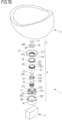
- the closure module 2 has a housing part 20 which is cylindrically shaped and is firmly connected via fastening points 201 to an adjusting element 23 which is received centrally in the housing part 20.
- the adjusting element 23 has a shaft 230 and a fastening point 231 arranged thereon, via which the adjusting element 23 is fixed to the housing part 20. At an end facing away from the bottom of the housing part 20, the adjusting element 23 has a head portion 232 that projects radially outward beyond the shaft 230.
- the housing part 20 and the adjustment element 23, which is connected to the housing part 20 in a rotationally fixed manner, are firmly connected to the camera 4.
- the section view according to Fig. 2C can be removed, the adjusting element 23 lies in a cylindrical cavity 253 of a cylinder part 25 such that the head section 232 is slidably guided on an inner surface 250 of the cylinder part 25.
- the cylinder part 25, which is cylindrical with a circular cross-section, is firmly connected to a guide part 21 which has an opening 212 through which the adjusting element 23 engages with its shaft 230.
- a collar 213 projects axially from a base of the guide part 21 facing the base of the housing part 20, into which collar the cylinder part 25 engages and via which the cylinder part 25 is firmly connected to the guide part 21 (for example by welding or gluing).
- the guide part 21 also has a cylindrical basic shape, with a cylindrical outer surface 210 that extends circumferentially around the cylinder part 25 accommodated within the guide part 21 and is thus arranged radially outside the cylinder part 25.
- a plurality of circumferentially offset, parallel, helical guideways 211 are formed on the outer surface 210. These guideways are formed as slotted guides in the outer surface 210 and engage with guide elements 202 in the form of pins on the housing part 20 (projecting radially inward from a outer surface 200 of the housing part 20).
- the housing part 20 Due to the engagement of the guide elements 202 of the housing part 20 in the guide tracks 211 of the guide part 21, the housing part 20 (and above it also the adjusting element 23) is positively guided on the guide part 21 about a rotation axis R, so that when the housing part 20 is rotated about the rotation axis R, the structural unit formed from the housing part 20 and the adjusting element 23 follows the helical guide tracks 211 and the adjusting element 23 is thereby moved axially within the cylinder part 25.
- the cylinder part 25 is firmly connected to a vacuum element 27 in the form of an elastic cup element 27, in that the cylinder part 25 engages in a collar 270 of the vacuum element 27 and is clamped to the vacuum element 27 via a circumferential tension spring 26.
- the vacuum element 27 is thus firmly connected, in particular also fluid-tight, to the cylinder part 20.
- the adjusting element 23 is prestressed by a prestressing element in the form of a compression spring 22 surrounding the shaft 230 relative to the guide part 21 and thus relative to the cylinder part 25 in the direction of the Fig. 2C shown starting position.
- a prestressing element in the form of a compression spring 22 surrounding the shaft 230 relative to the guide part 21 and thus relative to the cylinder part 25 in the direction of the Fig. 2C shown starting position.
- the head portion 232 of the adjusting element 23 thus comes to rest at an end of the cylinder part 25 that faces away from the guide part 21.
- the guide part 21 is retracted to its maximum extent into the housing part 20.
- the attachment surface 50 on the helmet 5 serves for attaching the vacuum element 27 in the form of a cup element.
- the attachment assembly 3 with an attachment part 30 and a magnetic element 31 received in a receiving opening 302 of the attachment part 30 is arranged on the attachment surface 50 of the helmet 5.
- the shutter module 2 for connecting the camera 4 to the helmet 5 is attached to this attachment assembly 3.
- the closure module 2 has a magnetic element 24, which is received in a receiving opening 234 of the adjustment element 23 and which, when the closure module 2 is attached to the attachment surface 50, interacts with the magnetic element 31 of the attachment assembly 3 in a magnetically attractive manner, so that the closure module 2 (with the camera 4 arranged thereon) is magnetically attracted to the attachment assembly 3 of the helmet 5.
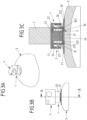
- a form-fitting section 233 in the form of a conical recess is formed, which, when the closure module 2 is attached, engages with an associated form-fitting section 300 in the form of a conical elevation on the attachment part 30, so that the closure module 2 is attached to the attachment assembly 3 of the helmet 5 in a defined manner.
- the positive locking between the positive locking sections 233, 300 serves to advantageously absorb transverse forces in the plane of the attachment surface 50 when the connecting device 1 is closed. Furthermore, the closure module 2 engages the attachment assembly 3 in a centered manner via the positive locking.
- the vacuum element 27 is elastically deformed at a cup-shaped edge section 272 projecting radially beyond the cylinder part 25, whereby air escapes from a space B formed between the vacuum element 27 and the attachment surface 50 and thus, when the closure module 2 is loaded, a suction vacuum acts between the vacuum element 27 and the attachment surface 50.
- pulse-like impact forces can be exerted on the connecting device 1 when using the Helmet 5 are absorbed and diverted so that the camera 4 is held securely and reliably on the helmet 5 even under impact loads.
- an engagement section 252 in the form of a toothing is formed, which, when the closure module 2 is attached to the attachment assembly 3, engages positively with a circumferential engagement section 301 in the form of a toothing on the attachment part 30, as can be seen from a synopsis of Fig. 2C and 3C and Fig. 1A and 1B can be seen.
- the cylinder part 25 and, above it, also the guide part 21 and the vacuum element 27 are fixed in a rotationally fixed manner to the attachment assembly 3 and thus to the helmet 5, so that torsional forces acting on the vacuum element 27 can also be effectively absorbed and dissipated.
- the camera 4 is thus rigidly attached to the helmet 5 via the connecting device 1.
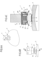
- the camera 4 and above it also the housing part 20 and the adjustment element 23 connected thereto are rotated in a direction of rotation D about the axis of rotation R relative to the cylinder part 25. Due to the engagement of the engagement sections 252, 301 on the side of the cylinder part 25 and the attachment part 30, it is ensured that the cylinder part 23 cannot rotate during this twisting movement and thus the adjustment element 23 is moved within the cylindrical cavity 253 of the cylinder part 25.
- the adjusting element 23 is adjusted axially along the rotation axis R within the cylinder part 25 and thus, as can be seen from Fig. 4C visible, from the attachment part 30.
- This causes, on the one hand, that the magnetic elements 24, 31 are moved away from each other, so that the magnetic attraction between the magnetic elements 24, 31 is weakened.
- this causes the head section 232 to slide within the cavity 253 and to sweep over a flow opening 251 in the wall of the cylinder part 25, so that an air flow F can flow into the space B through the flow opening 251 and a negative pressure in the space B is thus equalized.
- the helical guide of the housing part 20 on the guide part 21 allows for easy adjustment of the adjustment element 23. Releasing the connecting device 1 can thus be haptically pleasant and comfortable for a user, while the connecting device 1 is highly resilient in the connected position.
- the adjustment element 23 returns to its original position due to the preloading effect of the preloading element 22 in the form of a compression spring, rotating the cylinder part 25 and the adjustment element 23 relative to each other.
- the closure module 2 can thus be reattached to the attachment assembly 3 if desired.
- a negative pressure between the vacuum element 27 and the contact surface 50 is particularly effective in the case of sudden, short-term loads.
- a load e.g., tensile load
- a force acts in the direction of enlarging the space B, which leads to a negative pressure in this space B.
- the vacuum element 27, which forms a flat seal against the contact surface 50, can thus effectively absorb particularly sudden loads.
- the magnetic elements 24, 31, additionally support the attachment of the closure module 2 and the attachment assembly 3 to each other, pressing the vacuum element 27 against the attachment surface 50.
- the connecting device 1 can also ensure emergency tearing off in the case of larger, longer-lasting loads. For example, if a (predetermined) limit force, the camera 4 can be torn off the helmet 5, releasing the vacuum element 27 from the attachment surface 50.
- the vacuum element 27 and the vacuum force provided on the vacuum element 27 can be dimensioned accordingly.
- the connecting device 1 serves to attach a mobile phone 5 or another electronic device (for example, a navigation device), for example, in a vehicle, for example on the dashboard or on the windshield of the vehicle.
- the attachment assembly 3 is arranged according to the invention on a housing surface of the mobile phone 5 or the other electronic device serving as an attachment surface 50, while the closure module 2 can be arranged on the vehicle, for example by at least partially integrating the closure module 2 into a dashboard and thus recessing it.
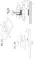
- a closure module 2 is to be attached to an attachment component 50 in the form of an attachment surface on an electronic device 5 or another assembly.
- the closure module 2 has a vacuum element 27, which has a flexible edge portion 272 and is to be connected to the attachment component 50 in the form of the attachment surface on the assembly 5 by means of the flexible edge portion 272, subjected to elastic deformation to provide a vacuum effect.
- the flexible edge portion 272 extends circumferentially as a cup element around a body 273, on which a flow opening 274 is formed and on which an adjustment element 23 in the form of a flap element is articulated via bearing elements 275 and an axle element 276.
- An actuating element 28 is also arranged on the axle element 276, which interacts with the adjusting element 23 in the form of the flap element in order to actuate the adjusting element 23 to release the closure module 2 from the attachment component 50.
- actuating element 28 is guided by a spring element 280 in the form of a tension spring in the direction of Fig. 9A-9C shown
- the adjusting element 23 is spring-loaded into the initial position by a pre-tensioning element 22 in the form of a compression spring.
- Fastening points 283 in the form of, for example, screw holes are provided on the actuating element 28, via which the actuating element 28 can be connected to an associated, further assembly.
- the actuating element 28 can be secured to a vehicle, for example to a dashboard of a motor vehicle, in order to (removably) secure an assembly 5, for example, an electronic device in the form of a mobile phone or the like, to the vehicle.
- the adjustment element 23 is adjusted by actuating the actuating element 28, so that the flow opening 274 is released and an air flow can flow through the flow opening 274 between the vacuum element 27 and the attachment component 50, as shown in Fig. 10A-10C is shown.
- a negative pressure effect between the negative pressure element 27 and the attachment component 50 is thus eliminated, so that no holding forces act between the closure module 2 and the attachment component 50 (anymore).
- the actuating element 28 is tilted about the axis element 276 relative to the vacuum element 27, as can be seen from Fig. 10A-10C can be seen.
- the actuating element 28 acts on the adjusting element 23 with a section 281 remote from the head end 282 and also pivots the adjusting element 23 about the axis element 276.
- the adjusting element 23 is thus moved—indirectly via the actuating element 28—out of its closed position and releases the flow opening 274, so that the closure module 2 can be released from the attachment component 50.
- the spring element 280 is tensioned, as can be seen from Fig. 10A-10C can be seen.
- the pre-tensioning element 22 is tensioned under pressure.
- the actuating element 28 and the adjusting element 23 return to their respective starting positions due to the spring action, shown in Fig. 9A-9C , so that when the actuating element 28 is not actuated, the flow opening 274 is closed and the vacuum element 27 can thus be attached to an attachment component 50 to reconnect the closure module 2.
- Magnetic elements can be arranged on the one hand on the closure module 2 and on the other hand on the attachment component 50 in order to magnetically support the attachment of the closure module 2 to the attachment component 50.
- the connecting device 1 can also be non-magnetic and hold the closure module 2 to the attachment component 50 solely due to the negative pressure effect.
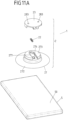
- an adjusting element 23 is slidably arranged on a vacuum element 27 of a closure module 2 of a connecting device 1.
- the vacuum element 27 in turn has a flexible, elastically deformable edge section 272 in the form of a cup element, with which the vacuum element 27 can be attached to a flat attachment component 50 of an assembly 5 in order to be in the attached position ( Fig. 12A-12C ) to hold the closure module 2 on the attachment component 50 due to a negative pressure effect.
- an adjusting element 23 is displaceably guided on a body 273 of the vacuum element 27 along a guide direction extending transversely to an attachment direction A, in that the adjusting element 23 engages with a guide piece 236 in an associated guide device 277 on the body 273 of the vacuum element 27.
- the adjusting element 23 closes a flow opening 274 in the body 273 with a closing element 235 in the form of a pin, so that a negative pressure effect between the negative pressure element 27 and the attachment component 50 for holding the closure module 2 on the attachment component 50 exists when the closure module 2 is attached to the attachment component 50.
- a negative pressure effect between the negative pressure element 27 and the attachment component 50 for holding the closure module 2 on the attachment component 50 exists when the closure module 2 is attached to the attachment component 50.
- the flow opening 274 is closed, an inflow of air between the vacuum element 27 and the attachment component 50 via the flow opening 274 is prevented.
- the adjustment element 23 can be moved transversely to the attachment direction A on the body 273 of the vacuum element 27, as shown in Fig. 13A-13C is shown.
- a prestressing element in the form of a compression spring acting between the adjusting element 23 and the vacuum element 27 is tensioned under pressure, and the flow opening 274 is released so that an air flow can flow between the vacuum element 27 and the attachment component 50 and a vacuum effect between the vacuum element 27 and the attachment component 50 is thus canceled.
- the adjusting element 23 After completion of the actuation, the adjusting element 23 is automatically returned to the starting position according to the pressure effect of the pre-tensioning element 22.
- Fig. 12A-12C reset, so that in the initial position when the adjusting element 23 is not actuated, the flow opening 274 is again closed and the closure module 2 can thus be attached again to an associated attachment component 50 of an assembly 5.
- the adjusting element 23 has fastening points 283 via which an associated assembly can be fastened to the adjusting element 23.
- the adjusting element 23 is thus actuated by a relative movement between the assembly connected to the adjusting element 23 and the assembly 5 to which the closure module 2 is attached. For example, a user can grip the assembly 5 in order to move the adjusting element 23 toward the vacuum element 27 and thus detach the assembly 5 from the closure module 2.
- the assembly 5 can, for example, be an electronic device in the form of a mobile phone or the like.
- the adjustment element 23, on the other hand, can be fixed to a vehicle, for example, to a dashboard of a motor vehicle, so that the assembly 5 can be releasably attached to the vehicle via the connecting device 1.
- the vacuum element is designed as an elastic cup element.
- this is not mandatory.
- rigid, non-elastic elements cooperate to create a negative pressure and thus to provide a holding force, although this is not within the scope of the present invention.
- the connecting device 1 has a closure module 2 that can be attached to an assembly 5.
- the closure module 2 of the connecting device 1 which is rigid and inelastic, can, for example, be precisely inserted into an attachment component 50 in the form of an opening 500 formed in the assembly 5, so that the cylinder part 23 is received in a substantially fluid-tight manner within the opening 500.
- a negative pressure is created between the cylinder part 25 and the walls of the opening 500, so that the closure module 2 is fixed to the assembly 5.
- An adjusting element 23 adjustable within the cylinder part 25 can be adjusted in a manner analogous to that described above in order to release the connecting device 1 by opening a flow path between a flow opening 251 in the cylinder part 25 and a space formed between the cylinder part 25 and the walls of the opening 500, so that air can flow into the space and the cylinder part 25 can thus be removed from the opening 500.
- the cylinder part 25 can be inserted precisely into the opening 500, thus creating a fluid-tight transition between the cylinder part 25 and the walls of the opening 500.
- the outer shape of the cylinder part 25 can be circular-cylindrical, although the cylinder part 25 can also have a different outer shape, for example, a polygonal outer shape or any other cross-sectional shape.
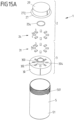
- Fig. 15A , 15B to 19A-19C show an embodiment of a container in the form of a drinking bottle, in which a container body 51 of an assembly 5 can be connected to a lid 29 in order to close the container body 51.
- the lid 29 is part of a closure module 2 of a connecting device 1, via which the lid 29 can be firmly but detachably connected to the container body 51.
- the connecting device 1 is formed by the closure module 2, of which the lid 29 is a component, and an attachment assembly 3 with an attachment part 30, which is to be connected to the container body 51 via a thread 501.
- the attachment part 30 has a form-fitting section 300 in the form of a protruding pin piece, which has a central opening through which a user can drink from the drinking bottle, for example, when the lid 29 is removed.
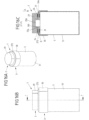
- the cover 29 of the closure module 2 forms, together with a flexible, circumferential edge section 272, a vacuum element 27 which can be attached to the attachment part 30 of the attachment assembly 3 in an attachment direction A and in the attached position ( Fig. 17A-17C ) is held on the attachment part 30 under the effect of negative pressure.
- an engagement opening 256 is formed, into which the form-fitting section 300 of the attachment part 30 engages when the closure module 2 is attached.
- a seal 254 in the form of an O-ring is arranged on the inner surface of the engagement opening 256, which seals off a transition between the lid 29 and the form-fitting section 300 in a fluid-tight, in particular moisture-tight, manner, so that liquid cannot penetrate out of the container 50 when the lid 29 is attached to the container body 51.
- the attachment part 30 On a surface 304 facing the cover 21, the attachment part 30 has receiving openings 302 into which magnetic elements 31 are inserted and connected to the attachment part 30. Likewise, receiving openings 255 are formed on the inside of the cover 29, into which magnetic elements 24 are inserted and thus held on the cover 29.
- the magnetic elements 31 on the attachment part 30, on the one hand, and the magnetic elements 24 on the cover 29, on the other hand, are evenly distributed and alternately polarized, viewed circumferentially around the attachment direction A.
- a magnetic element 31 of the attachment part 30 thus points with a north pole N toward the cover 29, while adjacent magnetic elements 31 each point with a south pole S toward the cover 29 and then again follow north poles N.
- a magnetic element 24 of the cover 29 points with a south pole S toward the attachment part 30, while adjacent magnetic elements 24 each point with a north pole N toward the attachment part 30 and then again follow south poles S.
- the lid 29 can be rotated along an opening direction O, along which the lid 29 can be rotated about a rotation axis R defined by the engagement of the form-fitting section 300 in the engagement opening 256 relative to the attachment part 30, whereby the magnetic elements 24, 31 with like-like poles are brought closer together and thus a magnetic repulsion is created between the magnetic elements 24, 31.
- This magnetic repulsion can weaken or even exceed the negative pressure effect between the lid 29 and the attachment part 30, so that the lid 29 can be easily released from the attachment part 30 in the opposite direction to the attachment direction A, and the drinking bottle can thus be opened.
- This is in the transition from Fig. 18A-18C towards Fig. 19A-19C
- This rotation can also open a flow opening.
- a connection of a lid 29 with a container 5 of the type described is not only conceivable and possible with a drinking bottle, for example for use on a bicycle, but can also be used with completely different, arbitrary containers that can be closed with a lid.
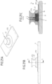
- FIG. 20A-20C and 21A-21C show an embodiment of a connecting device 1, which has a closure module 2 with a vacuum element 27, which can be attached in an attachment direction A to an attachment part 30 of an attachment assembly 3 connected to an assembly 5.
- a further assembly can be connected to the vacuum element 27, so that the assembly 5, for example an electronic device in the form of a mobile phone, can be arranged on the further assembly via the connecting device 1.
- the vacuum element 27 has a flexible edge portion 272 in the form of a cup element. Furthermore, a magnetic element 24 is arranged on a body 273, which magnetically interacts with a magnetic element 31 on the attachment part 30 of the attachment assembly 3 when the closure module 2 is attached to the attachment assembly 3, thus magnetically supporting the attachment of the closure module 2 to the attachment assembly 3.
- the closure module 2 is released from the attachment assembly 3 by pulling or tilting the vacuum element 27.
- electrical contact elements 6 are arranged on the closure module 2, which, when the closure module 2 is attached to the attachment assembly 3, make electrical contact with associated counter-contact elements 7 on the side of the attachment assembly 3, as can be seen from Fig. 20C in conjunction with Fig. 21C can be seen. Via the contact elements 6 and the counter-contact elements 7, an electrical connection can thus be established between the assembly 5 assigned to the attachment assembly 30 and an assembly assigned to the closure module 2, for example in order to provide an electrical supply or a data connection.
- the electrical contact elements 6 have contact pins 61, which are elastically supported on the body 273 of the vacuum element 27 via spring elements 62 and are connected to electrical lines 60.
- the counter-contact elements 7, on the other hand, can be designed, for example, as contact pads or the like on an upper side of the attachment part 30 facing the vacuum element 27, so that in a position where the closure module 2 ( Fig. 21A-21C ) the contact elements 6 make electrical contact with the mating contact elements 7.
- Fig. 22A-22C to 24A-24C The embodiment shown is identical to that shown in Fig. 1A , 1B to 6A-6C described embodiment, wherein additionally on the closure module 2 on the one hand and on the attachment assembly 3 on the other hand electrical contact elements 6 are arranged, which when the closure module ( Fig. 24A-24C ) can electrically contact one another and thus establish an electrical connection between the modules assigned to the connecting device 1, for example for an electrical supply of a module 5, for example an electronic device in the form of a mobile phone, or for providing a data connection.
Landscapes
- Engineering & Computer Science (AREA)
- General Engineering & Computer Science (AREA)
- Mechanical Engineering (AREA)
- Telephone Set Structure (AREA)
- Hooks, Suction Cups, And Attachment By Adhesive Means (AREA)
- Helmets And Other Head Coverings (AREA)
- Connection Of Plates (AREA)
- Fittings On The Vehicle Exterior For Carrying Loads, And Devices For Holding Or Mounting Articles (AREA)
Claims (2)
- Dispositif électronique (5), en particulier caméra ou téléphone portable, comprenantun dispositif de connexion (1) pour connecter de manière amovible le dispositif électronique (5) à un autre ensemble,dans lequel le dispositif de connexion (1) comprend un module de fermeture (2) avec un élément de dépression (27), qui peut être connecté dans une direction de rattachement (A) à un composant de rattachement (50) qui est formé par une surface de boîtier (50) du dispositif électronique (5) servant de surface de rattachement (50), pour connecter le dispositif électronique (5) à l'autre ensemble et qui interagit dans une position connectée avec le composant de rattachement (50) de telle sorte que, lorsque le module de fermeture (2) et le composant de rattachement (50) sont chargés l'un par rapport à l'autre dans le sens opposé à la direction de rattachement (A), l'élément de dépression (27) et le composant de rattachement (50) sont maintenus l'un contre l'autre en raison d'une action de dépression entre l'élément de dépression (27) et le composant de rattachement (50),dans lequel le module de fermeture (2) présente un premier élément magnétique (24) pour soutenir magnétiquement la connexion du dispositif électronique (5) avec l'autre ensemble,dans lequel l'élément de dépression (27) est formé par un élément de coupelle élastique au moins par sections,dans lequel l'élément de dépression (27) peut être rattaché dans la direction de rattachement (A) à une partie de rattachement (30) d'un ensemble de rattachement (3) connecté avec le dispositif électronique (5) et agencé au composant de rattachement,dans lequel un deuxième élément magnétique (31) est agencé sur la partie de rattachement (30) de l'ensemble de rattachement (3) et, lorsque le module de fermeture (2) est rattaché à l'ensemble de rattachement (3), interagit par attraction magnétique avec le premier élément magnétique (24) agencé sur l'élément de dépression (27) ou un élément connecté avec l'élément de dépression (27).
- Dispositif électronique selon la revendication 1, caractérisé en ce que le module de fermeture (2) comprend au moins un élément de contact électrique (6) destiné à entrer en contact électrique avec au moins un élément de contact complémentaire (7) associé au composant de rattachement (50) dans la position connectée.
Priority Applications (1)
| Application Number | Priority Date | Filing Date | Title |
|---|---|---|---|
| EP21191917.0A EP3929451B1 (fr) | 2017-11-06 | 2018-11-05 | Ensemble de telephone portable et de dispositif de liaison |
Applications Claiming Priority (2)
| Application Number | Priority Date | Filing Date | Title |
|---|---|---|---|
| DE102017125846.9A DE102017125846A1 (de) | 2017-11-06 | 2017-11-06 | Verbindungsvorrichtung zum lösbaren Verbinden zweier Baugruppen |
| PCT/EP2018/080101 WO2019086648A2 (fr) | 2017-11-06 | 2018-11-05 | Dispositif de raccordement pour raccorder deux sous-ensembles de manière amovible |
Related Child Applications (2)
| Application Number | Title | Priority Date | Filing Date |
|---|---|---|---|
| EP21191917.0A Division EP3929451B1 (fr) | 2017-11-06 | 2018-11-05 | Ensemble de telephone portable et de dispositif de liaison |
| EP21191917.0A Division-Into EP3929451B1 (fr) | 2017-11-06 | 2018-11-05 | Ensemble de telephone portable et de dispositif de liaison |
Publications (2)
| Publication Number | Publication Date |
|---|---|
| EP3707397A2 EP3707397A2 (fr) | 2020-09-16 |
| EP3707397B1 true EP3707397B1 (fr) | 2025-04-30 |
Family
ID=64362486
Family Applications (2)
| Application Number | Title | Priority Date | Filing Date |
|---|---|---|---|
| EP21191917.0A Active EP3929451B1 (fr) | 2017-11-06 | 2018-11-05 | Ensemble de telephone portable et de dispositif de liaison |
| EP18804526.4A Active EP3707397B1 (fr) | 2017-11-06 | 2018-11-05 | Dispositif de raccordement pour raccorder deux sous-ensembles de manière amovible |
Family Applications Before (1)
| Application Number | Title | Priority Date | Filing Date |
|---|---|---|---|
| EP21191917.0A Active EP3929451B1 (fr) | 2017-11-06 | 2018-11-05 | Ensemble de telephone portable et de dispositif de liaison |
Country Status (7)
| Country | Link |
|---|---|
| US (1) | US11739786B2 (fr) |
| EP (2) | EP3929451B1 (fr) |
| JP (1) | JP7411416B2 (fr) |
| KR (1) | KR102731532B1 (fr) |
| CN (3) | CN110719998B (fr) |
| DE (1) | DE102017125846A1 (fr) |
| WO (1) | WO2019086648A2 (fr) |
Families Citing this family (22)
| Publication number | Priority date | Publication date | Assignee | Title |
|---|---|---|---|---|
| EP3682126B1 (fr) * | 2017-09-11 | 2023-06-28 | Elite Group International AB | Dispositif de connexion magnétique et mécanique |
| DE102017125846A1 (de) * | 2017-11-06 | 2019-05-09 | Fidlock Gmbh | Verbindungsvorrichtung zum lösbaren Verbinden zweier Baugruppen |
| CN110303992B (zh) * | 2019-06-21 | 2020-07-07 | 深圳市晶祥鑫电子有限公司 | 一种吸附装置 |
| DE102019123714A1 (de) | 2019-09-04 | 2021-03-04 | Fidlock Gmbh | Verbindungsvorrichtung zum lösbaren Verbinden zweier Baugruppen |
| US11754101B2 (en) * | 2020-02-13 | 2023-09-12 | Scott Snedeker | Magnetic standoff system |
| CN114829791B (zh) * | 2020-06-26 | 2025-01-07 | 费得洛克有限公司 | 用于可脱开地连接两个组件的连接设备 |
| DE102020207983A1 (de) | 2020-06-26 | 2021-12-30 | Fidlock Gmbh | Verbindungsvorrichtung zum lösbaren Verbinden zweier Baugruppen |
| DE102020210432B4 (de) | 2020-08-17 | 2026-05-07 | Fidlock Gmbh | Verbindungsvorrichtung zum lösbaren Verbinden zweier Baugruppen |
| EP4348068B1 (fr) * | 2021-06-03 | 2026-03-11 | Fidlock GmbH | Dispositif de raccordement comprenant un élément de vide |
| DE202021103028U1 (de) | 2021-06-03 | 2021-08-16 | Fidlock Gmbh | Verbindungsvorrichtung mit einem Unterdruckelement |
| US20230108638A1 (en) * | 2021-10-04 | 2023-04-06 | Bunn-O-Matic Corporation | Magnetic light cord for use with a beverage making and dispensing machine |
| US12108824B2 (en) * | 2021-10-22 | 2024-10-08 | Cookie Composites Group Pty Ltd. | Helmet provided with an accessory fastening assembly |
| DE102021130474A1 (de) | 2021-11-22 | 2023-05-25 | Dräger Safety AG & Co. KGaA | Helmkamerasystem, Befestigungsvorrichtung, Helmsystem und Kamerasystem |
| US20230228288A1 (en) * | 2022-01-19 | 2023-07-20 | Jin Sun Gee Plastics Co., Ltd. | Tray assembly |
| EP4514658A4 (fr) * | 2022-04-25 | 2026-03-25 | Heath Consultants Incorporated | Systèmes et procédés de montage libérable à haute fiabilité et de haute précision |
| KR102479727B1 (ko) * | 2022-07-21 | 2022-12-20 | 조성재 | 후방카메라를 구비한 모자 |
| CN120077633A (zh) * | 2022-08-25 | 2025-05-30 | 磁力机械有限责任公司 | 可拆卸的磁性安装系统、装置和方法 |
| US12512244B2 (en) | 2022-08-25 | 2025-12-30 | Magnetic Mechanisms L.L.C. | Detachable magnetic holding device |
| WO2024044322A1 (fr) | 2022-08-25 | 2024-02-29 | Magnetic Mechanisms L.L.C. | Crochet magnétique détachable sans levier |
| CN115649069B (zh) * | 2022-12-14 | 2023-03-03 | 四川省公路规划勘察设计研究院有限公司 | 车载激光点云扫描仪 |
| CN116006844A (zh) * | 2022-12-16 | 2023-04-25 | 深圳市蓝禾科技有限公司 | 电子设备支架 |
| US20240389696A1 (en) * | 2023-05-24 | 2024-11-28 | Tanya Parisia | Hair extension mount |
Family Cites Families (48)
| Publication number | Priority date | Publication date | Assignee | Title |
|---|---|---|---|---|
| DE2064615C3 (de) * | 1969-12-30 | 1973-11-08 | George Friis Galway Keeleric (Grossbritannien) | Verschlußvorrichtung fur einen Behalter |
| JPS4938865U (fr) | 1972-07-17 | 1974-04-05 | ||
| JPS5196176U (fr) | 1975-01-31 | 1976-08-02 | ||
| US4058335A (en) | 1976-01-27 | 1977-11-15 | Seiji Abe | Magnetic sheet the magnetic attraction of which is strengthened |
| US4112941A (en) * | 1977-01-06 | 1978-09-12 | Minnesota Mining And Manufacturing Company | Electrode and magnetic connector assembly |
| US4402560A (en) * | 1981-07-13 | 1983-09-06 | Swainbank Sheila O | Conductive wrist strap |
| JPS59177819U (ja) * | 1983-05-17 | 1984-11-28 | 三洋電機株式会社 | 吸着装置 |
| US4755144A (en) * | 1986-02-24 | 1988-07-05 | Plastic Systems, Inc. | Static grounding buckle having continuous contact |
| US4662695A (en) * | 1986-02-24 | 1987-05-05 | Plastic Systems, Inc. | Static grounding buckle |
| US5076527A (en) * | 1990-09-10 | 1991-12-31 | Yung Huei Lan | Sucking on device which is easily to be lifted but is not easily getting overturned |
| US5192043A (en) | 1991-12-11 | 1993-03-09 | Yen C Fa | Magnetic rubber suction disc |
| JP2884135B2 (ja) | 1994-06-27 | 1999-04-19 | リーマン株式会社 | 吸着式貨物固定装置の固定板 |
| DE19512335C1 (de) * | 1995-04-01 | 1996-08-29 | Fritsch Klaus Dieter | Elektromechanische Verbindungsvorrichtung |
| JP2000104724A (ja) * | 1998-09-25 | 2000-04-11 | Sophia Sutatsufu Kk | 吸着盤 |
| KR200250966Y1 (ko) * | 2001-07-27 | 2001-11-22 | 학 보 심 | 자성을 이용한 흡착 패드 |
| US6910911B2 (en) * | 2002-06-27 | 2005-06-28 | Vocollect, Inc. | Break-away electrical connector |
| US7775801B2 (en) * | 2005-01-05 | 2010-08-17 | Microsoft Corporation | Device interfaces with non-mechanical securement mechanisms |
| JP2007068828A (ja) * | 2005-09-08 | 2007-03-22 | Motoyuki Fujiwara | 物品支持具 |
| US7351066B2 (en) * | 2005-09-26 | 2008-04-01 | Apple Computer, Inc. | Electromagnetic connector for electronic device |
| DE102006062692B4 (de) * | 2006-02-06 | 2008-08-21 | J. Schmalz Gmbh | Sauggreifer |
| KR200425041Y1 (ko) * | 2006-06-20 | 2006-08-28 | 정순호 | 차량용 모니터 거치대 |
| PL2436280T3 (pl) * | 2006-07-12 | 2017-12-29 | Fidlock Gmbh | Mechaniczno-magnetyczna konstrukcja łącząca |
| CN200959266Y (zh) * | 2006-08-10 | 2007-10-10 | 特腾高频股份有限公司 | 磁性吸盘及使用该磁性吸盘的天线 |
| US7798831B2 (en) * | 2007-01-06 | 2010-09-21 | Apple Inc. | Connector assemblies |
| KR20090075435A (ko) * | 2008-01-04 | 2009-07-08 | 주식회사 대우일렉트로닉스 | 거치대의 고정구조 |
| CN101504029B (zh) * | 2008-02-05 | 2010-12-22 | 昭通科技股份有限公司 | 固定座吸附装置 |
| CN201177001Y (zh) * | 2008-03-14 | 2009-01-07 | 宁波双友塑料制品有限公司 | 一种真空吸盘 |
| KR20100009777U (ko) * | 2009-03-26 | 2010-10-06 | 정형두 | 안전등이 구비된 안전모 |
| DE202009010961U1 (de) * | 2009-08-13 | 2009-12-10 | LIN, Kun-shu | Abdichtbarer Behälter |
| DE102010044144B3 (de) * | 2010-11-18 | 2012-05-31 | Fidlock Gmbh | Verschlussvorrichtung |
| GB201103103D0 (en) | 2011-02-23 | 2011-04-06 | Givaudan Sa | Organic compounds |
| US9482255B2 (en) | 2011-09-21 | 2016-11-01 | Bal Seal Engineering, Inc. | Multi-latching mechanisms and related methods |
| US8925881B2 (en) * | 2012-05-28 | 2015-01-06 | Anna Genevieve Diatzikis | Magnetic mount |
| JP2014173709A (ja) * | 2013-03-13 | 2014-09-22 | Ricoh Co Ltd | 吸盤及び電子機器 |
| KR101451277B1 (ko) * | 2013-05-23 | 2014-10-15 | 송순영 | 헬멧 장착용 거치대 |
| CN203604414U (zh) * | 2013-12-17 | 2014-05-21 | 卢英姿 | 真空吸附式吸盘 |
| CN203932555U (zh) * | 2014-05-05 | 2014-11-05 | 中兴通讯股份有限公司 | 一种吸附器及连接器 |
| US9729185B2 (en) * | 2015-03-06 | 2017-08-08 | Wood Brothers Steel Stamping Company | Self-centering and adjustable mount |
| GB201506418D0 (en) * | 2015-04-15 | 2015-05-27 | Connectors Ltd Ab | Connector assembly |
| CN204646966U (zh) * | 2015-06-03 | 2015-09-16 | 马鞍山聚力科技有限公司 | 一种负压磁铁吸盘装置 |
| US9814332B2 (en) | 2015-06-29 | 2017-11-14 | Israel Harry Zimmerman | Anchoring device with directional release and attachment capability and protection against inadvertent release |
| US9848071B2 (en) * | 2015-08-28 | 2017-12-19 | Jean-Michel Andre Thiers | Rotatable electrical connector |
| CN105266268A (zh) * | 2015-10-22 | 2016-01-27 | 孔远萍 | 一种防滑鞋 |
| US9521919B1 (en) * | 2016-04-26 | 2016-12-20 | Yvette Reyes | Self-stabilizing article holder |
| US10085080B2 (en) * | 2016-09-06 | 2018-09-25 | Apple Inc. | Earphone assemblies with multiple subassembly housings |
| CN106505363B (zh) * | 2016-12-23 | 2019-11-26 | 深圳市泰科汉泽精密电子有限公司 | 磁性电极纽扣 |
| DE102017125846A1 (de) * | 2017-11-06 | 2019-05-09 | Fidlock Gmbh | Verbindungsvorrichtung zum lösbaren Verbinden zweier Baugruppen |
| CN109995399B (zh) * | 2017-12-29 | 2021-08-20 | 富鼎精密工业(郑州)有限公司 | 连接器及其组合 |
-
2017
- 2017-11-06 DE DE102017125846.9A patent/DE102017125846A1/de not_active Withdrawn
-
2018
- 2018-11-05 JP JP2019571622A patent/JP7411416B2/ja active Active
- 2018-11-05 CN CN201880037750.2A patent/CN110719998B/zh active Active
- 2018-11-05 KR KR1020197035894A patent/KR102731532B1/ko active Active
- 2018-11-05 WO PCT/EP2018/080101 patent/WO2019086648A2/fr not_active Ceased
- 2018-11-05 EP EP21191917.0A patent/EP3929451B1/fr active Active
- 2018-11-05 US US16/761,638 patent/US11739786B2/en active Active
- 2018-11-05 CN CN202311290813.4A patent/CN117536974A/zh active Pending
- 2018-11-05 CN CN202111031222.6A patent/CN113864320B/zh active Active
- 2018-11-05 EP EP18804526.4A patent/EP3707397B1/fr active Active
Also Published As
| Publication number | Publication date |
|---|---|
| EP3707397A2 (fr) | 2020-09-16 |
| DE102017125846A1 (de) | 2019-05-09 |
| EP3929451A1 (fr) | 2021-12-29 |
| EP3929451B1 (fr) | 2025-02-19 |
| US11739786B2 (en) | 2023-08-29 |
| CN113864320A (zh) | 2021-12-31 |
| KR20200100527A (ko) | 2020-08-26 |
| CN110719998A (zh) | 2020-01-21 |
| WO2019086648A3 (fr) | 2019-07-11 |
| JP2021501835A (ja) | 2021-01-21 |
| CN110719998B (zh) | 2023-09-29 |
| WO2019086648A2 (fr) | 2019-05-09 |
| JP7411416B2 (ja) | 2024-01-11 |
| CN113864320B (zh) | 2024-02-13 |
| US20210180642A1 (en) | 2021-06-17 |
| CN117536974A (zh) | 2024-02-09 |
| KR102731532B1 (ko) | 2024-11-15 |
Similar Documents
| Publication | Publication Date | Title |
|---|---|---|
| EP3707397B1 (fr) | Dispositif de raccordement pour raccorder deux sous-ensembles de manière amovible | |
| DE102013000557B4 (de) | Magnetische Schließvorrichtung für Behältnisse, insbesondere für Weichgepäckstücke | |
| DE102019123714A1 (de) | Verbindungsvorrichtung zum lösbaren Verbinden zweier Baugruppen | |
| DE102014101952B4 (de) | Steckverbinderteil mit einem Rastelement | |
| EP3713781B1 (fr) | Dispositif de détection pour système d'attelage de véhicule tracteur | |
| DE102007017588A1 (de) | Blockiervorrichtung mit feldsteuerbarer Flüssigkeit | |
| EP2497744A2 (fr) | Outil de fermeture | |
| DE102012020710A1 (de) | Kraftfahrzeug mit wenigstens einer Ladeeinrichtung zur Aufladung wenigstens eines elektrischen Energiespeichers | |
| DE102012011951A1 (de) | Verriegelungsvorrichtung und Fahrzeugsitz | |
| DE102013112289A1 (de) | Abdeckvorrichtung für einen Steckverbinder | |
| DE102014103181A1 (de) | Verschlussvorrichtung mit Zustandsanzeige | |
| DE102016000909B3 (de) | Deckelvorrichtung, Ablagefach mit Deckelvorrichtung und Werkzeug zur Montage | |
| DE102017105522B4 (de) | Abstimmbarer Halter für Verschlusseinrichtungen von Luftfahrzeug-Abteilen | |
| DE102011053607A1 (de) | Halter für ein elektronisches Gerät | |
| DE102013015490A1 (de) | Haltevorrichtung zum Befestigen eines elektronischen Gerätes in einem Kraftfahrzeug | |
| EP3800360B1 (fr) | Dispositif de verrouillage avec des parts de verrouillage qui s'attachent | |
| DE102009034055A1 (de) | Drehmomentbegrenztes Kupplungselement sowie Verfahren zum drehmomentbegrenzten Kuppeln | |
| DE102020005568A1 (de) | Getränkebehältervorrichtung für ein Fahrzeug zum Halten eines Getränkebehälters, sowie dazugehöriges Verfahren | |
| EP4431785A1 (fr) | Système de retenue et procédé de fixation amovible d'un objet plat sur un objet et dispositif de retenue destiné à être utilisé dans un tel système de retenue | |
| EP1581400B1 (fr) | Instrument d'ecriture | |
| DE102014017353B4 (de) | Karosseriestruktur für ein Cabriolet mit einem Verdeckkastendeckel | |
| DE102012204185B3 (de) | Hörinstrument-Batterielade mit Verriegelung | |
| WO2022253586A1 (fr) | Dispositif de raccordement comprenant un élément de vide | |
| DE102021130404A1 (de) | Dichte Vorrichtung, die Zugang zu einem Gehäuse bietet, sowie entsprechendes System zur dichten Verbindung zwischen zwei Gehäusen | |
| DE10346093B4 (de) | In einen Einbau-Rahmen einsetzbares Spann-Modul sowie Kombination aus einem Einbau-Rahmen und einem Spann-Modul zur mechanischen Sicherung von entfernbaren Gebrauchs-Gegenständen |
Legal Events
| Date | Code | Title | Description |
|---|---|---|---|
| STAA | Information on the status of an ep patent application or granted ep patent |
Free format text: STATUS: UNKNOWN |
|
| STAA | Information on the status of an ep patent application or granted ep patent |
Free format text: STATUS: THE INTERNATIONAL PUBLICATION HAS BEEN MADE |
|
| PUAI | Public reference made under article 153(3) epc to a published international application that has entered the european phase |
Free format text: ORIGINAL CODE: 0009012 |
|
| STAA | Information on the status of an ep patent application or granted ep patent |
Free format text: STATUS: REQUEST FOR EXAMINATION WAS MADE |
|
| 17P | Request for examination filed |
Effective date: 20200427 |
|
| AK | Designated contracting states |
Kind code of ref document: A2 Designated state(s): AL AT BE BG CH CY CZ DE DK EE ES FI FR GB GR HR HU IE IS IT LI LT LU LV MC MK MT NL NO PL PT RO RS SE SI SK SM TR |
|
| AX | Request for extension of the european patent |
Extension state: BA ME |
|
| RIN1 | Information on inventor provided before grant (corrected) |
Inventor name: BOTKUS, BREIDO Inventor name: FIEDLER, JOACHIM Inventor name: BLECKAT, BJOERN |
|
| DAV | Request for validation of the european patent (deleted) | ||
| DAX | Request for extension of the european patent (deleted) | ||
| STAA | Information on the status of an ep patent application or granted ep patent |
Free format text: STATUS: EXAMINATION IS IN PROGRESS |
|
| 17Q | First examination report despatched |
Effective date: 20220322 |
|
| GRAP | Despatch of communication of intention to grant a patent |
Free format text: ORIGINAL CODE: EPIDOSNIGR1 |
|
| STAA | Information on the status of an ep patent application or granted ep patent |
Free format text: STATUS: GRANT OF PATENT IS INTENDED |
|
| INTG | Intention to grant announced |
Effective date: 20241204 |
|
| P01 | Opt-out of the competence of the unified patent court (upc) registered |
Free format text: CASE NUMBER: APP_6765/2025 Effective date: 20250210 |
|
| GRAS | Grant fee paid |
Free format text: ORIGINAL CODE: EPIDOSNIGR3 |
|
| GRAA | (expected) grant |
Free format text: ORIGINAL CODE: 0009210 |
|
| STAA | Information on the status of an ep patent application or granted ep patent |
Free format text: STATUS: THE PATENT HAS BEEN GRANTED |
|
| AK | Designated contracting states |
Kind code of ref document: B1 Designated state(s): AL AT BE BG CH CY CZ DE DK EE ES FI FR GB GR HR HU IE IS IT LI LT LU LV MC MK MT NL NO PL PT RO RS SE SI SK SM TR |
|
| REG | Reference to a national code |
Ref country code: CH Ref legal event code: EP Ref country code: GB Ref legal event code: FG4D Free format text: NOT ENGLISH |
|
| REG | Reference to a national code |
Ref country code: IE Ref legal event code: FG4D Free format text: LANGUAGE OF EP DOCUMENT: GERMAN |
|
| REG | Reference to a national code |
Ref country code: DE Ref legal event code: R096 Ref document number: 502018015784 Country of ref document: DE |
|
| REG | Reference to a national code |
Ref country code: NL Ref legal event code: MP Effective date: 20250430 |
|
| PG25 | Lapsed in a contracting state [announced via postgrant information from national office to epo] |
Ref country code: FI Free format text: LAPSE BECAUSE OF FAILURE TO SUBMIT A TRANSLATION OF THE DESCRIPTION OR TO PAY THE FEE WITHIN THE PRESCRIBED TIME-LIMIT Effective date: 20250430 Ref country code: ES Free format text: LAPSE BECAUSE OF FAILURE TO SUBMIT A TRANSLATION OF THE DESCRIPTION OR TO PAY THE FEE WITHIN THE PRESCRIBED TIME-LIMIT Effective date: 20250430 Ref country code: PT Free format text: LAPSE BECAUSE OF FAILURE TO SUBMIT A TRANSLATION OF THE DESCRIPTION OR TO PAY THE FEE WITHIN THE PRESCRIBED TIME-LIMIT Effective date: 20250901 |
|
| REG | Reference to a national code |
Ref country code: LT Ref legal event code: MG9D |
|
| PG25 | Lapsed in a contracting state [announced via postgrant information from national office to epo] |
Ref country code: NO Free format text: LAPSE BECAUSE OF FAILURE TO SUBMIT A TRANSLATION OF THE DESCRIPTION OR TO PAY THE FEE WITHIN THE PRESCRIBED TIME-LIMIT Effective date: 20250730 Ref country code: GR Free format text: LAPSE BECAUSE OF FAILURE TO SUBMIT A TRANSLATION OF THE DESCRIPTION OR TO PAY THE FEE WITHIN THE PRESCRIBED TIME-LIMIT Effective date: 20250731 |
|
| PG25 | Lapsed in a contracting state [announced via postgrant information from national office to epo] |
Ref country code: PL Free format text: LAPSE BECAUSE OF FAILURE TO SUBMIT A TRANSLATION OF THE DESCRIPTION OR TO PAY THE FEE WITHIN THE PRESCRIBED TIME-LIMIT Effective date: 20250430 Ref country code: NL Free format text: LAPSE BECAUSE OF FAILURE TO SUBMIT A TRANSLATION OF THE DESCRIPTION OR TO PAY THE FEE WITHIN THE PRESCRIBED TIME-LIMIT Effective date: 20250430 |
|
| PG25 | Lapsed in a contracting state [announced via postgrant information from national office to epo] |
Ref country code: BG Free format text: LAPSE BECAUSE OF FAILURE TO SUBMIT A TRANSLATION OF THE DESCRIPTION OR TO PAY THE FEE WITHIN THE PRESCRIBED TIME-LIMIT Effective date: 20250430 |
|
| PG25 | Lapsed in a contracting state [announced via postgrant information from national office to epo] |
Ref country code: HR Free format text: LAPSE BECAUSE OF FAILURE TO SUBMIT A TRANSLATION OF THE DESCRIPTION OR TO PAY THE FEE WITHIN THE PRESCRIBED TIME-LIMIT Effective date: 20250430 |
|
| PG25 | Lapsed in a contracting state [announced via postgrant information from national office to epo] |
Ref country code: RS Free format text: LAPSE BECAUSE OF FAILURE TO SUBMIT A TRANSLATION OF THE DESCRIPTION OR TO PAY THE FEE WITHIN THE PRESCRIBED TIME-LIMIT Effective date: 20250731 |
|
| PG25 | Lapsed in a contracting state [announced via postgrant information from national office to epo] |
Ref country code: IS Free format text: LAPSE BECAUSE OF FAILURE TO SUBMIT A TRANSLATION OF THE DESCRIPTION OR TO PAY THE FEE WITHIN THE PRESCRIBED TIME-LIMIT Effective date: 20250830 |
|
| PG25 | Lapsed in a contracting state [announced via postgrant information from national office to epo] |
Ref country code: LV Free format text: LAPSE BECAUSE OF FAILURE TO SUBMIT A TRANSLATION OF THE DESCRIPTION OR TO PAY THE FEE WITHIN THE PRESCRIBED TIME-LIMIT Effective date: 20250430 |
|
| PGFP | Annual fee paid to national office [announced via postgrant information from national office to epo] |
Ref country code: DE Payment date: 20251118 Year of fee payment: 8 |
|
| PGFP | Annual fee paid to national office [announced via postgrant information from national office to epo] |
Ref country code: GB Payment date: 20251120 Year of fee payment: 8 |
|
| PG25 | Lapsed in a contracting state [announced via postgrant information from national office to epo] |
Ref country code: DK Free format text: LAPSE BECAUSE OF FAILURE TO SUBMIT A TRANSLATION OF THE DESCRIPTION OR TO PAY THE FEE WITHIN THE PRESCRIBED TIME-LIMIT Effective date: 20250430 Ref country code: SM Free format text: LAPSE BECAUSE OF FAILURE TO SUBMIT A TRANSLATION OF THE DESCRIPTION OR TO PAY THE FEE WITHIN THE PRESCRIBED TIME-LIMIT Effective date: 20250430 |
|
| PGFP | Annual fee paid to national office [announced via postgrant information from national office to epo] |
Ref country code: AT Payment date: 20251117 Year of fee payment: 8 |
|
| PGFP | Annual fee paid to national office [announced via postgrant information from national office to epo] |
Ref country code: IT Payment date: 20251128 Year of fee payment: 8 |
|
| PGFP | Annual fee paid to national office [announced via postgrant information from national office to epo] |
Ref country code: FR Payment date: 20251120 Year of fee payment: 8 |
|
| PG25 | Lapsed in a contracting state [announced via postgrant information from national office to epo] |
Ref country code: CZ Free format text: LAPSE BECAUSE OF FAILURE TO SUBMIT A TRANSLATION OF THE DESCRIPTION OR TO PAY THE FEE WITHIN THE PRESCRIBED TIME-LIMIT Effective date: 20250430 |
|
| PG25 | Lapsed in a contracting state [announced via postgrant information from national office to epo] |
Ref country code: EE Free format text: LAPSE BECAUSE OF FAILURE TO SUBMIT A TRANSLATION OF THE DESCRIPTION OR TO PAY THE FEE WITHIN THE PRESCRIBED TIME-LIMIT Effective date: 20250430 |
|
| PG25 | Lapsed in a contracting state [announced via postgrant information from national office to epo] |
Ref country code: SK Free format text: LAPSE BECAUSE OF FAILURE TO SUBMIT A TRANSLATION OF THE DESCRIPTION OR TO PAY THE FEE WITHIN THE PRESCRIBED TIME-LIMIT Effective date: 20250430 Ref country code: RO Free format text: LAPSE BECAUSE OF FAILURE TO SUBMIT A TRANSLATION OF THE DESCRIPTION OR TO PAY THE FEE WITHIN THE PRESCRIBED TIME-LIMIT Effective date: 20250430 |
|
| REG | Reference to a national code |
Ref country code: DE Ref legal event code: R097 Ref document number: 502018015784 Country of ref document: DE |
|
| PLBE | No opposition filed within time limit |
Free format text: ORIGINAL CODE: 0009261 |
|
| STAA | Information on the status of an ep patent application or granted ep patent |
Free format text: STATUS: NO OPPOSITION FILED WITHIN TIME LIMIT |
|
| REG | Reference to a national code |
Ref country code: CH Ref legal event code: L10 Free format text: ST27 STATUS EVENT CODE: U-0-0-L10-L00 (AS PROVIDED BY THE NATIONAL OFFICE) Effective date: 20260311 |
|
| 26N | No opposition filed |
Effective date: 20260202 |