EP3707397B1 - Connection device for releasably connecting two assemblies - Google Patents
Connection device for releasably connecting two assemblies Download PDFInfo
- Publication number
- EP3707397B1 EP3707397B1 EP18804526.4A EP18804526A EP3707397B1 EP 3707397 B1 EP3707397 B1 EP 3707397B1 EP 18804526 A EP18804526 A EP 18804526A EP 3707397 B1 EP3707397 B1 EP 3707397B1
- Authority
- EP
- European Patent Office
- Prior art keywords
- attachment
- vacuum
- closure module
- assembly
- attachment component
- Prior art date
- Legal status (The legal status is an assumption and is not a legal conclusion. Google has not performed a legal analysis and makes no representation as to the accuracy of the status listed.)
- Active
Links
Images


Classifications
-
- F—MECHANICAL ENGINEERING; LIGHTING; HEATING; WEAPONS; BLASTING
- F16—ENGINEERING ELEMENTS AND UNITS; GENERAL MEASURES FOR PRODUCING AND MAINTAINING EFFECTIVE FUNCTIONING OF MACHINES OR INSTALLATIONS; THERMAL INSULATION IN GENERAL
- F16B—DEVICES FOR FASTENING OR SECURING CONSTRUCTIONAL ELEMENTS OR MACHINE PARTS TOGETHER, e.g. NAILS, BOLTS, CIRCLIPS, CLAMPS, CLIPS OR WEDGES; JOINTS OR JOINTING
- F16B47/00—Suction cups for attaching purposes; Equivalent means using adhesives
-
- A—HUMAN NECESSITIES
- A42—HEADWEAR
- A42B—HATS; HEAD COVERINGS
- A42B3/00—Helmets; Helmet covers ; Other protective head coverings
-
- A—HUMAN NECESSITIES
- A42—HEADWEAR
- A42B—HATS; HEAD COVERINGS
- A42B3/00—Helmets; Helmet covers ; Other protective head coverings
- A42B3/04—Parts, details or accessories of helmets
-
- A—HUMAN NECESSITIES
- A42—HEADWEAR
- A42B—HATS; HEAD COVERINGS
- A42B3/00—Helmets; Helmet covers ; Other protective head coverings
- A42B3/04—Parts, details or accessories of helmets
- A42B3/0406—Accessories for helmets
-
- B—PERFORMING OPERATIONS; TRANSPORTING
- B65—CONVEYING; PACKING; STORING; HANDLING THIN OR FILAMENTARY MATERIAL
- B65D—CONTAINERS FOR STORAGE OR TRANSPORT OF ARTICLES OR MATERIALS, e.g. BAGS, BARRELS, BOTTLES, BOXES, CANS, CARTONS, CRATES, DRUMS, JARS, TANKS, HOPPERS, FORWARDING CONTAINERS; ACCESSORIES, CLOSURES, OR FITTINGS THEREFOR; PACKAGING ELEMENTS; PACKAGES
- B65D43/00—Lids or covers for rigid or semi-rigid containers
- B65D43/02—Removable lids or covers
-
- F—MECHANICAL ENGINEERING; LIGHTING; HEATING; WEAPONS; BLASTING
- F16—ENGINEERING ELEMENTS AND UNITS; GENERAL MEASURES FOR PRODUCING AND MAINTAINING EFFECTIVE FUNCTIONING OF MACHINES OR INSTALLATIONS; THERMAL INSULATION IN GENERAL
- F16B—DEVICES FOR FASTENING OR SECURING CONSTRUCTIONAL ELEMENTS OR MACHINE PARTS TOGETHER, e.g. NAILS, BOLTS, CIRCLIPS, CLAMPS, CLIPS OR WEDGES; JOINTS OR JOINTING
- F16B1/00—Devices for securing together, or preventing relative movement between, constructional elements or machine parts
-
- H—ELECTRICITY
- H01—ELECTRIC ELEMENTS
- H01R—ELECTRICALLY-CONDUCTIVE CONNECTIONS; STRUCTURAL ASSOCIATIONS OF A PLURALITY OF MUTUALLY-INSULATED ELECTRICAL CONNECTING ELEMENTS; COUPLING DEVICES; CURRENT COLLECTORS
- H01R13/00—Details of coupling devices of the kinds covered by groups H01R12/70 or H01R24/00 - H01R33/00
- H01R13/62—Means for facilitating engagement or disengagement of coupling parts or for holding them in engagement
- H01R13/6205—Two-part coupling devices held in engagement by a magnet
-
- B—PERFORMING OPERATIONS; TRANSPORTING
- B60—VEHICLES IN GENERAL
- B60R—VEHICLES, VEHICLE FITTINGS, OR VEHICLE PARTS, NOT OTHERWISE PROVIDED FOR
- B60R11/00—Arrangements for holding or mounting articles, not otherwise provided for
- B60R11/02—Arrangements for holding or mounting articles, not otherwise provided for for radio sets, television sets, telephones, or the like; Arrangement of controls thereof
-
- B—PERFORMING OPERATIONS; TRANSPORTING
- B60—VEHICLES IN GENERAL
- B60R—VEHICLES, VEHICLE FITTINGS, OR VEHICLE PARTS, NOT OTHERWISE PROVIDED FOR
- B60R11/00—Arrangements for holding or mounting articles, not otherwise provided for
- B60R2011/0001—Arrangements for holding or mounting articles, not otherwise provided for characterised by position
- B60R2011/0003—Arrangements for holding or mounting articles, not otherwise provided for characterised by position inside the vehicle
- B60R2011/0005—Dashboard
-
- B—PERFORMING OPERATIONS; TRANSPORTING
- B60—VEHICLES IN GENERAL
- B60R—VEHICLES, VEHICLE FITTINGS, OR VEHICLE PARTS, NOT OTHERWISE PROVIDED FOR
- B60R11/00—Arrangements for holding or mounting articles, not otherwise provided for
- B60R2011/0001—Arrangements for holding or mounting articles, not otherwise provided for characterised by position
- B60R2011/0003—Arrangements for holding or mounting articles, not otherwise provided for characterised by position inside the vehicle
- B60R2011/0026—Windows, e.g. windscreen
-
- B—PERFORMING OPERATIONS; TRANSPORTING
- B60—VEHICLES IN GENERAL
- B60R—VEHICLES, VEHICLE FITTINGS, OR VEHICLE PARTS, NOT OTHERWISE PROVIDED FOR
- B60R11/00—Arrangements for holding or mounting articles, not otherwise provided for
- B60R2011/0042—Arrangements for holding or mounting articles, not otherwise provided for characterised by mounting means
- B60R2011/0049—Arrangements for holding or mounting articles, not otherwise provided for characterised by mounting means for non integrated articles
- B60R2011/005—Connection with the vehicle part
- B60R2011/0056—Connection with the vehicle part using suction cups
-
- F—MECHANICAL ENGINEERING; LIGHTING; HEATING; WEAPONS; BLASTING
- F16—ENGINEERING ELEMENTS AND UNITS; GENERAL MEASURES FOR PRODUCING AND MAINTAINING EFFECTIVE FUNCTIONING OF MACHINES OR INSTALLATIONS; THERMAL INSULATION IN GENERAL
- F16B—DEVICES FOR FASTENING OR SECURING CONSTRUCTIONAL ELEMENTS OR MACHINE PARTS TOGETHER, e.g. NAILS, BOLTS, CIRCLIPS, CLAMPS, CLIPS OR WEDGES; JOINTS OR JOINTING
- F16B2200/00—Constructional details of connections not covered for in other groups of this subclass
- F16B2200/83—Use of a magnetic material
-
- H—ELECTRICITY
- H01—ELECTRIC ELEMENTS
- H01R—ELECTRICALLY-CONDUCTIVE CONNECTIONS; STRUCTURAL ASSOCIATIONS OF A PLURALITY OF MUTUALLY-INSULATED ELECTRICAL CONNECTING ELEMENTS; COUPLING DEVICES; CURRENT COLLECTORS
- H01R33/00—Coupling devices specially adapted for supporting apparatus and having one part acting as a holder providing support and electrical connection via a counterpart which is structurally associated with the apparatus, e.g. lamp holders; Separate parts thereof
- H01R33/05—Two-pole devices
- H01R33/18—Two-pole devices having only abutting contacts
-
- H—ELECTRICITY
- H04—ELECTRIC COMMUNICATION TECHNIQUE
- H04N—PICTORIAL COMMUNICATION, e.g. TELEVISION
- H04N23/00—Cameras or camera modules comprising electronic image sensors; Control thereof
- H04N23/50—Constructional details
- H04N23/54—Mounting of pick-up tubes, electronic image sensors, deviation or focusing coils
Definitions
- the invention relates to an electronic device with a connecting device.
- a connecting device has a closure module which can be fastened to a first of the assemblies and has a vacuum element which can be connected in an attachment direction to an attachment component of the other, second of the assemblies for connecting the assemblies and which interacts with the attachment component in a connected position such that when the closure module and the attachment component are loaded relative to one another counter to the attachment direction, the vacuum element and the attachment component are held together due to a vacuum effect between the vacuum element and the attachment component.
- a connecting device is intended to be able to serve, in particular, for attaching an electronic device to an associated assembly.
- the connecting device can enable the attachment of a camera to a helmet (e.g., a ski helmet or a bicycle helmet) or the attachment of a mobile phone or other electronic device in a vehicle, e.g., to the windshield or dashboard of a vehicle.
- impulsive impact forces may occur during use. These must be absorbed and dissipated and, in particular, should not cause the camera or mobile phone to become detached.
- a connecting device for attaching an electronic device, such as a camera or a mobile phone should therefore be particularly capable of absorbing short-term, impulsive impact forces.
- connecting devices For attaching very different assemblies to one another, for example for attaching an electronic device in the form of a mobile phone or navigation device in a vehicle, connecting devices are known which provide a holder by means of negative pressure.
- US 2013/0313388 A1 A connecting device is known that uses a vacuum element in the form of a suction cup to secure a mobile phone to the windshield of a vehicle.
- the suction cup is attached to the windshield, with a magnetic element arranged on the suction cup that can interact with a magnetic element on the windshield side to improve the hold on the windshield.
- a known connecting device has a magnetic contact plate on which a suction cup is arranged. Using the connecting device, a ski rack can be attached to the roof of a vehicle.
- Such connecting devices should, on the one hand, be easy to close in order to establish a connection between the associated assemblies. However, it is also desirable that such connecting devices be easy to open, in particular to prevent sudden tearing while overcoming a negative pressure and, if necessary, a magnetic connection.
- the US 5,076,527 describes a device for releasably connecting an object to a flat surface, for example, a mailbox or a lamp to an associated surface.
- the device has a vacuum element in the form of a suction cup, via which an attachment can be established.
- the object of the present invention is to provide a connecting device which is easy to use, in particular easy to close, but also easy to open again, with an advantageous connection of the associated assemblies even under shock loads.
- An electronic device in particular a camera or a mobile phone, has a connecting device for detachably connecting the electronic device to another assembly.
- the connecting device comprises a closure module with a vacuum element, which can be connected in an attachment direction to an attachment component for connecting the electronic device to the other assembly and in a connected position interacts with the attachment component in such a way that when the closure module and the attachment component are loaded relative to one another in a direction opposite to the attachment direction, the vacuum element and the attachment component are held together due to a vacuum effect between the vacuum element and the attachment component.
- the closure module has a first magnetic element for magnetically supporting the connection of the electronic device to the further assembly.
- the first magnetic element is attached to the vacuum element or to a component of the closure module connected to the vacuum element. Additionally, a second magnetic element is attached to the attachment component and interacts with the first magnetic element in such a way that magnetic attraction assists attachment of the closure module to the attachment component.
- the electronic device thus has a connecting device that enables a simple yet resilient connection of the electronic device to another assembly (for example, a helmet, in particular a sports helmet such as a ski helmet, or a vehicle, for example, a bicycle or a motor vehicle, for example, a dashboard in the interior of a motor vehicle).
- the electronic device is connected to the other assembly via the connecting device, the locking module of which interacts with the attachment component on the one hand through negative pressure and on the other hand through magnetic interaction and is thus held in the connected position on the attachment component.
- shock loads in particular, can be advantageously absorbed and dissipated, preventing the electronic device from becoming detached from the rest of the assembly.
- the magnetic interaction allows the connecting device to be easily closed, automatically creating a vacuum effect between the vacuum element and the attachment component.
- the vacuum element has a cup element that is at least partially elastically designed or is formed by such a cup element.
- the vacuum element can thus be elastically deformed when the closure module is attached to the attachment component, which promotes a negative pressure effect between the vacuum element and the attachment component for a firm hold.
- the closure module has one or more electrical contact elements that serve to make electrical contact with one or more mating contact elements assigned to the attachment component when the closure module is attached to the attachment component with the connecting device closed.
- An electrical connection can thus also be established via the connecting device—in addition to a mechanical connection for holding the electronic device to an associated assembly.
- currents for an electrical supply for example for charging the electronic device, can be transmitted via one or more electrical contact elements, or a data connection can be provided for exchanging data signals.
- the closure module has, for example, an adjusting element which is adjustable relative to the vacuum element and which is movable relative to the vacuum element in order to release the vacuum element from the attachment component and to which the first of the assemblies is connectable in such a way that a relative movement between the first of the assemblies and the second of the assemblies causes a movement of the adjusting element.
- the connecting device thus comprises an adjusting element arranged on the closure module and adjustable relative to the vacuum element.
- the adjusting element enables the vacuum element to be released from the attachment component by operatively connecting the first assembly associated with the closure module to the adjusting element in such a way that movement of the first assembly relative to the second assembly results in movement of the adjusting element.
- the first assembly can be implemented, for example, by an electronic device such as a camera or a mobile phone.
- the first assembly can be connected directly or indirectly to the adjustment element such that a user can engage the first assembly, for example, the camera or mobile phone, to release the connecting device, thereby also moving the adjustment element and thus releasing the closure module from the associated attachment component.
- a connection is established between the assemblies to be fastened together by attaching the closure module connected to a first of the assemblies to an attachment component of the other, second of the assemblies (or vice versa, the attachment component to the closure module).
- a sealed space is created between the vacuum element and of the attachment component, so that the assemblies are held together by a vacuum effect.
- Such a connection can be particularly resilient to impact, so that impact forces can be absorbed and dissipated via the connecting device.
- a camera can be attached to a helmet or a mobile phone can be attached to a vehicle, for example to a windshield or dashboard.
- the vacuum element and the attachment component can, for example, lie flat against one another so that there is effectively no space between the vacuum element and the attachment component.
- a force can act on the closure module relative to the attachment component that acts to enlarge or create a space between the vacuum element and the attachment component, causing a vacuum between the vacuum element and the attachment component and thus generating holding forces that hold the vacuum element to the attachment component and tend to increase the more the closure module is loaded relative to the attachment component.
- the closure module is thus held to the attachment component due to the vacuum effect when the closure module is attached to the attachment component.
- the closure module can have a flow opening that can be opened by moving the adjusting element relative to the vacuum element to allow air to flow into a space between the vacuum element and the attachment component.
- the adjusting element in the connected position of the connecting device, can assume a first position relative to the vacuum element in which the flow opening is closed (viewed from the direction of a space between the vacuum element and the attachment component), preventing air from flowing into the space. From this first position, the adjusting element can be moved into a second position to open the flow opening and allow air to flow into a space formed between the vacuum element and the attachment component. Due to the flow through the flow opening, there is no longer any vacuum between the vacuum element and the attachment component, so that the closure module can be removed from the attachment component without any vacuum.
- the adjusting element is spring-loaded toward its first position.
- the adjusting element thus automatically assumes its first position when not otherwise actuated and thus closes the flow opening, particularly in the connected position of the connecting device, so that a negative pressure effect can arise between the negative pressure element and the attachment component.
- the locking module preferably has an elastic preloading element that serves to preload the adjustment element toward the first position.
- the adjustment element is moved counter to the preloading effect of the preloading element, so that after the end of the actuation, the adjustment element is automatically returned to its first position.
- the vacuum element is formed by a cup element that is elastic at least in sections, and the attachment component is formed by an attachment surface formed on the second assembly, with which the vacuum element can be brought into contact to connect the assemblies and provide a vacuum effect.
- the vacuum element thus implements a component in the manner of an elastic suction cup that can be arranged on a surface of the associated second assembly to form a vacuum between the vacuum element and the surface under elastic deformation, thereby providing holding forces for holding the assemblies together.
- the adjusting element can, for example, be moved to open a flow opening in the form of a valve, thus enabling air flow into a space between the vacuum element and the attachment component.
- the vacuum element in the form of a cup element is lifted from the surface, for example, in a direction perpendicular to the surface.
- Force-deflecting elements for example, can create a separating force between the closure module and the attachment component.
- the adjustment element is guided on the vacuum element or on an element firmly connected to the vacuum element.
- the movement of the adjustment element relative to the vacuum element can take place along a straight or curved guideway, for example, a circular arc.
- the guided movement can, for example, open a flow opening to allow air flow between the vacuum element and the attachment component, thus eliminating a negative pressure effect between the vacuum element and the attachment component.
- the adjusting element can be rotatable, displaceable, and/or tiltable relative to the vacuum element.
- the adjusting element can be pivotably mounted on the vacuum element or on a component connected to the vacuum element as a flap element or lever element, and can be pivoted relative to the vacuum element to expose a flow opening and thus eliminate a negative pressure effect between the vacuum element and the attachment component.
- the first assembly is directly or indirectly connected to the adjusting element, such that a movement of the first assembly also leads to a movement of the adjusting element, in particular to the release of the closure module from the attachment component. If the first assembly is arranged directly on the adjusting element, the first assembly is firmly connected to the adjusting element, for example by a screw connection. If the first assembly is indirectly connected to the adjusting element, the first assembly can, for example, be arranged on an actuating element that is operatively connected to the adjusting element in such a way that when the actuating element is actuated, the adjusting element is also moved.
- the actuating element can, for example, be designed as a lever that acts on the adjusting element when pivoted and moves it, so that, for example, a flow opening is opened to cancel out a negative pressure effect between the negative pressure element and the attachment component.
- the closure module has a cylinder part that is firmly connected to the vacuum element and guides the adjusting element.
- the adjusting element can be located with a head section (with a circular cross-section) in a cylindrical cavity (with a circular cross-section) of the cylinder part and can be slidably adjusted along an inner surface of the cylinder part surrounding the cylindrical cavity.
- the adjusting element thus acts like a piston in the cylindrical cavity of the cylinder part, so that by adjusting the adjusting element in the cylindrical cavity of the cylinder part, the volume of the space between the vacuum element and the attachment component can be increased.
- the adjusting element is thus moved within the cylinder part and thereby slides within the cavity of the cylinder part.
- the adjusting element is guided along a guideway extending along a section of a helix relative to the cylinder part.
- the guideway can For example, it can be formed on a guide part that has a circumferential surface extending around the cylinder part and is thus arranged radially outside the cylinder part.
- the guide track can be formed into the surface in the manner of a slotted guide, with a guide element of a housing part connected to the adjusting element being guided in the guide track, for example.
- the guideway extends along a section of a helix.
- the guideway allows the adjustment element to be gradually moved axially during adjustment, along a helical line provided by the helix. A twisting movement of the adjustment element is thus translated into an axial movement along the cylinder axis of the cylinder part, allowing the adjustment element to be smoothly adjusted by screwing.
- the adjustment element can preferably be sealed fluid-tight against the inner surface of the cylinder part via the head section located in the cavity of the cylinder part.
- the head section fits so precisely in the cavity of the cylinder part that air cannot flow past the head section.
- no air can flow past the head section into the space formed between the vacuum element and the attachment component, so that—without adjusting the adjustment element—the negative pressure in the space is maintained to reliably hold the assemblies together.
- the head section can fit snugly into the cavity of the cylinder part.
- the flow opening is formed on the cylinder part.
- the flow opening is opened when the adjusting element is adjusted from the first position released so that an air flow can flow between the vacuum element and the attachment component, thus canceling out any negative pressure effect between the vacuum element and the attachment component.
- the flow opening acts as a valve which is closed when the vacuum element is attached to the attachment component, creating a negative pressure effect between the vacuum element and the attachment component.
- the flow opening can be opened by adjusting the adjusting element, allowing an air flow from the outside to flow between the vacuum element and the attachment component. This cancels out the holding forces of the connecting device, so that the assemblies connected to one another via the connecting device can be easily separated from one another.
- the flow opening can be formed on the cylinder wall of the cylinder part at an axially recessed position, i.e., at a position arranged such that, when the vacuum element is attached to the attachment component, the head portion of the adjusting element lies between the flow opening and the attachment component, thus closing a flow path between the flow opening and a space between the attachment component and the vacuum element.
- the adjusting element slides within the cavity of the cylinder part and sweeps over the flow opening, opening a flow path between the vacuum element and the attachment component, allowing air to flow in.
- the locking module has an elastic preloading element that serves to preload the adjusting element toward the first position.
- the adjusting element is thus held in the first position by a spring, for example, by a compression spring acting between the adjusting element and the cylinder part.
- a spring for example, by a compression spring acting between the adjusting element and the cylinder part.
- the adjusting element is moved against the preloading effect of the preloading element, so that after the actuation is completed, the adjusting element is automatically returned to its first position.
- an attachment assembly can be attached to the attachment component of the second assembly, for example in the form of a flat attachment surface.
- the attachment assembly has an attachment part with which the closure module can interact to connect the assemblies.
- the attachment assembly can improve the hold of the connecting device and, in particular, ensure a defined position between the closure module and the attachment component, in particular also to support transverse forces acting between the closure module and the attachment component.
- the adjustment element can have a first form-fitting section
- the attachment part can have a second form-fitting section.
- the form-fitting sections engage one another in a form-fitting manner, preventing transverse movement between the closure module and the attachment component.
- the form-fitting sections can be used to prevent, in particular, movement transverse to an attachment direction along which the closure module and the attachment component are attached to one another, so that forces acting in the transverse direction (i.e., forces acting in the plane of the attachment surface) can be absorbed and supported.
- the locking module can also be secured in its rotational position via this attachment assembly, so that torsional forces can also be absorbed and supported.
- the vacuum element or an element connected to the vacuum element for example, the cylinder part
- the attachment part on the other, second assembly
- the engagement sections engage with one another in a locking manner, thus preventing any rotational movement of the vacuum element relative to the attachment part.
- the engagement sections can be formed, for example, by a toothing (preferably running around a circular edge section) on the vacuum element or the element connected to the vacuum element on the one hand and the attachment part on the other hand.
- the closure module has a first magnetic element for magnetically supporting the connection of the assemblies to one another.
- This first magnetic element can, for example, be arranged on the adjustment element and is thus moved together with the adjustment element.
- a magnetic element can also be provided on the vacuum element or an element connected to the vacuum element, for example, the cylinder part.
- a second magnetic element in contrast, can be attached to the attachment component.
- a second magnetic element can, for example, be arranged on the attachment part and, together with the attachment part, on the attachment component.
- the magnetic elements of the closure module, on the one hand, and the attachment component, on the other hand, serve to hold the closure module and the attachment component together when attaching them. to provide a magnetic attraction force so that the negative pressure is created in a magnetically assisted manner (preferably automatically).
- the closure module and the attachment component are magnetically attracted to each other due to the magnetic interaction, so that a (near) vacuum is created between the negative pressure element and the attachment component, for example, by pressing the negative pressure element, designed as an elastic cup element, against the attachment component, designed as an attachment surface.
- the first magnetic element moves along with the adjustment element when the adjustment element is adjusted and can thus be removed from the second magnetic element on the attachment component side, so that the magnetic attraction forces are weakened. Adjusting the adjustment element also at least weakens the magnetic holding forces, which can contribute to a simple, smooth, and tactilely pleasant opening.
- the first magnetic element and the second magnetic element can each be formed by a permanent magnet or an arrangement of several permanent magnets and, to close the connecting device, interact in a magnetically attractive manner by facing each other with opposite magnetic poles.
- one magnetic element can be formed by a permanent magnet or an arrangement of several permanent magnets, while the other magnetic element is formed by a magnetic armature made of a ferromagnetic material.
- the closure module has one or more electrical contact elements that serve to make electrical contact with one or more mating contact elements assigned to the attachment component when the closure module is attached to the attachment component with the connecting device closed.
- An electrical connection can thus also be established via the connecting device - in addition to a mechanical connection for holding assemblies together - which can be particularly advantageous if, for example, an electronic device is to be attached to an associated assembly via the connecting device.
- currents for an electrical supply for example for charging the electronic device, can be transmitted via one or more electrical contact elements, or a data connection for exchanging data signals can be provided.
- the connecting device is designed to attach an electronic device to an associated assembly.
- the connecting device can be used to attach a camera to a helmet, for example, a ski helmet or a bicycle helmet.
- the connecting device can also be used to attach a mobile phone or a navigation device or another electronic communication or information device in a vehicle, for example, to a windshield or a dashboard.
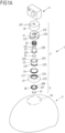
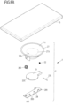
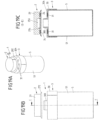
- FIG. 1A , 1B to 6A-6C show a first embodiment of a connecting device 1, which—in the illustrated embodiment—serves to attach an electronic device in the form of a camera 4 to a helmet 5 (e.g., a ski or bicycle helmet).
- the camera 4 can be detachably connected to an attachment surface 50 of the helmet 5 via the connecting device 1, so that, for example, video recordings can be made when the helmet 5 is in use.
- the connecting device 1 has a closure module 2 that can be attached to an attachment assembly 3 on the side of the helmet 5.
- the closure module 2 consists of a plurality of interacting parts and is fixed to the camera 4.
- the connection of the closure module 2 to the camera 4 can (likewise) be detachable in order to be able to use the connecting device 1, for example, on different electronic devices.
- the closure module 2 has a housing part 20 which is cylindrically shaped and is firmly connected via fastening points 201 to an adjusting element 23 which is received centrally in the housing part 20.
- the adjusting element 23 has a shaft 230 and a fastening point 231 arranged thereon, via which the adjusting element 23 is fixed to the housing part 20. At an end facing away from the bottom of the housing part 20, the adjusting element 23 has a head portion 232 that projects radially outward beyond the shaft 230.
- the housing part 20 and the adjustment element 23, which is connected to the housing part 20 in a rotationally fixed manner, are firmly connected to the camera 4.
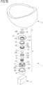
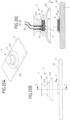
- the section view according to Fig. 2C can be removed, the adjusting element 23 lies in a cylindrical cavity 253 of a cylinder part 25 such that the head section 232 is slidably guided on an inner surface 250 of the cylinder part 25.
- the cylinder part 25, which is cylindrical with a circular cross-section, is firmly connected to a guide part 21 which has an opening 212 through which the adjusting element 23 engages with its shaft 230.
- a collar 213 projects axially from a base of the guide part 21 facing the base of the housing part 20, into which collar the cylinder part 25 engages and via which the cylinder part 25 is firmly connected to the guide part 21 (for example by welding or gluing).
- the guide part 21 also has a cylindrical basic shape, with a cylindrical outer surface 210 that extends circumferentially around the cylinder part 25 accommodated within the guide part 21 and is thus arranged radially outside the cylinder part 25.
- a plurality of circumferentially offset, parallel, helical guideways 211 are formed on the outer surface 210. These guideways are formed as slotted guides in the outer surface 210 and engage with guide elements 202 in the form of pins on the housing part 20 (projecting radially inward from a outer surface 200 of the housing part 20).
- the housing part 20 Due to the engagement of the guide elements 202 of the housing part 20 in the guide tracks 211 of the guide part 21, the housing part 20 (and above it also the adjusting element 23) is positively guided on the guide part 21 about a rotation axis R, so that when the housing part 20 is rotated about the rotation axis R, the structural unit formed from the housing part 20 and the adjusting element 23 follows the helical guide tracks 211 and the adjusting element 23 is thereby moved axially within the cylinder part 25.
- the cylinder part 25 is firmly connected to a vacuum element 27 in the form of an elastic cup element 27, in that the cylinder part 25 engages in a collar 270 of the vacuum element 27 and is clamped to the vacuum element 27 via a circumferential tension spring 26.
- the vacuum element 27 is thus firmly connected, in particular also fluid-tight, to the cylinder part 20.
- the adjusting element 23 is prestressed by a prestressing element in the form of a compression spring 22 surrounding the shaft 230 relative to the guide part 21 and thus relative to the cylinder part 25 in the direction of the Fig. 2C shown starting position.
- a prestressing element in the form of a compression spring 22 surrounding the shaft 230 relative to the guide part 21 and thus relative to the cylinder part 25 in the direction of the Fig. 2C shown starting position.
- the head portion 232 of the adjusting element 23 thus comes to rest at an end of the cylinder part 25 that faces away from the guide part 21.
- the guide part 21 is retracted to its maximum extent into the housing part 20.
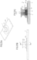
- the attachment surface 50 on the helmet 5 serves for attaching the vacuum element 27 in the form of a cup element.
- the attachment assembly 3 with an attachment part 30 and a magnetic element 31 received in a receiving opening 302 of the attachment part 30 is arranged on the attachment surface 50 of the helmet 5.
- the shutter module 2 for connecting the camera 4 to the helmet 5 is attached to this attachment assembly 3.
- the closure module 2 has a magnetic element 24, which is received in a receiving opening 234 of the adjustment element 23 and which, when the closure module 2 is attached to the attachment surface 50, interacts with the magnetic element 31 of the attachment assembly 3 in a magnetically attractive manner, so that the closure module 2 (with the camera 4 arranged thereon) is magnetically attracted to the attachment assembly 3 of the helmet 5.
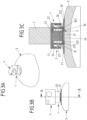
- a form-fitting section 233 in the form of a conical recess is formed, which, when the closure module 2 is attached, engages with an associated form-fitting section 300 in the form of a conical elevation on the attachment part 30, so that the closure module 2 is attached to the attachment assembly 3 of the helmet 5 in a defined manner.
- the positive locking between the positive locking sections 233, 300 serves to advantageously absorb transverse forces in the plane of the attachment surface 50 when the connecting device 1 is closed. Furthermore, the closure module 2 engages the attachment assembly 3 in a centered manner via the positive locking.
- the vacuum element 27 is elastically deformed at a cup-shaped edge section 272 projecting radially beyond the cylinder part 25, whereby air escapes from a space B formed between the vacuum element 27 and the attachment surface 50 and thus, when the closure module 2 is loaded, a suction vacuum acts between the vacuum element 27 and the attachment surface 50.
- pulse-like impact forces can be exerted on the connecting device 1 when using the Helmet 5 are absorbed and diverted so that the camera 4 is held securely and reliably on the helmet 5 even under impact loads.
- an engagement section 252 in the form of a toothing is formed, which, when the closure module 2 is attached to the attachment assembly 3, engages positively with a circumferential engagement section 301 in the form of a toothing on the attachment part 30, as can be seen from a synopsis of Fig. 2C and 3C and Fig. 1A and 1B can be seen.
- the cylinder part 25 and, above it, also the guide part 21 and the vacuum element 27 are fixed in a rotationally fixed manner to the attachment assembly 3 and thus to the helmet 5, so that torsional forces acting on the vacuum element 27 can also be effectively absorbed and dissipated.
- the camera 4 is thus rigidly attached to the helmet 5 via the connecting device 1.
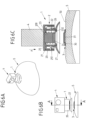
- the camera 4 and above it also the housing part 20 and the adjustment element 23 connected thereto are rotated in a direction of rotation D about the axis of rotation R relative to the cylinder part 25. Due to the engagement of the engagement sections 252, 301 on the side of the cylinder part 25 and the attachment part 30, it is ensured that the cylinder part 23 cannot rotate during this twisting movement and thus the adjustment element 23 is moved within the cylindrical cavity 253 of the cylinder part 25.
- the adjusting element 23 is adjusted axially along the rotation axis R within the cylinder part 25 and thus, as can be seen from Fig. 4C visible, from the attachment part 30.
- This causes, on the one hand, that the magnetic elements 24, 31 are moved away from each other, so that the magnetic attraction between the magnetic elements 24, 31 is weakened.
- this causes the head section 232 to slide within the cavity 253 and to sweep over a flow opening 251 in the wall of the cylinder part 25, so that an air flow F can flow into the space B through the flow opening 251 and a negative pressure in the space B is thus equalized.
- the helical guide of the housing part 20 on the guide part 21 allows for easy adjustment of the adjustment element 23. Releasing the connecting device 1 can thus be haptically pleasant and comfortable for a user, while the connecting device 1 is highly resilient in the connected position.
- the adjustment element 23 returns to its original position due to the preloading effect of the preloading element 22 in the form of a compression spring, rotating the cylinder part 25 and the adjustment element 23 relative to each other.
- the closure module 2 can thus be reattached to the attachment assembly 3 if desired.
- a negative pressure between the vacuum element 27 and the contact surface 50 is particularly effective in the case of sudden, short-term loads.
- a load e.g., tensile load
- a force acts in the direction of enlarging the space B, which leads to a negative pressure in this space B.
- the vacuum element 27, which forms a flat seal against the contact surface 50, can thus effectively absorb particularly sudden loads.
- the magnetic elements 24, 31, additionally support the attachment of the closure module 2 and the attachment assembly 3 to each other, pressing the vacuum element 27 against the attachment surface 50.
- the connecting device 1 can also ensure emergency tearing off in the case of larger, longer-lasting loads. For example, if a (predetermined) limit force, the camera 4 can be torn off the helmet 5, releasing the vacuum element 27 from the attachment surface 50.
- the vacuum element 27 and the vacuum force provided on the vacuum element 27 can be dimensioned accordingly.
- the connecting device 1 serves to attach a mobile phone 5 or another electronic device (for example, a navigation device), for example, in a vehicle, for example on the dashboard or on the windshield of the vehicle.
- the attachment assembly 3 is arranged according to the invention on a housing surface of the mobile phone 5 or the other electronic device serving as an attachment surface 50, while the closure module 2 can be arranged on the vehicle, for example by at least partially integrating the closure module 2 into a dashboard and thus recessing it.
- a closure module 2 is to be attached to an attachment component 50 in the form of an attachment surface on an electronic device 5 or another assembly.
- the closure module 2 has a vacuum element 27, which has a flexible edge portion 272 and is to be connected to the attachment component 50 in the form of the attachment surface on the assembly 5 by means of the flexible edge portion 272, subjected to elastic deformation to provide a vacuum effect.
- the flexible edge portion 272 extends circumferentially as a cup element around a body 273, on which a flow opening 274 is formed and on which an adjustment element 23 in the form of a flap element is articulated via bearing elements 275 and an axle element 276.
- An actuating element 28 is also arranged on the axle element 276, which interacts with the adjusting element 23 in the form of the flap element in order to actuate the adjusting element 23 to release the closure module 2 from the attachment component 50.
- actuating element 28 is guided by a spring element 280 in the form of a tension spring in the direction of Fig. 9A-9C shown
- the adjusting element 23 is spring-loaded into the initial position by a pre-tensioning element 22 in the form of a compression spring.
- Fastening points 283 in the form of, for example, screw holes are provided on the actuating element 28, via which the actuating element 28 can be connected to an associated, further assembly.
- the actuating element 28 can be secured to a vehicle, for example to a dashboard of a motor vehicle, in order to (removably) secure an assembly 5, for example, an electronic device in the form of a mobile phone or the like, to the vehicle.
- the adjustment element 23 is adjusted by actuating the actuating element 28, so that the flow opening 274 is released and an air flow can flow through the flow opening 274 between the vacuum element 27 and the attachment component 50, as shown in Fig. 10A-10C is shown.
- a negative pressure effect between the negative pressure element 27 and the attachment component 50 is thus eliminated, so that no holding forces act between the closure module 2 and the attachment component 50 (anymore).
- the actuating element 28 is tilted about the axis element 276 relative to the vacuum element 27, as can be seen from Fig. 10A-10C can be seen.
- the actuating element 28 acts on the adjusting element 23 with a section 281 remote from the head end 282 and also pivots the adjusting element 23 about the axis element 276.
- the adjusting element 23 is thus moved—indirectly via the actuating element 28—out of its closed position and releases the flow opening 274, so that the closure module 2 can be released from the attachment component 50.
- the spring element 280 is tensioned, as can be seen from Fig. 10A-10C can be seen.
- the pre-tensioning element 22 is tensioned under pressure.
- the actuating element 28 and the adjusting element 23 return to their respective starting positions due to the spring action, shown in Fig. 9A-9C , so that when the actuating element 28 is not actuated, the flow opening 274 is closed and the vacuum element 27 can thus be attached to an attachment component 50 to reconnect the closure module 2.
- Magnetic elements can be arranged on the one hand on the closure module 2 and on the other hand on the attachment component 50 in order to magnetically support the attachment of the closure module 2 to the attachment component 50.
- the connecting device 1 can also be non-magnetic and hold the closure module 2 to the attachment component 50 solely due to the negative pressure effect.
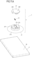
- an adjusting element 23 is slidably arranged on a vacuum element 27 of a closure module 2 of a connecting device 1.
- the vacuum element 27 in turn has a flexible, elastically deformable edge section 272 in the form of a cup element, with which the vacuum element 27 can be attached to a flat attachment component 50 of an assembly 5 in order to be in the attached position ( Fig. 12A-12C ) to hold the closure module 2 on the attachment component 50 due to a negative pressure effect.
- an adjusting element 23 is displaceably guided on a body 273 of the vacuum element 27 along a guide direction extending transversely to an attachment direction A, in that the adjusting element 23 engages with a guide piece 236 in an associated guide device 277 on the body 273 of the vacuum element 27.
- the adjusting element 23 closes a flow opening 274 in the body 273 with a closing element 235 in the form of a pin, so that a negative pressure effect between the negative pressure element 27 and the attachment component 50 for holding the closure module 2 on the attachment component 50 exists when the closure module 2 is attached to the attachment component 50.
- a negative pressure effect between the negative pressure element 27 and the attachment component 50 for holding the closure module 2 on the attachment component 50 exists when the closure module 2 is attached to the attachment component 50.
- the flow opening 274 is closed, an inflow of air between the vacuum element 27 and the attachment component 50 via the flow opening 274 is prevented.
- the adjustment element 23 can be moved transversely to the attachment direction A on the body 273 of the vacuum element 27, as shown in Fig. 13A-13C is shown.
- a prestressing element in the form of a compression spring acting between the adjusting element 23 and the vacuum element 27 is tensioned under pressure, and the flow opening 274 is released so that an air flow can flow between the vacuum element 27 and the attachment component 50 and a vacuum effect between the vacuum element 27 and the attachment component 50 is thus canceled.
- the adjusting element 23 After completion of the actuation, the adjusting element 23 is automatically returned to the starting position according to the pressure effect of the pre-tensioning element 22.
- Fig. 12A-12C reset, so that in the initial position when the adjusting element 23 is not actuated, the flow opening 274 is again closed and the closure module 2 can thus be attached again to an associated attachment component 50 of an assembly 5.
- the adjusting element 23 has fastening points 283 via which an associated assembly can be fastened to the adjusting element 23.
- the adjusting element 23 is thus actuated by a relative movement between the assembly connected to the adjusting element 23 and the assembly 5 to which the closure module 2 is attached. For example, a user can grip the assembly 5 in order to move the adjusting element 23 toward the vacuum element 27 and thus detach the assembly 5 from the closure module 2.
- the assembly 5 can, for example, be an electronic device in the form of a mobile phone or the like.
- the adjustment element 23, on the other hand, can be fixed to a vehicle, for example, to a dashboard of a motor vehicle, so that the assembly 5 can be releasably attached to the vehicle via the connecting device 1.
- the vacuum element is designed as an elastic cup element.
- this is not mandatory.
- rigid, non-elastic elements cooperate to create a negative pressure and thus to provide a holding force, although this is not within the scope of the present invention.
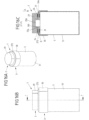
- the connecting device 1 has a closure module 2 that can be attached to an assembly 5.
- the closure module 2 of the connecting device 1 which is rigid and inelastic, can, for example, be precisely inserted into an attachment component 50 in the form of an opening 500 formed in the assembly 5, so that the cylinder part 23 is received in a substantially fluid-tight manner within the opening 500.
- a negative pressure is created between the cylinder part 25 and the walls of the opening 500, so that the closure module 2 is fixed to the assembly 5.
- An adjusting element 23 adjustable within the cylinder part 25 can be adjusted in a manner analogous to that described above in order to release the connecting device 1 by opening a flow path between a flow opening 251 in the cylinder part 25 and a space formed between the cylinder part 25 and the walls of the opening 500, so that air can flow into the space and the cylinder part 25 can thus be removed from the opening 500.
- the cylinder part 25 can be inserted precisely into the opening 500, thus creating a fluid-tight transition between the cylinder part 25 and the walls of the opening 500.
- the outer shape of the cylinder part 25 can be circular-cylindrical, although the cylinder part 25 can also have a different outer shape, for example, a polygonal outer shape or any other cross-sectional shape.
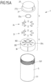
- Fig. 15A , 15B to 19A-19C show an embodiment of a container in the form of a drinking bottle, in which a container body 51 of an assembly 5 can be connected to a lid 29 in order to close the container body 51.
- the lid 29 is part of a closure module 2 of a connecting device 1, via which the lid 29 can be firmly but detachably connected to the container body 51.
- the connecting device 1 is formed by the closure module 2, of which the lid 29 is a component, and an attachment assembly 3 with an attachment part 30, which is to be connected to the container body 51 via a thread 501.
- the attachment part 30 has a form-fitting section 300 in the form of a protruding pin piece, which has a central opening through which a user can drink from the drinking bottle, for example, when the lid 29 is removed.
- the cover 29 of the closure module 2 forms, together with a flexible, circumferential edge section 272, a vacuum element 27 which can be attached to the attachment part 30 of the attachment assembly 3 in an attachment direction A and in the attached position ( Fig. 17A-17C ) is held on the attachment part 30 under the effect of negative pressure.
- an engagement opening 256 is formed, into which the form-fitting section 300 of the attachment part 30 engages when the closure module 2 is attached.
- a seal 254 in the form of an O-ring is arranged on the inner surface of the engagement opening 256, which seals off a transition between the lid 29 and the form-fitting section 300 in a fluid-tight, in particular moisture-tight, manner, so that liquid cannot penetrate out of the container 50 when the lid 29 is attached to the container body 51.
- the attachment part 30 On a surface 304 facing the cover 21, the attachment part 30 has receiving openings 302 into which magnetic elements 31 are inserted and connected to the attachment part 30. Likewise, receiving openings 255 are formed on the inside of the cover 29, into which magnetic elements 24 are inserted and thus held on the cover 29.
- the magnetic elements 31 on the attachment part 30, on the one hand, and the magnetic elements 24 on the cover 29, on the other hand, are evenly distributed and alternately polarized, viewed circumferentially around the attachment direction A.
- a magnetic element 31 of the attachment part 30 thus points with a north pole N toward the cover 29, while adjacent magnetic elements 31 each point with a south pole S toward the cover 29 and then again follow north poles N.
- a magnetic element 24 of the cover 29 points with a south pole S toward the attachment part 30, while adjacent magnetic elements 24 each point with a north pole N toward the attachment part 30 and then again follow south poles S.
- the lid 29 can be rotated along an opening direction O, along which the lid 29 can be rotated about a rotation axis R defined by the engagement of the form-fitting section 300 in the engagement opening 256 relative to the attachment part 30, whereby the magnetic elements 24, 31 with like-like poles are brought closer together and thus a magnetic repulsion is created between the magnetic elements 24, 31.
- This magnetic repulsion can weaken or even exceed the negative pressure effect between the lid 29 and the attachment part 30, so that the lid 29 can be easily released from the attachment part 30 in the opposite direction to the attachment direction A, and the drinking bottle can thus be opened.
- This is in the transition from Fig. 18A-18C towards Fig. 19A-19C
- This rotation can also open a flow opening.
- a connection of a lid 29 with a container 5 of the type described is not only conceivable and possible with a drinking bottle, for example for use on a bicycle, but can also be used with completely different, arbitrary containers that can be closed with a lid.
- FIG. 20A-20C and 21A-21C show an embodiment of a connecting device 1, which has a closure module 2 with a vacuum element 27, which can be attached in an attachment direction A to an attachment part 30 of an attachment assembly 3 connected to an assembly 5.
- a further assembly can be connected to the vacuum element 27, so that the assembly 5, for example an electronic device in the form of a mobile phone, can be arranged on the further assembly via the connecting device 1.
- the vacuum element 27 has a flexible edge portion 272 in the form of a cup element. Furthermore, a magnetic element 24 is arranged on a body 273, which magnetically interacts with a magnetic element 31 on the attachment part 30 of the attachment assembly 3 when the closure module 2 is attached to the attachment assembly 3, thus magnetically supporting the attachment of the closure module 2 to the attachment assembly 3.
- the closure module 2 is released from the attachment assembly 3 by pulling or tilting the vacuum element 27.
- electrical contact elements 6 are arranged on the closure module 2, which, when the closure module 2 is attached to the attachment assembly 3, make electrical contact with associated counter-contact elements 7 on the side of the attachment assembly 3, as can be seen from Fig. 20C in conjunction with Fig. 21C can be seen. Via the contact elements 6 and the counter-contact elements 7, an electrical connection can thus be established between the assembly 5 assigned to the attachment assembly 30 and an assembly assigned to the closure module 2, for example in order to provide an electrical supply or a data connection.
- the electrical contact elements 6 have contact pins 61, which are elastically supported on the body 273 of the vacuum element 27 via spring elements 62 and are connected to electrical lines 60.
- the counter-contact elements 7, on the other hand, can be designed, for example, as contact pads or the like on an upper side of the attachment part 30 facing the vacuum element 27, so that in a position where the closure module 2 ( Fig. 21A-21C ) the contact elements 6 make electrical contact with the mating contact elements 7.
- Fig. 22A-22C to 24A-24C The embodiment shown is identical to that shown in Fig. 1A , 1B to 6A-6C described embodiment, wherein additionally on the closure module 2 on the one hand and on the attachment assembly 3 on the other hand electrical contact elements 6 are arranged, which when the closure module ( Fig. 24A-24C ) can electrically contact one another and thus establish an electrical connection between the modules assigned to the connecting device 1, for example for an electrical supply of a module 5, for example an electronic device in the form of a mobile phone, or for providing a data connection.
Landscapes
- Engineering & Computer Science (AREA)
- General Engineering & Computer Science (AREA)
- Mechanical Engineering (AREA)
- Telephone Set Structure (AREA)
- Hooks, Suction Cups, And Attachment By Adhesive Means (AREA)
- Helmets And Other Head Coverings (AREA)
- Connection Of Plates (AREA)
- Fittings On The Vehicle Exterior For Carrying Loads, And Devices For Holding Or Mounting Articles (AREA)
Description
Die Erfindung betrifft ein elektronisches Gerät mit einer Verbindungsvorrichtung.The invention relates to an electronic device with a connecting device.
Eine Verbindungsvorrichtung weist ein Verschlussmodul auf, das an einer ersten der Baugruppen befestigbar ist und ein Unterdruckelement aufweist, das in eine Ansetzrichtung mit einer Ansetzkomponente der anderen, zweiten der Baugruppen zum Verbinden der Baugruppen verbindbar ist und in einer verbundenen Stellung derart mit der Ansetzkomponente wechselwirkt, dass bei Belastung des Verschlussmoduls und der Ansetzkomponente entgegen der Ansetzrichtung relativ zueinander das Unterdruckelement und die Ansetzkomponente aufgrund einer Unterdruckwirkung zwischen dem Unterdruckelement und der Ansetzkomponente aneinander gehalten sind.A connecting device has a closure module which can be fastened to a first of the assemblies and has a vacuum element which can be connected in an attachment direction to an attachment component of the other, second of the assemblies for connecting the assemblies and which interacts with the attachment component in a connected position such that when the closure module and the attachment component are loaded relative to one another counter to the attachment direction, the vacuum element and the attachment component are held together due to a vacuum effect between the vacuum element and the attachment component.
Eine Verbindungsvorrichtung soll vorliegend insbesondere zum Befestigen eines elektronischen Geräts an einer zugeordneten Baugruppe dienen können. So kann die Verbindungsvorrichtung beispielsweise die Befestigung einer Kamera an einem Helm (beispielsweise einem Skihelm oder einem Fahrradhelm) oder auch die Befestigung eines Mobiltelefons oder eines anderen elektronischen Geräts in einem Fahrzeug, z.B. an der Windschutzscheibe oder am Armaturenbrett eines Fahrzeugs, ermöglichen.In the present case, a connecting device is intended to be able to serve, in particular, for attaching an electronic device to an associated assembly. For example, the connecting device can enable the attachment of a camera to a helmet (e.g., a ski helmet or a bicycle helmet) or the attachment of a mobile phone or other electronic device in a vehicle, e.g., to the windshield or dashboard of a vehicle.
Wird eine Kamera an einem Helm, beispielsweise einem Skihelm oder einem Fahrradhelm, oder ein Mobiltelefon an einem Armaturenbrett eines Fahrzeugs oder am Lenker eines Fahrrads befestigt, so können bei Gebrauch impulsartige Stoßkräfte wirken, die aufgefangen und abgeleitet werden müssen und insbesondere nicht zu einem Lösen der Kamera oder des Mobiltelefons führen sollen. Eine Verbindungsvorrichtung zum Befestigen eines elektronischen Geräts, beispielsweise einer Kamera oder eines Mobiltelefons, soll daher insbesondere in der Lage sein, kurzzeitig wirkende, impulsartige Stoßkräfte aufzunehmen.If a camera is attached to a helmet, such as a ski helmet or a bicycle helmet, or a mobile phone is attached to a vehicle dashboard or the handlebars of a bicycle, impulsive impact forces may occur during use. These must be absorbed and dissipated and, in particular, should not cause the camera or mobile phone to become detached. A connecting device for attaching an electronic device, such as a camera or a mobile phone, should therefore be particularly capable of absorbing short-term, impulsive impact forces.
Zum Befestigen ganz unterschiedlicher Baugruppen aneinander, beispielsweise auch zum Befestigen eines elektronischen Geräts in Form eines Mobiltelefons oder Navigationsgeräts in einem Fahrzeug, sind Verbindungsvorrichtungen bekannt, die eine Halterung mittels Unterdruck bereitstellen. So ist aus der
Bei einer aus der
Eine aus der
Solche Verbindungsvorrichtungen sollen zum einen einfach schließbar sein, um eine Verbindung zwischen den zugeordneten Baugruppen herzustellen. Zudem ist aber auch wünschenswert, dass solche Verbindungsvorrichtungen auch einfach zu öffnen sind, um insbesondere ein ruckartiges Abreißen unter Überwindung eines Unterdrucks und gegebenenfalls zusätzlich einer magnetischen Verbindung zu vermeiden.Such connecting devices should, on the one hand, be easy to close in order to establish a connection between the associated assemblies. However, it is also desirable that such connecting devices be easy to open, in particular to prevent sudden tearing while overcoming a negative pressure and, if necessary, a magnetic connection.
Die
Aus der
Aufgabe der vorliegenden Erfindung ist es, eine Verbindungsvorrichtung zur Verfügung zu stellen, die einfach verwendbar, insbesondere einfach zu schließen, aber auch einfach wieder zu öffnen ist, bei vorteilhafter Verbindung der zugeordneten Baugruppen auch bei einer Stoßbelastung.The object of the present invention is to provide a connecting device which is easy to use, in particular easy to close, but also easy to open again, with an advantageous connection of the associated assemblies even under shock loads.
Diese Aufgabe wird durch einen Gegenstand mit den Merkmalen des Anspruchs 1 gelöst.This object is achieved by an article having the features of
Bevorzugte Merkmale sind im Anspruch 2 definiert.Preferred features are defined in
Ein elektronisches Gerät, insbesondere eine Kamera oder ein Mobiltelefon, weist eine Verbindungsvorrichtung zum lösbaren Verbinden des elektronischen Geräts mit einer weiteren Baugruppe auf. Die Verbindungsvorrichtung umfasst ein Verschlussmodul mit einem Unterdruckelement, das in eine Ansetzrichtung mit einer Ansetzkomponente zum Verbinden des elektronischen Geräts mit der weiteren Baugruppe verbindbar ist und in einer verbundenen Stellung derart mit der Ansetzkomponente wechselwirkt, dass bei Belastung des Verschlussmoduls und der Ansetzkomponente entgegen der Ansetzrichtung relativ zueinander das Unterdruckelement und die Ansetzkomponente aufgrund einer Unterdruckwirkung zwischen dem Unterdruckelement und der Ansetzkomponente aneinandergehalten sind. Dabei ist vorgesehen, dass das Verschlussmodul ein erstes Magnetelement zum magnetischen Unterstützen der Verbindung des elektronischen Geräts mit der weiteren Baugruppe aufweist.An electronic device, in particular a camera or a mobile phone, has a connecting device for detachably connecting the electronic device to another assembly. The connecting device comprises a closure module with a vacuum element, which can be connected in an attachment direction to an attachment component for connecting the electronic device to the other assembly and in a connected position interacts with the attachment component in such a way that when the closure module and the attachment component are loaded relative to one another in a direction opposite to the attachment direction, the vacuum element and the attachment component are held together due to a vacuum effect between the vacuum element and the attachment component. It is provided that the closure module has a first magnetic element for magnetically supporting the connection of the electronic device to the further assembly.
Das erste Magnetelement ist an dem Unterdruckelement oder an einem mit dem Unterdruckelement verbundenen Bauteil des Verschlussmoduls. Zusätzlich ist ein zweites Magnetelement an der Ansetzkomponente befestigt und derart mit dem ersten Magnetelement wechselwirken, dass ein Ansetzen des Verschlussmoduls an die Ansetzkomponente durch magnetische Anziehung unterstützt wird.The first magnetic element is attached to the vacuum element or to a component of the closure module connected to the vacuum element. Additionally, a second magnetic element is attached to the attachment component and interacts with the first magnetic element in such a way that magnetic attraction assists attachment of the closure module to the attachment component.
Das elektronische Gerät weist somit eine Verbindungsvorrichtung auf, die ein einfaches, jedoch belastbares Verbinden des elektronischen Geräts mit einer weiteren Baugruppe (zum Beispiel einem Helm, insbesondere einem Sporthelm wie zum Beispiel einem Skihelm, oder einem Fahrzeug, zum Beispiel einem Fahrrad oder einem Kraftfahrzeug, zum Beispiel einem Armaturenbrett in einem Fahrzeuginnenraum eines Kraftfahrzeugs) ermöglicht. Das Verbinden des elektronischen Geräts mit der weiteren Baugruppe erfolgt hierbei über die Verbindungsvorrichtung, deren Verschlussmodul zum einen durch Unterdruckwirkung und zum anderen durch magnetische Wechselwirkung mit der Ansetzkomponente wechselwirkt und somit in verbundener Stellung an der Ansetzkomponente gehalten ist.The electronic device thus has a connecting device that enables a simple yet resilient connection of the electronic device to another assembly (for example, a helmet, in particular a sports helmet such as a ski helmet, or a vehicle, for example, a bicycle or a motor vehicle, for example, a dashboard in the interior of a motor vehicle). The electronic device is connected to the other assembly via the connecting device, the locking module of which interacts with the attachment component on the one hand through negative pressure and on the other hand through magnetic interaction and is thus held in the connected position on the attachment component.
Aufgrund der Unterdruckwirkung können insbesondere Stoßbelastungen vorteilhaft aufgefangen und abgeleitet werden und führen nicht zu einem Lösen des elektronischen Geräts von der weiteren Baugruppe. Durch die magnetische Wechselwirkung kann die Verbindungsvorrichtung insbesondere einfach geschlossen werden, unter selbsttätiger Herstellung einer Unterdruckwirkung zwischen dem Unterdruckelement und der Ansetzkomponente.Due to the vacuum effect, shock loads, in particular, can be advantageously absorbed and dissipated, preventing the electronic device from becoming detached from the rest of the assembly. The magnetic interaction allows the connecting device to be easily closed, automatically creating a vacuum effect between the vacuum element and the attachment component.
Das Unterdruckelement weist ein zumindest abschnittsweise elastisch ausgebildetes Napfelement auf oder ist durch ein solches Napfelement gebildet. Das Unterdruckelement kann somit beim Ansetzen des Verschlussmoduls an die Ansetzkomponente elastisch verformt werden, was eine Unterdruckwirkung zwischen dem Unterdruckelement und der Ansetzkomponente für einen festen Halt begünstigt.The vacuum element has a cup element that is at least partially elastically designed or is formed by such a cup element. The vacuum element can thus be elastically deformed when the closure module is attached to the attachment component, which promotes a negative pressure effect between the vacuum element and the attachment component for a firm hold.
In einer Ausgestaltung weist das Verschlussmodul ein oder mehrere elektrische Kontaktelemente auf, die zum elektrischen Kontaktieren mit einem oder mehreren der Ansetzkomponente zugeordneten Gegenkontaktelementen dienen, wenn das Verschlussmodul bei geschlossener Verbindungsvorrichtung an die Ansetzkomponente angesetzt ist. Über die Verbindungsvorrichtung kann somit auch eine elektrische Verbindung hergestellt werden - über eine mechanische Verbindung zum Halten des elektronischen Geräts an einer zugeordneten Baugruppen hinaus. So können über ein oder mehrere elektrische Kontaktelemente beispielsweise Ströme für eine elektrische Versorgung zum Beispiel zum Aufladen des elektronischen Geräts übertragen werden, oder es kann eine Datenverbindung zum Austausch von Datensignalen bereitgestellt werden.In one embodiment, the closure module has one or more electrical contact elements that serve to make electrical contact with one or more mating contact elements assigned to the attachment component when the closure module is attached to the attachment component with the connecting device closed. An electrical connection can thus also be established via the connecting device—in addition to a mechanical connection for holding the electronic device to an associated assembly. For example, currents for an electrical supply, for example for charging the electronic device, can be transmitted via one or more electrical contact elements, or a data connection can be provided for exchanging data signals.
Das Verschlussmodul weist beispielsweise ein relativ zu dem Unterdruckelement verstellbares Verstellelement auf, das zum Lösen des Unterdruckelements von der Ansetzkomponente relativ zu dem Unterdruckelement bewegbar ist und mit dem die erste der Baugruppen derart verbindbar ist, dass eine Relativbewegung zwischen der ersten der Baugruppen und der zweiten der Baugruppen eine Bewegung des Verstellelements bewirkt.The closure module has, for example, an adjusting element which is adjustable relative to the vacuum element and which is movable relative to the vacuum element in order to release the vacuum element from the attachment component and to which the first of the assemblies is connectable in such a way that a relative movement between the first of the assemblies and the second of the assemblies causes a movement of the adjusting element.
Die Verbindungsvorrichtung umfasst somit ein Verstellelement, das an dem Verschlussmodul angeordnet ist und relativ zu dem Unterdruckelement verstellbar ist. Das Verstellelement ermöglicht ein Lösen des Unterdruckelements von der Ansetzkomponente, indem die dem Verschlussmodul zugeordnete erste Baugruppe derart mit dem Verstellelement wirkverbunden werden kann, dass eine Bewegung der ersten Baugruppe relativ zu der zweiten Baugruppe zu einem Bewegen des Verstellelements führt.The connecting device thus comprises an adjusting element arranged on the closure module and adjustable relative to the vacuum element. The adjusting element enables the vacuum element to be released from the attachment component by operatively connecting the first assembly associated with the closure module to the adjusting element in such a way that movement of the first assembly relative to the second assembly results in movement of the adjusting element.
Die erste Baugruppe kann beispielsweise durch ein elektronisches Gerät wie zum Beispiel einen Fotoapparat oder ein Mobiltelefon verwirklicht sein. Die erste Baugruppe kann hierbei unmittelbar oder mittelbar mit dem Verstellelement verbunden sein derart, dass ein Nutzer zum Lösen der Verbindungsvorrichtung an der ersten Baugruppe, zum Beispiel an dem Fotoapparat oder dem Mobiltelefon, angreifen kann, um auf diese Weise auch das Verstellelement zu bewegen und somit das Verschlussmodul von der zugeordneten Ansetzkomponente zu lösen.The first assembly can be implemented, for example, by an electronic device such as a camera or a mobile phone. The first assembly can be connected directly or indirectly to the adjustment element such that a user can engage the first assembly, for example, the camera or mobile phone, to release the connecting device, thereby also moving the adjustment element and thus releasing the closure module from the associated attachment component.
Bei der Verbindungsvorrichtung wird eine Verbindung zwischen den aneinander zu befestigenden Baugruppen dadurch hergestellt, dass das mit einer ersten der Baugruppen verbundene Verschlussmodul an eine Ansetzkomponente der anderen, zweiten der Baugruppen (oder umgekehrt die Ansetzkomponente an das Verschlussmodul) angesetzt wird. Beim Ansetzen entsteht ein abgedichteter Raum zwischen dem Unterdruckelement und der Ansetzkomponente, sodass die Baugruppen aufgrund einer Unterdruckwirkung aneinander gehalten sind. Solch eine Verbindung kann insbesondere belastbar auf Stoß sein, sodass über die Verbindungsvorrichtung Stoßkräfte aufgefangen und abgeleitet werden können.In the connecting device, a connection is established between the assemblies to be fastened together by attaching the closure module connected to a first of the assemblies to an attachment component of the other, second of the assemblies (or vice versa, the attachment component to the closure module). During attachment, a sealed space is created between the vacuum element and of the attachment component, so that the assemblies are held together by a vacuum effect. Such a connection can be particularly resilient to impact, so that impact forces can be absorbed and dissipated via the connecting device.
Mittels der Verbindungsvorrichtung können beispielsweise eine Kamera an einem Helm oder ein Mobiltelefon in einem Fahrzeug, zum Beispiel an einer Windschutzscheibe oder an einem Armaturenbrett, befestigt werden.By means of the connecting device, for example, a camera can be attached to a helmet or a mobile phone can be attached to a vehicle, for example to a windshield or dashboard.
In der verbundenen Stellung der Verbindungsvorrichtung können das Unterdruckelement und die Ansetzkomponente zum Beispiel flächig aneinander anliegen, sodass effektiv kein Raum zwischen dem Unterdruckelement und der Ansetzkomponente besteht. Bei einer Belastung der Baugruppen relativ zueinander kann jedoch eine Kraft auf das Verschlussmodul relativ zu der Ansetzkomponente wirken, die in Richtung einer Vergrößerung oder Schaffung eines zwischen dem Unterdruckelement und der Ansetzkomponente gebildeten Raums wirkt, was einen Unterdruck zwischen dem Unterdruckelement und der Ansetzkomponente bewirkt und somit Haltekräfte erzeugt, die das Unterdruckelement an der Ansetzkomponente halten und tendenziell größer werden, je stärker das Verschlussmodul gegenüber der Ansetzkomponente belastet wird. Das Verschlussmodul wird somit aufgrund Unterdruckwirkung an der Ansetzkomponente gehalten, wenn das Verschlussmodul an die Ansetzkomponente angesetzt ist.In the connected position of the connecting device, the vacuum element and the attachment component can, for example, lie flat against one another so that there is effectively no space between the vacuum element and the attachment component. However, when the assemblies are loaded relative to one another, a force can act on the closure module relative to the attachment component that acts to enlarge or create a space between the vacuum element and the attachment component, causing a vacuum between the vacuum element and the attachment component and thus generating holding forces that hold the vacuum element to the attachment component and tend to increase the more the closure module is loaded relative to the attachment component. The closure module is thus held to the attachment component due to the vacuum effect when the closure module is attached to the attachment component.
Das Verschlussmodul kann hierbei eine Strömungsöffnung aufweisen, die durch Bewegen des Verstellelements relativ zum Unterdruckelement für einen Zustrom von Luft in einen zwischen dem Unterdruckelement und der Ansetzkomponente vorhandenen Raum frei gegeben werden kann. Das Verstellelement kann beispielsweise in der verbundenen Stellung der Verbindungsvorrichtung eine erste Stellung relativ zu dem Unterdruckelement einnehmen, in der die Strömungsöffnung (betrachtet aus Richtung eines Raums zwischen dem Unterdruckelement und der Ansetzkomponente) verschlossen ist, sodass ein Zustrom von Luft in den Raum unterbunden ist. Aus dieser ersten Stellung kann das Verstellelement in eine zweite Stellung bewegt werden, um die Strömungsöffnung freizugeben und einen Zustrom von Luft in einen zwischen dem Unterdruckelement und der Ansetzkomponente gebildeten Raum zu ermöglichen. Eine Unterdruckwirkung zwischen dem Unterdruckelement und der Ansetzkomponente besteht somit, aufgrund des Zustroms durch die Strömungsöffnung, nicht mehr, sodass das Verschlussmodul ohne Unterdruckwirkung von der Ansetzkomponente abgenommen werden kann.The closure module can have a flow opening that can be opened by moving the adjusting element relative to the vacuum element to allow air to flow into a space between the vacuum element and the attachment component. For example, in the connected position of the connecting device, the adjusting element can assume a first position relative to the vacuum element in which the flow opening is closed (viewed from the direction of a space between the vacuum element and the attachment component), preventing air from flowing into the space. From this first position, the adjusting element can be moved into a second position to open the flow opening and allow air to flow into a space formed between the vacuum element and the attachment component. Due to the flow through the flow opening, there is no longer any vacuum between the vacuum element and the attachment component, so that the closure module can be removed from the attachment component without any vacuum.
In einer vorteilhaften Ausgestaltung ist das Verstellelement in Richtung seiner ersten Stellung federvorgespannt. Das Verstellelement nimmt somit selbsttätig, wenn es nicht anderweitig betätigt ist, seine erste Stellung ein und verschließt somit, insbesondere in der verbundenen Stellung der Verbindungsvorrichtung, die Strömungsöffnung, sodass eine Unterdruckwirkung zwischen dem Unterdruckelement und der Ansetzkomponente entstehen kann.In an advantageous embodiment, the adjusting element is spring-loaded toward its first position. The adjusting element thus automatically assumes its first position when not otherwise actuated and thus closes the flow opening, particularly in the connected position of the connecting device, so that a negative pressure effect can arise between the negative pressure element and the attachment component.
Das Verschlussmodul weist hierzu vorzugsweise ein elastisches Vorspannelement auf, das zum Vorspannen des Verstellelements in Richtung der ersten Stellung dient. Bei Verstellen wird das Verstellelement entgegen der vorspannenden Wirkung des Vorspannelements bewegt, sodass nach Beendigung der Betätigung das Verstellelement selbsttätig in seine erste Stellung zurückgestellt wird.For this purpose, the locking module preferably has an elastic preloading element that serves to preload the adjustment element toward the first position. During adjustment, the adjustment element is moved counter to the preloading effect of the preloading element, so that after the end of the actuation, the adjustment element is automatically returned to its first position.
Das Unterdruckelement ist durch ein zumindest abschnittsweise elastisches Napfelement und die Ansetzkomponente durch eine an der zweiten Baugruppe gebildete Ansetzfläche, mit der das Unterdruckelement zum Verbinden der Baugruppen zum Bereitstellen einer Unterdruckwirkung in Anlage bringbar ist, ausgebildet. Das Unterdruckelement verwirklicht somit ein Bauteil nach Art eines elastischen Saugnapfes, das an einer Fläche der zugeordneten, zweiten Baugruppe angeordnet werden kann, um unter elastischer Verformung ein Vakuum zwischen dem Unterdruckelement und der Fläche zu bilden und dadurch Haltekräfte zum Halten der Baugruppen aneinander bereitzustellen.The vacuum element is formed by a cup element that is elastic at least in sections, and the attachment component is formed by an attachment surface formed on the second assembly, with which the vacuum element can be brought into contact to connect the assemblies and provide a vacuum effect. The vacuum element thus implements a component in the manner of an elastic suction cup that can be arranged on a surface of the associated second assembly to form a vacuum between the vacuum element and the surface under elastic deformation, thereby providing holding forces for holding the assemblies together.
Das Verstellelement kann zum Beispiel zum Öffnen einer Strömungsöffnung in Form eines Ventils bewegt werden, um auf diese Weise eine Luftströmung in einen Raum zwischen dem Unterdruckelement und der Ansetzkomponente zu ermöglichen. Alternativ ist aber auch denkbar und möglich, dass durch Bewegen des Verstellelements das Unterdruckelement in Form des Napfelements von der Fläche abgehoben, beispielsweise in senkrechter Richtung zur Fläche abgezogen wird, wobei zum Beispiel kraftumlenkende Elemente eine Trennkraft zwischen dem Verschlussmodul und der Ansetzkomponente bewirken können.The adjusting element can, for example, be moved to open a flow opening in the form of a valve, thus enabling air flow into a space between the vacuum element and the attachment component. Alternatively, it is also conceivable and possible that, by moving the adjusting element, the vacuum element in the form of a cup element is lifted from the surface, for example, in a direction perpendicular to the surface. Force-deflecting elements, for example, can create a separating force between the closure module and the attachment component.
Das Verstellelement ist, in einer Ausgestaltung, an dem Unterdruckelement oder an einem mit dem Unterdruckelement fest verbundenen Element geführt. Die Bewegung des Verstellelements relativ zu dem Unterdruckelement kann hierbei entlang einer geradlinigen oder auch gekrümmten, zum Beispiel kreisbogenförmig gebogenen Führungsbahn erfolgen. Durch die geführte Bewegung kann zum Beispiel eine Strömungsöffnung freigegeben werden, um auf diese Weise einen Luftstrom zwischen das Unterdruckelement und die Ansetzkomponente zuzulassen und somit eine Unterdruckwirkung zwischen dem Unterdruckelement und der Ansetzkomponente zu eliminieren.In one embodiment, the adjustment element is guided on the vacuum element or on an element firmly connected to the vacuum element. The movement of the adjustment element relative to the vacuum element can take place along a straight or curved guideway, for example, a circular arc. The guided movement can, for example, open a flow opening to allow air flow between the vacuum element and the attachment component, thus eliminating a negative pressure effect between the vacuum element and the attachment component.
Grundsätzlich kann das Verstellelement gegenüber dem Unterdruckelement verdrehbar, verschiebbar und/oder verkippbar sein. Beispielsweise kann das Verstellelement als Klappenelemente oder als Hebelelement verschwenkbar an dem Unterdruckelement oder an einem mit dem Unterdruckelement verbundenen Bauteil gelagert sein und kann relativ zu dem Unterdruckelement verschwenkt werden, um eine Strömungsöffnung freizugeben und somit eine Unterdruckwirkung zwischen dem Unterdruckelement und der Ansetzkomponente zu eliminieren.In principle, the adjusting element can be rotatable, displaceable, and/or tiltable relative to the vacuum element. For example, the adjusting element can be pivotably mounted on the vacuum element or on a component connected to the vacuum element as a flap element or lever element, and can be pivoted relative to the vacuum element to expose a flow opening and thus eliminate a negative pressure effect between the vacuum element and the attachment component.
Die erste Baugruppe ist unmittelbar oder mittelbar mit dem Verstellelement verbunden, sodass eine Bewegung an der ersten Baugruppe auch zu einer Bewegung des Verstellelements insbesondere zum Lösen des Verschlussmoduls von der Ansetzkomponente führt. Ist die erste Baugruppe unmittelbar an dem Verstellelement angeordnet, so ist die erste Baugruppe fest mit dem Verstellelement verbunden, beispielsweise durch eine Schraubverbindung. Ist die erste Baugruppe mittelbar mit dem Verstellelement verbunden, so kann die erste Baugruppe beispielsweise an einem Betätigungselement angeordnet sein, das derart mit dem Verstellelement wirkverbunden ist, dass bei einer Betätigung des Betätigungselements auch das Verstellelement bewegt wird. Das Betätigungselement kann beispielsweise als Hebel ausgebildet sein, der bei einem Verschwenken auf das Verstellelement einwirkt und dieses bewegt, sodass beispielsweise eine Strömungsöffnung zum Aufheben einer Unterdruckwirkung zwischen dem Unterdruckelement und der Ansetzkomponente freigegeben wird.The first assembly is directly or indirectly connected to the adjusting element, such that a movement of the first assembly also leads to a movement of the adjusting element, in particular to the release of the closure module from the attachment component. If the first assembly is arranged directly on the adjusting element, the first assembly is firmly connected to the adjusting element, for example by a screw connection. If the first assembly is indirectly connected to the adjusting element, the first assembly can, for example, be arranged on an actuating element that is operatively connected to the adjusting element in such a way that when the actuating element is actuated, the adjusting element is also moved. The actuating element can, for example, be designed as a lever that acts on the adjusting element when pivoted and moves it, so that, for example, a flow opening is opened to cancel out a negative pressure effect between the negative pressure element and the attachment component.
In einer konkreten Ausgestaltung weist das Verschlussmodul ein Zylinderteil auf, das fest mit dem Unterdruckelement verbunden ist und das Verstellelement führt. Beispielsweise kann das Verstellelement mit einem Kopfabschnitt (mit einem kreisförmigen Querschnitt) in einem zylindrischen Hohlraum (mit einem kreisförmigen Querschnitt) des Zylinderteils einliegen und gleitend entlang einer den zylindrischen Hohlraum umgebenden Innenfläche des Zylinderteils verstellbar sein. Das Verstellelement wirkt somit nach Art eines Kolbens in dem zylindrischen Hohlraum des Zylinderteils, sodass durch Verstellen des Verstellelements in dem zylindrischen Hohlraum des Zylinderteils das Volumen des Raums zwischen dem Unterdruckelement und der Ansetzkomponente vergrößert werden kann. Bei Verstellen wird das Verstellelement somit innerhalb des Zylinderteils bewegt und gleitet dadurch innerhalb des Hohlraums des Zylinderteils.In a specific embodiment, the closure module has a cylinder part that is firmly connected to the vacuum element and guides the adjusting element. For example, the adjusting element can be located with a head section (with a circular cross-section) in a cylindrical cavity (with a circular cross-section) of the cylinder part and can be slidably adjusted along an inner surface of the cylinder part surrounding the cylindrical cavity. The adjusting element thus acts like a piston in the cylindrical cavity of the cylinder part, so that by adjusting the adjusting element in the cylindrical cavity of the cylinder part, the volume of the space between the vacuum element and the attachment component can be increased. During adjustment, the adjusting element is thus moved within the cylinder part and thereby slides within the cavity of the cylinder part.
In einer Ausgestaltung ist das Verstellelement an einer entlang einem Abschnitt einer Helix erstreckten Führungsbahn gegenüber dem Zylinderteil geführt. Die Führungsbahn kann beispielsweise an einem Führungsteil ausgebildet sein, das eine umfänglich um das Zylinderteil erstreckte Mantelfläche aufweist und somit radial außerhalb des Zylinderteils angeordnet ist. Die Führungsbahn kann nach Art einer Kulisse in die Mantelfläche eingeformt sein, wobei in der Führungsbahn beispielsweise ein Führungselement eines mit dem Verstellelement verbundenen Gehäuseteils geführt ist.In one embodiment, the adjusting element is guided along a guideway extending along a section of a helix relative to the cylinder part. The guideway can For example, it can be formed on a guide part that has a circumferential surface extending around the cylinder part and is thus arranged radially outside the cylinder part. The guide track can be formed into the surface in the manner of a slotted guide, with a guide element of a housing part connected to the adjusting element being guided in the guide track, for example.
Denkbar und möglich ist in diesem Zusammenhang, eine einzelne Führungsbahn vorzusehen, entlang derer das Verstellelement geführt ist. Denkbar und möglich ist aber auch, mehrere umfänglich zueinander versetzte Führungsbahnen bereitzustellen, in die jeweils ein Führungselement eines mit dem Verstellelement verbundenen Gehäuseteils eingreift, sodass eine leichtgängige, definierte Führung des Verstellelements relativ zu dem Zylinderteil bereitgestellt wird, bei der ein Verkanten zwischen dem Verstellelement und dem Zylinderteil ausgeschlossen ist.In this context, it is conceivable and possible to provide a single guideway along which the adjustment element is guided. However, it is also conceivable and possible to provide several circumferentially offset guideways, each of which engages a guide element of a housing part connected to the adjustment element, thus providing smooth, defined guidance of the adjustment element relative to the cylinder part, preventing any jamming between the adjustment element and the cylinder part.
Die Führungsbahn erstreckt sich entlang eines Abschnitts einer Helix. Durch die Führung über die Führungsbahn kann das Verstellelement bei Verstellen somit graduell axial bewegt werden, entlang einer durch die Helix bereitgestellten Schraubenlinie. Eine Verdrehbewegung des Verstellelements wird somit in eine axiale Bewegung entlang der Zylinderachse des Zylinderteils übersetzt, sodass das Verstellelement leichtgängig durch schraubendes Verdrehen verstellbar sein kann.The guideway extends along a section of a helix. The guideway allows the adjustment element to be gradually moved axially during adjustment, along a helical line provided by the helix. A twisting movement of the adjustment element is thus translated into an axial movement along the cylinder axis of the cylinder part, allowing the adjustment element to be smoothly adjusted by screwing.
Über den in dem Hohlraum des Zylinderteils einliegenden Kopfabschnitt kann das Verstellelement vorzugsweise fluiddicht gegenüber der Innenfläche des Zylinderteils abgedichtet sein. Der Kopfabschnitt liegt hierzu z.B. so passgenau in dem Hohlraum des Zylinderteils ein, dass Luft nicht an dem Kopfabschnitt vorbeiströmen kann. An dem Kopfabschnitt vorbei kann somit keine Luft in den zwischen dem Unterdruckelement und der Ansetzkomponente gebildeten Raum einströmen, sodass - ohne Verstellen des Verstellelements - der Unterdruck in dem Raum für ein zuverlässiges Halten der Baugruppen aneinander aufrechterhalten wird.The adjustment element can preferably be sealed fluid-tight against the inner surface of the cylinder part via the head section located in the cavity of the cylinder part. For this purpose, the head section fits so precisely in the cavity of the cylinder part that air cannot flow past the head section. Thus, no air can flow past the head section into the space formed between the vacuum element and the attachment component, so that—without adjusting the adjustment element—the negative pressure in the space is maintained to reliably hold the assemblies together.
Der Kopfabschnitt kann passgenau in dem Hohlraum des Zylinderteils einliegen. Denkbar und möglich ist aber auch, zum Beispiel an dem Kopfabschnitt eine umlaufende Dichtung zum Abdichten des Übergangs zwischen dem Kopfabschnitt und der Innenfläche des Zylinderteils vorzusehen.The head section can fit snugly into the cavity of the cylinder part. However, it is also conceivable and possible to provide a circumferential seal on the head section, for example, to seal the transition between the head section and the inner surface of the cylinder part.
In einer Ausgestaltung ist die Strömungsöffnung an dem Zylinderteil gebildet. Die Strömungsöffnung wird bei Verstellen des Verstellelements aus der ersten Stellung heraus freigegeben, sodass ein Luftstrom zwischen das Unterdruckelement und die Ansetzkomponente strömen kann und eine Unterdruckwirkung zwischen dem Unterdruckelement und der Ansetzkomponente somit aufgehoben wird. Die Strömungsöffnung erfüllt die Funktion eines Ventils, das bei an die Ansetzkomponente angesetztem Unterdruckelement geschlossen ist, sodass eine Unterdruckwirkung zwischen dem Unterdruckelement und der Ansetzkomponente besteht. Zum Öffnen der Verbindungsvorrichtung kann die Strömungsöffnung durch Verstellen des Verstellelements geöffnet werden, sodass eine Luftströmung von außen zwischen das Unterdruckelement und die Ansetzkomponente strömen kann. Dadurch werden die Haltekräfte der Verbindungsvorrichtung aufgehoben, sodass die über die Verbindungsvorrichtung miteinander verbundenen Baugruppen in einfacher Weise voneinander gelöst werden können.In one embodiment, the flow opening is formed on the cylinder part. The flow opening is opened when the adjusting element is adjusted from the first position released so that an air flow can flow between the vacuum element and the attachment component, thus canceling out any negative pressure effect between the vacuum element and the attachment component. The flow opening acts as a valve which is closed when the vacuum element is attached to the attachment component, creating a negative pressure effect between the vacuum element and the attachment component. To open the connecting device, the flow opening can be opened by adjusting the adjusting element, allowing an air flow from the outside to flow between the vacuum element and the attachment component. This cancels out the holding forces of the connecting device, so that the assemblies connected to one another via the connecting device can be easily separated from one another.
Die Strömungsöffnung kann an der Zylinderwandung des Zylinderteils an einer axial zurückgesetzten Position gebildet sein, also an einer Position, die derart angeordnet ist, dass bei an die Ansetzkomponente angesetztem Unterdruckelement der Kopfabschnitt des Verstellelements zwischen der Strömungsöffnung und der Ansetzkomponente zu liegen kommt und somit einen Strömungsweg zwischen der Strömungsöffnung und einem Raum zwischen der Ansetzkomponente und dem Unterdruckelement schließt. Bei Verstellen gleitet das Verstellelement innerhalb des Hohlraums des Zylinderteils und überstreicht die Strömungsöffnung, sodass ein Strömungsweg zwischen das Unterdruckelement und die Ansetzkomponente freigegeben wird und somit Luft einströmen kann.The flow opening can be formed on the cylinder wall of the cylinder part at an axially recessed position, i.e., at a position arranged such that, when the vacuum element is attached to the attachment component, the head portion of the adjusting element lies between the flow opening and the attachment component, thus closing a flow path between the flow opening and a space between the attachment component and the vacuum element. During adjustment, the adjusting element slides within the cavity of the cylinder part and sweeps over the flow opening, opening a flow path between the vacuum element and the attachment component, allowing air to flow in.
Das Verschlussmodul weist, in einer Ausgestaltung, ein elastisches Vorspannelement auf, das zum Vorspannen des Verstellelements in Richtung der ersten Stellung dient. Das Verstellelement wird somit federelastisch in der ersten Stellung gehalten, beispielsweise mittels einer Druckfeder, die zwischen dem Verstellelement und dem Zylinderteil wirkt. Bei Verstellen wird das Verstellelement entgegen der vorspannenden Wirkung des Vorspannelements bewegt, sodass nach Beendigung der Betätigung das Verstellelement selbsttätig in seine erste Stellung zurückgestellt wird.In one embodiment, the locking module has an elastic preloading element that serves to preload the adjusting element toward the first position. The adjusting element is thus held in the first position by a spring, for example, by a compression spring acting between the adjusting element and the cylinder part. During adjustment, the adjusting element is moved against the preloading effect of the preloading element, so that after the actuation is completed, the adjusting element is automatically returned to its first position.
In einer Ausgestaltung kann an der Ansetzkomponente der zweiten Baugruppe, beispielsweise in Form einer planen Ansetzfläche, eine Ansetzbaugruppe zu befestigen sein, die ein Ansetzteil aufweist, mit dem das Verschlussmodul zum Verbinden der Baugruppen in Wechselwirkung gebracht werden kann. Die Ansetzbaugruppe kann den Halt der Verbindungsvorrichtung verbessern und insbesondere eine definierte Lage zwischen dem Verschlussmodul und der Ansetzkomponente bewirken, insbesondere auch zur Abstützung von zwischen dem Verschlussmodul und der Ansetzkomponente wirkenden Querkräften.In one embodiment, an attachment assembly can be attached to the attachment component of the second assembly, for example in the form of a flat attachment surface. The attachment assembly has an attachment part with which the closure module can interact to connect the assemblies. The attachment assembly can improve the hold of the connecting device and, in particular, ensure a defined position between the closure module and the attachment component, in particular also to support transverse forces acting between the closure module and the attachment component.
Beispielsweise kann das Verstellelement einen ersten Formschlussabschnitt und das Ansetzteil einen zweiten Formschlussabschnitt aufweisen. Bei Ansetzen des Verschlussmoduls und des Ansetzteils aneinander gelangen die Formschlussabschnitte formschlüssig miteinander in Eingriff derart, dass eine Querbewegung zwischen dem Verschlussmodul und der Ansetzkomponente gesperrt ist. Mittels der Formschlussabschnitte kann somit insbesondere eine Bewegung quer zu einer Ansetzrichtung, entlang derer das Verschlussmodul und die Ansetzkomponente aneinander ansetzbar sind, gesperrt werden, sodass in Querrichtung wirkende Kräfte (also in der Ebene der Ansetzfläche wirkende Kräfte) aufgenommen und abgestützt werden können.For example, the adjustment element can have a first form-fitting section, and the attachment part can have a second form-fitting section. When the closure module and the attachment part are attached to one another, the form-fitting sections engage one another in a form-fitting manner, preventing transverse movement between the closure module and the attachment component. Thus, the form-fitting sections can be used to prevent, in particular, movement transverse to an attachment direction along which the closure module and the attachment component are attached to one another, so that forces acting in the transverse direction (i.e., forces acting in the plane of the attachment surface) can be absorbed and supported.
Zusätzlich oder alternativ kann über diese Ansetzbaugruppe das Verschlussmodul auch in seiner Drehstellung gesichert sein, sodass auch Torsionskräfte aufgenommen und abgestützt werden können. Hierzu kann das Unterdruckelement oder ein mit dem Unterdruckelement verbundenes Element, zum Beispiel das Zylinderteil, einen ersten Eingriffsabschnitt aufweisen, während das Ansetzteil (an der anderen, zweiten Baugruppe) einen zweiten Eingriffsabschnitt aufweist. Bei Ansetzen des Verschlussmoduls und des Ansetzteils aneinander gelangen die Eingriffsabschnitte sperrend miteinander in Eingriff und sperren auf diese Weise eine Verdrehbewegung des Unterdruckelements gegenüber dem Ansetzteil.Additionally or alternatively, the locking module can also be secured in its rotational position via this attachment assembly, so that torsional forces can also be absorbed and supported. For this purpose, the vacuum element or an element connected to the vacuum element, for example, the cylinder part, can have a first engagement section, while the attachment part (on the other, second assembly) has a second engagement section. When the locking module and the attachment part are attached to one another, the engagement sections engage with one another in a locking manner, thus preventing any rotational movement of the vacuum element relative to the attachment part.
Die Eingriffsabschnitte können beispielsweise durch eine (vorzugsweise an einem kreisförmigen Randabschnitt umlaufende) Verzahnung an dem Unterdruckelement oder dem mit dem Unterdruckelement verbundenen Element einerseits und dem Ansetzteil andererseits gebildet sein.The engagement sections can be formed, for example, by a toothing (preferably running around a circular edge section) on the vacuum element or the element connected to the vacuum element on the one hand and the attachment part on the other hand.
In einer Ausführungsform weist das Verschlussmodul ein erstes Magnetelement zum magnetischen Unterstützen des Herstellens der Verbindung der Baugruppen miteinander auf. Dieses erste Magnetelement kann beispielsweise an dem Verstellelement angeordnet sein und wird somit mit dem Verstellelement zusammen bewegt. Alternativ oder zusätzlich kann ein Magnetelement auch an dem Unterdruckelement oder einem mit dem Unterdruckelement verbundenen Element, beispielsweise dem Zylinderteil, vorgesehen sein.In one embodiment, the closure module has a first magnetic element for magnetically supporting the connection of the assemblies to one another. This first magnetic element can, for example, be arranged on the adjustment element and is thus moved together with the adjustment element. Alternatively or additionally, a magnetic element can also be provided on the vacuum element or an element connected to the vacuum element, for example, the cylinder part.
Ein zweites Magnetelement kann demgegenüber an der Ansetzkomponente befestigt werden. Ein solches zweites Magnetelement kann beispielsweise an dem Ansetzteil angeordnet sein und zusammen mit dem Ansetzteil an der Ansetzkomponente angeordnet werden. Die Magnetelemente des Verschlussmoduls einerseits und der Ansetzkomponente andererseits dienen dazu, beim Ansetzen des Verschlussmoduls und der Ansetzkomponente aneinander eine magnetische Anziehungskraft bereitzustellen, sodass die Herstellung des Unterdrucks in magnetisch unterstützter Weise (vorzugsweise selbsttätig) erfolgt. Bei Ansetzen werden das Verschlussmodul und die Ansetzkomponente aufgrund der magnetischen Wechselwirkung magnetisch anziehend zueinander hingezogen, sodass ein (Beinahe-)Vakuum zwischen dem Unterdruckelement und der Ansetzkomponente bewirkt wird, beispielsweise indem das als elastisches Napfelement ausgebildete Unterdruckelement gegen die als Ansetzfläche ausgebildete Ansetzkomponente gepresst wird.A second magnetic element, in contrast, can be attached to the attachment component. Such a second magnetic element can, for example, be arranged on the attachment part and, together with the attachment part, on the attachment component. The magnetic elements of the closure module, on the one hand, and the attachment component, on the other hand, serve to hold the closure module and the attachment component together when attaching them. to provide a magnetic attraction force so that the negative pressure is created in a magnetically assisted manner (preferably automatically). Upon attachment, the closure module and the attachment component are magnetically attracted to each other due to the magnetic interaction, so that a (near) vacuum is created between the negative pressure element and the attachment component, for example, by pressing the negative pressure element, designed as an elastic cup element, against the attachment component, designed as an attachment surface.
Ist das erste Magnetelement an dem Verstellelement angeordnet, so wird das erste Magnetelement bei Verstellen des Verstellelements zusammen mit dem Verstellelement bewegt und kann dadurch von dem zweiten Magnetelement auf Seiten der Ansetzkomponente entfernt werden, sodass sich die magnetischen Anziehungskräfte abschwächen. Durch Verstellen des Verstellelements werden somit auch die magnetischen Haltekräften zumindest abgeschwächt, was zu einem einfachen, leichtgängigen, haptisch angenehmen Öffnen beitragen kann.If the first magnetic element is arranged on the adjustment element, the first magnetic element moves along with the adjustment element when the adjustment element is adjusted and can thus be removed from the second magnetic element on the attachment component side, so that the magnetic attraction forces are weakened. Adjusting the adjustment element also at least weakens the magnetic holding forces, which can contribute to a simple, smooth, and tactilely pleasant opening.
Das erste Magnetelement und das zweite Magnetelement können jeweils durch einen Permanentmagneten oder auch eine Anordnung von mehreren Permanentmagneten gebildet sein und wirken zum Schließen der Verbindungsvorrichtung magnetisch anziehend zusammen, indem sie mit ungleichnamigen Magnetpolen aufeinander zu weisen. Denkbar ist aber auch, dass ein Magnetelement durch einen Permanentmagneten oder eine Anordnung von mehreren Permanentmagneten gebildet ist, während das andere Magnetelement durch einen magnetischen Anker aus einem ferromagnetischen Material gebildet ist.The first magnetic element and the second magnetic element can each be formed by a permanent magnet or an arrangement of several permanent magnets and, to close the connecting device, interact in a magnetically attractive manner by facing each other with opposite magnetic poles. However, it is also conceivable for one magnetic element to be formed by a permanent magnet or an arrangement of several permanent magnets, while the other magnetic element is formed by a magnetic armature made of a ferromagnetic material.
In einer Ausgestaltung weist das Verschlussmodul ein oder mehrere elektrische Kontaktelemente auf, die zum elektrischen Kontaktieren mit einem oder mehreren der Ansetzkomponente zugeordneten Gegenkontaktelementen dienen, wenn das Verschlussmodul bei geschlossener Verbindungsvorrichtung an die Ansetzkomponente angesetzt ist. Über die Verbindungsvorrichtung kann somit auch eine elektrische Verbindung hergestellt werden - über eine mechanische Verbindung zum Halten von Baugruppen aneinander hinaus -, was insbesondere dann vorteilhaft sein kann, wenn über die Verbindungsvorrichtung zum Beispiel ein elektronisches Gerät an einer zugeordneten Baugruppe befestigt werden soll. In diesem Fall können über ein oder mehrere elektrische Kontaktelemente beispielsweise Ströme für eine elektrische Versorgung zum Beispiel zum Aufladen des elektronischen Geräts übertragen werden, oder es kann eine Datenverbindung zum Austausch von Datensignalen bereitgestellt werden.In one embodiment, the closure module has one or more electrical contact elements that serve to make electrical contact with one or more mating contact elements assigned to the attachment component when the closure module is attached to the attachment component with the connecting device closed. An electrical connection can thus also be established via the connecting device - in addition to a mechanical connection for holding assemblies together - which can be particularly advantageous if, for example, an electronic device is to be attached to an associated assembly via the connecting device. In this case, currents for an electrical supply, for example for charging the electronic device, can be transmitted via one or more electrical contact elements, or a data connection for exchanging data signals can be provided.
ist 12 Die Verbindungsvorrichtung dazu ausgebildet, ein elektronisches Gerät an einer zugeordneten Baugruppe zu befestigen. Beispielsweise kann die Verbindungsvorrichtung dazu dienen, eine Kamera an einem Helm, zum Beispiel einem Skihelm oder einem Fahrradhelm, zu befestigen. In anderer Ausgestaltung kann die Verbindungsvorrichtung auch dazu dienen, ein Mobiltelefon oder eine Navigationsgerät oder ein anderes elektronisches Kommunikations- oder Informationsgerät in einem Fahrzeug zu befestigen, beispielsweise an einer Windschutzscheibe oder an einem Armaturenbrett.12 The connecting device is designed to attach an electronic device to an associated assembly. For example, the connecting device can be used to attach a camera to a helmet, for example, a ski helmet or a bicycle helmet. In another embodiment, the connecting device can also be used to attach a mobile phone or a navigation device or another electronic communication or information device in a vehicle, for example, to a windshield or a dashboard.
Der der Erfindung zugrunde liegende Gedanke soll nachfolgend anhand der in den Figuren dargestellten Ausführungsbeispiele näher erläutert werden. Es zeigen:
- Fig. 1A
- eine Explosionsansicht eines Ausführungsbeispiels einer Verbindungsvorrichtung zum Verbinden einer Kamera mit einem Helm;
- Fig. 1B
- die Explosionsansichten gemäß
Fig. 1A , aus anderer Perspektive; - Fig. 2A
- eine Ansicht der Verbindungsvorrichtung, bei Ansetzen eines Verschlussmoduls an eine Ansetzkomponente in Form einer Ansetzfläche auf Seiten des Helms;
- Fig. 2B
- eine Seitenansicht der Anordnung;
- Fig. 2C
- eine Schnittansicht entlang der Linie A-A gemäß
Fig. 2B ; - Fig. 3A
- eine Ansicht der Verbindungsvorrichtung, bei an die Ansetzkomponente angesetztem Verschlussmodul;
- Fig. 3B
- eine Seitenansicht der Anordnung;
- Fig. 3C
- eine Schnittansicht entlang der Linie A-A gemäß
Fig. 3B ; - Fig. 4A
- eine Ansicht der Verbindungsvorrichtung beim Öffnen;
- Fig. 4B
- eine Seitenansicht der Anordnung;
- Fig. 4C
- eine Schnittansicht entlang der Linie A-A gemäß
Fig. 4B ; - Fig. 5A
- eine Ansicht der Verbindungsvorrichtung beim weiteren Öffnen;
- Fig. 5B
- eine Seitenansicht der Anordnung;
- Fig. 5C
- eine Schnittansicht entlang der Linie A-A gemäß
Fig. 5B ; - Fig. 6A
- eine Ansicht der Anordnung bei geöffneter Verbindungsvorrichtung;
- Fig. 6B
- eine Seitenansicht der Anordnung;
- Fig. 6C
- eine Schnittansicht entlang der Linie A-A gemäß
Fig. 6B ; - Fig. 7A
- eine Ansicht der Verbindungsvorrichtung, bei Verwendung zum Befestigen eines Mobiltelefons;
- Fig. 7B
- eine Seitenansicht der Anordnung gemäß
Fig. 7A ; - Fig. 7C
- eine Schnittansicht entlang der Linie B-B gemäß
Fig. 7B ; - Fig. 8A
- eine Explosionsansicht eines nicht anspruchsgemäßen Ausführungsbeispiels einer Verbindungsvorrichtung zum Verbinden zweier Baugruppen miteinander, zum Beispiel eines elektronischen Geräts in Form eines Mobiltelefon an einer anderen Baugruppe, zum Beispiel an einem Armaturenbrett eines Fahrzeugs;
- Fig. 8B
- eine andere Explosionsansicht der Verbindungsvorrichtung;
- Fig. 9A
- eine Ansicht der Verbindungsvorrichtung, bei an eine Ansetzkomponente angesetztem Verschlussmodul;
- Fig. 9B
- eine Seitenansicht der Anordnung gemäß
Fig. 9A ; - Fig. 9C
- eine Schnittansicht entlang der Linie A-A gemäß
Fig. 9B ; - Fig. 10A
- eine Ansicht der Verbindungsvorrichtung beim Öffnen zum Lösen des Verschlussmoduls von der Ansetzkomponente;
- Fig. 10B
- eine Seitenansicht der Anordnung gemäß
Fig. 10A ; - Fig. 10C
- eine Schnittansicht entlang der Linie C-C gemäß
Fig. 10B ; - Fig. 11A
- eine Explosionsansicht eines nicht anspruchsgemäßen Ausführungsbeispiels einer Verbindungsvorrichtung;
- Fig. 11B
- eine andere Explosionsansicht der Verbindungsvorrichtung;
- Fig. 12A
- eine Ansicht der Verschlussvorrichtung, bei an eine Ansetzkomponente angesetztem Verschlussmodul;
- Fig. 12B
- eine Seitenansicht der Anordnung gemäß
Fig. 12A ; - Fig. 12C
- eine Schnittansicht entlang der Linie A-A gemäß
Fig. 12B ; - Fig. 13A
- eine Ansicht der Verbindungsvorrichtung beim Öffnen zum Lösen des Verschlussmoduls von der Ansetzkomponente;
- Fig. 13B
- eine Seitenansicht der Anordnung gemäß
Fig. 13A ; - Fig. 13C
- eine Schnittansicht entlang der Linie B-B gemäß
Fig. 13B ; - Fig. 14
- eine schematische Ansicht einer nicht anspruchsgemäßen Ausführungsform einer Verbindungsvorrichtung;
- Fig. 15A
- eine Explosionsansicht einer nicht anspruchsgemäßen Ausführungsform einer Verbindungsvorrichtung an einem Behälterkörper zum Verbinden eines Deckels mit dem Behälterkörper;
- Fig. 15B
- eine andere Explosionsansicht der Anordnung gemäß
Fig. 15A ; - Fig. 16A
- eine Ansicht des Behälterkörpers beim Ansetzen des Deckels;
- Fig. 16B
- eine Seitenansicht der Anordnung gemäß
Fig. 16A ; - Fig. 16C
- eine Schnittansicht entlang der Linie F-F gemäß
Fig. 16B ; - Fig. 17A
- eine Ansicht des Behälterkörpers mit daran angesetztem Deckel;
- Fig. 17B
- eine Seitenansicht der Anordnung gemäß
Fig. 17A ; - Fig. 17C
- eine Schnittansicht entlang der Linie C-C gemäß
Fig. 17B ; - Fig. 18A
- eine Ansicht des Behälterkörpers mit dem daran angeordneten Deckel, beim Öffnen;
- Fig. 18B
- eine Seitenansicht der Anordnung gemäß
Fig. 18A ; - Fig. 18C
- eine Schnittansicht entlang der Linie G-G gemäß
Fig. 18B ; - Fig. 19A
- eine Ansicht des Behälterkörpers bei abgenommenem Deckel;
- Fig. 19B
- eine Seitenansicht der Anordnung gemäß
Fig. 19A ; - Fig. 19C
- eine Schnittansicht entlang der Linie E-E gemäß
Fig. 19B ; - Fig. 20A
- eine Ansicht eines weiteren Ausführungsbeispiels einer Verbindungsvorrichtung, vor Ansetzen eines Verschlussmoduls an eine Ansetzkomponente;
- Fig. 20B
- eine Seitenansicht der Anordnung gemäß
Fig. 20A ; - Fig. 20C
- eine Schnittansicht entlang der Linie B-B gemäß
Fig. 20B ; - Fig. 21A
- eine Ansicht der Verbindungsvorrichtung bei an die Ansetzkomponente angesetztem Verschlussmodul;
- Fig. 21B
- eine Seitenansicht der Anordnung gemäß
Fig. 21A ; - Fig. 21C
- eine Schnittansicht entlang der Linie A-A gemäß
Fig. 21B ; - Fig. 22A
- eine Ansicht des Ausführungsbeispiels gemäß
Fig. 1A ,1B bis 6A-6C , jedoch mit elektrischen Kontaktelementen an dem Verschlussmodul und der Ansetzbaugruppe, bei von der Ansetzbaugruppe gelöstem Verschlussmodul; - Fig. 22B
- eine Seitenansicht der Anordnung gemäß
Fig. 22A ; - Fig. 22C
- eine Schnittansicht entlang der Linie A-A gemäß
Fig. 22B ; - Fig. 23A
- die Verbindungsvorrichtung beim Ansetzen des Verschlussmoduls an die Ansetzbaugruppe;
- Fig. 23B
- eine Seitenansicht der Anordnung gemäß
Fig. 23A ; - Fig. 23C
- eine Schnittansicht entlang der Linie B-B gemäß
Fig. 23B ; - Fig. 24A
- eine Ansicht der Verbindungsvorrichtung, bei an die Ansetzbaugruppe angesetztem Verschlussmodul;
- Fig. 24B
- eine Seitenansicht der Anordnung gemäß
Fig. 24A ; und - Fig. 24C
- eine Schnittansicht entlang der Linie E-E gemäß
Fig. 24B .
- Fig. 1A
- an exploded view of an embodiment of a connecting device for connecting a camera to a helmet;
- Fig. 1B
- the exploded views according to
Fig. 1A , from a different perspective; - Fig. 2A
- a view of the connecting device when attaching a closure module to an attachment component in the form of an attachment surface on the side of the helmet;
- Fig. 2B
- a side view of the arrangement;
- Fig. 2C
- a sectional view along the line AA according to
Fig. 2B ; - Fig. 3A
- a view of the connecting device with the closure module attached to the attachment component;
- Fig. 3B
- a side view of the arrangement;
- Fig. 3C
- a sectional view along the line AA according to
Fig. 3B ; - Fig. 4A
- a view of the connecting device when opened;
- Fig. 4B
- a side view of the arrangement;
- Fig. 4C
- a sectional view along the line AA according to
Fig. 4B ; - Fig. 5A
- a view of the connecting device when further opened;
- Fig. 5B
- a side view of the arrangement;
- Fig. 5C
- a sectional view along the line AA according to
Fig. 5B ; - Fig. 6A
- a view of the arrangement with the connecting device open;
- Fig. 6B
- a side view of the arrangement;
- Fig. 6C
- a sectional view along the line AA according to
Fig. 6B ; - Fig. 7A
- a view of the connecting device when used to attach a mobile phone;
- Fig. 7B
- a side view of the arrangement according to
Fig. 7A ; - Fig. 7C
- a sectional view along the line BB according to
Fig. 7B ; - Fig. 8A
- an exploded view of a non-claimed embodiment of a connecting device for connecting two assemblies to one another, for example an electronic device in the form of a mobile phone to another assembly, for example to a dashboard of a vehicle;
- Fig. 8B
- another exploded view of the connecting device;
- Fig. 9A
- a view of the connecting device with the closure module attached to an attachment component;
- Fig. 9B
- a side view of the arrangement according to
Fig. 9A ; - Fig. 9C
- a sectional view along the line AA according to
Fig. 9B ; - Fig. 10A
- a view of the connecting device when opened to release the closure module from the attachment component;
- Fig. 10B
- a side view of the arrangement according to
Fig. 10A ; - Fig. 10C
- a sectional view along the line CC according to
Fig. 10B ; - Fig. 11A
- an exploded view of a non-claimed embodiment of a connecting device;
- Fig. 11B
- another exploded view of the connecting device;
- Fig. 12A
- a view of the closure device with the closure module attached to an attachment component;
- Fig. 12B
- a side view of the arrangement according to
Fig. 12A ; - Fig. 12C
- a sectional view along the line AA according to
Fig. 12B ; - Fig. 13A
- a view of the connecting device when opened to release the closure module from the attachment component;
- Fig. 13B
- a side view of the arrangement according to
Fig. 13A ; - Fig. 13C
- a sectional view along the line BB according to
Fig. 13B ; - Fig. 14
- a schematic view of a non-claimed embodiment of a connecting device;
- Fig. 15A
- an exploded view of a non-claimed embodiment of a connecting device on a container body for connecting a lid to the container body;
- Fig. 15B
- another exploded view of the arrangement according to
Fig. 15A ; - Fig. 16A
- a view of the container body when the lid is attached;
- Fig. 16B
- a side view of the arrangement according to
Fig. 16A ; - Fig. 16C
- a sectional view along the line FF according to
Fig. 16B ; - Fig. 17A
- a view of the container body with the lid attached;
- Fig. 17B
- a side view of the arrangement according to
Fig. 17A ; - Fig. 17C
- a sectional view along the line CC according to
Fig. 17B ; - Fig. 18A
- a view of the container body with the lid attached, when opened;
- Fig. 18B
- a side view of the arrangement according to
Fig. 18A ; - Fig. 18C
- a sectional view along the line GG according to
Fig. 18B ; - Fig. 19A
- a view of the container body with the lid removed;
- Fig. 19B
- a side view of the arrangement according to
Fig. 19A ; - Fig. 19C
- a sectional view along the line EE according to
Fig. 19B ; - Fig. 20A
- a view of another embodiment of a connecting device, before attaching a closure module to an attachment component;
- Fig. 20B
- a side view of the arrangement according to
Fig. 20A ; - Fig. 20C
- a sectional view along the line BB according to
Fig. 20B ; - Fig. 21A
- a view of the connecting device with the closure module attached to the attachment component;
- Fig. 21B
- a side view of the arrangement according to
Fig. 21A ; - Fig. 21C
- a sectional view along the line AA according to
Fig. 21B ; - Fig. 22A
- a view of the embodiment according to
Fig. 1A ,1B to 6A-6C , but with electrical contact elements on the closure module and the attachment assembly, when the closure module is detached from the attachment assembly; - Fig. 22B
- a side view of the arrangement according to
Fig. 22A ; - Fig. 22C
- a sectional view along the line AA according to
Fig. 22B ; - Fig. 23A
- the connecting device when attaching the closure module to the attachment assembly;
- Fig. 23B
- a side view of the arrangement according to
Fig. 23A ; - Fig. 23C
- a sectional view along the line BB according to
Fig. 23B ; - Fig. 24A
- a view of the connecting device with the closure module attached to the attachment assembly;
- Fig. 24B
- a side view of the arrangement according to
Fig. 24A ; and - Fig. 24C
- a sectional view along the line EE according to
Fig. 24B .
Die Verbindungsvorrichtung 1 weist ein Verschlussmodul 2 auf, das an eine Ansetzbaugruppe 3 auf Seiten des Helms 5 angesetzt werden kann. Das Verschlussmodul 2 besteht aus einer Mehrzahl von miteinander zusammen wirkenden Teilen und ist an der Kamera 4 festgelegt, wobei die Verbindung des Verschlussmoduls 2 mit der Kamera 4 (ebenfalls) lösbar sein kann, um die Verbindungsvorrichtung 1 beispielsweise an unterschiedlichen elektronischen Geräten verwenden zu können.The connecting
Das Verschlussmodul 2 weist ein Gehäuseteil 20 auf, das zylindrisch geformt ist und über Befestigungsstellen 201 fest mit einem zentral in dem Gehäuseteil 20 aufgenommenen Verstellelement 23 verbunden ist.The
Das Verstellelement 23 weist einen Schaft 230 und daran angeordnete Befestigungsstelle 231 auf, über die das Verstellelement 23 an dem Gehäuseteil 20 festgelegt ist. An einem dem Boden des Gehäuseteils 20 abgewandten Ende weist das Verstellelement 23 einen Kopfabschnitt 232 auf, der radial über den Schaft 230 nach außen vorsteht.The adjusting
Das Gehäuseteil 20 und das drehfest mit dem Gehäuseteil 20 verbundene Verstellelement 23 sind fest mit der Kamera 4 verbunden.The
Wie beispielsweise der Schnittansicht gemäß
Das Führungsteil 21 weist ebenfalls eine zylindrische Grundform auf, mit einer zylindrischen Mantelfläche 210, die sich umfänglich um das innerhalb des Führungsteils 21 aufgenommene Zylinderteil 25 herum erstreckt und somit radial außerhalb des Zylinderteils 25 angeordnet ist. An der Mantelfläche 210 sind eine Mehrzahl von umfänglich zueinander versetzten, parallelen, helixförmigen Führungsbahnen 211 gebildet, die als Kulissen in die Mantelfläche 210 eingeformt sind und in die (radial nach innen von einer Mantelfläche 200 des Gehäuseteils 20 vorstehende) Führungselemente 202 in Form von Zapfen am Gehäuseteil 20 eingreifen. Durch den Eingriff der Führungselemente 202 des Gehäuseteils 20 in die Führungsbahnen 211 des Führungsteils 21 ist das Gehäuseteil 20 (und darüber auch das Verstellelement 23) an dem Führungsteil 21 um eine Rotationsachse R zwangsgeführt, sodass bei einem Verdrehen des Gehäuseteils 20 um die Rotationsachse R die aus dem Gehäuseteil 20 und dem Verstellelement 23 gebildete Baueinheit den helixförmigen Führungsbahnen 211 folgt und dadurch das Verstellelement 23 axial innerhalb des Zylinderteils 25 bewegt wird.The
Das Zylinderteil 25 ist fest mit einem Unterdruckelement 27 in Form eines elastischen Napfelements 27 verbunden, indem das Zylinderteil 25 in einen Bund 270 des Unterdruckelements 27 eingreift und über eine umfängliche Spannfeder 26 mit dem Unterdruckelement 27 verspannt ist. Das Unterdruckelement 27 ist somit fest, insbesondere auch fluiddicht, mit dem Zylinderteil 20 verbunden.The
Das Verstellelement 23 ist über ein den Schaft 230 umgreifendes Vorspannelement in Form einer Druckfeder 22 gegenüber dem Führungsteil 21 und damit gegenüber dem Zylinderteil 25 vorgespannt, in Richtung der in
Die Ansetzfläche 50 an dem Helm 5 dient zum Ansetzen des Unterdruckelements 27 in Form des Napfelements. An der Ansetzfläche 50 des Helms 5 ist die Ansetzbaugruppe 3 mit einem Ansetzteil 30 und einem in einer Aufnahmeöffnung 302 des Ansetzteils 30 aufgenommenen Magnetelement 31 angeordnet. An diese Ansetzbaugruppe 3 wird das Verschlussmodul 2 zum Verbinden der Kamera 4 mit dem Helm 5 angesetzt.The
Das Verschlussmodul 2 weist ein Magnetelement 24 auf, das in einer Aufnahmeöffnung 234 des Verstellelements 23 aufgenommen ist und das bei Ansetzen des Verschlussmoduls 2 an die Ansetzfläche 50 mit dem Magnetelement 31 der Ansetzbaugruppe 3 magnetisch anziehend zusammenwirkt, sodass das Verschlussmodul 2 (mit der daran angeordneten Kamera 4) magnetisch zu der Ansetzbaugruppe 3 des Helms 5 hingezogen wird. An dem Verstellelement 23 ist, an der dem Gehäuseteil 20 abgewandten Seite des Kopfabschnitts 232, ein Formschlussabschnitt 233 in Form einer konischen Vertiefung gebildet, die bei Ansetzen des Verschlussmoduls 2 mit einem zugeordneten Formschlussabschnitt 300 in Form einer konischen Erhebung an dem Ansetzteil 30 in Eingriff gelangt, sodass das Verschlussmodul 2 in definierter Weise an die Ansetzbaugruppe 3 des Helms 5 angesetzt wird.The
Der Formschluss zwischen den Formschlussabschnitten 233, 300 dient dazu, bei geschlossener Verbindungsvorrichtung 1 in günstiger Weise auch Querkräfte in der Ebene der Ansetzfläche 50 aufnehmen zu können. Zudem gelangt über den Formschluss das Verschlussmodul 2 in zentrierter Weise mit der Ansetzbaugruppe 3 in Eingriff.The positive locking between the
Bei Ansetzen des Verschlussmoduls 2 an die Ansetzfläche 50 wird, wie aus dem Übergang von
An einem dem Ansetzteil 30 zugewandten, umlaufenden Rand des Zylinderteils 25 ist ein Eingriffsabschnitt 252 in Form einer Verzahnung gebildet, die bei Ansetzen des Verschlussmoduls 2 an die Ansetzbaugruppe 3 formschlüssig mit einem umlaufenden Eingriffsabschnitt 301 in Form einer Verzahnung an dem Ansetzteil 30 in Eingriff gelangt, wie dies aus einer Zusammenschau von
In verbundener Stellung ist die Kamera 4 über die Verbindungsvorrichtung 1 somit belastbar an dem Helm 5 festgelegt.In the connected position, the
Zum Öffnen der Verbindungsvorrichtung 1 wird, wie in
Durch Verdrehen des Gehäuseteils 20 und durch Führung des Gehäuseteils 20 am Führungsteil 21 wird das Verstellelement 23 innerhalb des Zylinderteils 25 axial entlang der Rotationsachse R verstellt und somit, wie aus
Mittels der helixförmigen Führung des Gehäuseteils 20 am Führungsteil 21 kann das Verstellen des Verstellelements 23 in leichter Weise erfolgen. Das Lösen der Verbindungsvorrichtung 1 kann damit haptisch angenehm und bequem für einen Nutzer sein, bei großer Belastbarkeit der Verbindungsvorrichtung 1 in verbundener Stellung.The helical guide of the
Ist das Verschlussmodul 2 von der Ansetzbaugruppe 3 getrennt worden, so stellt sich das Verstellelement 23, aufgrund der vorspannenden Wirkung des Vorspannelements 22 in Form der Druckfeder, in seine Ausgangsstellung zurück, unter Verdrehen des Zylinderteils 25 und des Verstellelements 23 relativ zueinander. Das Verschlussmodul 2 kann somit wiederum an die Ansetzbaugruppe 3 angesetzt werden, wenn dies gewünscht ist.Once the
Über den Kopfabschnitt 232, der (weitestgehend) fluiddicht in dem Hohlraum 253 des Zylinderteils 25 einliegt, wird bei verbundener Verbindungsvorrichtung 1 eine fluiddichte Trennung zwischen der Strömungsöffnung 251 und dem zwischen dem Unterdruckelement 27 und der Ansetzfläche 50 gebildeten Raum B geschaffen. Durch Verstellen des Verstellelements 23 innerhalb des Hohlraums 253 gelangt diese Strömungsöffnung 251 in Strömungsverbindung mit dem Raum B, sodass Luft in den Raum B einströmen kann und die Verbindungsvorrichtung 1 damit getrennt werden kann.Via the
Ein Unterdruck zwischen dem Unterdruckelement 27 und der Ansetzfläche 50 wirkt insbesondere bei stoßartiger, kurzzeitiger Belastung. Durch Belastung (zum Beispiel auf Zug) an dem Verschlussmodul 2 wirkt eine Kraft in Richtung einer Vergrößerung des Raums B, die zu einem Unterdruck in diesem Raum B führt. Mittels des flächig dichtend an der Ansetzfläche 50 anliegenden Unterdruckelements 27 können somit insbesondere stoßartig wirkende Belastungen wirkungsvoll aufgefangen werden.A negative pressure between the
Zusätzlich wird ein Halt über die Magnetelemente 24, 31 bereitgestellt, sodass das Verschlussmodul 2 auch magnetisch anziehend an der Ansetzbaugruppe 3 gehalten wird. Die Magnetelemente 24, 31 unterstützen hierbei zusätzlich das Ansetzen des Verschlussmoduls 2 und der Ansetzbaugruppe 3 aneinander, unter Anpressen des Unterdruckelements 27 an die Ansetzfläche 50.Additionally, a hold is provided by the
Weil ein zwischen dem Unterdruckelement 27 und der Ansetzfläche 50 entstehender Unterdruck insbesondere bei stoßartigen Belastungen wirkt, kann mittels der Verbindungsvorrichtung 1 auch ein Notabreißen bei größeren, länger andauernden Belastungen sichergestellt werden. So kann beispielsweise bei Überschreiten einer (vorbestimmten) Grenzkraft die Kamera 4 von dem Helm 5 abgerissen werden, unter Lösen des Unterdruckelements 27 von der Ansetzfläche 50. Hierzu können das Unterdruckelement 27 und die an dem Unterdruckelement 27 bereitgestellte Unterdruckkraft entsprechend dimensioniert sein.Because a negative pressure created between the
Bei einem anderen Ausführungsbeispiel, dargestellt in
Ansonsten ist das Ausführungsbeispiel gemäß
Bei einem in
Das Verschlussmodul 2 weist ein Unterdruckelement 27 auf, das einen flexiblen Randabschnitt 272 aufweist und mit dem flexiblen Randabschnitt 272 unter elastischer Deformation zum Bereitstellen einer Unterdruckwirkung mit der Ansetzkomponente 50 in Form der Ansetzfläche an der Baugruppe 5 zu verbinden ist. Der flexible Randabschnitt 272 erstreckt sich umfänglich als Napfelement um einen Körper 273, an dem eine Strömungsöffnung 274 gebildet ist und an dem ein Verstellelement 23 in Form eines Klappenelements über Lagerelemente 275 und ein Achselement 276 gelenkig gelagert ist.The
An dem Achselement 276 ist zudem ein Betätigungselement 28 angeordnet, das mit dem Verstellelement 23 in Form des Klappenelements wechselwirkt, um das Verstellelement 23 zum Lösen des Verschlussmoduls 2 von der Ansetzkomponente 50 zu betätigen.An
Wie zum Beispiel aus
In der in
An dem Betätigungselement 28 sind Befestigungsstellen 283 in Form zum Beispiel von Schraublöchern vorgesehen, über die das Betätigungselement 28 mit einer zugeordneten, weiteren Baugruppe verbunden werden kann. Beispielsweise kann auf diese Weise das Betätigungselement 28 an einem Fahrzeug, zum Beispiel an einem Armaturenbrett eines Kraftfahrzeugs, festgelegt werden, um auf diese Weise eine zum Beispiel ein elektronisches Gerät in Form eines Mobiltelefons oder dergleichen verwirklichende Baugruppe 5 an dem Fahrzeug (lösbar) festzulegen.Fastening points 283 in the form of, for example, screw holes are provided on the
Zum Lösen des Verschlussmoduls 2 von der Ansetzkomponente 50 wird das Verstellelement 23 durch Betätigung des Betätigungselements 28 verstellt, sodass die Strömungsöffnung 274 freigegeben wird und ein Luftstrom durch die Strömungsöffnung 274 zwischen das Unterdruckelement 27 und die Ansetzkomponente 50 strömen kann, wie dies in
Zum Betätigen wird das Betätigungselement 28 um das Achselement 276 relativ zu dem Unterdruckelement 27 verkippt, wie dies aus
Bei Betätigung des Betätigungselements 28 wird das Federelement 280 auf Zug gespannt, wie dies aus
Bei dem Ausführungsbeispiel gemäß
Bei einem in
An einem Körper 273 des Unterdruckelements 27 ist bei diesem Ausführungsbeispiel ein Verstellelement 23 entlang einer quer zu einer Ansetzrichtung A erstreckten Führungsrichtung verschiebbar geführt, indem das Verstellelement 23 mit einem Führungsstück 236 in eine zugeordnete Führungseinrichtung 277 an dem Körper 273 des Unterdruckelements 27 eingreift.In this embodiment, an adjusting
In einer Ausgangsstellung, dargestellt in
Zum Lösen des Verschlussmoduls 2 von der Ansetzkomponente 50 kann das Verstellelement 23 quer zur Ansetzrichtung A an dem Körper 273 des Unterdruckelements 27 verschoben werden, wie dies in
Nach Beendigung der Betätigung wird das Verstellelement 23 aufgrund der Druckwirkung des Vorspannelements 22 selbsttätig in die Ausgangsstellung gemäß
Das Verstellelement 23 weist Befestigungsstellen 283 auf, über die eine zugeordnete Baugruppe an dem Verstellelement 23 befestigt werden kann. Eine Betätigung des Verstellelements 23 erfolgt somit bei einer Relativbewegung zwischen der mit dem Verstellelement 23 verbundenen Baugruppe und der Baugruppe 5, an die das Verschlussmodul 2 angesetzt ist. Beispielsweise kann ein Nutzer an der Baugruppe 5 angreifen, um auf diese Weise das Verstellelement 23 zu dem Unterdruckelement 27 zu verschieben und die Baugruppe 5 somit von dem Verschlussmodul 2 zu lösen.The adjusting
Bei der Baugruppe 5 kann es sich wiederum zum Beispiel um ein elektronisches Gerät in Form eines Mobiltelefons oder dergleichen handeln. Das Verstellelement 23 kann demgegenüber beispielsweise an einem Fahrzeug, zum Beispiel an einem Armaturenbrett eines Kraftfahrzeugs, festgelegt sein, sodass über die Verbindungsvorrichtung 1 die Baugruppe 5 lösbar an dem Fahrzeug befestigt werden kann.The
Bei den bisher beschriebenen Ausführungsbeispielen ist das Unterdruckelement als elastisches Napfelement ausgebildet. Dies ist jedoch nicht zwingend. Grundsätzlich können auch starre, nicht elastische Elemente zum Bewirken eines Unterdrucks und somit zum Bereitstellen einer Haltekraft zusammenwirken, obwohl dies nicht im Rahmen der vorliegenden Erfindung liegt.In the embodiments described so far, the vacuum element is designed as an elastic cup element. However, this is not mandatory. In principle, also rigid, non-elastic elements cooperate to create a negative pressure and thus to provide a holding force, although this is not within the scope of the present invention.
Dies ist beispielhaft in einer schematischen Darstellung eines Ausführungsbeispiels in
Die Verbindungsvorrichtung 1 weist ein Verschlussmodul 2 auf, das an eine Baugruppe 5 angesetzt werden kann. So kann das Verschlussmodul 2 der Verbindungsvorrichtung 1, das starr und unelastisch ausgebildet ist, beispielsweise passgenau in eine Ansetzkomponente 50 in Form einer in der Baugruppe 5 gebildeten Öffnung 500 eingesetzt werden, sodass das Zylinderteil 23 im Wesentlichen fluiddicht innerhalb der Öffnung 500 aufgenommen ist. Bei Belastung des Verschlussmoduls 2 entsteht ein Unterdruck zwischen dem Zylinderteil 25 und den Wandungen der Öffnung 500, sodass das Verschlussmodul 2 an der Baugruppe 5 festgelegt ist. Ein innerhalb des Zylinderteils 25 verstellbares Verstellelement 23 kann ganz analog wie vorangehend beschrieben verstellt werden, um zum Lösen der Verbindungsvorrichtung 1 einen Strömungsweg zwischen einer Strömungsöffnung 251 in dem Zylinderteil 25 und einem zwischen dem Zylinderteil 25 und den Wandungen der Öffnung 500 gebildeten Raum freizugeben, sodass Luft in den Raum einströmen kann und das Zylinderteil 25 somit aus der Öffnung 500 entnommen werden kann.The connecting
Das Zylinderteil 25 kann passgenau in die Öffnung 500 einzusetzen sein und damit einen fluiddichten Übergang zwischen dem Zylinderteil 25 und den Wandungen der Öffnung 500 bewirken. Die Außenform des Zylinderteils 25 kann hierbei kreiszylindrisch sein, wobei das Zylinderteil 25 auch eine andere Außenform, beispielsweise eine vieleckige Außenform oder eine beliebige andere Querschnittsform aufweisen kann.The
Zusätzlich ist auch denkbar und möglich, beispielsweise außenseitig des Zylinderteils 25 ein oder mehrere umlaufende Dichtringe in Form von Dichtlippen oder dergleichen vorzusehen, die den Übergang zwischen dem Zylinderteil 25 und den Wandungen der Öffnung 500 fluiddicht abdichten.In addition, it is also conceivable and possible to provide, for example, on the outside of the
Die Verbindungsvorrichtung 1 wird durch das Verschlussmodul 2, dessen Bestandteil der Deckel 29 ist, und eine Ansetzbaugruppe 3 mit einem Ansetzteil 30, das über ein Gewinde 501 mit dem Behälterkörper 51 zu verbinden ist, gebildet. Das Ansetzteil 30 weist einen Formschlussabschnitt 300 in Form eines vorstehenden Zapfenstücks auf, der eine zentrale Öffnung aufweist, durch die ein Nutzer bei abgenommenem Deckel 29 zum Beispiel aus der Trinkflasche trinken kann.The connecting
Der Deckel 29 des Verschlussmoduls 2 bildet zusammen mit einem flexiblen, umfänglichen Randabschnitt 272 ein Unterdruckelement 27 aus, das in eine Ansetzrichtung A an das Ansetzteil 30 der Ansetzbaugruppe 3 angesetzt werden kann und in angesetzter Stellung (
An einer dem Deckel 21 zugewandten Oberfläche 304 weist das Ansetzteil 30 Aufnahmeöffnungen 302 auf, in die Magnetelemente 31 eingesetzt und mit dem Ansetzteil 30 verbunden sind. Ebenso sind innenseitig des Deckels 29 Aufnahmeöffnungen 255 gebildet, in die Magnetelemente 24 eingesetzt und somit an dem Deckel 29 gehalten sind.On a
Die Magnetelemente 31 an dem Ansetzteil 30 einerseits und die Magnetelemente 24 an den Deckel 29 andererseits sind, betrachtet in Umfangsrichtung um die Ansetzrichtung A, zueinander gleichverteilt und alternierend polarisiert. Ein Magnetelement 31 des Ansetzteils 30 weist somit mit einem Nordpol N hin zu dem Deckel 29, während benachbarte Magnetelemente 31 jeweils mit einem Südpol S hin zu dem Deckel 29 weisen und sodann wieder Nordpole N folgen. Ebenso weist ein Magnetelement 24 des Deckels 29 mit einem Südpol S hin zu dem Ansetzteil 30, während benachbarte Magnetelemente 24 jeweils mit einem Nordpol N hin zu dem Ansetzteil 30 weisen und sodann wieder Südpole S folgen.The
Bei Ansetzen des Deckels 29 an das Ansetzteil 30 zum Schließen der Trinkflasche ziehen sich ungleichnamige Pole der Magnetelemente 24, 31 an, sodass der Deckel 29 hin zu dem Ansetzteil 30 gezogen wird, dabei der Formschlussabschnitt 300 mit der Eingriffsöffnung 256 in Eingriff gelangt und unter elastischer Deformation des flexiblen Randabschnitts 272 eine Unterdruckwirkung zwischen dem Deckel 29 und dem Ansetzteil 30 bereitgestellt wird (siehe den Übergang von
Zum Lösen des Deckels 29 von dem Ansetzteil 30 und somit von dem Behälterkörper 51 kann der Deckel 29 entlang einer Öffnungsrichtung O, entlang derer der Deckel 29 um eine durch den Eingriff des Formschlussabschnitts 300 in die Eingriffsöffnung 256 definierte Rotationsachse R zu dem Ansetzteil 30 drehbar ist, verdreht werden, wodurch die Magnetelemente 24, 31 mit gleichnamigen Polen einander angenähert werden und somit eine magnetische Abstoßung zwischen den Magnetelementen 24, 31 entsteht. Diese magnetische Abstoßung kann die Unterdruckwirkung zwischen dem Deckel 29 und dem Ansetzteil 30 abschwächen oder gar übersteigen, sodass der Deckel 29 entgegen der Ansetzrichtung A in einfacher Weise von dem Ansetzteil 30 gelöst und die Trinkflasche somit geöffnet werden kann. Dies ist im Übergang von
Eine Verbindung eines Deckels 29 mit einem Behälter 5 der beschriebenen Art ist nicht nur bei einer Trinkflasche, zum Beispiel zur Verwendung an einem Fahrrad, denkbar und möglich, sondern kann auch an ganz anderen, beliebigen Behältern, die über einen Deckel zu verschließen sind, verwendet werden.A connection of a
Das Unterdruckelement 27 weist einen flexiblen Randabschnitt 272 in Form eines Napfelements auf. Zudem ist an einem Körper 273 ein Magnetelement 24 angeordnet, das beim Ansetzen des Verschlussmoduls 2 an die Ansetzbaugruppe 3 mit einem Magnetelement 31 an dem Ansetzteil 30 der Ansetzbaugruppe 3 magnetisch anziehend wechselwirkt und somit das Ansetzen des Verschlussmoduls 2 an die Ansetzbaugruppe 3 magnetisch unterstützt.The
In angesetzter Stellung (
Das Lösen des Verschlussmoduls 2 von der Ansetzbaugruppe 3 erfolgt bei diesem Ausführungsbeispiel dadurch, dass das Verschlussmodul 2 durch Ziehen oder Kippen an dem Unterdruckelement 27 von der Ansetzbaugruppe 3 gelöst wird.In this embodiment, the
An dem Verschlussmodul 2 sind bei dem dargestellten Ausführungsbeispiel elektrische Kontaktelemente 6 angeordnet, die bei an die Ansetzbaugruppe 3 angesetztem Verschlussmodul 2 mit zugeordneten Gegenkontaktelementen 7 auf Seiten der Ansetzbaugruppe 3 elektrisch kontaktieren, wie dies aus
Bei dem dargestellten Ausführungsbeispiel weisen die elektrischen Kontaktelemente 6 Kontaktstifte 61 auf, die über Federelemente 62 elastisch an dem Körper 273 des Unterdruckelements 27 abgestützt und mit elektrischen Leitungen 60 verbunden sind. Die Gegenkontaktelemente 7 können demgegenüber beispielsweise als Kontaktpads oder dergleichen an einer dem Unterdruckelement 27 zugewandten Oberseite des Ansetzteils 30 ausgebildet sein, sodass in einer an die Ansetzbaugruppe 3 angesetzten Stellung des Verschlussmoduls 2 (
Ein in
Ansonsten soll zum Ausführungsbeispiel gemäß
- 11
- Verbindungsvorrichtungconnecting device
- 22
- VerschlussmodulLocking module
- 2020
- GehäuseteilHousing part
- 200200
- Innere MantelflächeInner surface
- 201201
- BefestigungsstellenFastening points
- 202202
- FührungselementeGuide elements
- 2121
- FührungsteilGuide part
- 210210
- Mantelflächelateral surface
- 211211
- Führungsbahn (Kulisse)Guideway (backdrop)
- 212212
- Öffnungopening
- 223223
- BundFederal Government
- 2222
- Vorspannelement (Federelement)Preload element (spring element)
- 2323
- VerstellelementAdjustment element
- 230230
- Schaftshaft
- 231231
- BefestigungsstellenFastening points
- 232232
- Kopfabschnitthead section
- 233233
- Formschlussabschnitt (Formschlussöffnung)Form-fitting section (form-fitting opening)
- 234234
- AufnahmeöffnungReceiving opening
- 235235
- Schließelementlocking element
- 236236
- Führungsstückguide piece
- 2424
- MagnetelementMagnetic element
- 2525
- ZylinderteilCylinder part
- 250250
- Innenflächeinner surface
- 251251
- StrömungsöffnungFlow opening
- 252252
- Eingriffsabschnitt (Verzahnung)engagement section (toothing)
- 253253
- Zylindrischer HohlraumCylindrical cavity
- 254254
- Dichtungseal
- 255255
- AufnahmeöffnungReceiving opening
- 256256
- EingriffsöffnungAccess opening
- 2626
- Spannfedertension spring
- 2727
- Unterdruckelement (Napfelement)Vacuum element (cup element)
- 270270
- BundFederal Government
- 271271
- Öffnungopening
- 272272
- Flexibler RandabschnittFlexible edge section
- 273273
- KörperBody
- 274274
- StrömungsöffnungFlow opening
- 275275
- LagerelementeBearing elements
- 276276
- AchselementAxle element
- 277277
- FührungseinrichtungGuide device
- 2828
- BetätigungselementActuating element
- 280280
- Federelementspring element
- 281281
- AbschnittSection
- 282282
- Kopfendeheadboard
- 283283
- BefestigungsstellenFastening points
- 2929
- DeckelLid
- 33
- AnsetzbaugruppeAttachment assembly
- 3030
- AnsetzteilAttachment part
- 300300
- FormschlussabschnittForm-fitting section
- 301301
- Eingriffsabschnitt (Verzahnung)engagement section (toothing)
- 302302
- AufnahmeöffnungReceiving opening
- 303303
- Gewindethread
- 304304
- Oberflächesurface
- 3131
- MagnetelementMagnetic element
- 44
- Baugruppemodule
- 55
- Baugruppemodule
- 5050
- Ansetzkomponente (Ansetzfläche)Attachment component (attachment surface)
- 500500
- Öffnungopening
- 501501
- Gewindethread
- 5151
- BehälterkörperContainer body
- 6, 76, 7
- Elektrisches KontaktelementElectrical contact element
- 6060
- LeitungLine
- 6161
- Kontaktstiftcontact pin
- 6262
- Federelementspring element
- AA
- AnsetzrichtungAttachment direction
- BB
- RaumSpace
- DD
- DrehrichtungDirection of rotation
- FF
- LuftströmungAir flow
- OO
- ÖffnungsrichtungOpening direction
- RR
- Rotationsachseaxis of rotation
Claims (2)
- An electronic device (5), in particular a camera or mobile phone, comprisinga connecting device (1) for releasably connecting the electronic device (5) to a further assembly,wherein the connecting device (1) includes a closure module (2) with a vacuum element (27) which in an attachment direction (A) can be connected to an attachment component (50), which is formed by a housing surface (50) of the electronic device (5) serving as an attachment surface (50), for connecting the electronic device (5) to the further assembly, and in a connected position interacts with the attachment component (50) in such a way that on loading of the closure module (2) and the attachment component (50) relative to each other against the attachment direction (A) the vacuum element (27) and the attachment component (50) are held at each other due to a vacuum effect between the vacuum element (27) and the attachment component (50),wherein the closure module (2) includes a first magnetic element (24) for magnetically supporting the connection of the electronic device (5) to the further assembly,wherein the vacuum element (27) is formed by an at least sectionally elastic cup element,wherein the vacuum element (27) can be attached in the attachment direction (A) to an attachment part (30) of an attachment assembly (3) connected to the electronic device (5) and arranged on the attachment component,wherein a second magnetic element (31) is arranged on the attachment part (30) of the attachment assembly (3) and on attachment of the closure module (2) to the attachment assembly (3) interacts in a magnetically attracting manner with the first magnetic element (24) arranged on the vacuum element (27) or an element connected to the vacuum element (27).
- The electronic device (5) according to claim 1, characterized in that the closure module (2) includes at least one electrical contact element (6) for electrically contacting with at least one counter-contact element (7) associated to the attachment component (50) in the connected position.
Priority Applications (1)
| Application Number | Priority Date | Filing Date | Title |
|---|---|---|---|
| EP21191917.0A EP3929451B1 (en) | 2017-11-06 | 2018-11-05 | Assembly with mobile phone and connection device |
Applications Claiming Priority (2)
| Application Number | Priority Date | Filing Date | Title |
|---|---|---|---|
| DE102017125846.9A DE102017125846A1 (en) | 2017-11-06 | 2017-11-06 | Connecting device for releasably connecting two modules |
| PCT/EP2018/080101 WO2019086648A2 (en) | 2017-11-06 | 2018-11-05 | Connection device for releasably connecting two assemblies |
Related Child Applications (2)
| Application Number | Title | Priority Date | Filing Date |
|---|---|---|---|
| EP21191917.0A Division EP3929451B1 (en) | 2017-11-06 | 2018-11-05 | Assembly with mobile phone and connection device |
| EP21191917.0A Division-Into EP3929451B1 (en) | 2017-11-06 | 2018-11-05 | Assembly with mobile phone and connection device |
Publications (2)
| Publication Number | Publication Date |
|---|---|
| EP3707397A2 EP3707397A2 (en) | 2020-09-16 |
| EP3707397B1 true EP3707397B1 (en) | 2025-04-30 |
Family
ID=64362486
Family Applications (2)
| Application Number | Title | Priority Date | Filing Date |
|---|---|---|---|
| EP21191917.0A Active EP3929451B1 (en) | 2017-11-06 | 2018-11-05 | Assembly with mobile phone and connection device |
| EP18804526.4A Active EP3707397B1 (en) | 2017-11-06 | 2018-11-05 | Connection device for releasably connecting two assemblies |
Family Applications Before (1)
| Application Number | Title | Priority Date | Filing Date |
|---|---|---|---|
| EP21191917.0A Active EP3929451B1 (en) | 2017-11-06 | 2018-11-05 | Assembly with mobile phone and connection device |
Country Status (7)
| Country | Link |
|---|---|
| US (1) | US11739786B2 (en) |
| EP (2) | EP3929451B1 (en) |
| JP (1) | JP7411416B2 (en) |
| KR (1) | KR102731532B1 (en) |
| CN (3) | CN110719998B (en) |
| DE (1) | DE102017125846A1 (en) |
| WO (1) | WO2019086648A2 (en) |
Families Citing this family (22)
| Publication number | Priority date | Publication date | Assignee | Title |
|---|---|---|---|---|
| EP3682126B1 (en) * | 2017-09-11 | 2023-06-28 | Elite Group International AB | Magnetic and mechanical connecting device |
| DE102017125846A1 (en) * | 2017-11-06 | 2019-05-09 | Fidlock Gmbh | Connecting device for releasably connecting two modules |
| CN110303992B (en) * | 2019-06-21 | 2020-07-07 | 深圳市晶祥鑫电子有限公司 | Adsorption device |
| DE102019123714A1 (en) | 2019-09-04 | 2021-03-04 | Fidlock Gmbh | Connection device for releasably connecting two assemblies |
| US11754101B2 (en) * | 2020-02-13 | 2023-09-12 | Scott Snedeker | Magnetic standoff system |
| CN114829791B (en) * | 2020-06-26 | 2025-01-07 | 费得洛克有限公司 | Connecting device for releasably connecting two components |
| DE102020207983A1 (en) | 2020-06-26 | 2021-12-30 | Fidlock Gmbh | Connection device for releasably connecting two assemblies |
| DE102020210432B4 (en) | 2020-08-17 | 2026-05-07 | Fidlock Gmbh | Connecting device for the detachable joining of two assemblies |
| EP4348068B1 (en) * | 2021-06-03 | 2026-03-11 | Fidlock GmbH | Connecting device comprising a vacuum element |
| DE202021103028U1 (en) | 2021-06-03 | 2021-08-16 | Fidlock Gmbh | Connection device with a vacuum element |
| US20230108638A1 (en) * | 2021-10-04 | 2023-04-06 | Bunn-O-Matic Corporation | Magnetic light cord for use with a beverage making and dispensing machine |
| US12108824B2 (en) * | 2021-10-22 | 2024-10-08 | Cookie Composites Group Pty Ltd. | Helmet provided with an accessory fastening assembly |
| DE102021130474A1 (en) | 2021-11-22 | 2023-05-25 | Dräger Safety AG & Co. KGaA | Helmet camera system, attachment device, helmet system and camera system |
| US20230228288A1 (en) * | 2022-01-19 | 2023-07-20 | Jin Sun Gee Plastics Co., Ltd. | Tray assembly |
| EP4514658A4 (en) * | 2022-04-25 | 2026-03-25 | Heath Consultants Incorporated | HIGHLY RELIABLE, HIGHLY PRECISE, DETACHABLE ASSEMBLY SYSTEMS AND METHOD |
| KR102479727B1 (en) * | 2022-07-21 | 2022-12-20 | 조성재 | A hat with a rear camera |
| CN120077633A (en) * | 2022-08-25 | 2025-05-30 | 磁力机械有限责任公司 | Removable magnetic mounting system, apparatus and method |
| US12512244B2 (en) | 2022-08-25 | 2025-12-30 | Magnetic Mechanisms L.L.C. | Detachable magnetic holding device |
| WO2024044322A1 (en) | 2022-08-25 | 2024-02-29 | Magnetic Mechanisms L.L.C. | Leverless detachable magnetic hook |
| CN115649069B (en) * | 2022-12-14 | 2023-03-03 | 四川省公路规划勘察设计研究院有限公司 | Vehicle-mounted laser point cloud scanner |
| CN116006844A (en) * | 2022-12-16 | 2023-04-25 | 深圳市蓝禾科技有限公司 | Electronic equipment support |
| US20240389696A1 (en) * | 2023-05-24 | 2024-11-28 | Tanya Parisia | Hair extension mount |
Family Cites Families (48)
| Publication number | Priority date | Publication date | Assignee | Title |
|---|---|---|---|---|
| DE2064615C3 (en) * | 1969-12-30 | 1973-11-08 | George Friis Galway Keeleric (Grossbritannien) | Closing device for a container |
| JPS4938865U (en) | 1972-07-17 | 1974-04-05 | ||
| JPS5196176U (en) | 1975-01-31 | 1976-08-02 | ||
| US4058335A (en) | 1976-01-27 | 1977-11-15 | Seiji Abe | Magnetic sheet the magnetic attraction of which is strengthened |
| US4112941A (en) * | 1977-01-06 | 1978-09-12 | Minnesota Mining And Manufacturing Company | Electrode and magnetic connector assembly |
| US4402560A (en) * | 1981-07-13 | 1983-09-06 | Swainbank Sheila O | Conductive wrist strap |
| JPS59177819U (en) * | 1983-05-17 | 1984-11-28 | 三洋電機株式会社 | Adsorption device |
| US4755144A (en) * | 1986-02-24 | 1988-07-05 | Plastic Systems, Inc. | Static grounding buckle having continuous contact |
| US4662695A (en) * | 1986-02-24 | 1987-05-05 | Plastic Systems, Inc. | Static grounding buckle |
| US5076527A (en) * | 1990-09-10 | 1991-12-31 | Yung Huei Lan | Sucking on device which is easily to be lifted but is not easily getting overturned |
| US5192043A (en) | 1991-12-11 | 1993-03-09 | Yen C Fa | Magnetic rubber suction disc |
| JP2884135B2 (en) | 1994-06-27 | 1999-04-19 | リーマン株式会社 | Fixing plate of adsorption type cargo fixing device |
| DE19512335C1 (en) * | 1995-04-01 | 1996-08-29 | Fritsch Klaus Dieter | Electromechanical connection device |
| JP2000104724A (en) * | 1998-09-25 | 2000-04-11 | Sophia Sutatsufu Kk | Sucker |
| KR200250966Y1 (en) * | 2001-07-27 | 2001-11-22 | 학 보 심 | adhesive pad using magnetism |
| US6910911B2 (en) * | 2002-06-27 | 2005-06-28 | Vocollect, Inc. | Break-away electrical connector |
| US7775801B2 (en) * | 2005-01-05 | 2010-08-17 | Microsoft Corporation | Device interfaces with non-mechanical securement mechanisms |
| JP2007068828A (en) * | 2005-09-08 | 2007-03-22 | Motoyuki Fujiwara | Article supporting appliance |
| US7351066B2 (en) * | 2005-09-26 | 2008-04-01 | Apple Computer, Inc. | Electromagnetic connector for electronic device |
| DE102006062692B4 (en) * | 2006-02-06 | 2008-08-21 | J. Schmalz Gmbh | Suction pads |
| KR200425041Y1 (en) * | 2006-06-20 | 2006-08-28 | 정순호 | Car Monitor Cradle |
| PL2436280T3 (en) * | 2006-07-12 | 2017-12-29 | Fidlock Gmbh | Mechanical-magnetic connection structure |
| CN200959266Y (en) * | 2006-08-10 | 2007-10-10 | 特腾高频股份有限公司 | Magnetic chuck and antenna using the magnetic chuck |
| US7798831B2 (en) * | 2007-01-06 | 2010-09-21 | Apple Inc. | Connector assemblies |
| KR20090075435A (en) * | 2008-01-04 | 2009-07-08 | 주식회사 대우일렉트로닉스 | Fixed structure of the mount |
| CN101504029B (en) * | 2008-02-05 | 2010-12-22 | 昭通科技股份有限公司 | Fixing seat adsorption device |
| CN201177001Y (en) * | 2008-03-14 | 2009-01-07 | 宁波双友塑料制品有限公司 | Vacuum chuck |
| KR20100009777U (en) * | 2009-03-26 | 2010-10-06 | 정형두 | The safety helmet where the inside electric light |
| DE202009010961U1 (en) * | 2009-08-13 | 2009-12-10 | LIN, Kun-shu | Sealable container |
| DE102010044144B3 (en) * | 2010-11-18 | 2012-05-31 | Fidlock Gmbh | closure device |
| GB201103103D0 (en) | 2011-02-23 | 2011-04-06 | Givaudan Sa | Organic compounds |
| US9482255B2 (en) | 2011-09-21 | 2016-11-01 | Bal Seal Engineering, Inc. | Multi-latching mechanisms and related methods |
| US8925881B2 (en) * | 2012-05-28 | 2015-01-06 | Anna Genevieve Diatzikis | Magnetic mount |
| JP2014173709A (en) * | 2013-03-13 | 2014-09-22 | Ricoh Co Ltd | Suction cup and electronic apparatus |
| KR101451277B1 (en) * | 2013-05-23 | 2014-10-15 | 송순영 | holder for helmet |
| CN203604414U (en) * | 2013-12-17 | 2014-05-21 | 卢英姿 | Vacuum sucking type sucker |
| CN203932555U (en) * | 2014-05-05 | 2014-11-05 | 中兴通讯股份有限公司 | A kind of absorber and connector |
| US9729185B2 (en) * | 2015-03-06 | 2017-08-08 | Wood Brothers Steel Stamping Company | Self-centering and adjustable mount |
| GB201506418D0 (en) * | 2015-04-15 | 2015-05-27 | Connectors Ltd Ab | Connector assembly |
| CN204646966U (en) * | 2015-06-03 | 2015-09-16 | 马鞍山聚力科技有限公司 | A kind of negative pressure magnet disk-sucking device |
| US9814332B2 (en) | 2015-06-29 | 2017-11-14 | Israel Harry Zimmerman | Anchoring device with directional release and attachment capability and protection against inadvertent release |
| US9848071B2 (en) * | 2015-08-28 | 2017-12-19 | Jean-Michel Andre Thiers | Rotatable electrical connector |
| CN105266268A (en) * | 2015-10-22 | 2016-01-27 | 孔远萍 | Anti-slip shoe |
| US9521919B1 (en) * | 2016-04-26 | 2016-12-20 | Yvette Reyes | Self-stabilizing article holder |
| US10085080B2 (en) * | 2016-09-06 | 2018-09-25 | Apple Inc. | Earphone assemblies with multiple subassembly housings |
| CN106505363B (en) * | 2016-12-23 | 2019-11-26 | 深圳市泰科汉泽精密电子有限公司 | Magnetic pole button |
| DE102017125846A1 (en) * | 2017-11-06 | 2019-05-09 | Fidlock Gmbh | Connecting device for releasably connecting two modules |
| CN109995399B (en) * | 2017-12-29 | 2021-08-20 | 富鼎精密工业(郑州)有限公司 | Connectors and Combinations |
-
2017
- 2017-11-06 DE DE102017125846.9A patent/DE102017125846A1/en not_active Withdrawn
-
2018
- 2018-11-05 JP JP2019571622A patent/JP7411416B2/en active Active
- 2018-11-05 CN CN201880037750.2A patent/CN110719998B/en active Active
- 2018-11-05 KR KR1020197035894A patent/KR102731532B1/en active Active
- 2018-11-05 WO PCT/EP2018/080101 patent/WO2019086648A2/en not_active Ceased
- 2018-11-05 EP EP21191917.0A patent/EP3929451B1/en active Active
- 2018-11-05 US US16/761,638 patent/US11739786B2/en active Active
- 2018-11-05 CN CN202311290813.4A patent/CN117536974A/en active Pending
- 2018-11-05 CN CN202111031222.6A patent/CN113864320B/en active Active
- 2018-11-05 EP EP18804526.4A patent/EP3707397B1/en active Active
Also Published As
| Publication number | Publication date |
|---|---|
| EP3707397A2 (en) | 2020-09-16 |
| DE102017125846A1 (en) | 2019-05-09 |
| EP3929451A1 (en) | 2021-12-29 |
| EP3929451B1 (en) | 2025-02-19 |
| US11739786B2 (en) | 2023-08-29 |
| CN113864320A (en) | 2021-12-31 |
| KR20200100527A (en) | 2020-08-26 |
| CN110719998A (en) | 2020-01-21 |
| WO2019086648A3 (en) | 2019-07-11 |
| JP2021501835A (en) | 2021-01-21 |
| CN110719998B (en) | 2023-09-29 |
| WO2019086648A2 (en) | 2019-05-09 |
| JP7411416B2 (en) | 2024-01-11 |
| CN113864320B (en) | 2024-02-13 |
| US20210180642A1 (en) | 2021-06-17 |
| CN117536974A (en) | 2024-02-09 |
| KR102731532B1 (en) | 2024-11-15 |
Similar Documents
| Publication | Publication Date | Title |
|---|---|---|
| EP3707397B1 (en) | Connection device for releasably connecting two assemblies | |
| DE102013000557B4 (en) | Magnetic closing device for containers, in particular for soft luggage | |
| DE102019123714A1 (en) | Connection device for releasably connecting two assemblies | |
| DE102014101952B4 (en) | Connector part with a locking element | |
| EP3713781B1 (en) | Sensor device for a towing vehicle coupling | |
| DE102007017588A1 (en) | Blocking device with field-controllable fluid | |
| EP2497744A2 (en) | Locking tool | |
| DE102012020710A1 (en) | Motor car, has cover movement-moderately coupled with charging socket such that rotation of charging socket around axis is completely performed and reversed during rotation of cover around horizontally oriented rotation axis | |
| DE102012011951A1 (en) | Locking device and vehicle seat | |
| DE102013112289A1 (en) | Covering device for a connector | |
| DE102014103181A1 (en) | Closure device with status display | |
| DE102016000909B3 (en) | Cover device, storage compartment with cover device and tool for installation | |
| DE102017105522B4 (en) | Tunable holder for closure devices of aircraft compartments | |
| DE102011053607A1 (en) | Holder for holding electronic device e.g. mobile phone, comprises an anchoring unit which is fixed to holder or to the object, such that the object is pushed into holder through the shifting unit or the object is pulled or pushed out | |
| DE102013015490A1 (en) | Holding device for fastening an electronic device in a motor vehicle | |
| EP3800360B1 (en) | Locking device with attaching locking parts | |
| DE102009034055A1 (en) | Torque-limited coupling element and method for torque-limited coupling | |
| DE102020005568A1 (en) | Beverage container device for a vehicle for holding a beverage container, and the associated method | |
| EP4431785A1 (en) | Holding system and method for releasably fastening a flat object to an object and holding device for use in such a holding system | |
| EP1581400B1 (en) | Writing utensil | |
| DE102014017353B4 (en) | Body structure for a convertible with a top compartment lid | |
| DE102012204185B3 (en) | Battery charger of e.g. completely-in-canal (CIC) hearing aid, has driver that is rotatably mounted in receptacle of one latch to make receptacle to contact with carrier abutment in direction of another latch against spring force | |
| WO2022253586A1 (en) | Connecting device comprising a vacuum element | |
| DE102021130404A1 (en) | Sealed device providing access to an enclosure and related system for sealed connection between two enclosures | |
| DE10346093B4 (en) | Can be used in a built-in frame clamping module and combination of a built-in frame and a clamping module for mechanical protection of removable utility items |
Legal Events
| Date | Code | Title | Description |
|---|---|---|---|
| STAA | Information on the status of an ep patent application or granted ep patent |
Free format text: STATUS: UNKNOWN |
|
| STAA | Information on the status of an ep patent application or granted ep patent |
Free format text: STATUS: THE INTERNATIONAL PUBLICATION HAS BEEN MADE |
|
| PUAI | Public reference made under article 153(3) epc to a published international application that has entered the european phase |
Free format text: ORIGINAL CODE: 0009012 |
|
| STAA | Information on the status of an ep patent application or granted ep patent |
Free format text: STATUS: REQUEST FOR EXAMINATION WAS MADE |
|
| 17P | Request for examination filed |
Effective date: 20200427 |
|
| AK | Designated contracting states |
Kind code of ref document: A2 Designated state(s): AL AT BE BG CH CY CZ DE DK EE ES FI FR GB GR HR HU IE IS IT LI LT LU LV MC MK MT NL NO PL PT RO RS SE SI SK SM TR |
|
| AX | Request for extension of the european patent |
Extension state: BA ME |
|
| RIN1 | Information on inventor provided before grant (corrected) |
Inventor name: BOTKUS, BREIDO Inventor name: FIEDLER, JOACHIM Inventor name: BLECKAT, BJOERN |
|
| DAV | Request for validation of the european patent (deleted) | ||
| DAX | Request for extension of the european patent (deleted) | ||
| STAA | Information on the status of an ep patent application or granted ep patent |
Free format text: STATUS: EXAMINATION IS IN PROGRESS |
|
| 17Q | First examination report despatched |
Effective date: 20220322 |
|
| GRAP | Despatch of communication of intention to grant a patent |
Free format text: ORIGINAL CODE: EPIDOSNIGR1 |
|
| STAA | Information on the status of an ep patent application or granted ep patent |
Free format text: STATUS: GRANT OF PATENT IS INTENDED |
|
| INTG | Intention to grant announced |
Effective date: 20241204 |
|
| P01 | Opt-out of the competence of the unified patent court (upc) registered |
Free format text: CASE NUMBER: APP_6765/2025 Effective date: 20250210 |
|
| GRAS | Grant fee paid |
Free format text: ORIGINAL CODE: EPIDOSNIGR3 |
|
| GRAA | (expected) grant |
Free format text: ORIGINAL CODE: 0009210 |
|
| STAA | Information on the status of an ep patent application or granted ep patent |
Free format text: STATUS: THE PATENT HAS BEEN GRANTED |
|
| AK | Designated contracting states |
Kind code of ref document: B1 Designated state(s): AL AT BE BG CH CY CZ DE DK EE ES FI FR GB GR HR HU IE IS IT LI LT LU LV MC MK MT NL NO PL PT RO RS SE SI SK SM TR |
|
| REG | Reference to a national code |
Ref country code: CH Ref legal event code: EP Ref country code: GB Ref legal event code: FG4D Free format text: NOT ENGLISH |
|
| REG | Reference to a national code |
Ref country code: IE Ref legal event code: FG4D Free format text: LANGUAGE OF EP DOCUMENT: GERMAN |
|
| REG | Reference to a national code |
Ref country code: DE Ref legal event code: R096 Ref document number: 502018015784 Country of ref document: DE |
|
| REG | Reference to a national code |
Ref country code: NL Ref legal event code: MP Effective date: 20250430 |
|
| PG25 | Lapsed in a contracting state [announced via postgrant information from national office to epo] |
Ref country code: FI Free format text: LAPSE BECAUSE OF FAILURE TO SUBMIT A TRANSLATION OF THE DESCRIPTION OR TO PAY THE FEE WITHIN THE PRESCRIBED TIME-LIMIT Effective date: 20250430 Ref country code: ES Free format text: LAPSE BECAUSE OF FAILURE TO SUBMIT A TRANSLATION OF THE DESCRIPTION OR TO PAY THE FEE WITHIN THE PRESCRIBED TIME-LIMIT Effective date: 20250430 Ref country code: PT Free format text: LAPSE BECAUSE OF FAILURE TO SUBMIT A TRANSLATION OF THE DESCRIPTION OR TO PAY THE FEE WITHIN THE PRESCRIBED TIME-LIMIT Effective date: 20250901 |
|
| REG | Reference to a national code |
Ref country code: LT Ref legal event code: MG9D |
|
| PG25 | Lapsed in a contracting state [announced via postgrant information from national office to epo] |
Ref country code: NO Free format text: LAPSE BECAUSE OF FAILURE TO SUBMIT A TRANSLATION OF THE DESCRIPTION OR TO PAY THE FEE WITHIN THE PRESCRIBED TIME-LIMIT Effective date: 20250730 Ref country code: GR Free format text: LAPSE BECAUSE OF FAILURE TO SUBMIT A TRANSLATION OF THE DESCRIPTION OR TO PAY THE FEE WITHIN THE PRESCRIBED TIME-LIMIT Effective date: 20250731 |
|
| PG25 | Lapsed in a contracting state [announced via postgrant information from national office to epo] |
Ref country code: PL Free format text: LAPSE BECAUSE OF FAILURE TO SUBMIT A TRANSLATION OF THE DESCRIPTION OR TO PAY THE FEE WITHIN THE PRESCRIBED TIME-LIMIT Effective date: 20250430 Ref country code: NL Free format text: LAPSE BECAUSE OF FAILURE TO SUBMIT A TRANSLATION OF THE DESCRIPTION OR TO PAY THE FEE WITHIN THE PRESCRIBED TIME-LIMIT Effective date: 20250430 |
|
| PG25 | Lapsed in a contracting state [announced via postgrant information from national office to epo] |
Ref country code: BG Free format text: LAPSE BECAUSE OF FAILURE TO SUBMIT A TRANSLATION OF THE DESCRIPTION OR TO PAY THE FEE WITHIN THE PRESCRIBED TIME-LIMIT Effective date: 20250430 |
|
| PG25 | Lapsed in a contracting state [announced via postgrant information from national office to epo] |
Ref country code: HR Free format text: LAPSE BECAUSE OF FAILURE TO SUBMIT A TRANSLATION OF THE DESCRIPTION OR TO PAY THE FEE WITHIN THE PRESCRIBED TIME-LIMIT Effective date: 20250430 |
|
| PG25 | Lapsed in a contracting state [announced via postgrant information from national office to epo] |
Ref country code: RS Free format text: LAPSE BECAUSE OF FAILURE TO SUBMIT A TRANSLATION OF THE DESCRIPTION OR TO PAY THE FEE WITHIN THE PRESCRIBED TIME-LIMIT Effective date: 20250731 |
|
| PG25 | Lapsed in a contracting state [announced via postgrant information from national office to epo] |
Ref country code: IS Free format text: LAPSE BECAUSE OF FAILURE TO SUBMIT A TRANSLATION OF THE DESCRIPTION OR TO PAY THE FEE WITHIN THE PRESCRIBED TIME-LIMIT Effective date: 20250830 |
|
| PG25 | Lapsed in a contracting state [announced via postgrant information from national office to epo] |
Ref country code: LV Free format text: LAPSE BECAUSE OF FAILURE TO SUBMIT A TRANSLATION OF THE DESCRIPTION OR TO PAY THE FEE WITHIN THE PRESCRIBED TIME-LIMIT Effective date: 20250430 |
|
| PGFP | Annual fee paid to national office [announced via postgrant information from national office to epo] |
Ref country code: DE Payment date: 20251118 Year of fee payment: 8 |
|
| PGFP | Annual fee paid to national office [announced via postgrant information from national office to epo] |
Ref country code: GB Payment date: 20251120 Year of fee payment: 8 |
|
| PG25 | Lapsed in a contracting state [announced via postgrant information from national office to epo] |
Ref country code: DK Free format text: LAPSE BECAUSE OF FAILURE TO SUBMIT A TRANSLATION OF THE DESCRIPTION OR TO PAY THE FEE WITHIN THE PRESCRIBED TIME-LIMIT Effective date: 20250430 Ref country code: SM Free format text: LAPSE BECAUSE OF FAILURE TO SUBMIT A TRANSLATION OF THE DESCRIPTION OR TO PAY THE FEE WITHIN THE PRESCRIBED TIME-LIMIT Effective date: 20250430 |
|
| PGFP | Annual fee paid to national office [announced via postgrant information from national office to epo] |
Ref country code: AT Payment date: 20251117 Year of fee payment: 8 |
|
| PGFP | Annual fee paid to national office [announced via postgrant information from national office to epo] |
Ref country code: IT Payment date: 20251128 Year of fee payment: 8 |
|
| PGFP | Annual fee paid to national office [announced via postgrant information from national office to epo] |
Ref country code: FR Payment date: 20251120 Year of fee payment: 8 |
|
| PG25 | Lapsed in a contracting state [announced via postgrant information from national office to epo] |
Ref country code: CZ Free format text: LAPSE BECAUSE OF FAILURE TO SUBMIT A TRANSLATION OF THE DESCRIPTION OR TO PAY THE FEE WITHIN THE PRESCRIBED TIME-LIMIT Effective date: 20250430 |
|
| PG25 | Lapsed in a contracting state [announced via postgrant information from national office to epo] |
Ref country code: EE Free format text: LAPSE BECAUSE OF FAILURE TO SUBMIT A TRANSLATION OF THE DESCRIPTION OR TO PAY THE FEE WITHIN THE PRESCRIBED TIME-LIMIT Effective date: 20250430 |
|
| PG25 | Lapsed in a contracting state [announced via postgrant information from national office to epo] |
Ref country code: SK Free format text: LAPSE BECAUSE OF FAILURE TO SUBMIT A TRANSLATION OF THE DESCRIPTION OR TO PAY THE FEE WITHIN THE PRESCRIBED TIME-LIMIT Effective date: 20250430 Ref country code: RO Free format text: LAPSE BECAUSE OF FAILURE TO SUBMIT A TRANSLATION OF THE DESCRIPTION OR TO PAY THE FEE WITHIN THE PRESCRIBED TIME-LIMIT Effective date: 20250430 |
|
| REG | Reference to a national code |
Ref country code: DE Ref legal event code: R097 Ref document number: 502018015784 Country of ref document: DE |
|
| PLBE | No opposition filed within time limit |
Free format text: ORIGINAL CODE: 0009261 |
|
| STAA | Information on the status of an ep patent application or granted ep patent |
Free format text: STATUS: NO OPPOSITION FILED WITHIN TIME LIMIT |
|
| REG | Reference to a national code |
Ref country code: CH Ref legal event code: L10 Free format text: ST27 STATUS EVENT CODE: U-0-0-L10-L00 (AS PROVIDED BY THE NATIONAL OFFICE) Effective date: 20260311 |
|
| 26N | No opposition filed |
Effective date: 20260202 |