EP3705422B1 - Fördersystem - Google Patents
Fördersystem Download PDFInfo
- Publication number
- EP3705422B1 EP3705422B1 EP18873236.6A EP18873236A EP3705422B1 EP 3705422 B1 EP3705422 B1 EP 3705422B1 EP 18873236 A EP18873236 A EP 18873236A EP 3705422 B1 EP3705422 B1 EP 3705422B1
- Authority
- EP
- European Patent Office
- Prior art keywords
- area
- tracks
- suspension
- traveling vehicle
- type traveling
- Prior art date
- Legal status (The legal status is an assumption and is not a legal conclusion. Google has not performed a legal analysis and makes no representation as to the accuracy of the status listed.)
- Active
Links
Images



Classifications
-
- H—ELECTRICITY
- H10—SEMICONDUCTOR DEVICES; ELECTRIC SOLID-STATE DEVICES NOT OTHERWISE PROVIDED FOR
- H10P—GENERIC PROCESSES OR APPARATUS FOR THE MANUFACTURE OR TREATMENT OF DEVICES COVERED BY CLASS H10
- H10P72/00—Handling or holding of wafers, substrates or devices during manufacture or treatment thereof
- H10P72/30—Handling or holding of wafers, substrates or devices during manufacture or treatment thereof for conveying, e.g. between different workstations
- H10P72/32—Handling or holding of wafers, substrates or devices during manufacture or treatment thereof for conveying, e.g. between different workstations between different workstations
- H10P72/3216—Handling or holding of wafers, substrates or devices during manufacture or treatment thereof for conveying, e.g. between different workstations between different workstations using a general scheme of a conveying path within a factory
-
- B—PERFORMING OPERATIONS; TRANSPORTING
- B61—RAILWAYS
- B61B—RAILWAY SYSTEMS; EQUIPMENT THEREFOR NOT OTHERWISE PROVIDED FOR
- B61B3/00—Elevated railway systems with suspended vehicles
- B61B3/02—Elevated railway systems with suspended vehicles with self-propelled vehicles
-
- B—PERFORMING OPERATIONS; TRANSPORTING
- B65—CONVEYING; PACKING; STORING; HANDLING THIN OR FILAMENTARY MATERIAL
- B65G—TRANSPORT OR STORAGE DEVICES, e.g. CONVEYORS FOR LOADING OR TIPPING, SHOP CONVEYOR SYSTEMS OR PNEUMATIC TUBE CONVEYORS
- B65G1/00—Storing articles, individually or in orderly arrangement, in warehouses or magazines
- B65G1/02—Storage devices
- B65G1/04—Storage devices mechanical
- B65G1/0457—Storage devices mechanical with suspended load carriers
-
- B—PERFORMING OPERATIONS; TRANSPORTING
- B65—CONVEYING; PACKING; STORING; HANDLING THIN OR FILAMENTARY MATERIAL
- B65G—TRANSPORT OR STORAGE DEVICES, e.g. CONVEYORS FOR LOADING OR TIPPING, SHOP CONVEYOR SYSTEMS OR PNEUMATIC TUBE CONVEYORS
- B65G1/00—Storing articles, individually or in orderly arrangement, in warehouses or magazines
- B65G1/02—Storage devices
- B65G1/04—Storage devices mechanical
- B65G1/0492—Storage devices mechanical with cars adapted to travel in storage aisles
-
- H—ELECTRICITY
- H10—SEMICONDUCTOR DEVICES; ELECTRIC SOLID-STATE DEVICES NOT OTHERWISE PROVIDED FOR
- H10P—GENERIC PROCESSES OR APPARATUS FOR THE MANUFACTURE OR TREATMENT OF DEVICES COVERED BY CLASS H10
- H10P72/00—Handling or holding of wafers, substrates or devices during manufacture or treatment thereof
- H10P72/30—Handling or holding of wafers, substrates or devices during manufacture or treatment thereof for conveying, e.g. between different workstations
- H10P72/32—Handling or holding of wafers, substrates or devices during manufacture or treatment thereof for conveying, e.g. between different workstations between different workstations
- H10P72/3202—Mechanical details, e.g. rollers or belts
-
- H—ELECTRICITY
- H10—SEMICONDUCTOR DEVICES; ELECTRIC SOLID-STATE DEVICES NOT OTHERWISE PROVIDED FOR
- H10P—GENERIC PROCESSES OR APPARATUS FOR THE MANUFACTURE OR TREATMENT OF DEVICES COVERED BY CLASS H10
- H10P72/00—Handling or holding of wafers, substrates or devices during manufacture or treatment thereof
- H10P72/30—Handling or holding of wafers, substrates or devices during manufacture or treatment thereof for conveying, e.g. between different workstations
- H10P72/32—Handling or holding of wafers, substrates or devices during manufacture or treatment thereof for conveying, e.g. between different workstations between different workstations
- H10P72/3208—Changing the direction of the conveying path
-
- H—ELECTRICITY
- H10—SEMICONDUCTOR DEVICES; ELECTRIC SOLID-STATE DEVICES NOT OTHERWISE PROVIDED FOR
- H10P—GENERIC PROCESSES OR APPARATUS FOR THE MANUFACTURE OR TREATMENT OF DEVICES COVERED BY CLASS H10
- H10P72/00—Handling or holding of wafers, substrates or devices during manufacture or treatment thereof
- H10P72/30—Handling or holding of wafers, substrates or devices during manufacture or treatment thereof for conveying, e.g. between different workstations
- H10P72/32—Handling or holding of wafers, substrates or devices during manufacture or treatment thereof for conveying, e.g. between different workstations between different workstations
- H10P72/3214—Handling or holding of wafers, substrates or devices during manufacture or treatment thereof for conveying, e.g. between different workstations between different workstations by means of a cart or a vehicle
-
- H—ELECTRICITY
- H10—SEMICONDUCTOR DEVICES; ELECTRIC SOLID-STATE DEVICES NOT OTHERWISE PROVIDED FOR
- H10P—GENERIC PROCESSES OR APPARATUS FOR THE MANUFACTURE OR TREATMENT OF DEVICES COVERED BY CLASS H10
- H10P72/00—Handling or holding of wafers, substrates or devices during manufacture or treatment thereof
- H10P72/30—Handling or holding of wafers, substrates or devices during manufacture or treatment thereof for conveying, e.g. between different workstations
- H10P72/32—Handling or holding of wafers, substrates or devices during manufacture or treatment thereof for conveying, e.g. between different workstations between different workstations
- H10P72/3218—Conveying cassettes, containers or carriers
-
- H—ELECTRICITY
- H10—SEMICONDUCTOR DEVICES; ELECTRIC SOLID-STATE DEVICES NOT OTHERWISE PROVIDED FOR
- H10P—GENERIC PROCESSES OR APPARATUS FOR THE MANUFACTURE OR TREATMENT OF DEVICES COVERED BY CLASS H10
- H10P72/00—Handling or holding of wafers, substrates or devices during manufacture or treatment thereof
- H10P72/30—Handling or holding of wafers, substrates or devices during manufacture or treatment thereof for conveying, e.g. between different workstations
- H10P72/32—Handling or holding of wafers, substrates or devices during manufacture or treatment thereof for conveying, e.g. between different workstations between different workstations
- H10P72/3221—Overhead conveying
-
- H—ELECTRICITY
- H10—SEMICONDUCTOR DEVICES; ELECTRIC SOLID-STATE DEVICES NOT OTHERWISE PROVIDED FOR
- H10P—GENERIC PROCESSES OR APPARATUS FOR THE MANUFACTURE OR TREATMENT OF DEVICES COVERED BY CLASS H10
- H10P72/00—Handling or holding of wafers, substrates or devices during manufacture or treatment thereof
- H10P72/30—Handling or holding of wafers, substrates or devices during manufacture or treatment thereof for conveying, e.g. between different workstations
- H10P72/34—Handling or holding of wafers, substrates or devices during manufacture or treatment thereof for conveying, e.g. between different workstations the wafers being stored in a carrier, involving loading and unloading
- H10P72/3404—Storage means
-
- B—PERFORMING OPERATIONS; TRANSPORTING
- B65—CONVEYING; PACKING; STORING; HANDLING THIN OR FILAMENTARY MATERIAL
- B65G—TRANSPORT OR STORAGE DEVICES, e.g. CONVEYORS FOR LOADING OR TIPPING, SHOP CONVEYOR SYSTEMS OR PNEUMATIC TUBE CONVEYORS
- B65G1/00—Storing articles, individually or in orderly arrangement, in warehouses or magazines
- B65G1/02—Storage devices
- B65G1/04—Storage devices mechanical
- B65G1/0464—Storage devices mechanical with access from above
-
- B—PERFORMING OPERATIONS; TRANSPORTING
- B65—CONVEYING; PACKING; STORING; HANDLING THIN OR FILAMENTARY MATERIAL
- B65G—TRANSPORT OR STORAGE DEVICES, e.g. CONVEYORS FOR LOADING OR TIPPING, SHOP CONVEYOR SYSTEMS OR PNEUMATIC TUBE CONVEYORS
- B65G2201/00—Indexing codes relating to handling devices, e.g. conveyors, characterised by the type of product or load being conveyed or handled
- B65G2201/02—Articles
- B65G2201/0297—Wafer cassette
Definitions
- the present invention relates mainly to a conveyance system.
- a conveyance system including a track and a traveling vehicle that travels along the track is used in order to convey various types of articles.
- This type of conveyance system is disclosed in PTL 1, for example.
- the tracks of two directions orthogonal to each other are disposed side by side, and the overhead traveling vehicle travels along the tracks.
- a load port for handling semiconductor wafers conveyed by the overhead traveling vehicle, a buffer for temporarily storing the semiconductor wafers to be transferred to the load port, and the like are disposed under the tracks.
- WO 2016/166294 discloses a conveyance system comprising a traveling area and a grid area.
- the traveling vehicle travels along the track, the load port, the buffer and the like described above can only be disposed just below the track.
- the size of the area surrounded by the track is non-uniform. If a conveyance system has such a track, there is room for improvement because the space of the facility is not fully utilized.
- the present invention has been accomplished in view of such circumstances, and a primary object of the present invention is to provide a conveyance system in which a track is disposed so that the space can be effectively utilized.
- a first aspect of the present invention provides a conveyance system configured as follows. That is, the conveyance system includes a traveling area and a suspension-type traveling vehicle.
- the traveling area is constituted of a plurality of first tracks disposed along a first direction and a plurality of second tracks disposed along a second direction perpendicular to the first direction.
- the suspension-type traveling vehicle has a supporting body, and travels on the traveling area while being supported by the first track or the second track by the supporting body.
- the traveling area includes a grid area and a linear area. In the grid area, the plurality of the first tracks are disposed side by side, and the plurality of the second tracks are disposed side by side so that the first tracks and the second tracks intersect.
- the grid area has a plurality of unit blocks of the same shape surrounded by the first tracks and the second tracks.
- both the first tracks and the second tracks surrounding the unit blocks are formed with a interstice for passing the supporting body, and the interstice is perpendicular to the longitudinal direction of each track (the first track or the second track).
- a traveling direction is configured to be equal to the first direction or the second direction, and the interstice perpendicular to the traveling direction is not formed in the linear area.
- the plurality of the first tracks and the plurality of the second tracks are disposed so as to have the plurality of the unit blocks of the same shape in the grid area, articles can be conveyed to various positions in various paths in the grid area.
- the suspension-type traveling vehicle because of traveling of the suspension-type traveling vehicle in various directions and a large number of interstices for passing the supporting body, the suspension-type traveling vehicle tends to be vibrated by riding over the interstices.
- the suspension-type traveling vehicle travels at a relatively low speed in the grid area.
- the present invention includes the linear area in addition to the grid area.
- the suspension-type traveling vehicle can travel only in a predetermined travel direction in the linear area, no other suspension-type traveling vehicle enters the linear area from a direction crossing the travel direction. Therefore, since the possibility of collision of the suspension-type traveling vehicles is extremely low in the linear area, the suspension-type traveling vehicle can be allowed to travel at high speed. In particular, since the interstice perpendicular to the traveling direction is not formed in the linear area, the vibration in the linear area of the suspension-type traveling vehicle during the traveling is reduced as compared with vibration in the grid area. Therefore, in the linear area, even when an article which is vulnerable to vibration is conveyed, the suspension-type traveling vehicle can be allowed to travel at high speed.
- a maximum traveling speed of the suspension-type traveling vehicle in the linear area is faster than a maximum traveling speed of the suspension-type traveling vehicle in the grid area.
- the conveyance system described above preferably includes the following features. That is, the suspension-type traveling vehicle travels while suspending an article to be conveyed. An accommodating area for accommodating the article is provided below the grid area.
- a space below the grid area can be utilized.
- the space below the grid area can be more effectively utilized.
- the article is a storage container for storing a semiconductor wafer.
- the accommodating area is provided with a load port where the semiconductor wafer is transferred to a processing device that processes the semiconductor wafer, or a preservation device for temporarily storing the storage container to be transferred the semiconductor wafer to the load port.
- the semiconductor wafer is sensitive, the feature of the present invention that the vibration is reduced and conveying at high speed can be effectively utilized.
- the accommodating area is provided with the load port or the preservation device, so the space below the grid area can be effectively utilized.
- FIG. 1 is a schematic plan view showing a configuration of a conveyance system 1 of a first embodiment.
- the conveyance system 1 is installed in a facility such as a semiconductor manufacturing facility, and the conveyance system 1 is a system for transporting various articles.
- the article conveyed by the conveyance system 1 is, for example, a FOUP for accommodating semiconductor wafers, a reticle pod for accommodating reticules, or the like.
- the conveyance system 1 includes a track 30 and suspension-type traveling vehicles 10.
- the number of the suspension-type traveling vehicles 10 may be one or plural.
- the track 30 constitutes traveling area 3.
- the traveling area 3 includes a grid area 3a and a linear area 3b.
- the track 30 is suspended from a ceiling by a mounting member (not shown).
- the track 30 includes a plurality of first tracks 31 and a plurality of second tracks 32. Both the first tracks 31 and the second tracks 32 are linear tracks.
- the first track 31 and the second track 32 are disposed so as to be perpendicular to each other in a plan view.
- a longitudinal direction of the first track 31 may be referred to a first direction
- a longitudinal direction of the second track 32 may be referred to a second direction.
- the grid area 3a and the linear area 3b shown in FIG. 1 will be described later.
- the suspension-type traveling vehicle 10 travels along the track 30 while being suspended from the track 30. Specifically, the suspension-type traveling vehicle 10 can travel in the first direction by rotating a driving wheel 13 which will be described later while being supported by two adj oining first tracks 31. The suspension-type traveling vehicle 10 can also travel in the second direction by rotating a driving wheel 13 while being supported by two adjoining second tracks 32.
- a processing device 50, a load port 51, a preservation device 52, and the like are disposed below the track 30.
- the processing device 50 is a device for performing various processes on a semiconductor wafer or the like.
- the load port 51 is connected to a space in which the processing device 50 performs a process.
- the semiconductor wafers conveyed by the suspension-type traveling vehicle 10 (specifically, the FOUP containing the semiconductor wafers) are placed on the load port 51. Thereafter, semiconductor wafers are conveyed from the FOUP by, for example, a robot arm, and the semiconductor wafers are processed by the processing device 50.
- the FOUP accommodating the processed semiconductor wafers are transported by the same or another suspension-type traveling vehicle 10 to a location where another step is performed.
- the preservation device 52 is a device for temporarily storing the FOUP or the like when the processing device 50 and the load port 51 are in use or the like until they can be used.
- the preservation device 52 is a suspending shelf, for example.
- FIG. 2 is a perspective view showing a configuration of the suspension-type traveling vehicle 10.
- the suspension-type traveling vehicle 10 includes a base part 11.
- the base part 11 is a rectangular plate-like member to which various members constituting the suspension-type traveling vehicle 10 are attached.
- a supporting body 12 is disposed at four corners of the base part 11 so as to rise upward from the base part 11.
- the driving wheel 13 is attached to the supporting body 12. As details will be described later, the driving wheel 13 is configured to contact the upper surface of the first track 31 or the second track 32.
- a traveling motor 14 is disposed on the upper surface of the base part 11 in the vicinity of each of the four supporting bodies 12. A driving force generated by the traveling motor 14 is transmitted to the driving wheel 13 via a power transmission mechanism (not shown). As a result, the suspension-type traveling vehicle 10 is traveled by a rotation of the driving wheel 13 about an axle direction (horizontal direction).
- Turning motor 15 is disposed below each of the four supporting bodies 12. The turning motor 15 can rotate driving wheel 13 about a vertical direction as a rotational axis. Accordingly, the orientation of the driving wheel 13 can be changed by 90 degrees in the plan view.
- the suspension-type traveling vehicle 10 includes, in addition to the driving wheels 13, an upper auxiliary wheel 17 and a lower auxiliary wheel 18 for traveling smoothly along track 30.
- the upper auxiliary wheel 17 and the lower auxiliary wheel 18 are not driven by a motor or the like, and rotate as the suspension-type traveling vehicle 10 travels.
- the upper auxiliary wheel 17 is rotatable about a horizontally direction as a rotational axis.
- the upper auxiliary wheel 17 is disposed so as to be aligned with the driving wheel 13 in the wheel width direction.
- the upper auxiliary wheel 17 is disposed so that a position of a lower end of the upper auxiliary wheel 17 is higher than a position of a lower end of the driving wheel 13.
- the lower auxiliary wheel 18 is rotatable about a vertical direction as a rotational axis.
- the lower auxiliary wheel 18 is disposed above the base part 11 so that a position of an upper end of the lower auxiliary wheel 18 is higher than a position of a lower end of the driving wheel 13.
- the suspension-type traveling vehicle 10 includes a transfer device 21, a holding device 22, and a storage container 23 below the base part 11.
- the transfer device 21 includes a mechanism (a hoist or the like) for moving the storage container 23 in the vertical direction and a mechanism (an arm mechanism being capable of expanding and contacting in the horizontal direction or the like) for moving the storage container 23 in the horizontal direction.
- the holding device 22 is configured to be able to hold an upper portion of the storage container 23.
- the storage container 23 is a container for accommodating semiconductor wafers or the like. As described above, the suspension-type traveling vehicle 10 is configured to suspend and convey the storage container 23 which is the conveyance object.
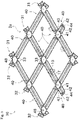
- FIG. 3 is a partial cross-sectional perspective view of the track 30 disposed in the grid area 3a.
- FIG. 4 is a partial cross-sectional perspective view of the track 30 disposed in the linear area 3b.
- the track 30 includes a plurality of the first tracks 31 and a plurality of the second tracks 32.
- the first track 31 includes rail parts 40 aligned in a longitudinal direction and crossing members 48 disposed between the rail parts 40 with an interstice 33 therebetween.
- the second track 32 also includes, in the same manner as the first track 31, rail parts 40 aligned in a longitudinal direction and crossing members 48 disposed between the rail parts 40 with an interstice 33 therebetween.
- the interstice 33 is a space for allowing the supporting body 12 to pass through when the suspension-type traveling vehicle 10 is traveling.
- the rail part 40 and the crossing member 48 are connected to each other at the upper side via another member.
- the crossing member 48 is common between the first track 31 and the second track 32.
- the rail part 40 constituting the first track 31 and the rail part 40 constituting the second track 32 have the same shape.
- the rail part 40 includes a driving wheel support member 41, an upper auxiliary wheel support member 42, a partition member 43, and a lower auxiliary wheel support member 44.
- the driving wheel support member 41 is a plate-like member disposed so that its thickness direction is the same as the vertical direction.
- the driving wheel support member 41 has a support surface on its upper surface for contacting the driving wheel 13 (in particular, the lower end of the driving wheel 13).
- the rail parts 40 (the driving wheel support members 41) are disposed so as to face each other, the arrangement interval of the rail parts 40 is the same as that of the driving wheel 13.
- the upper auxiliary wheel support member 42 is formed to extend upward from an upper surface of the driving wheel support member 41.
- the upper auxiliary wheel support member 42 has a support surface on its upper surface for contacting the upper auxiliary wheel 17 (in particular, the lower end of the upper auxiliary wheel 17). Since the suspension-type traveling vehicle 10 includes the upper auxiliary wheel 17 in addition to the driving wheel 13, the suspension-type traveling vehicle 10 can be more stably supported.
- One rail part 40 is used both when traveling on one side (one side in a short direction) of the rail part 40 and when traveling on the other side (the other side in the short direction) of the rail part 40.
- one rail part 40 includes the two upper auxiliary wheel support members 42.
- a partition member 43 is disposed between the two upper auxiliary wheel support members 42.
- the lower auxiliary wheel support member 44 is formed to extend downward from a lower surface of the driving wheel support member 41.
- the lower auxiliary wheel support member 44 has a support surface on its side surface for contacting the lower auxiliary wheel 18 (in particular, the radial end of the lower auxiliary wheel 18).
- the lower auxiliary wheel 18 allows the suspension-type traveling vehicle 10 to travel smoothly along the track 30.
- One surface of the lower auxiliary wheel support member 44 is used as the contact surface when traveling on one side (one side in a short direction) of the rail part 40, and the other surface of the lower auxiliary wheel support member 44 is used as the contact surface when traveling on the other side (the other side in the short direction) of the rail part 40.
- the traveling area 3 of the suspension-type traveling vehicle 10 includes the grid area 3a and the linear area 3b as described above.
- the first track 31 and the second track 32 are disposed in a grid pattern.
- the first tracks 31 are disposed at an equal interval in which the suspension-type traveling vehicle 10 can travel between the first tracks 31, and the second tracks 32 are disposed at an equal interval in which the suspension-type traveling vehicle 10 can travel between the second tracks 32.
- the same-shaped unit blocks are formed so as to align in the first direction and the second direction.
- the interstice 33 is formed in both the first tracks 31 and the second tracks 32 surrounding the unit block. Although there are the two first tracks 31 and the two second tracks 32 surrounding the unit block, the interstice 33 may be formed on at least one of the two first tracks 31 and at least one of the two second tracks 32. For example, at the end of the grid area 3a, there is no need to form the interstice on the first track 31 or the second track 32 of the end side.
- This configuration allows the suspension-type traveling vehicle 10 to travel in both the first direction and the second direction even when the suspension-type traveling vehicle 10 is located in any unit block. Therefore, since various routes can be realized, even when the number of suspension-type traveling vehicles 10 to be operated is large, it becomes easy to travel to a destination while avoiding each other. Since the suspension-type traveling vehicle 10 can travel in a wider area, the accommodating area 4 in which the load port 51, preservation device 52, and the like are provided below the grid area 3a can be secured in a wider area, so that a larger amount of articles can be accommodated.
- the driving wheel 13 rides over the interstice 33 every time the driving wheel 13 moves from one unit block to the next unit block.
- the suspension-type traveling vehicle 10 travels in the first direction
- the driving wheel 13 needs to ride over the interstice 33 along the second direction.
- the suspension-type traveling vehicle 10 is easily vibrated. Therefore, it is not preferable to move at a high speed in order to protect the semiconductor wafer accommodated in the storage container 23. Even when the semiconductor wafer is not accommodated in the storage container 23, it may not be preferable to move at high speed in order to avoid loads applied to the suspension-type traveling vehicle 10.
- the suspension-type traveling vehicle 10 can travel in various directions, it is not preferable that the suspension-type traveling vehicle 10 travels at high speed in order to reliably avoid a collision.
- the linear area 3b capable of running at high speed is provided in addition to the grid area 3a.
- the linear area 3b will be described in detail.
- the linear area 3b includes only one of the first tracks 31 and the second tracks 32.
- the traveling directions of the suspension-type traveling vehicle 10 cannot be changed between the first direction and the second direction. That is, the traveling directions are defined as the first direction or the second direction.
- the interstice 33 does not need to be formed because the traveling direction is not changed, and the interstice 33 perpendicular to the traveling direction is not formed in the linear area 3b.
- the interstice 33 along the second direction that is the interstice 33 required to move the supporting body 12 in the second direction, is not formed.
- the first track 31 or the second track 32 is constituted of a member in which the rail part 40 and the crossing member 48 of the grid area 3a are connected to each other so as to fill the interstice 33.
- the maximum speed of the linear area 3b is set higher than that of the grid area 3a.
- a detecting means for detecting the present position of the suspension-type traveling vehicle 10 a data in which the positions of the grid area 3a and the linear area 3b are stored, and a control means for controlling the speed of the suspension-type traveling vehicle 10.
- a detecting unit there is a configuration in which the suspension-type traveling vehicle 10 reads identifiers (bar code, RFID, etc.) disposed in track 30. If the present position of the suspension-type traveling vehicle 10 is in the linear area 3b, the traveling motor 14 of the suspension-type traveling vehicle 10 is controlled so as not to exceed the maximum speed set in the linear area 3b.
- This control may be performed by a control device included in the suspension-type traveling vehicle 10, by a control device that controls the conveyance system 1, or by both of the control devices cooperatively.
- the suspension-type traveling vehicle 10 cannot change the traveling direction in the linear area 3b. Furthermore, the suspension-type traveling vehicle 10 cannot enter from the grid area 3a to an intermediate portion of the linear area 3b. Thus, for example, if there is a long linear area 3b in a center of the traveling area 3, the suspension-type traveling vehicle 10 may bypass this long linear area 3b in order to reach a destination. Therefore, it is preferable that the linear area 3b is provided along an edge of the traveling area 3 as in the first embodiment. With this configuration, the linear area 3b is utilized, while preventing from interfering with the suspension-type traveling vehicle 10 which travels in the grid area 3a. However, depending on a layout of the facility, there may be no problem even if a long linear area 3b is provided in the center of traveling area 3.
- the suspension-type traveling vehicle 10 can travel in both one side of the first direction and the other side of the first direction. In this case, if the two suspension-type traveling vehicles 10 travel closer to each other along the same linear area 3b, one suspension-type traveling vehicle 10 needs to return along the linear area 3b. In order to avoid this situation, it may be defined that traveling toward one side of the first direction (or the second direction) is enabled instead of defining only the first direction (or the second direction).
- the linear area 3b along the first direction and the linear area 3b along the second direction are connected.
- a linear area 3b along only one of the first direction or the second direction may be provided.
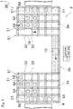
- FIG. 5 is a schematic plan view showing a configuration of a conveyance system of the second embodiment.
- members identical or similar to those of the first embodiment will be given the same reference signs on the drawings, and their description may be omitted.
- both the grid area 3a and the linear area 3b are included in one section (one bay).
- the path for connecting differing sections is configured as the linear area 3b. Since the distances between the different sections may be long and there is no need to change the traveling direction on the way, the advantages of linear area 3b can be effectively utilized.
- the two sections are connected through the one linear area 3b, but the two sections may be connected through a plurality of (e.g., two) linear areas 3b.
- efficient conveyance can be achieved.
- the conveyance system 1 of the present embodiment includes the traveling area 3 and the suspension-type traveling vehicle 10.
- the traveling area 3 is constituted of a plurality of the first tracks 31 disposed along the first direction and a plurality of the second tracks 32 disposed along the second direction perpendicular to the first direction.
- the suspension-type traveling vehicle 10 includes the supporting body 12, and travels on the traveling area 3 while being supported by the first tracks 31 or the second tracks 32 by the supporting body 12.
- the traveling area 3 includes the grid area 3a and the linear area 3b. In the grid area 3a, the plurality of the first tracks 31 are disposed side by side, and the plurality of the second tracks 32 are disposed side by side so that the first tracks 31 and the second tracks 32 intersect.
- the grid area 3 has a plurality of the unit blocks of the same shape surrounded by the first tracks 31 and the second tracks 32.
- both the first tracks 31 and the second tracks 32 surrounding the unit block are formed with an interstice 33 for passing the supporting body 12, and the interstice 33 is perpendicular to the longitudinal direction of each track (the first track 31 or the second track 32).
- the traveling direction is configured to be equal to the first direction or the second direction in the liner area 3b, and the interstice 33 perpendicular to the traveling direction is not formed in the linear area 3b.
- the present invention includes the linear area 3b in addition to the grid area 3a.
- the suspension-type traveling vehicle 10 can travel only in a predetermined travel direction in the linear area 3b, no other suspension-type traveling vehicle 10 enters the linear area 3b from a direction crossing the travel direction. Therefore, since the possibility of collision of the suspension-type traveling vehicles 10 is extremely low in the linear area 3b, the suspension-type traveling vehicle 10 can be allowed to travel at high speed. In particular, since the interstice 33 perpendicular to the traveling direction is not formed in the linear area 3b, the vibration in the linear area 3b of the suspension-type traveling vehicle 10 during the traveling are reduced. Therefore, in the linear area 3b, even when an article which is vulnerable to vibration is conveyed, the suspension-type traveling vehicle 10 can be allowed to travel at high speed.
- maximum traveling speed of the suspension-type traveling vehicle 10 in the linear area 3b is faster than maximum traveling speed of the suspension-type traveling vehicle 10 in the grid area 3a.
- the suspension-type traveling vehicle 10 travels while suspending an article to be conveyed.
- the accommodating area 4 for accommodating the article is provided below the grid area 3a.
- a space below the grid area 3a can be utilized.
- the space below the grid area 3a can be more effectively utilized.
- the article is the storage container 23 for storing the semiconductor wafer.
- the accommodating area 4 is provided with the load port 51 where the semiconductor wafer is transferred to the processing device 50 that processes the semiconductor wafer, or the preservation device 52 for temporarily storing the storage container 23 to be transferred the semiconductor wafer to the load port 51.
- the accommodating area 4 is provided with the load port or the preservation device, so the space below the grid area can be effectively utilized.
- the interval of the driving wheels 13 in the first direction and the interval of the driving wheels 13 in the second direction of the suspension-type traveling vehicle 10 are the same. Therefore, since the interval between the first tracks 31 and the interval between the second tracks 32 are the same, the unit block is a square. Alternatively, the interval of the driving wheels 13 in the first direction and the interval of driving wheels 13 in the second direction of suspension-type traveling vehicle 10 may be different. In this case, since the interval between the first tracks 31 and the interval between the second tracks 32 are different, the unit block is a rectangular shape.
- the linear area 3b along the first direction is provided with a pair of the first tracks 31 disposed in parallel.
- a reinforcing member for connecting the pair of the first tracks 31 may be disposed. In this case, in order to secure a space for passing the supporting body 12, it is necessary to form a interstice between the reinforcing member and the first track 31 as necessary.
- the conveyance system disposed in the semiconductor manufacturing facility is described.
- the conveyance system of the present invention may be disposed in other facilities.
Landscapes
- Engineering & Computer Science (AREA)
- Mechanical Engineering (AREA)
- Transportation (AREA)
- Container, Conveyance, Adherence, Positioning, Of Wafer (AREA)
- Warehouses Or Storage Devices (AREA)
- Platform Screen Doors And Railroad Systems (AREA)
- Carriers, Traveling Bodies, And Overhead Traveling Cranes (AREA)
Claims (4)
- Fördersystem, umfassend :einen Bewegungsbereich (3), der aus einer Vielzahl von ersten Spuren (31), die entlang einer ersten Richtung angeordnet sind, und einer Vielzahl von zweiten Spuren (32), die entlang einer zweiten Richtung senkrecht zur ersten Richtung angeordnet sind, gebildet ist; undeinem sich bewegenden Fahrzeug (10) vom Aufhängungstyp, das einen Stützkörper (12) aufweist und sich auf dem Bewegungsbereich bewegt, während es von der ersten Spur oder der zweiten Spur durch den Stützkörper gestützt wird, wobei der Bewegungsbereich (3) einen Gitterbereich (3a) umfasst, in dem die Mehrzahl der ersten Spuren nebeneinander angeordnet ist und die Mehrzahl der zweiten Spuren nebeneinander angeordnet ist, so dass sich die ersten Spuren und die zweiten Spuren kreuzen, und dadurch eine Vielzahl von Einheitsblöcken der gleichen Form aufweist, die von den ersten Spuren und den zweiten Spuren umgeben sind,wobei sowohl die ersten Spuren als auch die zweiten Spuren, die die Einheitsblöcke umgeben, mit einem Zwischenraum (33) gebildet sind, der senkrecht zur Längsrichtung jeder Spur verläuft, um den Stützkörper zu passieren,einem linearen Bereich (3b), in dem eine Bewegungsrichtung gleich der ersten Richtung oder der zweiten Richtung ausgebildet ist und in dem ein Zwischenraum senkrecht zur Bewegungsrichtung nicht ausgebildet ist.
- Fördersystem nach Anspruch 1, wobei das Fördersystem derart ausgebildet ist, dass eine maximale Bewegungsgeschwindigkeit des sich bewegenden Fahrzeugs vom Aufhängungstyp in dem linearen Bereich höher ist als eine maximale Bewegungsgeschwindigkeit des sich bewegenden Fahrzeugs vom Aufhängungstyp in dem Gitterbereich.
- Fördersystem nach Anspruch 1 oder 2, wobei das sich bewegende Fahrzeug vom Aufhängungstyp derart ausgebildet ist, dass es sich bewegt, während es einen zu befördernden Artikel aufhängt, und
ein Aufnahmebereich (4) zur Aufnahme des Artikels unterhalb des Gitterbereichs vorgesehen ist. - Fördersystem nach Anspruch 3, wobei es sich bei dem Artikel um einen Lagerbehälter zum Lagern eines Halbleiterwafers handelt und
der Aufnahmebereich mit einer Ladeöffnung versehen ist, an der der Halbleiterwafer an eine Verarbeitungsvorrichtung, die den Halbleiterwafer verarbeitet, oder eine Aufbewahrungsvorrichtung zum vorübergehenden Lagern des Lagerbehälters, der mit dem Halbleiterwafer zur Ladeöffnung transportiert wird, übergeben wird.
Applications Claiming Priority (2)
| Application Number | Priority Date | Filing Date | Title |
|---|---|---|---|
| JP2017210120A JP6906754B2 (ja) | 2017-10-31 | 2017-10-31 | 搬送システム |
| PCT/JP2018/035282 WO2019087618A1 (ja) | 2017-10-31 | 2018-09-25 | 搬送システム |
Publications (3)
| Publication Number | Publication Date |
|---|---|
| EP3705422A1 EP3705422A1 (de) | 2020-09-09 |
| EP3705422A4 EP3705422A4 (de) | 2021-07-28 |
| EP3705422B1 true EP3705422B1 (de) | 2022-05-25 |
Family
ID=66333036
Family Applications (1)
| Application Number | Title | Priority Date | Filing Date |
|---|---|---|---|
| EP18873236.6A Active EP3705422B1 (de) | 2017-10-31 | 2018-09-25 | Fördersystem |
Country Status (8)
| Country | Link |
|---|---|
| US (1) | US11276596B2 (de) |
| EP (1) | EP3705422B1 (de) |
| JP (1) | JP6906754B2 (de) |
| KR (1) | KR102308078B1 (de) |
| CN (1) | CN111225864B (de) |
| SG (1) | SG11202003459PA (de) |
| TW (1) | TWI752271B (de) |
| WO (1) | WO2019087618A1 (de) |
Families Citing this family (22)
| Publication number | Priority date | Publication date | Assignee | Title |
|---|---|---|---|---|
| IL282630B (en) * | 2018-10-29 | 2022-08-01 | Murata Machinery Ltd | Car travel system |
| GB201904827D0 (en) * | 2018-11-14 | 2019-05-22 | Ocado Innovation Ltd | Container-manoeuvring apparatus |
| KR102686321B1 (ko) * | 2019-06-20 | 2024-07-19 | 무라다기카이가부시끼가이샤 | 반송차 |
| EP3985468B1 (de) * | 2019-07-12 | 2025-12-24 | Murata Machinery, Ltd. | Reisefahrzeugsystem und verfahren zur reisefahrzeugsteuerung |
| JP2021045334A (ja) * | 2019-09-18 | 2021-03-25 | 村田機械株式会社 | 作業用補助具 |
| WO2021053978A1 (ja) * | 2019-09-18 | 2021-03-25 | 村田機械株式会社 | 搬送システム及び保管部 |
| JP7351348B2 (ja) * | 2019-11-07 | 2023-09-27 | 村田機械株式会社 | 搬送システム及びグリッドシステム |
| JP7471743B2 (ja) * | 2019-11-20 | 2024-04-22 | 株式会社ディスコ | 搬送路 |
| GB202003054D0 (en) * | 2020-03-03 | 2020-04-15 | Ocado Innovation Ltd | A grid framework structure |
| NO346249B1 (en) * | 2020-03-31 | 2022-05-09 | Autostore Tech As | Section based speed reduction |
| WO2021229436A1 (en) * | 2020-05-11 | 2021-11-18 | Dedramec S.R.L. | Machinery for the movement of objects |
| JP7318811B2 (ja) * | 2020-05-19 | 2023-08-01 | 村田機械株式会社 | 天井搬送システム |
| DE102020117495A1 (de) | 2020-07-02 | 2022-01-05 | Nedcon B.V. | Warenlager für das Ein- und Auslagern von auf Ladungsträgern angeordneten Waren oder Warengebinden |
| GB202016081D0 (en) * | 2020-08-14 | 2020-11-25 | Ocado Innovation Ltd | Track assembly for a storage system |
| CN116457262B (zh) * | 2020-11-13 | 2025-04-15 | 村田机械株式会社 | 行驶车系统 |
| CN114524208B (zh) * | 2020-11-23 | 2024-04-19 | 北京极智嘉科技股份有限公司 | 一种取箱方法及取箱设备 |
| EP4261155A4 (de) * | 2020-12-10 | 2024-12-18 | Murata Machinery, Ltd. | Fördersystem |
| JP7359321B2 (ja) * | 2021-01-05 | 2023-10-11 | 村田機械株式会社 | 天井保管システム |
| US12583674B2 (en) | 2021-01-05 | 2026-03-24 | Murata Machinery, Ltd. | Overhead storage system |
| KR20230169269A (ko) * | 2021-06-03 | 2023-12-15 | 무라다기카이가부시끼가이샤 | 주행차 시스템, 단위 유닛 및 격자 형상 궤도 |
| KR102745312B1 (ko) * | 2022-03-15 | 2024-12-23 | 현대무벡스 주식회사 | 물품 이송 장치 |
| US20230416994A1 (en) * | 2022-06-24 | 2023-12-28 | Taiwan Semiconductor Manufacturing Company, Ltd. | Rail system for wafer transportation |
Family Cites Families (20)
| Publication number | Priority date | Publication date | Assignee | Title |
|---|---|---|---|---|
| JPH10299280A (ja) * | 1997-04-21 | 1998-11-10 | Daiwa Kosan Kk | 自動車・荷物等の立体格納装置 |
| TWI233913B (en) * | 2002-06-06 | 2005-06-11 | Murata Machinery Ltd | Automated guided vehicle system |
| JP4360361B2 (ja) * | 2005-08-18 | 2009-11-11 | 村田機械株式会社 | 搬送車の軌道 |
| JP2007217078A (ja) * | 2006-02-14 | 2007-08-30 | Asyst Shinko Inc | 方向転換装置 |
| US7850412B2 (en) * | 2006-09-25 | 2010-12-14 | Bec Companies, Inc. | Overhead boat storage system |
| JP5317132B2 (ja) * | 2010-12-03 | 2013-10-16 | ニチユ三菱フォークリフト株式会社 | 自動倉庫 |
| JP5630661B2 (ja) * | 2011-12-19 | 2014-11-26 | 株式会社ダイフク | 天井設置型の物品搬送設備 |
| NO334806B1 (no) * | 2012-11-13 | 2014-06-02 | Jakob Hatteland Logistics As | Lagringssystem |
| NL2011021C2 (nl) * | 2013-06-21 | 2014-12-24 | Vanderlande Ind Bv | Systeem voor het opslaan van producthouders en werkwijze voor toepassing van een dergelijk systeem. |
| GB201314313D0 (en) * | 2013-08-09 | 2013-09-25 | Ocado Ltd | Apparatus for retrieving units from a storage system |
| KR101530028B1 (ko) * | 2013-10-18 | 2015-06-19 | 주식회사 에스에프에이 | 이송대차 시스템 |
| MY184874A (en) * | 2014-08-22 | 2021-04-28 | Bec Companies Inc | Overhead guide track systems for automated material handling |
| CN104724430B (zh) * | 2015-03-04 | 2017-06-06 | 东华大学 | 一种棋盘格式立体货架的货位排布方法 |
| JP6168476B2 (ja) | 2015-03-19 | 2017-07-26 | 村田機械株式会社 | 搬送台車と搬送台車システム |
| JP6168477B2 (ja) * | 2015-03-31 | 2017-07-26 | 村田機械株式会社 | 走行台車システム及び走行台車の走行方法 |
| KR102342280B1 (ko) * | 2015-04-15 | 2021-12-21 | 오카도 이노베이션 리미티드 | 물체 핸들링 시스템 및 방법 |
| KR102165426B1 (ko) | 2016-03-03 | 2020-10-14 | 무라다기카이가부시끼가이샤 | 반송 시스템 |
| JP6620707B2 (ja) * | 2016-09-09 | 2019-12-18 | 株式会社ダイフク | 物品搬送設備 |
| AU2017353094B2 (en) * | 2016-11-04 | 2023-11-30 | WITRON Logistik + Informatik GmbH & Co. KG | Flexible and compact order-picking system |
| KR101901029B1 (ko) * | 2016-11-29 | 2018-09-21 | 세메스 주식회사 | Oht 장치 |
-
2017
- 2017-10-31 JP JP2017210120A patent/JP6906754B2/ja active Active
-
2018
- 2018-09-25 KR KR1020207015387A patent/KR102308078B1/ko active Active
- 2018-09-25 WO PCT/JP2018/035282 patent/WO2019087618A1/ja not_active Ceased
- 2018-09-25 SG SG11202003459PA patent/SG11202003459PA/en unknown
- 2018-09-25 US US16/756,493 patent/US11276596B2/en active Active
- 2018-09-25 CN CN201880067952.1A patent/CN111225864B/zh active Active
- 2018-09-25 EP EP18873236.6A patent/EP3705422B1/de active Active
- 2018-10-12 TW TW107135989A patent/TWI752271B/zh active
Also Published As
| Publication number | Publication date |
|---|---|
| CN111225864A (zh) | 2020-06-02 |
| KR20200070395A (ko) | 2020-06-17 |
| WO2019087618A1 (ja) | 2019-05-09 |
| US11276596B2 (en) | 2022-03-15 |
| SG11202003459PA (en) | 2020-05-28 |
| TW201922547A (zh) | 2019-06-16 |
| US20200343118A1 (en) | 2020-10-29 |
| EP3705422A4 (de) | 2021-07-28 |
| CN111225864B (zh) | 2021-06-15 |
| TWI752271B (zh) | 2022-01-11 |
| JP2019081639A (ja) | 2019-05-30 |
| JP6906754B2 (ja) | 2021-07-21 |
| KR102308078B1 (ko) | 2021-09-30 |
| EP3705422A1 (de) | 2020-09-09 |
Similar Documents
| Publication | Publication Date | Title |
|---|---|---|
| EP3705422A1 (de) | Fördersystem | |
| JP5590422B2 (ja) | 物品搬送設備 | |
| JP6946965B2 (ja) | 搬送システム | |
| US12384620B2 (en) | Overhead carrier and overhead carrying system | |
| JP6769336B2 (ja) | 物品搬送車 | |
| JP7323059B2 (ja) | 搬送車システム | |
| JP4470576B2 (ja) | 搬送システム | |
| EP3988474A1 (de) | Förderfahrzeug | |
| CN110603632B (zh) | 保管系统 | |
| CN101104473A (zh) | 物品贮存装置 | |
| JP7304389B2 (ja) | 製造工場の物品搬送システム | |
| JP7845508B2 (ja) | 搬送車システム | |
| KR20230103869A (ko) | 물품 반송 차량, 레일 구조체, 및 이를 포함하는 물품 반송 시스템 | |
| JP7559999B2 (ja) | 搬送システム | |
| KR20090009529A (ko) | 물품 수납 장치 | |
| KR102702319B1 (ko) | 물품 반송 시스템에서 반송 차량의 구동을 제어하기 위한 장치 및 방법 | |
| JPH07228344A (ja) | トンネル搬送方法及び装置 | |
| KR100309458B1 (ko) | 자동 반송 장치 | |
| CN116409636A (zh) | 物品搬运车辆、轨道结构体以及包括其的物品搬运系统 | |
| WO2026088517A1 (ja) | 走行車システム | |
| JP2000109212A (ja) | レール走行式工程間搬送装置 | |
| JP2004352376A (ja) | 搬送システム |
Legal Events
| Date | Code | Title | Description |
|---|---|---|---|
| STAA | Information on the status of an ep patent application or granted ep patent |
Free format text: STATUS: THE INTERNATIONAL PUBLICATION HAS BEEN MADE |
|
| PUAI | Public reference made under article 153(3) epc to a published international application that has entered the european phase |
Free format text: ORIGINAL CODE: 0009012 |
|
| STAA | Information on the status of an ep patent application or granted ep patent |
Free format text: STATUS: REQUEST FOR EXAMINATION WAS MADE |
|
| 17P | Request for examination filed |
Effective date: 20200421 |
|
| AK | Designated contracting states |
Kind code of ref document: A1 Designated state(s): AL AT BE BG CH CY CZ DE DK EE ES FI FR GB GR HR HU IE IS IT LI LT LU LV MC MK MT NL NO PL PT RO RS SE SI SK SM TR |
|
| AX | Request for extension of the european patent |
Extension state: BA ME |
|
| DAV | Request for validation of the european patent (deleted) | ||
| DAX | Request for extension of the european patent (deleted) | ||
| A4 | Supplementary search report drawn up and despatched |
Effective date: 20210628 |
|
| RIC1 | Information provided on ipc code assigned before grant |
Ipc: B65G 1/04 20060101AFI20210622BHEP Ipc: H01L 21/677 20060101ALI20210622BHEP |
|
| GRAP | Despatch of communication of intention to grant a patent |
Free format text: ORIGINAL CODE: EPIDOSNIGR1 |
|
| STAA | Information on the status of an ep patent application or granted ep patent |
Free format text: STATUS: GRANT OF PATENT IS INTENDED |
|
| INTG | Intention to grant announced |
Effective date: 20220103 |
|
| GRAJ | Information related to disapproval of communication of intention to grant by the applicant or resumption of examination proceedings by the epo deleted |
Free format text: ORIGINAL CODE: EPIDOSDIGR1 |
|
| STAA | Information on the status of an ep patent application or granted ep patent |
Free format text: STATUS: REQUEST FOR EXAMINATION WAS MADE |
|
| GRAP | Despatch of communication of intention to grant a patent |
Free format text: ORIGINAL CODE: EPIDOSNIGR1 |
|
| STAA | Information on the status of an ep patent application or granted ep patent |
Free format text: STATUS: GRANT OF PATENT IS INTENDED |
|
| INTC | Intention to grant announced (deleted) | ||
| GRAS | Grant fee paid |
Free format text: ORIGINAL CODE: EPIDOSNIGR3 |
|
| GRAA | (expected) grant |
Free format text: ORIGINAL CODE: 0009210 |
|
| STAA | Information on the status of an ep patent application or granted ep patent |
Free format text: STATUS: THE PATENT HAS BEEN GRANTED |
|
| INTG | Intention to grant announced |
Effective date: 20220411 |
|
| AK | Designated contracting states |
Kind code of ref document: B1 Designated state(s): AL AT BE BG CH CY CZ DE DK EE ES FI FR GB GR HR HU IE IS IT LI LT LU LV MC MK MT NL NO PL PT RO RS SE SI SK SM TR |
|
| REG | Reference to a national code |
Ref country code: GB Ref legal event code: FG4D |
|
| REG | Reference to a national code |
Ref country code: CH Ref legal event code: EP |
|
| REG | Reference to a national code |
Ref country code: DE Ref legal event code: R096 Ref document number: 602018036063 Country of ref document: DE |
|
| REG | Reference to a national code |
Ref country code: AT Ref legal event code: REF Ref document number: 1494181 Country of ref document: AT Kind code of ref document: T Effective date: 20220615 |
|
| REG | Reference to a national code |
Ref country code: IE Ref legal event code: FG4D |
|
| REG | Reference to a national code |
Ref country code: LT Ref legal event code: MG9D |
|
| REG | Reference to a national code |
Ref country code: NL Ref legal event code: MP Effective date: 20220525 |
|
| REG | Reference to a national code |
Ref country code: AT Ref legal event code: MK05 Ref document number: 1494181 Country of ref document: AT Kind code of ref document: T Effective date: 20220525 |
|
| PG25 | Lapsed in a contracting state [announced via postgrant information from national office to epo] |
Ref country code: SE Free format text: LAPSE BECAUSE OF FAILURE TO SUBMIT A TRANSLATION OF THE DESCRIPTION OR TO PAY THE FEE WITHIN THE PRESCRIBED TIME-LIMIT Effective date: 20220525 Ref country code: PT Free format text: LAPSE BECAUSE OF FAILURE TO SUBMIT A TRANSLATION OF THE DESCRIPTION OR TO PAY THE FEE WITHIN THE PRESCRIBED TIME-LIMIT Effective date: 20220926 Ref country code: NO Free format text: LAPSE BECAUSE OF FAILURE TO SUBMIT A TRANSLATION OF THE DESCRIPTION OR TO PAY THE FEE WITHIN THE PRESCRIBED TIME-LIMIT Effective date: 20220825 Ref country code: NL Free format text: LAPSE BECAUSE OF FAILURE TO SUBMIT A TRANSLATION OF THE DESCRIPTION OR TO PAY THE FEE WITHIN THE PRESCRIBED TIME-LIMIT Effective date: 20220525 Ref country code: LT Free format text: LAPSE BECAUSE OF FAILURE TO SUBMIT A TRANSLATION OF THE DESCRIPTION OR TO PAY THE FEE WITHIN THE PRESCRIBED TIME-LIMIT Effective date: 20220525 Ref country code: HR Free format text: LAPSE BECAUSE OF FAILURE TO SUBMIT A TRANSLATION OF THE DESCRIPTION OR TO PAY THE FEE WITHIN THE PRESCRIBED TIME-LIMIT Effective date: 20220525 Ref country code: GR Free format text: LAPSE BECAUSE OF FAILURE TO SUBMIT A TRANSLATION OF THE DESCRIPTION OR TO PAY THE FEE WITHIN THE PRESCRIBED TIME-LIMIT Effective date: 20220826 Ref country code: FI Free format text: LAPSE BECAUSE OF FAILURE TO SUBMIT A TRANSLATION OF THE DESCRIPTION OR TO PAY THE FEE WITHIN THE PRESCRIBED TIME-LIMIT Effective date: 20220525 Ref country code: ES Free format text: LAPSE BECAUSE OF FAILURE TO SUBMIT A TRANSLATION OF THE DESCRIPTION OR TO PAY THE FEE WITHIN THE PRESCRIBED TIME-LIMIT Effective date: 20220525 Ref country code: BG Free format text: LAPSE BECAUSE OF FAILURE TO SUBMIT A TRANSLATION OF THE DESCRIPTION OR TO PAY THE FEE WITHIN THE PRESCRIBED TIME-LIMIT Effective date: 20220825 Ref country code: AT Free format text: LAPSE BECAUSE OF FAILURE TO SUBMIT A TRANSLATION OF THE DESCRIPTION OR TO PAY THE FEE WITHIN THE PRESCRIBED TIME-LIMIT Effective date: 20220525 |
|
| PG25 | Lapsed in a contracting state [announced via postgrant information from national office to epo] |
Ref country code: RS Free format text: LAPSE BECAUSE OF FAILURE TO SUBMIT A TRANSLATION OF THE DESCRIPTION OR TO PAY THE FEE WITHIN THE PRESCRIBED TIME-LIMIT Effective date: 20220525 Ref country code: PL Free format text: LAPSE BECAUSE OF FAILURE TO SUBMIT A TRANSLATION OF THE DESCRIPTION OR TO PAY THE FEE WITHIN THE PRESCRIBED TIME-LIMIT Effective date: 20220525 Ref country code: LV Free format text: LAPSE BECAUSE OF FAILURE TO SUBMIT A TRANSLATION OF THE DESCRIPTION OR TO PAY THE FEE WITHIN THE PRESCRIBED TIME-LIMIT Effective date: 20220525 Ref country code: IS Free format text: LAPSE BECAUSE OF FAILURE TO SUBMIT A TRANSLATION OF THE DESCRIPTION OR TO PAY THE FEE WITHIN THE PRESCRIBED TIME-LIMIT Effective date: 20220925 |
|
| PG25 | Lapsed in a contracting state [announced via postgrant information from national office to epo] |
Ref country code: SM Free format text: LAPSE BECAUSE OF FAILURE TO SUBMIT A TRANSLATION OF THE DESCRIPTION OR TO PAY THE FEE WITHIN THE PRESCRIBED TIME-LIMIT Effective date: 20220525 Ref country code: SK Free format text: LAPSE BECAUSE OF FAILURE TO SUBMIT A TRANSLATION OF THE DESCRIPTION OR TO PAY THE FEE WITHIN THE PRESCRIBED TIME-LIMIT Effective date: 20220525 Ref country code: RO Free format text: LAPSE BECAUSE OF FAILURE TO SUBMIT A TRANSLATION OF THE DESCRIPTION OR TO PAY THE FEE WITHIN THE PRESCRIBED TIME-LIMIT Effective date: 20220525 Ref country code: EE Free format text: LAPSE BECAUSE OF FAILURE TO SUBMIT A TRANSLATION OF THE DESCRIPTION OR TO PAY THE FEE WITHIN THE PRESCRIBED TIME-LIMIT Effective date: 20220525 Ref country code: DK Free format text: LAPSE BECAUSE OF FAILURE TO SUBMIT A TRANSLATION OF THE DESCRIPTION OR TO PAY THE FEE WITHIN THE PRESCRIBED TIME-LIMIT Effective date: 20220525 Ref country code: CZ Free format text: LAPSE BECAUSE OF FAILURE TO SUBMIT A TRANSLATION OF THE DESCRIPTION OR TO PAY THE FEE WITHIN THE PRESCRIBED TIME-LIMIT Effective date: 20220525 |
|
| REG | Reference to a national code |
Ref country code: DE Ref legal event code: R097 Ref document number: 602018036063 Country of ref document: DE |
|
| PG25 | Lapsed in a contracting state [announced via postgrant information from national office to epo] |
Ref country code: AL Free format text: LAPSE BECAUSE OF FAILURE TO SUBMIT A TRANSLATION OF THE DESCRIPTION OR TO PAY THE FEE WITHIN THE PRESCRIBED TIME-LIMIT Effective date: 20220525 |
|
| PLBE | No opposition filed within time limit |
Free format text: ORIGINAL CODE: 0009261 |
|
| STAA | Information on the status of an ep patent application or granted ep patent |
Free format text: STATUS: NO OPPOSITION FILED WITHIN TIME LIMIT |
|
| PG25 | Lapsed in a contracting state [announced via postgrant information from national office to epo] |
Ref country code: MC Free format text: LAPSE BECAUSE OF FAILURE TO SUBMIT A TRANSLATION OF THE DESCRIPTION OR TO PAY THE FEE WITHIN THE PRESCRIBED TIME-LIMIT Effective date: 20220525 |
|
| REG | Reference to a national code |
Ref country code: CH Ref legal event code: PL |
|
| 26N | No opposition filed |
Effective date: 20230228 |
|
| GBPC | Gb: european patent ceased through non-payment of renewal fee |
Effective date: 20220925 |
|
| REG | Reference to a national code |
Ref country code: BE Ref legal event code: MM Effective date: 20220930 |
|
| PG25 | Lapsed in a contracting state [announced via postgrant information from national office to epo] |
Ref country code: SI Free format text: LAPSE BECAUSE OF FAILURE TO SUBMIT A TRANSLATION OF THE DESCRIPTION OR TO PAY THE FEE WITHIN THE PRESCRIBED TIME-LIMIT Effective date: 20220525 |
|
| PG25 | Lapsed in a contracting state [announced via postgrant information from national office to epo] |
Ref country code: LU Free format text: LAPSE BECAUSE OF NON-PAYMENT OF DUE FEES Effective date: 20220925 |
|
| PG25 | Lapsed in a contracting state [announced via postgrant information from national office to epo] |
Ref country code: LI Free format text: LAPSE BECAUSE OF NON-PAYMENT OF DUE FEES Effective date: 20220930 Ref country code: IE Free format text: LAPSE BECAUSE OF NON-PAYMENT OF DUE FEES Effective date: 20220925 Ref country code: FR Free format text: LAPSE BECAUSE OF NON-PAYMENT OF DUE FEES Effective date: 20220930 Ref country code: CH Free format text: LAPSE BECAUSE OF NON-PAYMENT OF DUE FEES Effective date: 20220930 |
|
| PG25 | Lapsed in a contracting state [announced via postgrant information from national office to epo] |
Ref country code: BE Free format text: LAPSE BECAUSE OF NON-PAYMENT OF DUE FEES Effective date: 20220930 |
|
| PG25 | Lapsed in a contracting state [announced via postgrant information from national office to epo] |
Ref country code: GB Free format text: LAPSE BECAUSE OF NON-PAYMENT OF DUE FEES Effective date: 20220925 |
|
| PG25 | Lapsed in a contracting state [announced via postgrant information from national office to epo] |
Ref country code: IT Free format text: LAPSE BECAUSE OF FAILURE TO SUBMIT A TRANSLATION OF THE DESCRIPTION OR TO PAY THE FEE WITHIN THE PRESCRIBED TIME-LIMIT Effective date: 20220525 |
|
| PG25 | Lapsed in a contracting state [announced via postgrant information from national office to epo] |
Ref country code: CY Free format text: LAPSE BECAUSE OF FAILURE TO SUBMIT A TRANSLATION OF THE DESCRIPTION OR TO PAY THE FEE WITHIN THE PRESCRIBED TIME-LIMIT Effective date: 20220525 |
|
| PG25 | Lapsed in a contracting state [announced via postgrant information from national office to epo] |
Ref country code: MK Free format text: LAPSE BECAUSE OF FAILURE TO SUBMIT A TRANSLATION OF THE DESCRIPTION OR TO PAY THE FEE WITHIN THE PRESCRIBED TIME-LIMIT Effective date: 20220525 Ref country code: HU Free format text: LAPSE BECAUSE OF FAILURE TO SUBMIT A TRANSLATION OF THE DESCRIPTION OR TO PAY THE FEE WITHIN THE PRESCRIBED TIME-LIMIT; INVALID AB INITIO Effective date: 20180925 |
|
| PG25 | Lapsed in a contracting state [announced via postgrant information from national office to epo] |
Ref country code: MT Free format text: LAPSE BECAUSE OF FAILURE TO SUBMIT A TRANSLATION OF THE DESCRIPTION OR TO PAY THE FEE WITHIN THE PRESCRIBED TIME-LIMIT Effective date: 20220525 |
|
| PG25 | Lapsed in a contracting state [announced via postgrant information from national office to epo] |
Ref country code: BG Free format text: LAPSE BECAUSE OF FAILURE TO SUBMIT A TRANSLATION OF THE DESCRIPTION OR TO PAY THE FEE WITHIN THE PRESCRIBED TIME-LIMIT Effective date: 20220525 |
|
| PG25 | Lapsed in a contracting state [announced via postgrant information from national office to epo] |
Ref country code: BG Free format text: LAPSE BECAUSE OF FAILURE TO SUBMIT A TRANSLATION OF THE DESCRIPTION OR TO PAY THE FEE WITHIN THE PRESCRIBED TIME-LIMIT Effective date: 20220525 |
|
| PGFP | Annual fee paid to national office [announced via postgrant information from national office to epo] |
Ref country code: DE Payment date: 20250820 Year of fee payment: 8 |
|
| PG25 | Lapsed in a contracting state [announced via postgrant information from national office to epo] |
Ref country code: TR Free format text: LAPSE BECAUSE OF FAILURE TO SUBMIT A TRANSLATION OF THE DESCRIPTION OR TO PAY THE FEE WITHIN THE PRESCRIBED TIME-LIMIT Effective date: 20220525 |