EP3703167B1 - Bauteil zur messung der druckänderung in einer pouch-batterie und verfahren zur messung der druckänderung in pouch-batterien damit - Google Patents
Bauteil zur messung der druckänderung in einer pouch-batterie und verfahren zur messung der druckänderung in pouch-batterien damit Download PDFInfo
- Publication number
- EP3703167B1 EP3703167B1 EP18871488.5A EP18871488A EP3703167B1 EP 3703167 B1 EP3703167 B1 EP 3703167B1 EP 18871488 A EP18871488 A EP 18871488A EP 3703167 B1 EP3703167 B1 EP 3703167B1
- Authority
- EP
- European Patent Office
- Prior art keywords
- type battery
- fixing unit
- pouch type
- pressure change
- connecting pipe
- Prior art date
- Legal status (The legal status is an assumption and is not a legal conclusion. Google has not performed a legal analysis and makes no representation as to the accuracy of the status listed.)
- Active
Links
Images


Classifications
-
- H—ELECTRICITY
- H01—ELECTRIC ELEMENTS
- H01M—PROCESSES OR MEANS, e.g. BATTERIES, FOR THE DIRECT CONVERSION OF CHEMICAL ENERGY INTO ELECTRICAL ENERGY
- H01M50/00—Constructional details or processes of manufacture of the non-active parts of electrochemical cells other than fuel cells, e.g. hybrid cells
- H01M50/30—Arrangements for facilitating escape of gases
-
- G—PHYSICS
- G01—MEASURING; TESTING
- G01L—MEASURING FORCE, STRESS, TORQUE, WORK, MECHANICAL POWER, MECHANICAL EFFICIENCY, OR FLUID PRESSURE
- G01L19/00—Details of, or accessories for, apparatus for measuring steady or quasi-steady pressure of a fluent medium insofar as such details or accessories are not special to particular types of pressure gauges
- G01L19/0007—Fluidic connecting means
- G01L19/003—Fluidic connecting means using a detachable interface or adapter between the process medium and the pressure gauge
-
- G—PHYSICS
- G01—MEASURING; TESTING
- G01N—INVESTIGATING OR ANALYSING MATERIALS BY DETERMINING THEIR CHEMICAL OR PHYSICAL PROPERTIES
- G01N1/00—Sampling; Preparing specimens for investigation
- G01N1/02—Devices for withdrawing samples
- G01N1/22—Devices for withdrawing samples in the gaseous state
-
- G—PHYSICS
- G01—MEASURING; TESTING
- G01N—INVESTIGATING OR ANALYSING MATERIALS BY DETERMINING THEIR CHEMICAL OR PHYSICAL PROPERTIES
- G01N7/00—Analysing materials by measuring the pressure or volume of a gas or vapour
-
- G—PHYSICS
- G01—MEASURING; TESTING
- G01N—INVESTIGATING OR ANALYSING MATERIALS BY DETERMINING THEIR CHEMICAL OR PHYSICAL PROPERTIES
- G01N7/00—Analysing materials by measuring the pressure or volume of a gas or vapour
- G01N7/10—Analysing materials by measuring the pressure or volume of a gas or vapour by allowing diffusion of components through a porous wall and measuring a pressure or volume difference
-
- G—PHYSICS
- G01—MEASURING; TESTING
- G01N—INVESTIGATING OR ANALYSING MATERIALS BY DETERMINING THEIR CHEMICAL OR PHYSICAL PROPERTIES
- G01N7/00—Analysing materials by measuring the pressure or volume of a gas or vapour
- G01N7/14—Analysing materials by measuring the pressure or volume of a gas or vapour by allowing the material to emit a gas or vapour, e.g. water vapour, and measuring a pressure or volume difference
-
- H—ELECTRICITY
- H01—ELECTRIC ELEMENTS
- H01M—PROCESSES OR MEANS, e.g. BATTERIES, FOR THE DIRECT CONVERSION OF CHEMICAL ENERGY INTO ELECTRICAL ENERGY
- H01M10/00—Secondary cells; Manufacture thereof
- H01M10/04—Construction or manufacture in general
- H01M10/049—Processes for forming or storing electrodes in the battery container
-
- H—ELECTRICITY
- H01—ELECTRIC ELEMENTS
- H01M—PROCESSES OR MEANS, e.g. BATTERIES, FOR THE DIRECT CONVERSION OF CHEMICAL ENERGY INTO ELECTRICAL ENERGY
- H01M10/00—Secondary cells; Manufacture thereof
- H01M10/42—Methods or arrangements for servicing or maintenance of secondary cells or secondary half-cells
- H01M10/48—Accumulators combined with arrangements for measuring, testing or indicating the condition of cells, e.g. the level or density of the electrolyte
-
- H—ELECTRICITY
- H01—ELECTRIC ELEMENTS
- H01M—PROCESSES OR MEANS, e.g. BATTERIES, FOR THE DIRECT CONVERSION OF CHEMICAL ENERGY INTO ELECTRICAL ENERGY
- H01M4/00—Electrodes
- H01M4/02—Electrodes composed of, or comprising, active material
- H01M4/04—Processes of manufacture in general
-
- H—ELECTRICITY
- H01—ELECTRIC ELEMENTS
- H01M—PROCESSES OR MEANS, e.g. BATTERIES, FOR THE DIRECT CONVERSION OF CHEMICAL ENERGY INTO ELECTRICAL ENERGY
- H01M4/00—Electrodes
- H01M4/02—Electrodes composed of, or comprising, active material
- H01M4/04—Processes of manufacture in general
- H01M4/0438—Processes of manufacture in general by electrochemical processing
- H01M4/044—Activating, forming or electrochemical attack of the supporting material
- H01M4/0445—Forming after manufacture of the electrode, e.g. first charge, cycling
- H01M4/0447—Forming after manufacture of the electrode, e.g. first charge, cycling of complete cells or cells stacks
-
- H—ELECTRICITY
- H01—ELECTRIC ELEMENTS
- H01M—PROCESSES OR MEANS, e.g. BATTERIES, FOR THE DIRECT CONVERSION OF CHEMICAL ENERGY INTO ELECTRICAL ENERGY
- H01M50/00—Constructional details or processes of manufacture of the non-active parts of electrochemical cells other than fuel cells, e.g. hybrid cells
- H01M50/10—Primary casings; Jackets or wrappings
- H01M50/102—Primary casings; Jackets or wrappings characterised by their shape or physical structure
- H01M50/105—Pouches or flexible bags
-
- G—PHYSICS
- G01—MEASURING; TESTING
- G01L—MEASURING FORCE, STRESS, TORQUE, WORK, MECHANICAL POWER, MECHANICAL EFFICIENCY, OR FLUID PRESSURE
- G01L19/00—Details of, or accessories for, apparatus for measuring steady or quasi-steady pressure of a fluent medium insofar as such details or accessories are not special to particular types of pressure gauges
- G01L19/0092—Pressure sensor associated with other sensors, e.g. for measuring acceleration or temperature
-
- H—ELECTRICITY
- H01—ELECTRIC ELEMENTS
- H01M—PROCESSES OR MEANS, e.g. BATTERIES, FOR THE DIRECT CONVERSION OF CHEMICAL ENERGY INTO ELECTRICAL ENERGY
- H01M2200/00—Safety devices for primary or secondary batteries
- H01M2200/20—Pressure-sensitive devices
-
- Y—GENERAL TAGGING OF NEW TECHNOLOGICAL DEVELOPMENTS; GENERAL TAGGING OF CROSS-SECTIONAL TECHNOLOGIES SPANNING OVER SEVERAL SECTIONS OF THE IPC; TECHNICAL SUBJECTS COVERED BY FORMER USPC CROSS-REFERENCE ART COLLECTIONS [XRACs] AND DIGESTS
- Y02—TECHNOLOGIES OR APPLICATIONS FOR MITIGATION OR ADAPTATION AGAINST CLIMATE CHANGE
- Y02E—REDUCTION OF GREENHOUSE GAS [GHG] EMISSIONS, RELATED TO ENERGY GENERATION, TRANSMISSION OR DISTRIBUTION
- Y02E60/00—Enabling technologies; Technologies with a potential or indirect contribution to GHG emissions mitigation
- Y02E60/10—Energy storage using batteries
-
- Y—GENERAL TAGGING OF NEW TECHNOLOGICAL DEVELOPMENTS; GENERAL TAGGING OF CROSS-SECTIONAL TECHNOLOGIES SPANNING OVER SEVERAL SECTIONS OF THE IPC; TECHNICAL SUBJECTS COVERED BY FORMER USPC CROSS-REFERENCE ART COLLECTIONS [XRACs] AND DIGESTS
- Y02—TECHNOLOGIES OR APPLICATIONS FOR MITIGATION OR ADAPTATION AGAINST CLIMATE CHANGE
- Y02P—CLIMATE CHANGE MITIGATION TECHNOLOGIES IN THE PRODUCTION OR PROCESSING OF GOODS
- Y02P70/00—Climate change mitigation technologies in the production process for final industrial or consumer products
- Y02P70/50—Manufacturing or production processes characterised by the final manufactured product
Definitions
- the present invention relates to a pouch type battery comprising a component for measuring pressure change of the pouch type battery and a method for measuring pressure change of a pouch type battery.
- the component can be installed on the pouch type battery and connected to a pressure gauge for measuring pressure change of the pouch type battery.
- the battery in order to measure pressure change of a battery, the battery is put in a box of a certain size, and let the inside of the box become vacuum. Then, the pressure change is checked by drilling a hole in the pouch side of the battery and measured by collecting the inner gas. Since this method is a method of measuring the pressure change by collecting the inner gas in a vacuum state, dissolved gas is also vaporized and it is difficult to know the actual pressure change inside the battery, and there is a problem that an electrolyte is vaporized from the battery due to the vacuum state inside the box.
- the present invention provides a pouch type battery comprising a component for measuring pressure change of the pouch type battery, the component comprising:
- the connecting pipe, the first fixing unit and the second fixing unit may be formed into a single unitary body.
- the component for measuring pressure change of a pouch type battery may further comprise a valve coupled to the upper end facing the pressure gauge of both ends of the connecting pipe and that the valve configured to control opening and closing of the connecting pipe.
- the component for measuring pressure change of a pouch type battery can be installed on the exterior layer of the pouch type battery during an initial stage of manufacturing the pouch type battery.
- the component for measuring pressure change of a pouch type battery may further comprise:
- the first sealing member may conform to a shape of a horizontal cross section of the inner surface of the third fixing unit.
- a shape of the second sealing member may be the same as a shape of the first sealing member.
- a size of a horizontal cross section of the first fixing unit may be larger than a size of a horizontal cross section of the connecting pipe, and a size of a horizontal cross section of the second fixing unit may be larger than the size of the horizontal cross section of the first fixing unit.
- the connecting pipe, the first fixing unit and the second fixing unit may be each comprised of plastic
- the third fixing unit may be comprised of plastic or metals
- the first sealing member and the second sealing member may be comprised of rubber or latex.
- the connecting pipe, the first fixing unit and the second fixing unit may be each comprised of at least one selected from the group consisting of polyethylene (PE), polypropylene (PP), Teflon and PEEK
- the third fixing unit may be comprised of at least one selected from the group consisting of stainless steel (SUS), aluminum (Al), polyethylene (PE), polypropylene (PP), Teflon and PEEK
- the first sealing member and the second sealing member may be comprised of at least one selected from the group consisting of rubber, latex, polybutadiene rubber (BR), nitrile butadiene rubber (NBR), ethylene-propylene rubber (EPM, EPDM) and silicon rubber (VMQ).
- the method for measuring pressure change of a gas generated in the pouch type battery comprises the following steps of:
- the present invention there are advantages of measuring pressure change inside a battery cell while evaluating the characteristics of the battery cell such as lifetime and storage from the initial stage of forming the battery cell by installing the component for measuring pressure change of a pouch type battery in the initial cell assembly process of the pouch type battery, and of collecting samples for gas analysis while measuring pressure change.
- the pouch type battery according to the present invention comprises:
- the connecting pipe, the first fixing unit and the second fixing unit may be formed into a single unitary body.
- the component for measuring pressure change of a pouch type battery may further comprise a valve that is combined to the upper end facing the pressure gauge of both ends of the connecting pipe and that can control opening and closing of the connecting pipe.
- the component for measuring pressure change of a pouch type battery can be installed in the exterior layer of the pouch type battery during an initial stage of manufacturing the pouch type battery.
- the component for measuring pressure change of a pouch type battery may further comprise:
- the first sealing member may correspond with the shape of the horizontal section of the inner surface of the third fixing unit.
- the shape of the second sealing member may be the same as the shape of the first sealing member.
- the size of the horizontal section of the first fixing unit may be larger than the size of the horizontal section of the connecting pipe, and the size of the horizontal section of the second fixing unit may be larger than the size of the horizontal section of the first fixing unit.
- the connecting pipe, the first fixing unit and the second fixing unit may be comprised of plastic, respectively, the third fixing unit may be comprised of plastic or metals, and the first sealing member and the second sealing member may be comprised of rubber or latex.
- the connecting pipe, the first fixing unit and the second fixing unit may be comprised of at least one selected from the group consisting of polyethylene (PE), polypropylene (PP), Teflon and PEEK, respectively
- the third fixing unit may be comprised of at least one selected from the group consisting of stainless steel (SUS), aluminum (Al), polyethylene (PE), polypropylene (PP), Teflon and PEEK
- the first sealing member and the second sealing member may be comprised of at least one selected from the group consisting of rubber, latex, polybutadiene rubber (BR), nitrile butadiene rubber (NBR), ethylene-propylene rubber (EPM, EPDM) and silicon rubber (VMQ).
- the method for measuring pressure change of gas generated from the pouch type battery comprises the following steps of:
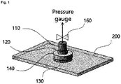
- Fig. 1 illustrates a case that the component for measuring pressure change of a pouch type battery 100 is installed on a pouch type battery 200.
- Fig. 2 and Fig. 3 are a perspective view and a front view of the component for measuring pressure change of a pouch type battery 100 of Fig. 1 , respectively.
- Fig. 1 illustrates the component for measuring pressure change of a pouch type battery 100 installed on the pouch type battery 200.
- the component for measuring pressure change of a pouch type battery 100 can be installed on the exterior layer of the pouch type battery 200, for example, from the initial cell assembly process of the pouch type battery 200.
- Fig. 1 illustrates the component for measuring pressure change of a pouch type battery 100 installed on the pouch type battery 200.
- the component for measuring pressure change of a pouch type battery 100 can be installed on the exterior layer of the pouch type battery 200, for example, from the initial cell assembly process of the pouch type battery 200.
- the component for measuring pressure change of a pouch type battery 100 can be installed on the upper face of the exterior layer of the pouch type battery 200, but if the size of the pouch type battery 200 is small or the installation of the component for measuring pressure change of a pouch type battery 100 is difficult in the initial assembly stage of the pouch type battery 200, various modifications are possible, for examples, the component may not be installed on the upper face of the exterior layer or may be installed in a gas pocket of the pouch type battery 200.
- a pressure gauge (not shown) for measuring pressure change of the pouch type battery can be directly or indirectly connected to the component for measuring pressure change of a pouch type battery 100 installed on the exterior layer of the pouch type battery 200.
- the method of inserting the battery into a box and drilling a hole in the battery to diffuse gas into the box and collect it has problems that the accuracy of pressure measurement is lowered and the accuracy of pressure measurement is further lowered as an electrolyte of the battery is vaporized into the vacuum box.
- the present invention by using a novel method of installing the component for measuring pressure change of a pouch type battery 100 on the exterior layer of the pouch type battery 200, the gas generated from the pouch type battery 200 is directly transferred to the pressure gauge so that pressure of the gas generated in the battery 200 can be accurately measured. Further, by using the component for measuring pressure change of a pouch type battery 100, sampling for analyzing the gas generated in the battery 200 is also made easy.
- Fig. 2 illustrates some components of the component for measuring pressure change of a pouch type battery 100 according to Fig. 1 .
- the component for measuring pressure change of a pouch type battery 100 comprises a connecting pipe 110 that is a passage capable of connecting the pouch type battery 200 and the pressure gauge.
- the connecting pipe 110 is located on the exterior layer of the pouch type battery 200 and has a tubular shape having a predetermined length. Accordingly, a pipe or a tube (not shown) capable of transferring the gas generated from the pouch type battery 200 to the pressure gauge can be installed on the connecting pipe 110. Or, in some cases, the pressure gauge can be directly connected to the connecting pipe 110.
- the length of the connecting pipe 110 is preferably as short as possible within a range in which the pipe or the tube (not shown) capable of transferring gas to the pressure gauge can be easily installed on the connecting pipe 110.
- the length may be 0.1 cm to 5 cm, or 0.5 cm to 3 cm.
- the overall height of the component for measuring pressure change of a pouch type battery 100 i.e., the total length including the connecting pipe 110, the first fixing unit 120, the second fixing unit 130 and a valve 160 to be described later
- the total length including the connecting pipe 110, the first fixing unit 120, the second fixing unit 130 and a valve 160 to be described later may be, for example, 1 cm to 10 cm, or 1.5 cm to 5 cm.
- One end facing the pressure gauge of the both ends of the connecting pipe 110 may further include a valve 160 capable of controlling opening and closing of the connecting pipe 110.
- the valve 160 may be a valve capable of on/off, that is, opening and closing of the connecting pipe 110, and for example, it may be a ball valve, a butterfly valve, a gate valve, a diaphragm valve and a globe valve.
- the first fixing unit 120 is connected to the other end of the connecting pipe 110 facing the pouch type battery 200 of the both ends.
- the first fixing unit 120 is integrally formed with the connecting pipe 110, and is located on the exterior layer of the pouch type battery 200.
- the first fixing unit 120 may be a tubular shape having a circular horizontal section. The upper side of the first fixing unit 120 is closed but the part connected to the connecting pipe 110 is open. The size of the horizontal section of the first fixing unit 120 may be larger than the horizontal section of the connecting pipe 110.
- the third fixing unit 140 (see Fig. 3 ) is combined to the first fixing unit 120 to prevent the component for measuring pressure change of a pouch type battery 100 from being detached from the pouch type battery 200.
- the third fixing unit 140 may be in the form of a cap that covers the upper side and the side of the first fixing unit 120, and the upper side of the third fixing unit 140 may have an opening through which the connecting pipe 110 can pass.
- the side of the outer surface of the first fixing unit 120 has a male screw shape and the side of the inner surface of the third fixing unit 140 has a female screw shape so that the male screw shape of the first fixing unit 120 and the female screw shape of the third fixing unit 140 can be geared with each other for combination.
- the female screw shape of the first fixing unit 120 and the male screw shape of the third fixing unit 140 can be geared with each other for combination.
- the side of the outer surface of the first fixing unit 120 and the side of the inner surface of the third fixing unit 140 are respectively provided with protrusions and recesses so that the protrusions and the recesses may be geared with each other for combination.
- the combination method of the first fixing unit 120 and the third fixing unit 140 is not limited to the above description, and various modifications and variations are possible.
- the connecting pipe 110 is connected to the upper side of the first fixing unit 120 to form a single unitary body
- the second fixing unit 130 is connected to the lower side of the first fixing unit 120 to form a single unitary body.
- the second fixing unit 130 may be a tubular shape having a circular horizontal section. The upper side of the second fixing unit 130 is closed but the part connected to the first fixing unit 120 is open.
- the second fixing unit 130 is located under the exterior layer of the pouch type battery 200, that is, inside the pouch type battery 200.
- an opening is formed in the exterior layer of the pouch type battery 200 so as to substantially correspond to the shape of the horizontal section of the first fixing unit 120, and then a member integrally formed with the connecting pipe 110, the first fixing unit 120 and the second fixing unit 130 is installed on the opening of the exterior layer of the pouch type battery 200.
- the connecting pipe 110 and the first fixing unit 120 are located on the exterior layer of the pouch type battery 200 (i.e., outside of the pouch type battery 200), and the second fixing unit 130 is located under the exterior layer of the pouch type battery 200 (i.e., inside the pouch type battery 200).
- the size of the horizontal section of the second fixing unit 130 may be larger than the horizontal section of the first fixing unit 120.
- the lower end of the third fixing unit 140 contacts the second fixing unit 130 through the exterior layer of the pouch type battery 200.
- detachment of the component for measuring pressure change of a pouch type battery 100 from the pouch type battery 200 can be prevented.
- the inner surface of the third fixing unit 140 is provided with the first sealing member 150a, which has elasticity and the shape corresponding to the shape of the horizontal section of the inner surface of the third fixing unit 140, such as a pad shape (see Fig. 4 ) and a ring shape.
- the second sealing member 150b which has the same or similar shape with the shape of the first sealing member 150a and also has elasticity, can be installed on the upper side of the second fixing unit 130. Accordingly, when the third fixing unit 140 is combined to the first fixing unit 120 and the second fixing unit 130, the first sealing member 150a and the second sealing member 150b are brought into close contact with each other through the exterior layer of the pouch type battery 200 to prevent the gas generated from the pouch type battery 200 from leaking to the outside. Further, it is possible to prevent the exterior layer of the pouch type battery 200 from tearing due to friction with the third fixing unit 140 or the second fixing unit 130.
- the connecting pipe 110, the first fixing unit 120 and the second fixing unit 130, which are in contact with the electrode surface of the pouch type battery 200, may be made of a plastic material and the like so as to prevent short, and for example, the material may be at least one plastic selected from the group consisting of polyethylene (PE), polypropylene (PP), Teflon and PEEK.
- the third fixing unit 140, which is located outside the pouch type battery 200, can be made of plastics, metals and the like.
- the material may be at least one selected from the group consisting of metals such as stainless steel (SUS) and aluminum (Al) and plastics such as polyethylene (PE), polypropylene (PP), Teflon and PEEK.
- the first sealing member 150a and the second sealing member 150b may be made of a material having elasticity and not soluble in the electrolyte component such as rubber and latex.
- the material may be at least one selected from the group consisting of rubber, latex, polybutadiene rubber (BR), nitrile butadiene rubber (NBR), ethylene-propylene rubber (EPM, EPDM) and silicon rubber (VMQ).
- Fig. 3 illustrates the third fixing unit 140 combined to the first fixing unit 120 and the second fixing unit 130 in the component for measuring pressure change of a pouch type battery 100 according to Fig. 1 .
- the pouch type battery 200 is not shown in Fig. 3 , but as shown in Fig. 1 , when the component for measuring pressure change of a pouch type battery 100 is installed on the pouch type battery 200, the exterior layer of the pouch type battery 200 may be located between the lower end of the third fixing unit 140 and the upper side of the second fixing unit 130.
- Fig. 4 shows an exemplary photograph of a rubber pad used as the first and the second sealing members 150a, 150b in the component for measuring pressure change of a pouch type battery of Fig. 1 .
- the component for measuring pressure change of a pouch type battery 100 is installed on the exterior layer of the pouch type battery 200 (Step 1).
- the component for measuring pressure change of a pouch type battery 100 may be installed on the upper surface of the exterior layer of the pouch type battery 200, but if the size of the pouch type battery 200 is small or it is difficult to install the component for measuring pressure change of a pouch type battery 100 in the initial assembly stage of the pouch type battery 200, the component may not be installed on the supper surface of the exterior layer.
- the component for measuring pressure change of a pouch type battery 100 can be located on the upper surface of the pouch type battery 200, but not limited to that shown in Fig. 1 .
- the component can be installed on a gas pocket of the pouch type battery 200 and various modifications and variations are possible.
- an electrolyte is injected into the opening part of the gas pocket of the pouch type battery 200 on which the component for measuring pressure change of a pouch type battery 100 is installed, edges of the upper side and the lower side of the exterior layer of the pouch type battery 200 are thermally fused to form a single unitary body, and then activation is proceeded to manufacture the pouch type battery 200 having the desired characteristics (Step 2).
- Step 2 After injecting the electrolyte to drive the pouch type battery, a certain period of time is waited for the electrolyte to be wetted to the electrode, and then a voltage is slowly applied to form a passage through which lithium (Li) ions are transferred from the positive electrode to the negative electrode.
- the pouch type battery 200 on which the component for measuring pressure change of a pouch type battery 100 is installed is manufactured by the conventional method of manufacturing a pouch type battery.
- the pressure gauge is connected to the connecting unit 110 of the component for measuring pressure change of a pouch type battery 100 to measure pressure change under the desired experimental conditions (Step 3). Namely, after the activation of the pouch type battery 200 in the step 2, the gas generated inside the pouch type battery 200 can be collected through the component for measuring pressure change of a pouch type battery 100 to measure pressure change, and also during the activation of the pouch type battery 200 in the step 2, the gas generated during the activation of the pouch type battery 200 can be collected through the component for measuring pressure change of a pouch type battery 100 to measure pressure change.
- the desired experimental conditions may be, for example, 45°C, 60°C, 85°C in a state where the state of charge (SOC) is 100 %.
- Table 1 shows the results of calculating the total internal pressure in the cell when pressure change of the pouch type battery 200 was measured using the component for measuring pressure change of a pouch type battery 100 according to Fig. 1 at a temperature of 60°C and a 4.25 V SOC 100% charged state during the storage period of three weeks.
- [Table 1] (Storage period: 3 weeks) CO CO 2 Other gas Electrolyte Total internal pressure Measured pressure value (bar) 0.61 1.03 0.34 0.13 2.1
- the gas generated from the battery (CO, CO 2 , other gas) was measured using the component for measuring pressure change of a pouch type battery 100.
- the electrolyte of the same composition used in the battery was diffused in a certain space to measure the vapor pressure in the same manner as in the prior art, and then the total internal pressure in the cell was calculated by summing the above values.
- Comparative Example As described above in the prior art for measuring pressure change of a pouch type battery, a cell of the same sample was placed in a jig and diffused into a diffusion space, and then pressure change was measured with a pressure sensor under the same conditions. In Comparative Example, the total internal pressure was about 1.5 bar.
- Table 2 shows the total internal pressure value when pressure change of the pouch type battery 200 was measured using the component for measuring pressure change of a pouch type battery 100 according to Fig. 1 at a temperature of 60°C during the storage period of three weeks and the total internal pressure value when pressure change of the pouch type battery 200 was measured according to the method of Comparative Example under the same conditions.
- [Table 2] (Storage period: 3 weeks) Present invention Comparative Example Measured pressure value (bar) 2.1 1.5
Landscapes
- Chemical & Material Sciences (AREA)
- Engineering & Computer Science (AREA)
- Chemical Kinetics & Catalysis (AREA)
- Electrochemistry (AREA)
- General Chemical & Material Sciences (AREA)
- Health & Medical Sciences (AREA)
- Life Sciences & Earth Sciences (AREA)
- Manufacturing & Machinery (AREA)
- Physics & Mathematics (AREA)
- General Physics & Mathematics (AREA)
- Biochemistry (AREA)
- General Health & Medical Sciences (AREA)
- Analytical Chemistry (AREA)
- Immunology (AREA)
- Pathology (AREA)
- Biomedical Technology (AREA)
- Molecular Biology (AREA)
- Sealing Battery Cases Or Jackets (AREA)
- Secondary Cells (AREA)
- Measuring Fluid Pressure (AREA)
Claims (11)
- Pouch-Batterie, die ein Bauteil zur Messung der Druckänderung der Pouch-Batterie umfasst, wobei das Bauteil umfasst:ein Verbindungsrohr, das eine röhrenartige Form aufweist, wobei sich das Verbindungsrohr auf einer Außenschicht der Pouch-Batterie befindet und das Verbindungsrohr einen Durchgang definiert, durch den die Pouch-Batterie und die Drucklehre direkt oder indirekt verbunden sind;eine erste Befestigungseinheit mit einer röhrenartigen Form, wobei die erste Befestigungseinheit mit einem unteren Ende verbunden ist, das der Pouch-Batterie der beiden Enden des Verbindungsrohrs zugewandt ist und sich auf der Außenschicht der Pouch-Batterie befindet, wobei ein oberes Ende der ersten Befestigungseinheit geschlossen ist, aber ein mit dem Verbindungsrohr verbundener Teil offen ist und ein unteres Ende der ersten Befestigungseinheit offen ist;eine zweite Befestigungseinheit mit einer röhrenartigen Form, wobei die zweite Befestigungseinheit mit der ersten Befestigungseinheit verbunden ist und sich innenseitig der Pouch-Batterie unter der Außenschicht der Pouch-Batterie befindet, wobei ein oberes Ende der zweiten Befestigungseinheit geschlossen ist, aber ein mit der ersten Befestigungseinheit verbundener Teil offen ist, und ein unteres Ende der zweiten Befestigungseinheit offen ist; undeine dritte Befestigungseinheit, die das obere Ende und die Seite der ersten Befestigungseinheit umgibt, wobei eine obere Seite der dritten Befestigungseinheit eine Öffnung einschließt, durch welche das Verbindungsrohr hindurchgeht,wobei die Seite der Innenfläche der dritten Befestigungseinheit starr mit der Seite der Außenfläche der ersten Befestigungseinheit kombiniert ist, und wobei ein unteres Ende der dritten Befestigungseinheit der zweiten Befestigungseinheit durch die Außenschicht der Pouch-Batterie gegenübersteht,die Pouch-Batterie eine Öffnung aufweist, die in der Außenschicht der Pouch-Batterie gebildet ist und sich die erste Befestigungseinheit durch die Öffnung erstreckt.
- Pouch-Batterie nach Anspruch 1, wobei das Verbindungsrohr, die erste Befestigungseinheit und die zweite Befestigungseinheit zusammen einen einzelnen einheitlichen Körper bilden.
- Pouch-Batterie nach Anspruch 1, die ferner ein Ventil umfasst, das an ein oberes Ende gekoppelt ist, welches der Drucklehre beider Enden des Verbindungsrohrs zugewandt ist, wobei das Ventil konfiguriert ist, das Öffnen und Schließen des Verbindungsrohrs zu steuern.
- Pouch-Batterie nach Anspruch 1, wobei das Bauteil zur Messung von Druckänderung einer Pouch-Batterie auf einer Außenfläche der Pouch-Batterie während einer Anfangsstufe der Herstellung der Pouch-Batterie installiert wird.
- Pouch-Batterie nach Anspruch 1, die ferner umfasst:ein elastisches erstes Dichtungselement, das auf der Innenfläche der dritten Befestigungseinheit installiert ist; undein elastisches zweites Dichtungselement, das am oberen Ende der zweiten Befestigungseinheit installiert ist,wobei, wenn die dritte Befestigungseinheit an die erste Befestigungseinheit gekoppelt wird, das erste Dichtungselement und das zweite Dichtungselement nahe aneinander an den entgegengesetzten Oberflächen der Außenschicht der Pouch-Batterie angeordnet sind.
- Pouch-Batterie nach Anspruch 5, wobei das erste Dichtungselement einer Form eines horizontalen Querschnitts der Innenfläche der dritten Befestigungseinheit entspricht.
- Pouch-Batterie nach Anspruch 6, wobei eine Form des zweiten Dichtungselements dieselbe wie eine Form des ersten Dichtungselements ist.
- Pouch-Batterie nach Anspruch 1, wobei eine Größe eines horizontalen Querschnitts der ersten Befestigungseinheit größer als eine Größe eines horizontalen Querschnitts des Verbindungsrohrs ist, und eine Größe eines horizontalen Querschnitts der zweiten Befestigungseinheit größer als die Größe des horizontalen Querschnitts der ersten Befestigungseinheit ist.
- Pouch-Batterie nach Anspruch 5, wobei das Verbindungsrohr, die erste Befestigungseinheit und die zweite Befestigungseinheit jeweils aus Kunststoff umfasst sind,die dritte Befestigungseinheit aus Kunststoff oder Metallen umfasst ist, unddas erste Dichtungselement und das zweite Dichtungselement aus Gummi oder Latex umfasst sind.
- Pouch-Batterie nach Anspruch 9, wobei das Verbindungsrohr, die erste Befestigungseinheit und die zweite Befestigungseinheit aus jeweils einem aus der Gruppe selektierten Material bestehen, die aus Polyethylen (PE), Polypropylen (PP), Teflon und PEEK besteht,die dritte Befestigungseinheit zumindest aus einem Material besteht, das aus der Gruppe selektiert wurde, die aus Edelstahl (SUS), Aluminium (Al), Polyethylen (PE), Polypropylen (PP), Teflon und PEEK besteht, unddas erste Dichtungselement und das zweite Dichtungselement aus zumindest einem Material bestehen, das aus der Gruppe selektiert wurde, die aus Kautschuk, Latex, Polybutadien-Kautschuk (BR), Nitrilkautschuk (NBR), Ethylen-Propylen-Kautschuk (EPM, EPDM) und Silikonkautschuk (VMQ) besteht.
- Verfahren zur Messung der Druckänderung eines Gases, das in der Pouch-Batterie nach Anspruch 1 generiert wurde, welches die folgenden Schritte umfasst:(A) Installieren des Bauteils zur Messung der Druckänderung einer Pouch-Batterie, wie in Anspruch 1 definiert, auf die Außenschicht der Pouch-Batterie;(B) Einspritzen eines Elektrolyten in die Pouch-Batterie, welches Ränder einer Oberseite und einer Unterseite der Außenschicht thermisch verschmilzt, um einen einzelnen einheitlichen Körper zu bilden, und Aktivieren der Pouch-Batterie, um eine Pouch-Batterie mit den gewünschten Kennlinien herzustellen; und(C) während oder nach Schritt B, Anschließen einer Drucklehre an das Verbindungsrohr des Bauteils zur Messung einer Druckänderung einer Pouch-Batterie und Messen der Druckänderung unter den gewünschten Versuchsbedingungen.
Applications Claiming Priority (3)
| Application Number | Priority Date | Filing Date | Title |
|---|---|---|---|
| KR20170140207 | 2017-10-26 | ||
| KR1020180126758A KR102150759B1 (ko) | 2017-10-26 | 2018-10-23 | 파우치형 전지의 압력변화 측정을 위한 부품 및 이를 이용한 파우치형 전지의 압력변화 측정 방법 |
| PCT/KR2018/012647 WO2019083276A1 (ko) | 2017-10-26 | 2018-10-24 | 파우치형 전지의 압력변화 측정을 위한 부품 및 이를 이용한 파우치형 전지의 압력변화 측정 방법 |
Publications (3)
| Publication Number | Publication Date |
|---|---|
| EP3703167A1 EP3703167A1 (de) | 2020-09-02 |
| EP3703167A4 EP3703167A4 (de) | 2020-11-25 |
| EP3703167B1 true EP3703167B1 (de) | 2022-05-11 |
Family
ID=66656662
Family Applications (1)
| Application Number | Title | Priority Date | Filing Date |
|---|---|---|---|
| EP18871488.5A Active EP3703167B1 (de) | 2017-10-26 | 2018-10-24 | Bauteil zur messung der druckänderung in einer pouch-batterie und verfahren zur messung der druckänderung in pouch-batterien damit |
Country Status (5)
| Country | Link |
|---|---|
| US (1) | US11489228B2 (de) |
| EP (1) | EP3703167B1 (de) |
| JP (1) | JP2020524787A (de) |
| KR (1) | KR102150759B1 (de) |
| CN (1) | CN110754012B (de) |
Families Citing this family (6)
| Publication number | Priority date | Publication date | Assignee | Title |
|---|---|---|---|---|
| KR102453502B1 (ko) | 2019-12-06 | 2022-10-11 | 주식회사 엘지에너지솔루션 | 전지 케이스 분석 장치 |
| KR102884176B1 (ko) * | 2020-05-20 | 2025-11-12 | 주식회사 엘지에너지솔루션 | 내부 압력을 측정하는 압력 감지장치를 포함하는 파우치형 이차전지 |
| KR102879679B1 (ko) * | 2021-07-30 | 2025-10-31 | 주식회사 엘지에너지솔루션 | 전지 케이스 분석 장치 |
| CN114112699B (zh) * | 2021-11-03 | 2023-10-20 | 元能科技(厦门)有限公司 | 软包锂电池铝塑膜封装强度的评估方法 |
| KR20230171691A (ko) | 2022-06-14 | 2023-12-21 | 에스케이온 주식회사 | 이차전지 내부압력 측정 방법 |
| KR102909422B1 (ko) * | 2022-12-19 | 2026-01-07 | 한전케이피에스 주식회사 | 배터리용 전해액의 비중 측정 캡 부재 |
Family Cites Families (37)
| Publication number | Priority date | Publication date | Assignee | Title |
|---|---|---|---|---|
| JPH0727600U (ja) * | 1993-06-11 | 1995-05-23 | 日本シャーウッド株式会社 | 混注部付カテーテル |
| JPH0882731A (ja) * | 1994-09-09 | 1996-03-26 | Olympus Optical Co Ltd | レンズ鏡筒 |
| JPH09193954A (ja) * | 1996-01-16 | 1997-07-29 | Toyo Seikan Kaisha Ltd | 容器連結具集合体 |
| DE19645515A1 (de) * | 1996-11-05 | 1998-05-07 | Klaus Dr Ing Gappa | Verfahren und Vorrichtung zur Bestimmung der verfügbaren Kapazität bei Akkumulatoren |
| DE20008933U1 (de) * | 2000-05-19 | 2000-12-07 | MÜTEC Meß- und Regeltechnik GmbH, 21218 Seevetal | Druckmessgerät |
| JP4522567B2 (ja) * | 2000-10-24 | 2010-08-11 | 株式会社プリモ | 圧力センサ |
| DE10301430A1 (de) | 2003-01-13 | 2004-07-22 | Varta Microbattery Gmbh | Verfahren zur Dichtigkeitsprüfung galvanischer Elemente |
| JP2004315057A (ja) * | 2003-04-18 | 2004-11-11 | Nikkiso Co Ltd | 取水ノズル |
| JP4155217B2 (ja) * | 2004-03-29 | 2008-09-24 | トヨタ自動車株式会社 | ラミネート型電池の電解液注入方法 |
| KR100889244B1 (ko) * | 2005-04-20 | 2009-03-17 | 주식회사 엘지화학 | 압전 센서가 내장된 이차전지 모듈 |
| KR100876455B1 (ko) * | 2006-07-31 | 2008-12-29 | 주식회사 엘지화학 | 미실링 잉여부를 포함하고 있는 파우치형 이차전지 |
| JP3134729U (ja) * | 2007-06-11 | 2007-08-23 | カゴメ株式会社 | センサ取付用冶具 |
| JP5136269B2 (ja) * | 2008-08-04 | 2013-02-06 | 東洋製罐株式会社 | パウチ詰め流動性食品の温度測定方法および温度測定治具 |
| JP2010047264A (ja) * | 2008-08-20 | 2010-03-04 | En Otsuka Pharmaceutical Co Ltd | 軟包材付替えスパウト |
| KR101004400B1 (ko) * | 2008-11-03 | 2010-12-28 | 삼성에스디아이 주식회사 | 이차 전지용 내압 측정 장치 |
| KR101029518B1 (ko) | 2009-02-02 | 2011-04-25 | 전남대학교산학협력단 | 2차 전지용 내압 측정 장치 |
| JP2011003513A (ja) | 2009-06-22 | 2011-01-06 | Kobelco Kaken:Kk | 安全性評価試験方法およびその試験装置 |
| CH701500A1 (de) | 2009-07-24 | 2011-01-31 | Inficon Gmbh | Druckmesszellenanordnung mit einer optischen Membrandruckmesszelle. |
| DE102010041131A1 (de) * | 2010-09-21 | 2012-03-22 | Robert Bosch Gmbh | Element zur Regelung des Gasinnendrucks in Li-Ionen Zellen |
| KR101866355B1 (ko) | 2011-03-25 | 2018-06-12 | 에스케이이노베이션 주식회사 | 파우치형 이차전지의 가스배출장치 |
| JP2012221773A (ja) * | 2011-04-11 | 2012-11-12 | Toyota Motor Corp | 固体電池及び固体電池システム |
| CN102324588A (zh) * | 2011-06-03 | 2012-01-18 | 江西长河新电池有限公司 | 一种圆柱型锂离子电池内部压力检测设备 |
| JP5909985B2 (ja) * | 2011-10-17 | 2016-04-27 | ソニー株式会社 | 電池および電池の製造方法ならびに電池パック、電子機器、電動車両、蓄電装置および電力システム |
| KR101955396B1 (ko) * | 2011-11-17 | 2019-03-08 | 삼성에스디아이 주식회사 | 이차 전지의 파우치 리크 검사 장치 |
| JP2013212872A (ja) * | 2012-04-04 | 2013-10-17 | Nittoc Constr Co Ltd | 内容物取り出し方法 |
| JP5751246B2 (ja) * | 2012-12-26 | 2015-07-22 | トヨタ自動車株式会社 | 密閉型電池の製造方法 |
| US9631997B2 (en) * | 2013-05-14 | 2017-04-25 | Infineon Technologies Ag | Apparatus for measuring a pressure, a method for manufacturing an apparatus for measuring a pressure and a battery |
| KR101660443B1 (ko) | 2013-09-27 | 2016-09-27 | 주식회사 엘지화학 | 이차전지의 내부압력 측정장치 및 이를 사용하는 이차전지의 내부압력 측정방법 |
| JP6198130B2 (ja) * | 2013-09-30 | 2017-09-20 | 株式会社Gsユアサ | 蓄電素子 |
| US9573484B2 (en) * | 2014-01-24 | 2017-02-21 | GM Global Technology Operations LLC | Systems and methods for determining battery state information based on internal battery pressure |
| CN204011594U (zh) | 2014-08-22 | 2014-12-10 | 中能世华(北京)节能科技有限公司 | 一种环保型铅酸蓄电池 |
| JP6190783B2 (ja) * | 2014-09-02 | 2017-08-30 | 株式会社コベルコ科研 | 二次電池、及び二次電池の発生ガス測定方法 |
| DE102014222896A1 (de) * | 2014-11-10 | 2016-05-12 | Robert Bosch Gmbh | Galvanische Zelle und Verfahren zur Herstellung einer galvanischen Zelle |
| JP6531388B2 (ja) * | 2014-12-24 | 2019-06-19 | 住友金属鉱山株式会社 | 非水系電解質二次電池と、該電池を用いた電池内部ガス発生量の評価方法。 |
| KR101989909B1 (ko) | 2015-10-06 | 2019-06-17 | 주식회사 엘지화학 | 충방전 겸용 이차전지 발생 가스의 포집장치 |
| KR20170084789A (ko) | 2016-01-13 | 2017-07-21 | 주식회사 엘지화학 | 전지셀용 안전부재 및 이를 포함하는 전지팩 |
| CN205826832U (zh) * | 2016-06-01 | 2016-12-21 | 合肥科晶材料技术有限公司 | 袋状电池组装测试套件 |
-
2018
- 2018-10-23 KR KR1020180126758A patent/KR102150759B1/ko active Active
- 2018-10-24 JP JP2019569908A patent/JP2020524787A/ja active Pending
- 2018-10-24 US US16/623,127 patent/US11489228B2/en active Active
- 2018-10-24 EP EP18871488.5A patent/EP3703167B1/de active Active
- 2018-10-24 CN CN201880039174.5A patent/CN110754012B/zh active Active
Also Published As
| Publication number | Publication date |
|---|---|
| EP3703167A1 (de) | 2020-09-02 |
| CN110754012B (zh) | 2023-04-18 |
| CN110754012A (zh) | 2020-02-04 |
| EP3703167A4 (de) | 2020-11-25 |
| KR20190046665A (ko) | 2019-05-07 |
| US20200251705A1 (en) | 2020-08-06 |
| KR102150759B1 (ko) | 2020-09-01 |
| US11489228B2 (en) | 2022-11-01 |
| JP2020524787A (ja) | 2020-08-20 |
Similar Documents
| Publication | Publication Date | Title |
|---|---|---|
| EP3703167B1 (de) | Bauteil zur messung der druckänderung in einer pouch-batterie und verfahren zur messung der druckänderung in pouch-batterien damit | |
| CN203037828U (zh) | 锂离子电池检测用装置 | |
| CN110320476B (zh) | 用于原位检测液态电池产气的模拟电池装置 | |
| WO2018060281A1 (en) | Electrochemical cell testing device | |
| CN222353445U (zh) | 用于测试密封部件的密封性的系统 | |
| JP2015178988A (ja) | ガスセンサ | |
| CN106525190A (zh) | 检测圆柱锂离子电池产气量的装置及其使用方法 | |
| CN105355994B (zh) | 一种用于铅酸蓄电池的安全阀老化检测方法及检测工装 | |
| CN105987855B (zh) | 电池电芯的水分测量方法 | |
| JP2010237045A (ja) | ガスセンサの気密検査方法 | |
| CN205881980U (zh) | 顶盖组件及二次电池 | |
| US12266768B2 (en) | Electrochemical cell for testing a solid-state battery with simultaneous measurement of the gases generated | |
| CN116345087A (zh) | 密闭型电池 | |
| KR20240013382A (ko) | 가스 포집 장치 | |
| JP6631482B2 (ja) | 組電池の検査方法 | |
| CN210742203U (zh) | 电池检测系统 | |
| CN219455396U (zh) | 锂电池外壳氦气泄漏量率检测治具 | |
| CN217765378U (zh) | 一种新型锂电池外壳密封性检测设备 | |
| CN215728446U (zh) | 阻抗测试装置 | |
| CN201110890Y (zh) | 电池测试装置 | |
| US8695403B2 (en) | Support for a thin element, quartz microbalance including such a support and a sample holder including such a support | |
| KR101794215B1 (ko) | 배터리 셀 상태 측정 시스템 | |
| CN221377769U (zh) | 电池电解池测试装置 | |
| KR20190051479A (ko) | 부식 측정 셀 키트 | |
| CN209707196U (zh) | 一种电池内部产气气体采样装置 |
Legal Events
| Date | Code | Title | Description |
|---|---|---|---|
| STAA | Information on the status of an ep patent application or granted ep patent |
Free format text: STATUS: THE INTERNATIONAL PUBLICATION HAS BEEN MADE |
|
| PUAI | Public reference made under article 153(3) epc to a published international application that has entered the european phase |
Free format text: ORIGINAL CODE: 0009012 |
|
| STAA | Information on the status of an ep patent application or granted ep patent |
Free format text: STATUS: REQUEST FOR EXAMINATION WAS MADE |
|
| 17P | Request for examination filed |
Effective date: 20191205 |
|
| AK | Designated contracting states |
Kind code of ref document: A1 Designated state(s): AL AT BE BG CH CY CZ DE DK EE ES FI FR GB GR HR HU IE IS IT LI LT LU LV MC MK MT NL NO PL PT RO RS SE SI SK SM TR |
|
| AX | Request for extension of the european patent |
Extension state: BA ME |
|
| A4 | Supplementary search report drawn up and despatched |
Effective date: 20201026 |
|
| RIC1 | Information provided on ipc code assigned before grant |
Ipc: H01M 4/04 20060101AFI20201020BHEP Ipc: G01N 7/00 20060101ALI20201020BHEP Ipc: G01N 1/22 20060101ALI20201020BHEP Ipc: H01M 10/48 20060101ALI20201020BHEP Ipc: H01M 2/02 20060101ALI20201020BHEP |
|
| DAV | Request for validation of the european patent (deleted) | ||
| DAX | Request for extension of the european patent (deleted) | ||
| RAP1 | Party data changed (applicant data changed or rights of an application transferred) |
Owner name: LG ENERGY SOLUTION LTD. |
|
| REG | Reference to a national code |
Ref country code: DE Ref legal event code: R079 Ref document number: 602018035603 Country of ref document: DE Free format text: PREVIOUS MAIN CLASS: H01M0010040000 Ipc: H01M0050105000 |
|
| GRAP | Despatch of communication of intention to grant a patent |
Free format text: ORIGINAL CODE: EPIDOSNIGR1 |
|
| STAA | Information on the status of an ep patent application or granted ep patent |
Free format text: STATUS: GRANT OF PATENT IS INTENDED |
|
| RIC1 | Information provided on ipc code assigned before grant |
Ipc: G01N 7/00 20060101ALI20220121BHEP Ipc: H01M 10/48 20060101ALI20220121BHEP Ipc: H01M 50/105 20210101AFI20220121BHEP |
|
| INTG | Intention to grant announced |
Effective date: 20220209 |
|
| RAP3 | Party data changed (applicant data changed or rights of an application transferred) |
Owner name: LG ENERGY SOLUTION, LTD. |
|
| GRAS | Grant fee paid |
Free format text: ORIGINAL CODE: EPIDOSNIGR3 |
|
| GRAA | (expected) grant |
Free format text: ORIGINAL CODE: 0009210 |
|
| STAA | Information on the status of an ep patent application or granted ep patent |
Free format text: STATUS: THE PATENT HAS BEEN GRANTED |
|
| AK | Designated contracting states |
Kind code of ref document: B1 Designated state(s): AL AT BE BG CH CY CZ DE DK EE ES FI FR GB GR HR HU IE IS IT LI LT LU LV MC MK MT NL NO PL PT RO RS SE SI SK SM TR |
|
| REG | Reference to a national code |
Ref country code: GB Ref legal event code: FG4D |
|
| REG | Reference to a national code |
Ref country code: CH Ref legal event code: EP |
|
| REG | Reference to a national code |
Ref country code: AT Ref legal event code: REF Ref document number: 1492242 Country of ref document: AT Kind code of ref document: T Effective date: 20220515 |
|
| REG | Reference to a national code |
Ref country code: DE Ref legal event code: R096 Ref document number: 602018035603 Country of ref document: DE |
|
| REG | Reference to a national code |
Ref country code: IE Ref legal event code: FG4D |
|
| REG | Reference to a national code |
Ref country code: LT Ref legal event code: MG9D |
|
| REG | Reference to a national code |
Ref country code: NL Ref legal event code: MP Effective date: 20220511 |
|
| REG | Reference to a national code |
Ref country code: AT Ref legal event code: MK05 Ref document number: 1492242 Country of ref document: AT Kind code of ref document: T Effective date: 20220511 |
|
| PG25 | Lapsed in a contracting state [announced via postgrant information from national office to epo] |
Ref country code: SE Free format text: LAPSE BECAUSE OF FAILURE TO SUBMIT A TRANSLATION OF THE DESCRIPTION OR TO PAY THE FEE WITHIN THE PRESCRIBED TIME-LIMIT Effective date: 20220511 Ref country code: PT Free format text: LAPSE BECAUSE OF FAILURE TO SUBMIT A TRANSLATION OF THE DESCRIPTION OR TO PAY THE FEE WITHIN THE PRESCRIBED TIME-LIMIT Effective date: 20220912 Ref country code: NO Free format text: LAPSE BECAUSE OF FAILURE TO SUBMIT A TRANSLATION OF THE DESCRIPTION OR TO PAY THE FEE WITHIN THE PRESCRIBED TIME-LIMIT Effective date: 20220811 Ref country code: NL Free format text: LAPSE BECAUSE OF FAILURE TO SUBMIT A TRANSLATION OF THE DESCRIPTION OR TO PAY THE FEE WITHIN THE PRESCRIBED TIME-LIMIT Effective date: 20220511 Ref country code: LT Free format text: LAPSE BECAUSE OF FAILURE TO SUBMIT A TRANSLATION OF THE DESCRIPTION OR TO PAY THE FEE WITHIN THE PRESCRIBED TIME-LIMIT Effective date: 20220511 Ref country code: HR Free format text: LAPSE BECAUSE OF FAILURE TO SUBMIT A TRANSLATION OF THE DESCRIPTION OR TO PAY THE FEE WITHIN THE PRESCRIBED TIME-LIMIT Effective date: 20220511 Ref country code: GR Free format text: LAPSE BECAUSE OF FAILURE TO SUBMIT A TRANSLATION OF THE DESCRIPTION OR TO PAY THE FEE WITHIN THE PRESCRIBED TIME-LIMIT Effective date: 20220812 Ref country code: FI Free format text: LAPSE BECAUSE OF FAILURE TO SUBMIT A TRANSLATION OF THE DESCRIPTION OR TO PAY THE FEE WITHIN THE PRESCRIBED TIME-LIMIT Effective date: 20220511 Ref country code: ES Free format text: LAPSE BECAUSE OF FAILURE TO SUBMIT A TRANSLATION OF THE DESCRIPTION OR TO PAY THE FEE WITHIN THE PRESCRIBED TIME-LIMIT Effective date: 20220511 Ref country code: BG Free format text: LAPSE BECAUSE OF FAILURE TO SUBMIT A TRANSLATION OF THE DESCRIPTION OR TO PAY THE FEE WITHIN THE PRESCRIBED TIME-LIMIT Effective date: 20220811 Ref country code: AT Free format text: LAPSE BECAUSE OF FAILURE TO SUBMIT A TRANSLATION OF THE DESCRIPTION OR TO PAY THE FEE WITHIN THE PRESCRIBED TIME-LIMIT Effective date: 20220511 |
|
| PG25 | Lapsed in a contracting state [announced via postgrant information from national office to epo] |
Ref country code: RS Free format text: LAPSE BECAUSE OF FAILURE TO SUBMIT A TRANSLATION OF THE DESCRIPTION OR TO PAY THE FEE WITHIN THE PRESCRIBED TIME-LIMIT Effective date: 20220511 Ref country code: PL Free format text: LAPSE BECAUSE OF FAILURE TO SUBMIT A TRANSLATION OF THE DESCRIPTION OR TO PAY THE FEE WITHIN THE PRESCRIBED TIME-LIMIT Effective date: 20220511 Ref country code: LV Free format text: LAPSE BECAUSE OF FAILURE TO SUBMIT A TRANSLATION OF THE DESCRIPTION OR TO PAY THE FEE WITHIN THE PRESCRIBED TIME-LIMIT Effective date: 20220511 Ref country code: IS Free format text: LAPSE BECAUSE OF FAILURE TO SUBMIT A TRANSLATION OF THE DESCRIPTION OR TO PAY THE FEE WITHIN THE PRESCRIBED TIME-LIMIT Effective date: 20220911 |
|
| PG25 | Lapsed in a contracting state [announced via postgrant information from national office to epo] |
Ref country code: SM Free format text: LAPSE BECAUSE OF FAILURE TO SUBMIT A TRANSLATION OF THE DESCRIPTION OR TO PAY THE FEE WITHIN THE PRESCRIBED TIME-LIMIT Effective date: 20220511 Ref country code: SK Free format text: LAPSE BECAUSE OF FAILURE TO SUBMIT A TRANSLATION OF THE DESCRIPTION OR TO PAY THE FEE WITHIN THE PRESCRIBED TIME-LIMIT Effective date: 20220511 Ref country code: RO Free format text: LAPSE BECAUSE OF FAILURE TO SUBMIT A TRANSLATION OF THE DESCRIPTION OR TO PAY THE FEE WITHIN THE PRESCRIBED TIME-LIMIT Effective date: 20220511 Ref country code: EE Free format text: LAPSE BECAUSE OF FAILURE TO SUBMIT A TRANSLATION OF THE DESCRIPTION OR TO PAY THE FEE WITHIN THE PRESCRIBED TIME-LIMIT Effective date: 20220511 Ref country code: DK Free format text: LAPSE BECAUSE OF FAILURE TO SUBMIT A TRANSLATION OF THE DESCRIPTION OR TO PAY THE FEE WITHIN THE PRESCRIBED TIME-LIMIT Effective date: 20220511 Ref country code: CZ Free format text: LAPSE BECAUSE OF FAILURE TO SUBMIT A TRANSLATION OF THE DESCRIPTION OR TO PAY THE FEE WITHIN THE PRESCRIBED TIME-LIMIT Effective date: 20220511 |
|
| REG | Reference to a national code |
Ref country code: DE Ref legal event code: R097 Ref document number: 602018035603 Country of ref document: DE |
|
| PLBE | No opposition filed within time limit |
Free format text: ORIGINAL CODE: 0009261 |
|
| STAA | Information on the status of an ep patent application or granted ep patent |
Free format text: STATUS: NO OPPOSITION FILED WITHIN TIME LIMIT |
|
| PG25 | Lapsed in a contracting state [announced via postgrant information from national office to epo] |
Ref country code: AL Free format text: LAPSE BECAUSE OF FAILURE TO SUBMIT A TRANSLATION OF THE DESCRIPTION OR TO PAY THE FEE WITHIN THE PRESCRIBED TIME-LIMIT Effective date: 20220511 |
|
| 26N | No opposition filed |
Effective date: 20230214 |
|
| PG25 | Lapsed in a contracting state [announced via postgrant information from national office to epo] |
Ref country code: SI Free format text: LAPSE BECAUSE OF FAILURE TO SUBMIT A TRANSLATION OF THE DESCRIPTION OR TO PAY THE FEE WITHIN THE PRESCRIBED TIME-LIMIT Effective date: 20220511 Ref country code: MC Free format text: LAPSE BECAUSE OF FAILURE TO SUBMIT A TRANSLATION OF THE DESCRIPTION OR TO PAY THE FEE WITHIN THE PRESCRIBED TIME-LIMIT Effective date: 20220511 |
|
| REG | Reference to a national code |
Ref country code: CH Ref legal event code: PL |
|
| P01 | Opt-out of the competence of the unified patent court (upc) registered |
Effective date: 20230323 |
|
| REG | Reference to a national code |
Ref country code: BE Ref legal event code: MM Effective date: 20221031 |
|
| PG25 | Lapsed in a contracting state [announced via postgrant information from national office to epo] |
Ref country code: LU Free format text: LAPSE BECAUSE OF NON-PAYMENT OF DUE FEES Effective date: 20221024 |
|
| PG25 | Lapsed in a contracting state [announced via postgrant information from national office to epo] |
Ref country code: LI Free format text: LAPSE BECAUSE OF NON-PAYMENT OF DUE FEES Effective date: 20221031 Ref country code: CH Free format text: LAPSE BECAUSE OF NON-PAYMENT OF DUE FEES Effective date: 20221031 |
|
| PG25 | Lapsed in a contracting state [announced via postgrant information from national office to epo] |
Ref country code: BE Free format text: LAPSE BECAUSE OF NON-PAYMENT OF DUE FEES Effective date: 20221031 |
|
| PG25 | Lapsed in a contracting state [announced via postgrant information from national office to epo] |
Ref country code: IE Free format text: LAPSE BECAUSE OF NON-PAYMENT OF DUE FEES Effective date: 20221024 |
|
| PG25 | Lapsed in a contracting state [announced via postgrant information from national office to epo] |
Ref country code: IT Free format text: LAPSE BECAUSE OF FAILURE TO SUBMIT A TRANSLATION OF THE DESCRIPTION OR TO PAY THE FEE WITHIN THE PRESCRIBED TIME-LIMIT Effective date: 20220511 |
|
| PG25 | Lapsed in a contracting state [announced via postgrant information from national office to epo] |
Ref country code: CY Free format text: LAPSE BECAUSE OF FAILURE TO SUBMIT A TRANSLATION OF THE DESCRIPTION OR TO PAY THE FEE WITHIN THE PRESCRIBED TIME-LIMIT Effective date: 20220511 |
|
| PG25 | Lapsed in a contracting state [announced via postgrant information from national office to epo] |
Ref country code: MK Free format text: LAPSE BECAUSE OF FAILURE TO SUBMIT A TRANSLATION OF THE DESCRIPTION OR TO PAY THE FEE WITHIN THE PRESCRIBED TIME-LIMIT Effective date: 20220511 Ref country code: HU Free format text: LAPSE BECAUSE OF FAILURE TO SUBMIT A TRANSLATION OF THE DESCRIPTION OR TO PAY THE FEE WITHIN THE PRESCRIBED TIME-LIMIT; INVALID AB INITIO Effective date: 20181024 |
|
| PG25 | Lapsed in a contracting state [announced via postgrant information from national office to epo] |
Ref country code: MT Free format text: LAPSE BECAUSE OF FAILURE TO SUBMIT A TRANSLATION OF THE DESCRIPTION OR TO PAY THE FEE WITHIN THE PRESCRIBED TIME-LIMIT Effective date: 20220511 |
|
| PG25 | Lapsed in a contracting state [announced via postgrant information from national office to epo] |
Ref country code: BG Free format text: LAPSE BECAUSE OF FAILURE TO SUBMIT A TRANSLATION OF THE DESCRIPTION OR TO PAY THE FEE WITHIN THE PRESCRIBED TIME-LIMIT Effective date: 20220511 |
|
| PG25 | Lapsed in a contracting state [announced via postgrant information from national office to epo] |
Ref country code: BG Free format text: LAPSE BECAUSE OF FAILURE TO SUBMIT A TRANSLATION OF THE DESCRIPTION OR TO PAY THE FEE WITHIN THE PRESCRIBED TIME-LIMIT Effective date: 20220511 |
|
| PGFP | Annual fee paid to national office [announced via postgrant information from national office to epo] |
Ref country code: GB Payment date: 20250922 Year of fee payment: 8 |
|
| PGFP | Annual fee paid to national office [announced via postgrant information from national office to epo] |
Ref country code: FR Payment date: 20250925 Year of fee payment: 8 |
|
| PG25 | Lapsed in a contracting state [announced via postgrant information from national office to epo] |
Ref country code: TR Free format text: LAPSE BECAUSE OF FAILURE TO SUBMIT A TRANSLATION OF THE DESCRIPTION OR TO PAY THE FEE WITHIN THE PRESCRIBED TIME-LIMIT Effective date: 20220511 |
|
| PGFP | Annual fee paid to national office [announced via postgrant information from national office to epo] |
Ref country code: DE Payment date: 20250922 Year of fee payment: 8 |