EP3702728B1 - Zielinstrument und vermessungssystem - Google Patents
Zielinstrument und vermessungssystem Download PDFInfo
- Publication number
- EP3702728B1 EP3702728B1 EP20159052.8A EP20159052A EP3702728B1 EP 3702728 B1 EP3702728 B1 EP 3702728B1 EP 20159052 A EP20159052 A EP 20159052A EP 3702728 B1 EP3702728 B1 EP 3702728B1
- Authority
- EP
- European Patent Office
- Prior art keywords
- target instrument
- image pickup
- tilt
- pole
- axis
- Prior art date
- Legal status (The legal status is an assumption and is not a legal conclusion. Google has not performed a legal analysis and makes no representation as to the accuracy of the status listed.)
- Active
Links
Images


Classifications
-
- G—PHYSICS
- G01—MEASURING; TESTING
- G01C—MEASURING DISTANCES, LEVELS OR BEARINGS; SURVEYING; NAVIGATION; GYROSCOPIC INSTRUMENTS; PHOTOGRAMMETRY OR VIDEOGRAMMETRY
- G01C15/00—Surveying instruments or accessories not provided for in groups G01C1/00 - G01C13/00
- G01C15/02—Means for marking measuring points
- G01C15/06—Surveyors' staffs; Movable markers
-
- G—PHYSICS
- G01—MEASURING; TESTING
- G01S—RADIO DIRECTION-FINDING; RADIO NAVIGATION; DETERMINING DISTANCE OR VELOCITY BY USE OF RADIO WAVES; LOCATING OR PRESENCE-DETECTING BY USE OF THE REFLECTION OR RERADIATION OF RADIO WAVES; ANALOGOUS ARRANGEMENTS USING OTHER WAVES
- G01S7/00—Details of systems according to groups G01S13/00, G01S15/00, G01S17/00
- G01S7/48—Details of systems according to groups G01S13/00, G01S15/00, G01S17/00 of systems according to group G01S17/00
- G01S7/4808—Evaluating distance, position or velocity data
-
- G—PHYSICS
- G01—MEASURING; TESTING
- G01C—MEASURING DISTANCES, LEVELS OR BEARINGS; SURVEYING; NAVIGATION; GYROSCOPIC INSTRUMENTS; PHOTOGRAMMETRY OR VIDEOGRAMMETRY
- G01C1/00—Measuring angles
- G01C1/02—Theodolites
- G01C1/04—Theodolites combined with cameras
-
- G—PHYSICS
- G01—MEASURING; TESTING
- G01S—RADIO DIRECTION-FINDING; RADIO NAVIGATION; DETERMINING DISTANCE OR VELOCITY BY USE OF RADIO WAVES; LOCATING OR PRESENCE-DETECTING BY USE OF THE REFLECTION OR RERADIATION OF RADIO WAVES; ANALOGOUS ARRANGEMENTS USING OTHER WAVES
- G01S17/00—Systems using the reflection or reradiation of electromagnetic waves other than radio waves, e.g. lidar systems
- G01S17/02—Systems using the reflection of electromagnetic waves other than radio waves
- G01S17/06—Systems determining position data of a target
- G01S17/08—Systems determining position data of a target for measuring distance only
-
- G—PHYSICS
- G01—MEASURING; TESTING
- G01S—RADIO DIRECTION-FINDING; RADIO NAVIGATION; DETERMINING DISTANCE OR VELOCITY BY USE OF RADIO WAVES; LOCATING OR PRESENCE-DETECTING BY USE OF THE REFLECTION OR RERADIATION OF RADIO WAVES; ANALOGOUS ARRANGEMENTS USING OTHER WAVES
- G01S7/00—Details of systems according to groups G01S13/00, G01S15/00, G01S17/00
- G01S7/48—Details of systems according to groups G01S13/00, G01S15/00, G01S17/00 of systems according to group G01S17/00
- G01S7/4804—Auxiliary means for detecting or identifying lidar signals or the like, e.g. laser illuminators
Definitions
- the present invention relates to a target instrument which is erected on a measuring point and has a prism as an object to be measured, and to a surveying system which measures the measuring point via the measurement of the prism.
- a target instrument having a prism provided on a support pole is used.
- the measuring point is measured.
- the target instrument is sequentially moved to the different measuring points, the prism is tracked by the surveying instrument, and the measuring points are sequentially measured.
- the prism in order to accurately measure a measuring point, the prism must be placed vertically above the measuring point.
- the prism is provided on an upper part of the support pole, and a worker installs a lower end of the support pole on the measuring point and vertically supports the support pole.
- an air bubble tube is provided in the target instrument, and the worker confirms whether the support pole, i.e., the target instrument is vertical with the use of the air bubble tube.
- US 2017/061605 A1 discloses a position guiding device which includes a mobile terminal having an imaging part and display, a position information acquiring part for acquiring current coordinate information and target coordinate information, a direction sensor for acquiring direction information, and a controller to generate a target image.
- the mobile terminal is attached to a pole so as to position a pole tip within an angle of view.
- US 2014/156219 A1 discloses a method for determining a tilt angle and a tilt direction of a survey instrument in which a pose of the imaging device is determined at a second location using observed changes in location of a common portion of the features between first images and second images.
- the tilt angle and the tilt direction of the survey instrument at the second location are determined using the pose of the imaging device.
- the terminal device is a smartphone.
- a surveying system comprises the target instrument and a surveying instrument with a tracking function, wherein the surveying system is configured to measure a lower end of the target instrument based on a measurement result of the prism by the surveying instrument, a tilt angle of the target instrument, and a distance from the lower end of the pole to the prism.
- the surveying system comprises the target instrument and a surveying instrument with a tracking function, wherein the surveying system is configured to measure a lower end of the target instrument based on a measurement result of the prism by the surveying instrument, a tilt angle of the target instrument, and a distance from the lower end of the pole to the prism.
- FIG.1 shows a surveying system 1 according to an embodiment of the present invention and, in FIG.1 , a reference numeral 2 denotes a target instrument and a reference numeral 3 denotes a surveying instrument having a tracking function, e.g., a total station.
- a reference numeral 2 denotes a target instrument
- a reference numeral 3 denotes a surveying instrument having a tracking function, e.g., a total station.
- the total station 3 performs the three-dimensional measurement, and stores a measurement result in a built-in storage module. Further, the total station 3 may include a communication device and transmit a measurement result to the target instrument 2.
- a lower end part of a pole 5 is a ferrule, and a lower end of the ferrule is installed on a measuring point P.
- a prism (e.g., a corner cube or an all-around prism) 6 is provided at a predetermined distance (a known distance H) from the lower end of the ferrule, and a distance between an optical center of the prism 6 and the lower end of the pole 5 is known.
- a terminal device 7 is horizontally or vertically provided on a predetermined position, e.g., an upper end of the pole 5. Further, the terminal device 7 is portable, and an attachment (not shown) may be attached to the pole 5 so that the terminal device 7 can be attached to or detached from the pole 5 via the attachment. Further, in a state where the terminal device 7 is attached to the pole 5, the terminal device 7 is fixed to the pole 5 and held with a known attitude.
- the terminal device 7 a portable terminal device which is portable, for example, a smartphone or a tablet is used.
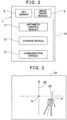
- the terminal device 7 will now be described with reference to FIG.2 .
- the terminal device 7 mainly includes a tilt sensor 8, an image pickup module 9, an arithmetic control module 11, a storage module 12, a communication module 13, and a display unit 14.
- the tilt sensor 8 can detect the tilts of the terminal device 7 in two axes (an X-axis, a Y-axis) to the horizontality, and the detection results are input to the arithmetic control module 11.
- One of the two axes of the tilt sensor 8 is parallel to an optical axis of the image pickup module 9. It is to be noted that the tilt sensor 8 may be configured to simply detect a tilt with respect to the verticality or the horizontality.
- a positional relationship and a distance between a reference position of the image pickup module 9, e.g., a center of an image pickup element (not shown) and the lower end of the pole 5 are also known.
- the image pickup module 9 can acquire a video image and a still image, and photographs an object which becomes a reference. For example, the image pickup module 9 photographs the total station 3 as a reference object.
- the image pickup module 9 has an image pickup element (not shown) for acquiring an image, and a CCD, a CMOS, or the like constituted of an aggregation of the pixels is used as the image pickup element.
- the image pickup element is orthogonal (vertical) to the optical axis of the image pickup module 9, the image pickup element has a coordinate system, a position of each pixel in the image pickup element is identified by the coordinate system, and a light receiving signal from each pixel includes the positional information in the image pickup element, the coordinate data of the coordinate system having as an origin a point at which the optical axis of the image pickup module 9 passes through the image pickup element.
- the coordinate axes orthogonal to each other in the coordinate system of the image pickup element are fixed to the pole 5, and have a know relationship to the axis of the pole 5.
- One of the coordinate axes is parallel or orthogonal to the axis of the pole 5.
- the image data output from the image pickup module 9 is constituted of light receiving signals output from the image pickup element.
- the image data is input to the arithmetic control module 11.
- the arithmetic control module 11 is typified by a CPU, and may be a CPU specialized for this instrument or a general-purpose CPU.
- the arithmetic control module 11 develops and executes the later-described programs and performs measuring, signal processing, calculating, controlling, and others.
- the communication module 13 can perform data communication of, e.g., image data or measurement data, and transmission/reception of data to/from the total station 3 may be enabled by the communication module 13.
- the storage module 12 may be a semiconductor memory incorporated in the terminal device 7 or a memory card attachable to/detachable from the terminal device 7, or it may be an externally attachable storage device.
- the programs include a display program configured to display the image data input from the image pickup module 9, the measurement data calculated by the arithmetic control module 11, or the like in the display unit 14, a program configured to identify the total station 3 based on an image acquired by the image pickup module 9 by the pattern recognition and calculate a position of the total station 3 in the image, a program configured to calculate a direction of the terminal device 7 with respect to the total station 3 based on the position of the total station 3 in the image, a program configured to divide a tilt angle with respect to the horizontality, which the tilt sensor 8 detects from a direction of the terminal device 7, into the tilt angles in two horizontal directions, a program configured to calculate movement amounts of the prism 6 (an optical center) in the two horizontal directions with respect to a measuring point P based on the tilt detection result from the tilt sensor 8 (or the tilt angles divided in the two horizontal directions) and the distance H, a program configured to correct a measurement result (the three-dimensional data) of the total station 3 about the prism 6 based on the movement amounts in the
- the total station 3 is installed on a reference point R. Since the total station 3 is subjected to the unmanned operation, the automatic operation or the remote-control operation is performed after installing the total station 3.
- the target instrument 2 is installed on the measuring point P.
- the installation of the target instrument 2 on the measuring point P is completed by matching the lower end of the ferrule with the measuring point P and directing the prism 6 or the terminal device 7 toward the total station 3.
- the operation of directing toward the total station 3 could be carried out as long as an image acquired by the image pickup module 9 is displayed in the display unit 14 and the total station 3 is included in the image.
- a straight line connecting the reference point R with the measuring point P is a y-axis
- a straight line which runs through the measuring point P and is orthogonal to the y-axis is an x-axis
- a straight line which runs through the measuring point P and is orthogonal (vertical) to the x-axis and the y-axis is a z-axis.
- the distance measuring light 16 from the total station 3 is projected toward the prism 6, and the three-dimensional measurement (the distance measurement, the measurement of the angles which are a horizontal angle and an elevation angle) of the prism 6 is performed. It is to be noted that the tracking light 17 is projected together with the distance measuring light 16, and the prism 6 is tracked. The tracking may be performed before installing the target instrument 2 or the tracking may be started simultaneously with the start of the measurement.
- the total station 3 transmits the measurement results to the target instrument 2 at the predetermined time intervals or in real time.
- a figure 3 ' of the total station 3 in the image is extracted by the pattern recognition or the like, and a position of the figure 3 ' in the image is calculated.
- a reference numeral 21 denotes an image displayed in the display unit 14, and a reference sign O designates a center of the image 21, i.e., a position of the optical axis of the image pickup module 9. Further, a position of the figure 3 ' in the image 21 corresponds to a position in an image element.
- the crossing alternate long and short dash lines 22 represent a coordinate system Q having the O as an origin.
- a reference numeral 23 denotes a vertical line running through the reference point R, and an intersection T on the vertical line 23 represents an optical axis of the total station 3.
- the intersection of the alternate long and short dash lines 22 coincides with the intersection T in the image 21. That is, when the terminal device 7 faces the total station 3 and the target instrument 2 is vertical, the intersection of the alternate long and short dash lines 22 coincides with the intersection T.
- the figure 3 ' appears on a lower side of the image 21. Further, when the target instrument 2 tilts leftward to the total station 3, the figure 3 ' appears on a right side of the image 21. That is, a position of the figure 3 ', which appears in the coordinate system Q (a position of the optical axis of the total station 3), indicates a tilt angle and a tilt direction of the target instrument 2.
- a up-and-down change in position of the figure 3 ' appears as a change in elevation angle ⁇ of the optical axis of the image pickup module 9 with respect to the horizontality, and hence a front-and-back tilt angle ⁇ of the target instrument 2 with respect to the verticality can be calculated based on the up-and-down change in position of the figure 3 '.
- a tilt angle of the target instrument 2 with respect to the verticality can be acquired in a state where the terminal device 7 faces the total station 3.
- the tilt angle ⁇ in the front-and-back direction and the tilt angle ⁇ in the right-and-left direction of the target instrument 2 can be also detected by the tilt sensor 8.
- the tilt sensor 8 detects the tilt angles in two axes orthogonal to each other, one axis is determined to be parallel to the optical axis of the image pickup module 9, and the other axis is determined as an axis which is orthogonal to the optical axis of the image pickup module 9 and extends in the horizontal direction.
- a position of the figure 3 ' changes.
- the figure 3 ' moves rightward in the image, and an amount of this movement corresponds to a horizontal rotation angle ⁇ of the optical axis of the image pickup module 9.
- the horizontal rotation angle ⁇ of the target instrument 2 that is, a change in direction of the target instrument 2 can be calculated.
- an actual tilt of the target instrument 2 includes a front-and-back or right-and-left tilt of the target instrument 2. Further, the actual tilt of the target instrument 2 includes the rotation of the target instrument 2 around the axis of the pole 5 (a deviation of a direction from the total station 3). Thus, a displacement which appears in the image includes the tilt of the target instrument 2 and a change in direction of the target instrument 2.
- the tilt sensor 8 detects the tilt angles in the two axial directions (an x-axis component, a y-axis component), and a synthetic tilt angle of the two axial directions represents a tilt angle ⁇ of the axis of the pole 5 with respect to the verticality.
- a direction of the tilt sensor 8 changes, and hence the x-axis component and the y-axis component change.
- the tilt angles (the x-axis component, the y-axis component) in the two axial directions detected by the tilt sensor 8 deviate from the x-axis component and the y-axis component in the x-axis direction and the y-axis direction in a measurement state.
- the synthetic tilt angle detected by the tilt sensor 8 is constant irrespective of a direction of the tilt sensor 8.
- the x-axis and the y-axis of the tilt sensor 8 are matched with the x-axis and the y-axis in the measurement state (the target instrument 2 is arranged to face the total station 3) and the x-axis component and the y-axis component detected by the tilt sensor 8 are corrected in such a manner that the synthetic angle becomes ⁇ , the actual x-axis component and y-axis component of the target instrument 2 in the measurement state can be detected.
- an x-axis and a y-axis correspond to the x-axis and the y-axis shown in FIG.1 . Further, it is assumed that an origin in the x-y coordinates in FIG.4 corresponds to the origin O in the image in FIG.3 , and each tilt angle shown in the x-y coordinates corresponds to the displacement in FIG.3 .
- a circle in FIG.4 represents a synthetic angle ⁇ obtained from the tilt angles of two axes detected by the tilt sensor 8.
- a tilt vector obtained from an x-axis component ⁇ x' and a y-axis component ⁇ y' detected by the tilt sensor 8 is represented by an arrow 25' in the drawing. Further, in the image 21, the figure 3 ' must appear at a position of a point of the arrow 25'.
- the arithmetic control module 11 calculates the deviation of the x-axis and the y-axis of the tilt sensor 8 based on the deviation amount ⁇ , and corrects the x-axis component ⁇ x' and the y-axis component ⁇ y' detected by the tilt sensor 8 to an x-axis component ⁇ x and a y-axis component ⁇ y of the x-axis and the y-axis in the measurement state based on the deviation amount. That is, the x-axis component ⁇ x' and the y-axis component ⁇ y' are corrected to tilt angles of the optical axis direction of the image pickup module 9 and a direction orthogonal to the optical axis.
- a tilt direction of the tilt sensor 8 shifts to a direction of the vector 25, and the values with which the synthetic angle of the x-axis component and the y-axis component becomes ⁇ in the direction of the vector 25, namely, ⁇ x (a tilt angle ⁇ x) and ⁇ y (a tilt angle ⁇ y) are acquired.
- the three-dimensional coordinates of the prism 6 are measured by the total station 3.
- a horizontal displacement amount (Hsin ⁇ ) of the prism 6 to the measuring point P is acquired based on the synthetic angle ⁇ and the distance H from the lower end of the target instrument 2 to the prism 6.
- a displacement ⁇ x of an x component with respect to the measuring point P can be acquired using (Hsin ⁇ ) ⁇ cos ⁇ x
- a displacement ⁇ y of a y component with respect to the measuring point P can be acquired using (Hsin ⁇ ) ⁇ cos ⁇ y.
- the measuring point P can be determined.
- the measuring point P can be accurately measured without accurately vertically supporting the target instrument 2 and without accurately arranging the target instrument 2 to face the total station 3.
- the measurement result of the total station 3 may be transmitted to the target instrument 2, or a tilt measurement result may be transmitted to the total station 3, and the calculation of the measuring point P may be performed by the target instrument 2 or the total station 3 in real time during the measurement.
- a measurement result of a tilt angle and a distance measurement result of the prism 6 may be stored by each measuring point respectively, and the calculation may be carried out by a PC or the like after the completion of all the measurements.
- a distance measurement result of the total station 3 is not required.
- the displacement amount of the prism 6 in the horizontal direction with reference to the measuring point P may be calculated by the arithmetic control module 11.
- the total station 3 is imaged as a reference object, and a position of the total station 3 in an image is detected by the pattern recognition.
- the guide light which is coaxial with the distance measuring light or parallel to the distance measuring light may be emitted from the total station 3, the guide light may be received by the image pickup module 9, the guide light may be determined as a reference object, and a position of the guide light may be detected.
- the distance measuring light or the tracking light may be used in place of the guide light.
- any measuring instrument having a tracking function can suffice, the measuring instrument is not restricted to the total station 3.
- the image pickup module 9 could be configured to enable detecting a tilt and a direction of the target instrument 2 from an acquired image. Therefore, the reference for detecting the tilt and the direction of the target instrument 2 does not have to be the total station 3, and something which can serve as the reference is installed at a predetermined position and if an object which can be the reference in a measuring direction is present, this object is used as the reference object.
- the target instrument 2 does not have to be vertically supported, it is possible to perform the measurement when the measuring point is a ceiling surface or a wall surface, or perform the measurement of a narrow part which a person cannot enter.
- the terminal device 7 can be connected to a wearable terminal as a display unit.
- a wearable terminal there is a head-up display or a glass type AR device, and using such a device enables improving the workability.
Landscapes
- Physics & Mathematics (AREA)
- Engineering & Computer Science (AREA)
- General Physics & Mathematics (AREA)
- Radar, Positioning & Navigation (AREA)
- Remote Sensing (AREA)
- Computer Networks & Wireless Communication (AREA)
- Electromagnetism (AREA)
- Optics & Photonics (AREA)
- Length Measuring Devices By Optical Means (AREA)
Claims (4)
- Ein Zielinstrument, umfassend: eine Stange (5), die an ihrem unteren Ende einen Hülsenteil aufweist, ein Prisma (6), das an der Stange vorgesehen und in einem bekannten Abstand von einem unteren Ende der Stange angeordnet ist, und ein an der Stange vorgesehenes Endgerät(7), wobei das Endgerät ein Bildaufnahmemodul (9) umfasst, das mit einer bekannten Stellung in Bezug auf die Stange befestigt ist, einen Neigungssensor (8), der Neigungen in zwei axialen Richtungen detektiert, die orthogonal zueinander sind und von denen eine axiale Richtung parallel zu einer optischen Achse des Bildaufnahmemoduls ist, und ein arithmetisches Steuermodul (11),wobei das Bildaufnahmemodul ein Bildaufnahmeelement aufweist und konfiguriert ist, ein Bild (21) aufzunehmen, das ein Referenzobjekt (3') als Referenz enthält, das an einer vorbestimmten Position in einer Messrichtung vorgesehen ist, wobei die optische Achse des Bildaufnahmemoduls (9) orthogonal zu einer Achse der Stange ist und orthogonal durch das Bildaufnahmeelement verläuft, das Bildaufnahmeelement ein Koordinatensystem aufweist, das einen Ursprungspunkt hat, an dem die optische Achse durch das Bildaufnahmeelement verläuft, eine Position jedes Pixels in dem Bildaufnahmeelement durch das Koordinatensystem identifiziert wird, ein Lichtempfangssignal von jedem Pixel die Positionsinformation in dem Bildaufnahmeelement enthält, eine der Koordinatenachsen des Koordinatensystems orthogonal oder parallel zu einer Achse der Stange ist,der Neigungssensor konfiguriert ist, Neigungswinkel in zwei zueinander orthogonalen Achsen des Zielinstruments (2) in Bezug auf die Vertikalität zu detektieren, und das arithmetische Steuermodul konfiguriert ist, eine Neigungsrichtung des Zielinstruments aus einer Position einer Abbildung des Referenzobjekts in dem Bild zu berechnen,eine Neigungsrichtung des Zielinstruments basierend auf Neigungswinkeln in den beiden axialen Richtungen des Neigungssensors zu berechnen,um eine Abweichung zwischen der aus dem Bild erfassten Neigungsrichtung des Zielinstruments und der Neigungsrichtung, die durch Berechnung der Neigungswinkel in den beiden axialen Richtungen erfasst wurde, basierend auf einem durch eine Drehung des Zielinstruments verursachten Abweichungswert zu erhalten,und die jeweiligen Neigungswinkel in den beiden axialen Richtungen des Neigungssensors in Neigungswinkel in Richtungen parallel zu der optischen Achse des Bildaufnahmemoduls und orthogonal zu der optischen Achse basierend auf der Abweichung in einem Zustand zu korrigieren, in dem das Endgerät (7) dem Referenzobjekt zugewandt ist.
- Zielinstrument nach Anspruch 1, wobei das arithmetische Steuermodul (11) konfiguriert ist, eine Verschiebung des Prismas (6) in einer horizontalen Richtung in Bezug auf eine untere Endposition basierend auf den korrigierten Neigungswinkeln und dem Abstand von dem unteren Ende der Stange (5) zu berechnen.
- Zielinstrument nach einem der Ansprüche 1-2, wobei das Endgerät (7) ein Smartphone ist.
- Vermessungssystem umfassend das Zielinstrument (2) nach einem der Ansprüche 1 bis 3 und ein Vermessungsinstrument (3) mit einer Tracking-Funktion, wobei das Vermessungssystem konfiguriert ist, ein unteres Ende des Zielinstruments basierend auf einem Messergebnis des Prismas (6) durch das Vermessungsinstrument, Neigungswinkeln des Zielinstruments und einem Abstand von dem unteren Ende der Stange (5) zum Prisma zu messen.
Applications Claiming Priority (1)
| Application Number | Priority Date | Filing Date | Title |
|---|---|---|---|
| JP2019033208A JP7287793B2 (ja) | 2019-02-26 | 2019-02-26 | ターゲット装置及び測量システム |
Publications (2)
| Publication Number | Publication Date |
|---|---|
| EP3702728A1 EP3702728A1 (de) | 2020-09-02 |
| EP3702728B1 true EP3702728B1 (de) | 2025-05-07 |
Family
ID=69845802
Family Applications (1)
| Application Number | Title | Priority Date | Filing Date |
|---|---|---|---|
| EP20159052.8A Active EP3702728B1 (de) | 2019-02-26 | 2020-02-24 | Zielinstrument und vermessungssystem |
Country Status (3)
| Country | Link |
|---|---|
| US (1) | US11550034B2 (de) |
| EP (1) | EP3702728B1 (de) |
| JP (1) | JP7287793B2 (de) |
Families Citing this family (8)
| Publication number | Priority date | Publication date | Assignee | Title |
|---|---|---|---|---|
| JP7488737B2 (ja) * | 2020-09-18 | 2024-05-22 | 株式会社トプコン | 制御システム、測量装置をターゲットの方向に指向させる方法およびプログラム |
| JP2022140903A (ja) * | 2021-03-15 | 2022-09-29 | 株式会社トプコン | 測量デバイスおよびこれを用いた測量方法 |
| JP2023050332A (ja) * | 2021-09-30 | 2023-04-11 | 株式会社トプコン | 測量システム |
| CN115127483B (zh) * | 2022-07-05 | 2025-12-19 | 深圳市中图仪器股份有限公司 | 用于测量同轴度的检测方法、以及检测同轴度的系统 |
| CN114882028B (zh) * | 2022-07-08 | 2022-10-21 | 深圳市瑞祥鑫五金制品有限公司 | 一种基于多摄像头的焊接端子检测方法、装置及系统 |
| CN115900755B (zh) * | 2022-08-30 | 2024-04-02 | 中国科学院上海天文台 | 一种靶标指向自动修正方法及实现该方法的靶标 |
| JP2024145599A (ja) * | 2023-03-31 | 2024-10-15 | 株式会社トプコン | 測量システム、測量装置、測量方法及び測量プログラム |
| JP2024151268A (ja) * | 2023-04-11 | 2024-10-24 | 株式会社トプコン | 測量システム及び測定方法 |
Family Cites Families (10)
| Publication number | Priority date | Publication date | Assignee | Title |
|---|---|---|---|---|
| JP2001241950A (ja) | 2000-03-02 | 2001-09-07 | Topcon Corp | ターゲット、測量装置及び測量方法 |
| US9134127B2 (en) * | 2011-06-24 | 2015-09-15 | Trimble Navigation Limited | Determining tilt angle and tilt direction using image processing |
| JP6253932B2 (ja) | 2013-09-17 | 2017-12-27 | 株式会社トプコン | 方向検出装置及び測量システム |
| JP2016045002A (ja) | 2014-08-20 | 2016-04-04 | 株式会社トプコン | 照度測定システム |
| JP6418889B2 (ja) * | 2014-10-20 | 2018-11-07 | 株式会社トプコン | 測量システムおよびこの測量システムに用いる携帯型無線送受信装置ならびに測量用ポール。 |
| JP6630515B2 (ja) * | 2015-08-25 | 2020-01-15 | 株式会社トプコン | 位置誘導装置、位置誘導方法、プログラム |
| JP6713847B2 (ja) * | 2016-06-14 | 2020-06-24 | 株式会社トプコン | 測量システム |
| JP6937126B2 (ja) | 2017-01-31 | 2021-09-22 | 株式会社トプコン | ローバー及びローバー測定システム |
| JP7240137B2 (ja) * | 2018-11-07 | 2023-03-15 | 株式会社トプコン | ターゲット装置及び測定システム |
| JP7183017B2 (ja) * | 2018-12-11 | 2022-12-05 | 株式会社トプコン | 測量装置及び写真測量方法 |
-
2019
- 2019-02-26 JP JP2019033208A patent/JP7287793B2/ja active Active
-
2020
- 2020-02-24 EP EP20159052.8A patent/EP3702728B1/de active Active
- 2020-02-25 US US16/799,967 patent/US11550034B2/en active Active
Also Published As
| Publication number | Publication date |
|---|---|
| US20200271758A1 (en) | 2020-08-27 |
| JP2020139750A (ja) | 2020-09-03 |
| JP7287793B2 (ja) | 2023-06-06 |
| US11550034B2 (en) | 2023-01-10 |
| EP3702728A1 (de) | 2020-09-02 |
Similar Documents
| Publication | Publication Date | Title |
|---|---|---|
| EP3702728B1 (de) | Zielinstrument und vermessungssystem | |
| US10469754B2 (en) | Position guiding device, position guiding method, and position guiding program | |
| EP3483554B1 (de) | Kalibrierungsprüfverfahren für vermessungsgerät | |
| US10634795B2 (en) | Rover and rover measuring system | |
| EP2788715B1 (de) | Robotisches nivellierungsinstrument | |
| JP6864653B2 (ja) | 鉛直測定システム及び基準点のトレース方法 | |
| US20010019101A1 (en) | Target, surveying systems and surveying method | |
| EP3751231B1 (de) | Vermessungsinstrument | |
| US11421989B2 (en) | Surveying instrument | |
| US12013239B2 (en) | Marking system and marking method | |
| US12359915B2 (en) | Surveying instrument and surveying system | |
| US6611664B2 (en) | Stereo image photographing system | |
| JP2021039013A (ja) | 壁面のひび割れ測定機および測定方法 | |
| CN111308485B (zh) | 测量装置和照相测量方法 | |
| US12535319B2 (en) | Surveying apparatus, surveying method, and surveying program | |
| KR101103354B1 (ko) | 자동제어기능을 갖는 측량장치 | |
| JP5793777B2 (ja) | 鉛直指示機 | |
| JP5789868B2 (ja) | 水平位置案内機 | |
| US20250216198A1 (en) | Rover orientation measurement for surveying tilt orientation | |
| JP2025186766A (ja) | 測量システム及び測量方法 | |
| JP2018048922A (ja) | 測量装置及び測量方法 |
Legal Events
| Date | Code | Title | Description |
|---|---|---|---|
| PUAI | Public reference made under article 153(3) epc to a published international application that has entered the european phase |
Free format text: ORIGINAL CODE: 0009012 |
|
| STAA | Information on the status of an ep patent application or granted ep patent |
Free format text: STATUS: REQUEST FOR EXAMINATION WAS MADE |
|
| 17P | Request for examination filed |
Effective date: 20200224 |
|
| AK | Designated contracting states |
Kind code of ref document: A1 Designated state(s): AL AT BE BG CH CY CZ DE DK EE ES FI FR GB GR HR HU IE IS IT LI LT LU LV MC MK MT NL NO PL PT RO RS SE SI SK SM TR |
|
| AX | Request for extension of the european patent |
Extension state: BA ME |
|
| RBV | Designated contracting states (corrected) |
Designated state(s): AL AT BE BG CH CY CZ DE DK EE ES FI FR GB GR HR HU IE IS IT LI LT LU LV MC MK MT NL NO PL PT RO RS SE SI SK SM TR |
|
| STAA | Information on the status of an ep patent application or granted ep patent |
Free format text: STATUS: EXAMINATION IS IN PROGRESS |
|
| 17Q | First examination report despatched |
Effective date: 20210831 |
|
| GRAP | Despatch of communication of intention to grant a patent |
Free format text: ORIGINAL CODE: EPIDOSNIGR1 |
|
| STAA | Information on the status of an ep patent application or granted ep patent |
Free format text: STATUS: GRANT OF PATENT IS INTENDED |
|
| INTG | Intention to grant announced |
Effective date: 20241219 |
|
| GRAS | Grant fee paid |
Free format text: ORIGINAL CODE: EPIDOSNIGR3 |
|
| GRAA | (expected) grant |
Free format text: ORIGINAL CODE: 0009210 |
|
| STAA | Information on the status of an ep patent application or granted ep patent |
Free format text: STATUS: THE PATENT HAS BEEN GRANTED |
|
| AK | Designated contracting states |
Kind code of ref document: B1 Designated state(s): AL AT BE BG CH CY CZ DE DK EE ES FI FR GB GR HR HU IE IS IT LI LT LU LV MC MK MT NL NO PL PT RO RS SE SI SK SM TR |
|
| REG | Reference to a national code |
Ref country code: GB Ref legal event code: FG4D |
|
| REG | Reference to a national code |
Ref country code: CH Ref legal event code: EP |
|
| REG | Reference to a national code |
Ref country code: DE Ref legal event code: R096 Ref document number: 602020050697 Country of ref document: DE |
|
| REG | Reference to a national code |
Ref country code: IE Ref legal event code: FG4D |
|
| REG | Reference to a national code |
Ref country code: NL Ref legal event code: MP Effective date: 20250507 |
|
| PG25 | Lapsed in a contracting state [announced via postgrant information from national office to epo] |
Ref country code: PT Free format text: LAPSE BECAUSE OF FAILURE TO SUBMIT A TRANSLATION OF THE DESCRIPTION OR TO PAY THE FEE WITHIN THE PRESCRIBED TIME-LIMIT Effective date: 20250908 Ref country code: ES Free format text: LAPSE BECAUSE OF FAILURE TO SUBMIT A TRANSLATION OF THE DESCRIPTION OR TO PAY THE FEE WITHIN THE PRESCRIBED TIME-LIMIT Effective date: 20250507 Ref country code: FI Free format text: LAPSE BECAUSE OF FAILURE TO SUBMIT A TRANSLATION OF THE DESCRIPTION OR TO PAY THE FEE WITHIN THE PRESCRIBED TIME-LIMIT Effective date: 20250507 |
|
| REG | Reference to a national code |
Ref country code: LT Ref legal event code: MG9D |
|
| PG25 | Lapsed in a contracting state [announced via postgrant information from national office to epo] |
Ref country code: NO Free format text: LAPSE BECAUSE OF FAILURE TO SUBMIT A TRANSLATION OF THE DESCRIPTION OR TO PAY THE FEE WITHIN THE PRESCRIBED TIME-LIMIT Effective date: 20250807 Ref country code: GR Free format text: LAPSE BECAUSE OF FAILURE TO SUBMIT A TRANSLATION OF THE DESCRIPTION OR TO PAY THE FEE WITHIN THE PRESCRIBED TIME-LIMIT Effective date: 20250808 |
|
| PG25 | Lapsed in a contracting state [announced via postgrant information from national office to epo] |
Ref country code: NL Free format text: LAPSE BECAUSE OF FAILURE TO SUBMIT A TRANSLATION OF THE DESCRIPTION OR TO PAY THE FEE WITHIN THE PRESCRIBED TIME-LIMIT Effective date: 20250507 Ref country code: PL Free format text: LAPSE BECAUSE OF FAILURE TO SUBMIT A TRANSLATION OF THE DESCRIPTION OR TO PAY THE FEE WITHIN THE PRESCRIBED TIME-LIMIT Effective date: 20250507 |
|
| REG | Reference to a national code |
Ref country code: AT Ref legal event code: MK05 Ref document number: 1792890 Country of ref document: AT Kind code of ref document: T Effective date: 20250507 |
|
| PG25 | Lapsed in a contracting state [announced via postgrant information from national office to epo] |
Ref country code: BG Free format text: LAPSE BECAUSE OF FAILURE TO SUBMIT A TRANSLATION OF THE DESCRIPTION OR TO PAY THE FEE WITHIN THE PRESCRIBED TIME-LIMIT Effective date: 20250507 |
|
| PG25 | Lapsed in a contracting state [announced via postgrant information from national office to epo] |
Ref country code: HR Free format text: LAPSE BECAUSE OF FAILURE TO SUBMIT A TRANSLATION OF THE DESCRIPTION OR TO PAY THE FEE WITHIN THE PRESCRIBED TIME-LIMIT Effective date: 20250507 |
|
| PG25 | Lapsed in a contracting state [announced via postgrant information from national office to epo] |
Ref country code: AT Free format text: LAPSE BECAUSE OF FAILURE TO SUBMIT A TRANSLATION OF THE DESCRIPTION OR TO PAY THE FEE WITHIN THE PRESCRIBED TIME-LIMIT Effective date: 20250507 |
|
| PG25 | Lapsed in a contracting state [announced via postgrant information from national office to epo] |
Ref country code: RS Free format text: LAPSE BECAUSE OF FAILURE TO SUBMIT A TRANSLATION OF THE DESCRIPTION OR TO PAY THE FEE WITHIN THE PRESCRIBED TIME-LIMIT Effective date: 20250807 |
|
| PG25 | Lapsed in a contracting state [announced via postgrant information from national office to epo] |
Ref country code: IS Free format text: LAPSE BECAUSE OF FAILURE TO SUBMIT A TRANSLATION OF THE DESCRIPTION OR TO PAY THE FEE WITHIN THE PRESCRIBED TIME-LIMIT Effective date: 20250907 |
|
| PG25 | Lapsed in a contracting state [announced via postgrant information from national office to epo] |
Ref country code: LV Free format text: LAPSE BECAUSE OF FAILURE TO SUBMIT A TRANSLATION OF THE DESCRIPTION OR TO PAY THE FEE WITHIN THE PRESCRIBED TIME-LIMIT Effective date: 20250507 |
|
| PG25 | Lapsed in a contracting state [announced via postgrant information from national office to epo] |
Ref country code: DK Free format text: LAPSE BECAUSE OF FAILURE TO SUBMIT A TRANSLATION OF THE DESCRIPTION OR TO PAY THE FEE WITHIN THE PRESCRIBED TIME-LIMIT Effective date: 20250507 Ref country code: SM Free format text: LAPSE BECAUSE OF FAILURE TO SUBMIT A TRANSLATION OF THE DESCRIPTION OR TO PAY THE FEE WITHIN THE PRESCRIBED TIME-LIMIT Effective date: 20250507 |
|
| PG25 | Lapsed in a contracting state [announced via postgrant information from national office to epo] |
Ref country code: CZ Free format text: LAPSE BECAUSE OF FAILURE TO SUBMIT A TRANSLATION OF THE DESCRIPTION OR TO PAY THE FEE WITHIN THE PRESCRIBED TIME-LIMIT Effective date: 20250507 |
|
| PG25 | Lapsed in a contracting state [announced via postgrant information from national office to epo] |
Ref country code: EE Free format text: LAPSE BECAUSE OF FAILURE TO SUBMIT A TRANSLATION OF THE DESCRIPTION OR TO PAY THE FEE WITHIN THE PRESCRIBED TIME-LIMIT Effective date: 20250507 |
|
| PG25 | Lapsed in a contracting state [announced via postgrant information from national office to epo] |
Ref country code: SK Free format text: LAPSE BECAUSE OF FAILURE TO SUBMIT A TRANSLATION OF THE DESCRIPTION OR TO PAY THE FEE WITHIN THE PRESCRIBED TIME-LIMIT Effective date: 20250507 Ref country code: RO Free format text: LAPSE BECAUSE OF FAILURE TO SUBMIT A TRANSLATION OF THE DESCRIPTION OR TO PAY THE FEE WITHIN THE PRESCRIBED TIME-LIMIT Effective date: 20250507 |
|
| PG25 | Lapsed in a contracting state [announced via postgrant information from national office to epo] |
Ref country code: IT Free format text: LAPSE BECAUSE OF FAILURE TO SUBMIT A TRANSLATION OF THE DESCRIPTION OR TO PAY THE FEE WITHIN THE PRESCRIBED TIME-LIMIT Effective date: 20250507 |
|
| REG | Reference to a national code |
Ref country code: DE Ref legal event code: R097 Ref document number: 602020050697 Country of ref document: DE |
|
| REG | Reference to a national code |
Ref country code: CH Ref legal event code: U11 Free format text: ST27 STATUS EVENT CODE: U-0-0-U10-U11 (AS PROVIDED BY THE NATIONAL OFFICE) Effective date: 20260301 |
|
| PLBE | No opposition filed within time limit |
Free format text: ORIGINAL CODE: 0009261 |
|
| STAA | Information on the status of an ep patent application or granted ep patent |
Free format text: STATUS: NO OPPOSITION FILED WITHIN TIME LIMIT |
|
| REG | Reference to a national code |
Ref country code: CH Ref legal event code: L10 Free format text: ST27 STATUS EVENT CODE: U-0-0-L10-L00 (AS PROVIDED BY THE NATIONAL OFFICE) Effective date: 20260318 |
|
| PGFP | Annual fee paid to national office [announced via postgrant information from national office to epo] |
Ref country code: DE Payment date: 20260102 Year of fee payment: 7 |
|
| 26N | No opposition filed |
Effective date: 20260210 |