EP3702121A1 - Procédé de production d'un objet moulé en céramique - Google Patents
Procédé de production d'un objet moulé en céramique Download PDFInfo
- Publication number
- EP3702121A1 EP3702121A1 EP18870824.2A EP18870824A EP3702121A1 EP 3702121 A1 EP3702121 A1 EP 3702121A1 EP 18870824 A EP18870824 A EP 18870824A EP 3702121 A1 EP3702121 A1 EP 3702121A1
- Authority
- EP
- European Patent Office
- Prior art keywords
- powder
- manufactured object
- laser beam
- laser
- producing
- Prior art date
- Legal status (The legal status is an assumption and is not a legal conclusion. Google has not performed a legal analysis and makes no representation as to the accuracy of the status listed.)
- Granted
Links
- 239000000919 ceramic Substances 0.000 title claims abstract description 27
- 238000004519 manufacturing process Methods 0.000 title abstract description 28
- 239000000843 powder Substances 0.000 claims abstract description 122
- 230000001678 irradiating effect Effects 0.000 claims abstract description 14
- 238000000034 method Methods 0.000 claims description 37
- 230000004927 fusion Effects 0.000 claims description 19
- 238000010438 heat treatment Methods 0.000 claims description 11
- 229910052751 metal Inorganic materials 0.000 claims description 8
- 239000002184 metal Substances 0.000 claims description 8
- 229910044991 metal oxide Inorganic materials 0.000 claims description 7
- 150000004706 metal oxides Chemical class 0.000 claims description 7
- 239000000835 fiber Substances 0.000 claims description 5
- 230000004580 weight loss Effects 0.000 claims description 5
- 229910052782 aluminium Inorganic materials 0.000 claims description 2
- XAGFODPZIPBFFR-UHFFFAOYSA-N aluminium Chemical group [Al] XAGFODPZIPBFFR-UHFFFAOYSA-N 0.000 claims description 2
- 238000009499 grossing Methods 0.000 abstract 1
- 230000000052 comparative effect Effects 0.000 description 18
- 239000000126 substance Substances 0.000 description 16
- 238000007711 solidification Methods 0.000 description 10
- 230000008023 solidification Effects 0.000 description 10
- CMIHHWBVHJVIGI-UHFFFAOYSA-N gadolinium(iii) oxide Chemical compound [O-2].[O-2].[O-2].[Gd+3].[Gd+3] CMIHHWBVHJVIGI-UHFFFAOYSA-N 0.000 description 9
- 238000001816 cooling Methods 0.000 description 7
- 238000002425 crystallisation Methods 0.000 description 7
- 230000008025 crystallization Effects 0.000 description 7
- 239000000463 material Substances 0.000 description 7
- 230000003287 optical effect Effects 0.000 description 7
- 238000007500 overflow downdraw method Methods 0.000 description 7
- 238000009826 distribution Methods 0.000 description 6
- 230000015572 biosynthetic process Effects 0.000 description 5
- 238000001887 electron backscatter diffraction Methods 0.000 description 5
- 229910001938 gadolinium oxide Inorganic materials 0.000 description 5
- 229940075613 gadolinium oxide Drugs 0.000 description 5
- PNEYBMLMFCGWSK-UHFFFAOYSA-N aluminium oxide Inorganic materials [O-2].[O-2].[O-2].[Al+3].[Al+3] PNEYBMLMFCGWSK-UHFFFAOYSA-N 0.000 description 4
- 229910010293 ceramic material Inorganic materials 0.000 description 4
- 230000008018 melting Effects 0.000 description 4
- 238000002844 melting Methods 0.000 description 4
- TWNQGVIAIRXVLR-UHFFFAOYSA-N oxo(oxoalumanyloxy)alumane Chemical compound O=[Al]O[Al]=O TWNQGVIAIRXVLR-UHFFFAOYSA-N 0.000 description 4
- 230000008859 change Effects 0.000 description 3
- 230000005496 eutectics Effects 0.000 description 3
- 238000011156 evaluation Methods 0.000 description 3
- 239000002245 particle Substances 0.000 description 3
- 229910003447 praseodymium oxide Inorganic materials 0.000 description 3
- 229910003451 terbium oxide Inorganic materials 0.000 description 3
- CURLTUGMZLYLDI-UHFFFAOYSA-N Carbon dioxide Chemical compound O=C=O CURLTUGMZLYLDI-UHFFFAOYSA-N 0.000 description 2
- 229910002637 Pr6O11 Inorganic materials 0.000 description 2
- 238000010521 absorption reaction Methods 0.000 description 2
- 230000007423 decrease Effects 0.000 description 2
- 230000003247 decreasing effect Effects 0.000 description 2
- 238000009792 diffusion process Methods 0.000 description 2
- 230000000694 effects Effects 0.000 description 2
- 238000010894 electron beam technology Methods 0.000 description 2
- 238000005516 engineering process Methods 0.000 description 2
- 238000011835 investigation Methods 0.000 description 2
- 238000012423 maintenance Methods 0.000 description 2
- 150000002739 metals Chemical class 0.000 description 2
- 239000011812 mixed powder Substances 0.000 description 2
- 239000000203 mixture Substances 0.000 description 2
- MMKQUGHLEMYQSG-UHFFFAOYSA-N oxygen(2-);praseodymium(3+) Chemical compound [O-2].[O-2].[O-2].[Pr+3].[Pr+3] MMKQUGHLEMYQSG-UHFFFAOYSA-N 0.000 description 2
- NRNCYVBFPDDJNE-UHFFFAOYSA-N pemoline Chemical compound O1C(N)=NC(=O)C1C1=CC=CC=C1 NRNCYVBFPDDJNE-UHFFFAOYSA-N 0.000 description 2
- 238000005245 sintering Methods 0.000 description 2
- 229910016341 Al2O3 ZrO2 Inorganic materials 0.000 description 1
- OKTJSMMVPCPJKN-UHFFFAOYSA-N Carbon Chemical compound [C] OKTJSMMVPCPJKN-UHFFFAOYSA-N 0.000 description 1
- HEQHIXXLFUMNDC-UHFFFAOYSA-N O.O.O.O.O.O.O.[Tb].[Tb].[Tb].[Tb] Chemical compound O.O.O.O.O.O.O.[Tb].[Tb].[Tb].[Tb] HEQHIXXLFUMNDC-UHFFFAOYSA-N 0.000 description 1
- 229910052777 Praseodymium Inorganic materials 0.000 description 1
- 229910052771 Terbium Inorganic materials 0.000 description 1
- 230000008901 benefit Effects 0.000 description 1
- 239000011230 binding agent Substances 0.000 description 1
- 229910052799 carbon Inorganic materials 0.000 description 1
- 229910002092 carbon dioxide Inorganic materials 0.000 description 1
- 239000001569 carbon dioxide Substances 0.000 description 1
- 229910052593 corundum Inorganic materials 0.000 description 1
- 229910002106 crystalline ceramic Inorganic materials 0.000 description 1
- 239000011222 crystalline ceramic Substances 0.000 description 1
- 238000000354 decomposition reaction Methods 0.000 description 1
- 238000011161 development Methods 0.000 description 1
- 238000002309 gasification Methods 0.000 description 1
- 239000011521 glass Substances 0.000 description 1
- 230000006872 improvement Effects 0.000 description 1
- 238000012986 modification Methods 0.000 description 1
- 230000004048 modification Effects 0.000 description 1
- RVTZCBVAJQQJTK-UHFFFAOYSA-N oxygen(2-);zirconium(4+) Chemical compound [O-2].[O-2].[Zr+4] RVTZCBVAJQQJTK-UHFFFAOYSA-N 0.000 description 1
- 230000002093 peripheral effect Effects 0.000 description 1
- 238000005498 polishing Methods 0.000 description 1
- PUDIUYLPXJFUGB-UHFFFAOYSA-N praseodymium atom Chemical compound [Pr] PUDIUYLPXJFUGB-UHFFFAOYSA-N 0.000 description 1
- 238000002360 preparation method Methods 0.000 description 1
- 239000000047 product Substances 0.000 description 1
- 229910052761 rare earth metal Inorganic materials 0.000 description 1
- 239000002994 raw material Substances 0.000 description 1
- 239000011347 resin Substances 0.000 description 1
- 229920005989 resin Polymers 0.000 description 1
- 230000000717 retained effect Effects 0.000 description 1
- 229910052594 sapphire Inorganic materials 0.000 description 1
- 238000000926 separation method Methods 0.000 description 1
- 238000007493 shaping process Methods 0.000 description 1
- 239000012798 spherical particle Substances 0.000 description 1
- 238000003892 spreading Methods 0.000 description 1
- 230000007480 spreading Effects 0.000 description 1
- 239000013589 supplement Substances 0.000 description 1
- GZCRRIHWUXGPOV-UHFFFAOYSA-N terbium atom Chemical compound [Tb] GZCRRIHWUXGPOV-UHFFFAOYSA-N 0.000 description 1
- SCRZPWWVSXWCMC-UHFFFAOYSA-N terbium(iii) oxide Chemical compound [O-2].[O-2].[O-2].[Tb+3].[Tb+3] SCRZPWWVSXWCMC-UHFFFAOYSA-N 0.000 description 1
- 230000008646 thermal stress Effects 0.000 description 1
- 238000012795 verification Methods 0.000 description 1
- XLYOFNOQVPJJNP-UHFFFAOYSA-N water Substances O XLYOFNOQVPJJNP-UHFFFAOYSA-N 0.000 description 1
- 229910001845 yogo sapphire Inorganic materials 0.000 description 1
- 229910001928 zirconium oxide Inorganic materials 0.000 description 1
Images


Classifications
-
- B—PERFORMING OPERATIONS; TRANSPORTING
- B28—WORKING CEMENT, CLAY, OR STONE
- B28B—SHAPING CLAY OR OTHER CERAMIC COMPOSITIONS; SHAPING SLAG; SHAPING MIXTURES CONTAINING CEMENTITIOUS MATERIAL, e.g. PLASTER
- B28B1/00—Producing shaped prefabricated articles from the material
- B28B1/001—Rapid manufacturing of 3D objects by additive depositing, agglomerating or laminating of material
-
- B—PERFORMING OPERATIONS; TRANSPORTING
- B29—WORKING OF PLASTICS; WORKING OF SUBSTANCES IN A PLASTIC STATE IN GENERAL
- B29C—SHAPING OR JOINING OF PLASTICS; SHAPING OF MATERIAL IN A PLASTIC STATE, NOT OTHERWISE PROVIDED FOR; AFTER-TREATMENT OF THE SHAPED PRODUCTS, e.g. REPAIRING
- B29C64/00—Additive manufacturing, i.e. manufacturing of three-dimensional [3D] objects by additive deposition, additive agglomeration or additive layering, e.g. by 3D printing, stereolithography or selective laser sintering
- B29C64/10—Processes of additive manufacturing
- B29C64/141—Processes of additive manufacturing using only solid materials
- B29C64/153—Processes of additive manufacturing using only solid materials using layers of powder being selectively joined, e.g. by selective laser sintering or melting
-
- B—PERFORMING OPERATIONS; TRANSPORTING
- B29—WORKING OF PLASTICS; WORKING OF SUBSTANCES IN A PLASTIC STATE IN GENERAL
- B29C—SHAPING OR JOINING OF PLASTICS; SHAPING OF MATERIAL IN A PLASTIC STATE, NOT OTHERWISE PROVIDED FOR; AFTER-TREATMENT OF THE SHAPED PRODUCTS, e.g. REPAIRING
- B29C64/00—Additive manufacturing, i.e. manufacturing of three-dimensional [3D] objects by additive deposition, additive agglomeration or additive layering, e.g. by 3D printing, stereolithography or selective laser sintering
- B29C64/20—Apparatus for additive manufacturing; Details thereof or accessories therefor
- B29C64/264—Arrangements for irradiation
- B29C64/268—Arrangements for irradiation using laser beams; using electron beams [EB]
-
- B—PERFORMING OPERATIONS; TRANSPORTING
- B29—WORKING OF PLASTICS; WORKING OF SUBSTANCES IN A PLASTIC STATE IN GENERAL
- B29C—SHAPING OR JOINING OF PLASTICS; SHAPING OF MATERIAL IN A PLASTIC STATE, NOT OTHERWISE PROVIDED FOR; AFTER-TREATMENT OF THE SHAPED PRODUCTS, e.g. REPAIRING
- B29C64/00—Additive manufacturing, i.e. manufacturing of three-dimensional [3D] objects by additive deposition, additive agglomeration or additive layering, e.g. by 3D printing, stereolithography or selective laser sintering
- B29C64/30—Auxiliary operations or equipment
- B29C64/386—Data acquisition or data processing for additive manufacturing
- B29C64/393—Data acquisition or data processing for additive manufacturing for controlling or regulating additive manufacturing processes
-
- B—PERFORMING OPERATIONS; TRANSPORTING
- B33—ADDITIVE MANUFACTURING TECHNOLOGY
- B33Y—ADDITIVE MANUFACTURING, i.e. MANUFACTURING OF THREE-DIMENSIONAL [3-D] OBJECTS BY ADDITIVE DEPOSITION, ADDITIVE AGGLOMERATION OR ADDITIVE LAYERING, e.g. BY 3-D PRINTING, STEREOLITHOGRAPHY OR SELECTIVE LASER SINTERING
- B33Y10/00—Processes of additive manufacturing
-
- B—PERFORMING OPERATIONS; TRANSPORTING
- B33—ADDITIVE MANUFACTURING TECHNOLOGY
- B33Y—ADDITIVE MANUFACTURING, i.e. MANUFACTURING OF THREE-DIMENSIONAL [3-D] OBJECTS BY ADDITIVE DEPOSITION, ADDITIVE AGGLOMERATION OR ADDITIVE LAYERING, e.g. BY 3-D PRINTING, STEREOLITHOGRAPHY OR SELECTIVE LASER SINTERING
- B33Y30/00—Apparatus for additive manufacturing; Details thereof or accessories therefor
-
- B—PERFORMING OPERATIONS; TRANSPORTING
- B33—ADDITIVE MANUFACTURING TECHNOLOGY
- B33Y—ADDITIVE MANUFACTURING, i.e. MANUFACTURING OF THREE-DIMENSIONAL [3-D] OBJECTS BY ADDITIVE DEPOSITION, ADDITIVE AGGLOMERATION OR ADDITIVE LAYERING, e.g. BY 3-D PRINTING, STEREOLITHOGRAPHY OR SELECTIVE LASER SINTERING
- B33Y50/00—Data acquisition or data processing for additive manufacturing
- B33Y50/02—Data acquisition or data processing for additive manufacturing for controlling or regulating additive manufacturing processes
-
- B—PERFORMING OPERATIONS; TRANSPORTING
- B33—ADDITIVE MANUFACTURING TECHNOLOGY
- B33Y—ADDITIVE MANUFACTURING, i.e. MANUFACTURING OF THREE-DIMENSIONAL [3-D] OBJECTS BY ADDITIVE DEPOSITION, ADDITIVE AGGLOMERATION OR ADDITIVE LAYERING, e.g. BY 3-D PRINTING, STEREOLITHOGRAPHY OR SELECTIVE LASER SINTERING
- B33Y70/00—Materials specially adapted for additive manufacturing
- B33Y70/10—Composites of different types of material, e.g. mixtures of ceramics and polymers or mixtures of metals and biomaterials
-
- B—PERFORMING OPERATIONS; TRANSPORTING
- B33—ADDITIVE MANUFACTURING TECHNOLOGY
- B33Y—ADDITIVE MANUFACTURING, i.e. MANUFACTURING OF THREE-DIMENSIONAL [3-D] OBJECTS BY ADDITIVE DEPOSITION, ADDITIVE AGGLOMERATION OR ADDITIVE LAYERING, e.g. BY 3-D PRINTING, STEREOLITHOGRAPHY OR SELECTIVE LASER SINTERING
- B33Y80/00—Products made by additive manufacturing
-
- C—CHEMISTRY; METALLURGY
- C03—GLASS; MINERAL OR SLAG WOOL
- C03B—MANUFACTURE, SHAPING, OR SUPPLEMENTARY PROCESSES
- C03B19/00—Other methods of shaping glass
-
- C—CHEMISTRY; METALLURGY
- C03—GLASS; MINERAL OR SLAG WOOL
- C03C—CHEMICAL COMPOSITION OF GLASSES, GLAZES OR VITREOUS ENAMELS; SURFACE TREATMENT OF GLASS; SURFACE TREATMENT OF FIBRES OR FILAMENTS MADE FROM GLASS, MINERALS OR SLAGS; JOINING GLASS TO GLASS OR OTHER MATERIALS
- C03C10/00—Devitrified glass ceramics, i.e. glass ceramics having a crystalline phase dispersed in a glassy phase and constituting at least 50% by weight of the total composition
-
- C—CHEMISTRY; METALLURGY
- C03—GLASS; MINERAL OR SLAG WOOL
- C03C—CHEMICAL COMPOSITION OF GLASSES, GLAZES OR VITREOUS ENAMELS; SURFACE TREATMENT OF GLASS; SURFACE TREATMENT OF FIBRES OR FILAMENTS MADE FROM GLASS, MINERALS OR SLAGS; JOINING GLASS TO GLASS OR OTHER MATERIALS
- C03C3/00—Glass compositions
- C03C3/12—Silica-free oxide glass compositions
- C03C3/125—Silica-free oxide glass compositions containing aluminium as glass former
-
- C—CHEMISTRY; METALLURGY
- C04—CEMENTS; CONCRETE; ARTIFICIAL STONE; CERAMICS; REFRACTORIES
- C04B—LIME, MAGNESIA; SLAG; CEMENTS; COMPOSITIONS THEREOF, e.g. MORTARS, CONCRETE OR LIKE BUILDING MATERIALS; ARTIFICIAL STONE; CERAMICS; REFRACTORIES; TREATMENT OF NATURAL STONE
- C04B35/00—Shaped ceramic products characterised by their composition; Ceramics compositions; Processing powders of inorganic compounds preparatory to the manufacturing of ceramic products
- C04B35/01—Shaped ceramic products characterised by their composition; Ceramics compositions; Processing powders of inorganic compounds preparatory to the manufacturing of ceramic products based on oxide ceramics
- C04B35/10—Shaped ceramic products characterised by their composition; Ceramics compositions; Processing powders of inorganic compounds preparatory to the manufacturing of ceramic products based on oxide ceramics based on aluminium oxide
- C04B35/111—Fine ceramics
- C04B35/117—Composites
-
- C—CHEMISTRY; METALLURGY
- C04—CEMENTS; CONCRETE; ARTIFICIAL STONE; CERAMICS; REFRACTORIES
- C04B—LIME, MAGNESIA; SLAG; CEMENTS; COMPOSITIONS THEREOF, e.g. MORTARS, CONCRETE OR LIKE BUILDING MATERIALS; ARTIFICIAL STONE; CERAMICS; REFRACTORIES; TREATMENT OF NATURAL STONE
- C04B35/00—Shaped ceramic products characterised by their composition; Ceramics compositions; Processing powders of inorganic compounds preparatory to the manufacturing of ceramic products
- C04B35/622—Forming processes; Processing powders of inorganic compounds preparatory to the manufacturing of ceramic products
- C04B35/64—Burning or sintering processes
-
- C—CHEMISTRY; METALLURGY
- C04—CEMENTS; CONCRETE; ARTIFICIAL STONE; CERAMICS; REFRACTORIES
- C04B—LIME, MAGNESIA; SLAG; CEMENTS; COMPOSITIONS THEREOF, e.g. MORTARS, CONCRETE OR LIKE BUILDING MATERIALS; ARTIFICIAL STONE; CERAMICS; REFRACTORIES; TREATMENT OF NATURAL STONE
- C04B35/00—Shaped ceramic products characterised by their composition; Ceramics compositions; Processing powders of inorganic compounds preparatory to the manufacturing of ceramic products
- C04B35/622—Forming processes; Processing powders of inorganic compounds preparatory to the manufacturing of ceramic products
- C04B35/653—Processes involving a melting step
-
- C—CHEMISTRY; METALLURGY
- C04—CEMENTS; CONCRETE; ARTIFICIAL STONE; CERAMICS; REFRACTORIES
- C04B—LIME, MAGNESIA; SLAG; CEMENTS; COMPOSITIONS THEREOF, e.g. MORTARS, CONCRETE OR LIKE BUILDING MATERIALS; ARTIFICIAL STONE; CERAMICS; REFRACTORIES; TREATMENT OF NATURAL STONE
- C04B2235/00—Aspects relating to ceramic starting mixtures or sintered ceramic products
- C04B2235/02—Composition of constituents of the starting material or of secondary phases of the final product
- C04B2235/30—Constituents and secondary phases not being of a fibrous nature
- C04B2235/32—Metal oxides, mixed metal oxides, or oxide-forming salts thereof, e.g. carbonates, nitrates, (oxy)hydroxides, chlorides
- C04B2235/3217—Aluminum oxide or oxide forming salts thereof, e.g. bauxite, alpha-alumina
- C04B2235/3222—Aluminates other than alumino-silicates, e.g. spinel (MgAl2O4)
-
- C—CHEMISTRY; METALLURGY
- C04—CEMENTS; CONCRETE; ARTIFICIAL STONE; CERAMICS; REFRACTORIES
- C04B—LIME, MAGNESIA; SLAG; CEMENTS; COMPOSITIONS THEREOF, e.g. MORTARS, CONCRETE OR LIKE BUILDING MATERIALS; ARTIFICIAL STONE; CERAMICS; REFRACTORIES; TREATMENT OF NATURAL STONE
- C04B2235/00—Aspects relating to ceramic starting mixtures or sintered ceramic products
- C04B2235/02—Composition of constituents of the starting material or of secondary phases of the final product
- C04B2235/30—Constituents and secondary phases not being of a fibrous nature
- C04B2235/32—Metal oxides, mixed metal oxides, or oxide-forming salts thereof, e.g. carbonates, nitrates, (oxy)hydroxides, chlorides
- C04B2235/3224—Rare earth oxide or oxide forming salts thereof, e.g. scandium oxide
-
- C—CHEMISTRY; METALLURGY
- C04—CEMENTS; CONCRETE; ARTIFICIAL STONE; CERAMICS; REFRACTORIES
- C04B—LIME, MAGNESIA; SLAG; CEMENTS; COMPOSITIONS THEREOF, e.g. MORTARS, CONCRETE OR LIKE BUILDING MATERIALS; ARTIFICIAL STONE; CERAMICS; REFRACTORIES; TREATMENT OF NATURAL STONE
- C04B2235/00—Aspects relating to ceramic starting mixtures or sintered ceramic products
- C04B2235/02—Composition of constituents of the starting material or of secondary phases of the final product
- C04B2235/50—Constituents or additives of the starting mixture chosen for their shape or used because of their shape or their physical appearance
- C04B2235/54—Particle size related information
- C04B2235/5418—Particle size related information expressed by the size of the particles or aggregates thereof
- C04B2235/5436—Particle size related information expressed by the size of the particles or aggregates thereof micrometer sized, i.e. from 1 to 100 micron
-
- C—CHEMISTRY; METALLURGY
- C04—CEMENTS; CONCRETE; ARTIFICIAL STONE; CERAMICS; REFRACTORIES
- C04B—LIME, MAGNESIA; SLAG; CEMENTS; COMPOSITIONS THEREOF, e.g. MORTARS, CONCRETE OR LIKE BUILDING MATERIALS; ARTIFICIAL STONE; CERAMICS; REFRACTORIES; TREATMENT OF NATURAL STONE
- C04B2235/00—Aspects relating to ceramic starting mixtures or sintered ceramic products
- C04B2235/60—Aspects relating to the preparation, properties or mechanical treatment of green bodies or pre-forms
- C04B2235/602—Making the green bodies or pre-forms by moulding
- C04B2235/6026—Computer aided shaping, e.g. rapid prototyping
-
- C—CHEMISTRY; METALLURGY
- C04—CEMENTS; CONCRETE; ARTIFICIAL STONE; CERAMICS; REFRACTORIES
- C04B—LIME, MAGNESIA; SLAG; CEMENTS; COMPOSITIONS THEREOF, e.g. MORTARS, CONCRETE OR LIKE BUILDING MATERIALS; ARTIFICIAL STONE; CERAMICS; REFRACTORIES; TREATMENT OF NATURAL STONE
- C04B2235/00—Aspects relating to ceramic starting mixtures or sintered ceramic products
- C04B2235/65—Aspects relating to heat treatments of ceramic bodies such as green ceramics or pre-sintered ceramics, e.g. burning, sintering or melting processes
- C04B2235/66—Specific sintering techniques, e.g. centrifugal sintering
- C04B2235/665—Local sintering, e.g. laser sintering
-
- C—CHEMISTRY; METALLURGY
- C04—CEMENTS; CONCRETE; ARTIFICIAL STONE; CERAMICS; REFRACTORIES
- C04B—LIME, MAGNESIA; SLAG; CEMENTS; COMPOSITIONS THEREOF, e.g. MORTARS, CONCRETE OR LIKE BUILDING MATERIALS; ARTIFICIAL STONE; CERAMICS; REFRACTORIES; TREATMENT OF NATURAL STONE
- C04B2235/00—Aspects relating to ceramic starting mixtures or sintered ceramic products
- C04B2235/70—Aspects relating to sintered or melt-casted ceramic products
- C04B2235/80—Phases present in the sintered or melt-cast ceramic products other than the main phase
-
- Y—GENERAL TAGGING OF NEW TECHNOLOGICAL DEVELOPMENTS; GENERAL TAGGING OF CROSS-SECTIONAL TECHNOLOGIES SPANNING OVER SEVERAL SECTIONS OF THE IPC; TECHNICAL SUBJECTS COVERED BY FORMER USPC CROSS-REFERENCE ART COLLECTIONS [XRACs] AND DIGESTS
- Y02—TECHNOLOGIES OR APPLICATIONS FOR MITIGATION OR ADAPTATION AGAINST CLIMATE CHANGE
- Y02P—CLIMATE CHANGE MITIGATION TECHNOLOGIES IN THE PRODUCTION OR PROCESSING OF GOODS
- Y02P10/00—Technologies related to metal processing
- Y02P10/25—Process efficiency
Definitions
- the present invention relates to a method of producing a ceramic manufactured object, in particular, a direct-manufacturing-system production method using a laser light.
- a method of producing a desired manufactured object by bonding material powders through an energy beam in particular, a direct-manufacturing-system method of producing a three-dimensional manufactured object has been spreading in recent years.
- a manufactured object which is dense and rich in variety has been produced using a powder bed fusion method (power bed fusion).
- High denseness of a metal manufactured object is achieved by effectively fusing and solidifying metal powders.
- NPL 2 discloses a technology of lowering the melting point by using a ceramic having an Al 2 O 3 -ZrO 2 eutectic composition and thereby reducing energy necessary for fusion.
- NPL 2 also discloses a technology of irradiating a manufacturing region with a laser light for manufacturing while heating (preliminary heating) it with an auxiliary laser light to a temperature not exceeding both 1600°C and the melting point and thereby obtaining a crystalline manufactured object while preventing the relax of a thermal stress or rapid cooling and suppressing crack formation. Due to sintering of the ceramic material powders in the preliminarily heated region by the auxiliary laser light, however, it was difficult to achieve shape accuracy at the surface boundary portion of the structural body.
- the present invention provides a production method for obtaining a crystalline ceramic manufactured object having good shape accuracy without preliminary heating. Particularly, in a powder bed fusion method, it provides a production method for obtaining a crystalline-rich manufactured object by avoiding ceramic powders fused by a laser light from becoming amorphous when solidified.
- a method of producing a ceramic manufactured object including repeatedly performing:
- the present invention makes it possible to control a solidification rate of a powder layer from its fusion state so as to obtain a crystalline-rich manufactured object without high-temperature preliminary heating by irradiating, in the powder bed fusion method, a surface of the powder layer with a laser beam in an unfocused state.
- This makes it possible to provide a manufactured object having mechanical strength higher than an amorphous-rich manufactured object. Further, this makes it possible to control amorphous-to-crystalline shrinkage-induced deformation in heat treatment after the manufacture.
- the present invention is effective in a direct manufacturing system, a so-called powder bed fusion method and the fundamental manufacturing flow thereof will be described using FIGS. 1A to 1H .
- a powder 101 is placed on a base table 130 and the powder 101 is levelled using a roller 152 to form a powder layer 102 ( FIG. 1A and FIG. 1B ).
- a surface of the powder layer 102 is irradiated with a laser beam jetted from a laser beam source 180 including a laser focusing optical system, while being scanned with a scanner portion 181.
- the powder is fused during irradiation with the laser beam and after the laser beam passes thereover, the fused portion is solidified into a manufactured object 100 ( FIG. 1C ).
- a new powder layer 102 is formed on the resulting manufactured object 100 and is irradiated with a laser beam based on the 3D data while being scanned ( FIG. 1D and FIG IE).
- a series of the above-described steps is performed in repetition to form a manufactured object 100 having a desired shape (FIG. IF).
- the powders 103 which have remained unsolidified are removed ( FIG. 1G ) and if necessary, removal of an unnecessary portion from the manufactured object 100 or separation of the base table 130 from the manufactured object 100 is performed ( FIG. 1H ).
- a method of producing a ceramic manufactured object including repeatedly performing (i) a step of leveling a ceramic powder to form a powder layer and (ii) irradiating the powder layer with a laser beam based on three-dimensional data to crystallize an irradiated site, in which in the step (ii), a surface of the powder layer is irradiated with the laser beam in an unfocused state.
- the method of producing a manufactured object according to the present invention has (i) a step of leveling a ceramic powder to form a powder layer.
- the ceramic powder preferably includes a metal oxide as a main component.
- a manufactured object obtained using a metal oxide as a main component of a raw material of the manufactured object can have good accuracy without any manufacturing failures which will otherwise occur due to decomposition and gasification by irradiation with a laser beam.
- the main component of a metal constituting the metal oxide is preferably aluminum. This means that a metal oxide including aluminum oxide or the like as a main component can be used.
- Aluminum oxide is a general-purpose ceramics for structure and appropriate fusion and solidification of it enables formation of a manufactured object having high mechanical strength.
- the powder to be used in the present invention more preferably contain, as a subsidiary component, at least one selected from gadolinium oxide, terbium oxide, and praseodymium oxide.
- the powder contains gadolinium oxide
- the powder has, in the vicinity of an Al 2 O 3 -Gd 2 O 3 eutectic composition, a melting point lower than that of aluminum oxide alone. This enables fusion of the powder with less energy and suppresses diffusion of a laser light in the powder, leading to improvement in manufacturing accuracy.
- the powder contains gadolinium oxide, the resulting manufactured object has a phase separated structure composed of two or more phases. As a result, growth of a crack can be suppressed and the resulting manufactured object has improved mechanical strength.
- a powder having sufficient absorption capability of a laser light can have improved manufacturing accuracy because spread of heat within the powder is suppressed, fusion and solidification occur only locally, and an influence of heat to a non-manufactured portion decreases.
- terbium oxide Tb 4 O 7
- Pr 6 O 11 praseodymium oxide
- the laser beam of the present invention not a carbon dioxide laser requiring maintenance but an Nd:YAG laser or Yb fiber laser not requiring maintenance and having output stability is preferred.
- a laser having a wavelength near 1 ⁇ m is preferred.
- examples of the more preferable powders include Al 2 O 3 -Gd 2 O 3 , Al 2 O 3 -Tb 4 O 7 , Al 2 O 3 -Gd 2 O 3 -Tb 4 O 7 , Al 2 O 3 -Pr 6 O 11 , and Al 2 O 3 -Gd 2 O 3 -Pr 6 O 11 .
- a material selected as needed from those ordinarily used in the production of a three-dimensional manufactured object such as ceramics, metals, and glasses in consideration of the intended use or production conditions of the manufactured object can be used.
- the powder to be used in the present invention is preferably free of a carbon-containing material such as a resin binder.
- the powder has preferably a weight loss of 2% or less when deprived of water thereof and heated up to 400°C, more preferably a weight loss of 2% or less when heated up to 800°C.
- a method of disposing the powder 101 on the base table 130 is not particularly limited.
- the powder 101 is disposed in a layer form on the base table 130 by a roller 152, a blade, or the like. It is preferred to use a powder with good fluidity in order to level the powder layer 102 more flatly and the powder is preferably rich in spherical ones having a size of 5 ⁇ m or more.
- the powder layer 102 has preferably a layer thickness of 5 ⁇ m or more to 100 ⁇ m or less.
- the method of producing a manufactured object according to the present invention has a step of irradiating the powder layer 102 formed in the above step (i) with a focused laser beam based on the three-dimensional data of a three-dimensional model which is an object to be manufactured and crystallizing an irradiated site.
- the present step will hereinafter be described based on a preferred embodiment.
- a predetermined region of the surface of the powder layer 102 disposed on the base table 130 in the step (i) is irradiated with a laser beam to fuse and then solidify the powder.
- the powder is irradiated with a laser beam
- the laser light absorbed in the powder is converted into heat and the powder is fused.
- the powder thus fused is cooled and solidified as a result of heat release from the atmosphere and the periphery adjacent to the powder and one cross-section of a manufactured object is formed.
- NPLs 1 and 2 there is a problem that without preliminary heating, rapid cooling occurs in the procedure of fusion and solidification and a manufactured object composed of an amorphous substance is inevitably formed.
- crystallization can be performed without high-temperature preliminary heating.
- a fused portion can be crystallized by irradiating the surface of the powder layer 102 with a laser beam in an unfocused state.
- a focused state and an unfocused state will next be described referring to the schematic views of FIG. 3A and FIG. 3B .
- the laser beam source 180 includes an optical system (including a fiber, a laser focusing lens, and the like), the laser beam is designed to reach the powder layer while keeping a high energy density at the center portion of the beam.
- focused state means a state in which the laser beam is focused on the surface of the powder layer
- unfocused state means a state in which the laser beam is not focused on the surface.
- unfocused state means that the surface of the powder layer is positioned outside the focal depth of the laser beam, the term is not always limited to this meaning. Details will be described later, but the essence of the present invention is to shift the focal position relative to the powder layer in order to obtain a desired intensity profile of the laser beam on the powder layer.
- unfocused state as used herein also may mean that for achieving the object of the present invention, the surface of the powder layer is simply shifted from the focal position specified from the focal distance of the laser focusing optical system of an apparatus used.
- the intensity distribution of the laser beam 182 at the focused position shows a steep Gaussian distribution as shown in the upper graph of FIG. 3B .
- the intensity distribution of the laser beam 182 at the unfocused position shows an intensity distribution relatively milder than that at the focused position as shown in the lower graph of FIG. 3B .
- an unfocused state can be achieved by, after forming the powder layer 102 in the step (i), moving the stage 151 by a desired height in an upward or downward direction (for example, FIG. 2A ). It is also possible to achieve an unfocused state not by adjusting the height of the stage 151 but by moving the lens of a laser-focusing optical system included in the laser beam source 180 or by inserting or detaching the lens into or from an optical path.
- a desired intensity distribution can also be attained by shaping of the cross-sectional shape of the laser beam ( FIG. 2B ).
- the unfocused state in the present invention it will be defined by a ratio D/L wherein (L) represents the width of fusion at the fused and solidified portion formed by one-line scan irradiation of the powder layer with the laser beam and (D) represents the depth of the fusion. It is to be noted that this irradiation is performed at a laser power and a scanning rate equal to those at the time of manufacturing.
- the D/L is preferably 1.0 or less, more preferably 0.2 ⁇ D/L ⁇ 0.7.
- the D/L of 1.0 or less can suppress formation of an amorphous substance attributable to rapid cooling at the time of solidification.
- the D/L can be adjusted by the power or scanning rate of the laser beam in an unfocused state.
- the irradiation with the laser beam is performed by line scanning and a plurality of lines adjacent to each other for scanning constitutes a plane.
- the thickness of the powder layer is 5 ⁇ m or more to 100 ⁇ m or less and that in order to satisfy required manufacturing accuracy, an average distance between two adjacent lines is 20 ⁇ m or more to 400 ⁇ m or less, more preferably 50 ⁇ m or more to 200 ⁇ m or less supposing that the line width is about 100 ⁇ m.
- a ratio of a distance between laser beam irradiation lines to a thickness of the powder layer is suitably from about 4 to 6.
- the above-described steps (i) and (ii) are performed repeatedly to form a manufactured object.
- a powder layer is newly disposed by performing the step (i).
- the powder thus disposed is irradiated with a laser beam, the powder located at the irradiated portion is fused and then solidified and a new manufactured object integrated with the previously manufactured portion is then formed.
- an actually manufactured object it is preferred to observe an actually manufactured object in order to evaluate that an amorphous substance is formed much in a focused state and a crystalline substance is formed much in an unfocused state.
- image capture of an IQ map is preferably perform.
- the IQ map is a two-dimensional image obtained by digitizing the sharpness of a Kikuchi pattern available from a region irradiated with an electron beam. At this time, a signal can be obtained from a crystalline region but no signal can be obtained from an amorphous region and this can be utilized for finding which portion of the manufactured object is amorphous and which portion is crystalline.
- an amorphous substance Compared with a crystalline substance, an amorphous substance generally tends to have a density lower by about 20% so that it is possible to find a density of the manufactured object relative to the theoretical density of the crystalline state of a material constituting the manufactured object. In this case, verification is preferably made supposing that the porosity of the manufactured object is almost constant.
- the present example relates to evaluation of a manufactured object obtained when a laser beam is focused or un-focused.
- ⁇ -Al 2 O 3 powder (average particle diameter: 20 ⁇ m), Gd 2 O 3 powder (average particle diameter: 25 ⁇ m), and Tb 4 O 7 powder (average particle diameter: 3 ⁇ m) each having spherical particle shapes were prepared and were weighed to give an Al 2 O 3 :Gd 2 O 3 :Tb 4 O 7 mass ratio of 2.10:2.00:0.18.
- the powders thus weighed were mixed for 30 minutes in a dry ball mill to obtain mixed powders (material powders).
- the powder was heated for 12 hours in an electric furnace of 400°C and a weight change before and after heating was measured, resulting in a weight loss of less than 0.5 wt%.
- the powder was heated for 12 hours in an electric furnace of 800°C and a weight change before and after heating was measured, resulting in a weight loss of less than 1.0 wt%.
- Prox DMP 100 (trade name) of 3D SYSTEMS having a 50-W fiber laser (beam diameter: 65 ⁇ m) loaded thereon was used.
- the above-described material powder was formed into a first powder layer having a thickness of 30 ⁇ m on a base table made of alumina with a roller (step (i)). Then, manufacture was performed according to a layout in which Comparative Sample 1 was disposed on a portion of the base table and Sample 1 was placed on the same table at a position not overlapping with the comparative sample.
- Comparative Sample 1 as the step (ii), a 6 ⁇ 6 mm square region of the powder layer was fused and solidified by irradiating it with a laser beam of 20W at a focused position (a stage height of -1.5 mm in the apparatus used in the present example) so as to fill it at a pitch of 100 ⁇ m at a rate of 100 mm/s.
- a 6 ⁇ 6 mm square region of the powder layer was fused and solidified by irradiating it with a laser beam of 30 W at an unfocused position (a stage height of -5.0 mm in the apparatus used in the present example) so as to fill it at a pitch of 100 ⁇ m at a rate of 140 mm/s.
- a drawing line was adjusted to be parallel to the side of the square.
- a new powder layer having a thickness of 20 ⁇ m was formed using a roller so as to cover the fused and solidified portion. (step (i)).
- the powder layer rightly above each of the respective square regions of Comparative Sample 1 and Sample 1 was irradiated with a laser so as to be orthogonal to the drawing line of the first layer under the conditions similar to those described above to fuse and then solidify the powders within a 6 ⁇ 6 mm region.
- the thickness of each of the second or higher powder layers was fixed to 20 ⁇ m.
- the manufactured objects produced as Comparative Sample 1 and Sample 1, respectively were separated from the alumina of the base table and were cut and polished at a surface vertical to the side surface supposing that the connected portion between the manufactured object and the base table was a bottom surface and thus, they were obtained as observation samples.
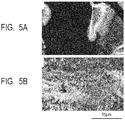
- Observation was made by EBSD and the image capture of an IQ map was performed.
- the IQ map is a two-dimensional image obtained by digitizing the sharpness of a Kikuchi pattern available from a region irradiated with an electron beam. At this time, a signal can be obtained from a crystalline region but no signal can be obtained from an amorphous region and this can be utilized for finding which portion of the manufactured object is amorphous and which portion is crystalline.
- FIG. 5A is an IQ map of a range including a region of the cross-section of Comparative Sample 1 through which the center portion of the laser beam passes.
- FIG. 5B is an IQ map of a range including a region of the cross-section of Sample 1 through which the center portion of the laser beam passes.
- a site corresponding to the center portion of the laser beam is black, showing that the powder layer is constituted of an amorphous substance.
- a site corresponding to the center portion of the laser beam is bright, showing that the powder layer is constituted of a crystalline substance.
- the powder layer can be determined to be crystalline without any problem based on the powder constitution used in the present example, though the crystalline portion has a eutectic structure and therefore seems to have a pattern.
- Comparative Sample 1 obtained by irradiating the surface of the powder layer with the laser beam at a focused position contained an amorphous region more than a crystalline region. It has been revealed that Sample 1 obtained by irradiating the surface of the powder layer with a laser beam at an unfocused position contained a crystalline region relatively more than an amorphous region. As a result, it has been confirmed that irradiation with a laser beam at an unfocused position is effective for obtaining a crystalline manufactured object.
- the present example relates to manufacture under conditions changed between a focused state and an unfocused state.
- manufactured objects shown in Table 1 were produced according to the manufacturing steps of Example 1.
- Table 1 shows condition values obtained by changing a laser power successively from 20 W to 30 W and then to 40 W to achieve sufficient fusion of the powder layer even in a focused state or unfocused state and adjusting a scanning rate range to enable manufacturing at a scanning pitch fixed to 100 ⁇ m.
- Comparative Samples 2 to 5 are those obtained by manufacturing in a focused state (stage height of -1.5 mm in the present example) and Samples 2 to 9 are those obtained by manufacturing in an unfocused state (stage height of -5.0 mm and -7.0 mm in the present example), each an additional sample to Example 1.
- the manufactured objects of the present example have a theoretical density of 5.72 g/cm 3 when they are completely crystalline.
- a relative density 100 ⁇ (density of sample)/(theoretical density) was determined by polishing six faces of each sample manufactured into a 6 ⁇ 6 ⁇ 6 mm size, calculating the density of each sample from the weight and volume thereof, and then dividing it with the theoretical density.
- Crystallization of the manufactured objects was tried by decreasing the scanning rate of a laser stepwise in the numerical order from Comparative Sample 1 to Comparative Sample 5 to give a higher quantity of heat.
- the relative density however, mostly remained unchanged at about 85%.
- Comparative Sample 5 the shape of the manufactured object was not retained due to a high quantity of heat so that the relative density was uncomputable.
- An amorphous substance has a density about 20% lower than that of a crystalline substance. A ratio of the amorphous substance was large so that the relative density mostly remained at about 85%.
- the present example relates to a mutual relation between the shape of a laser-beam fused portion (which can also be expressed as a "solidified portion") and a focused or an unfocused state.
- shape of a laser-beam fused portion as herein employed means a cross-sectional shape of a fused and solidified portion of the powder layer formed by irradiation with a laser beam.
- a fused portion formed by single irradiation with a laser beam in a focused or unfocused state was measured. More specifically, a powder layer was irradiated with a laser corresponding to one line while scanning. A solidified portion obtained by fusion and solidification of the powder was cut at a plane vertical to the scanning direction of a laser and the shape of it was observed. Only the first one layer (thickness of the powder layer: 30 ⁇ m) was manufactured and the shape (D/L) of the laser-beam fused portion was digitized as a ratio of depth D to width L of a portion solidified while biting an alumina plate of a base table.
- the stage height was changed from 0.0 to -7.0 mm; the laser power was changed from 20 to 40 W; and the scanning rate was all fixed at 100 mm/s.
- Table 2 D/L ratio Stage height [mm] 0.0 -1.5 -3.0 -4.0 -5.0 -6.0 -7.0 Laser power [W] 40 1.50 1.76 1.62 1.07 0.61 0.34 0.26 35 1.38 1.70 1.46 0.91 0.46 0.28 0.20 30 1.12 1.67 1.39 0.69 0.38 0.27 Uncomputable 25 0.91 1.44 0.97 0.44 0.22 Uncomputable Uncomputable 20 0.85 1.29 0.66 0.30 0.16 Uncomputable Uncomputable
- Comparative Samples 1 to 5 shown in Examples 1 and 2 can be regarded as a manufactured object obtained by irradiation with a laser beam that actualizes a D/L ratio of 1.29 or a manufactured object under the conditions close thereto. This suggests that an amorphous-rich manufactured object is obtained by irradiation with a laser beam under conditions actualizing a D/L value of 1.29.
- the fused portion When the fused portion has such a sharp cross-sectional shape, it is presumed to be amorphous because fusion occurs sharply in the depth direction and heat scatters not only in the downward direction but also in all directions at the solidification time, which accelerates rapid cooling. Therefore, even if the D/L ratio is equal to or more than a value (1.0 or more) in the vicinity of the above-described value, the fused portion is presumed to have a similar state.
- stage height is -5.0 mm in an unfocused state
- a D/L ratio is less than 0.7 at any laser power
- fusion occurs mildly in the depth direction, and the degree of rapid cooling is relaxed, thus leading to crystallization.
- the stage height is -6.0 mm and the laser power is from 20 to 25 W and where the stage height is -7.0 mm and the laser power is from 20 to 30 W
- fusion has not occurred in the depth direction and the powder was sintered without solidification into a ball or complete fusion.
- Such a state is found to be unpreferable because it causes a bonding failure with an underlying layer at the time of stacking.
- the stage height depends on an apparatus used so that the values of the present examples are intrinsic to the apparatus used for investigation. What is important is to shift a focal position relative to a powder layer, adjust an intensity distribution of a laser beam with which a powder layer is irradiated, and thereby create a state to give a desired D/L ratio. This means that in an apparatus to be used, a shifting degree of a focal position relative to a powder layer changes, depending on the kind of powder used or the specification of the apparatus.
- a manufactured object having a crystalline substance at a high ratio can be obtained by preventing a metal oxide fused by irradiation with a laser light from becoming amorphous at the time of solidification and therefore a manufactured object which is dense and has less shrinkage at the time of sintering can be produced.
Applications Claiming Priority (3)
| Application Number | Priority Date | Filing Date | Title |
|---|---|---|---|
| JP2017208190 | 2017-10-27 | ||
| JP2018200029A JP7277103B2 (ja) | 2017-10-27 | 2018-10-24 | セラミックス造形物の製造方法 |
| PCT/JP2018/039993 WO2019083042A1 (fr) | 2017-10-27 | 2018-10-26 | Procédé de production d'un objet moulé en céramique |
Publications (3)
| Publication Number | Publication Date |
|---|---|
| EP3702121A1 true EP3702121A1 (fr) | 2020-09-02 |
| EP3702121A4 EP3702121A4 (fr) | 2021-08-25 |
| EP3702121B1 EP3702121B1 (fr) | 2023-03-22 |
Family
ID=66670093
Family Applications (2)
| Application Number | Title | Priority Date | Filing Date |
|---|---|---|---|
| EP18870824.2A Active EP3702121B1 (fr) | 2017-10-27 | 2018-10-26 | Procédé de production d'un objet moulé en céramique |
| EP18869737.9A Active EP3702120B1 (fr) | 2017-10-27 | 2018-10-26 | Procédé de production d'un objet moulé |
Family Applications After (1)
| Application Number | Title | Priority Date | Filing Date |
|---|---|---|---|
| EP18869737.9A Active EP3702120B1 (fr) | 2017-10-27 | 2018-10-26 | Procédé de production d'un objet moulé |
Country Status (4)
| Country | Link |
|---|---|
| US (2) | US20200247005A1 (fr) |
| EP (2) | EP3702121B1 (fr) |
| JP (2) | JP7366529B2 (fr) |
| CN (2) | CN111436197B (fr) |
Cited By (1)
| Publication number | Priority date | Publication date | Assignee | Title |
|---|---|---|---|---|
| EP3636403A4 (fr) * | 2017-07-14 | 2021-03-17 | Canon Kabushiki Kaisha | Poudre pour façonnage de céramique, article façonné en céramique et son procédé de fabrication |
Families Citing this family (7)
| Publication number | Priority date | Publication date | Assignee | Title |
|---|---|---|---|---|
| DE102019005605A1 (de) * | 2019-08-09 | 2021-02-11 | Ing3D Ug | Verfahren zur Herstellung eines additiv gefertigten Produkts aus einem mineralischen Ausgangsmaterial mittels direkter Laserversinterung sowie ein nach diesem Verfahren hergestelltes Leichtbauteil |
| CN114585596B (zh) * | 2019-10-23 | 2024-01-19 | 佳能株式会社 | 制造陶瓷制品的方法,含金属成分的液体,制造陶瓷制品的套件和陶瓷制品 |
| CN111689764B (zh) * | 2020-07-06 | 2022-05-31 | 南京理工大学 | 一种低成本激光选区熔化用陶瓷粉末制备及其离焦成形方法 |
| US20220024135A1 (en) * | 2020-07-23 | 2022-01-27 | General Electric Company | System and method of additively manufacturing a component with multiple processing strategies |
| CN111922339A (zh) * | 2020-09-04 | 2020-11-13 | 杭州德迪智能科技有限公司 | 粉末床3d打印方法及设备 |
| JP2023020486A (ja) * | 2021-07-30 | 2023-02-09 | 三菱重工業株式会社 | 積層造形方法及び積層造形装置 |
| US11865769B2 (en) * | 2021-12-07 | 2024-01-09 | Hewlett-Packard Development Company, L.P. | Weak material phases |
Family Cites Families (33)
| Publication number | Priority date | Publication date | Assignee | Title |
|---|---|---|---|---|
| ATE138294T1 (de) | 1986-10-17 | 1996-06-15 | Univ Texas | Verfahren und vorrichtung zur herstellung von gesinterten formkörpern durch teilsinterung |
| US20020195746A1 (en) * | 2001-06-22 | 2002-12-26 | Hull Charles W. | Recoating system for using high viscosity build materials in solid freeform fabrication |
| JP2010114472A (ja) * | 2003-06-30 | 2010-05-20 | Advanced Lcd Technologies Development Center Co Ltd | 結晶化方法 |
| DE102004012682A1 (de) * | 2004-03-16 | 2005-10-06 | Degussa Ag | Verfahren zur Herstellung von dreidimensionalen Objekten mittels Lasertechnik und Auftragen eines Absorbers per Inkjet-Verfahren |
| JP2006237525A (ja) * | 2005-02-28 | 2006-09-07 | Nec Lcd Technologies Ltd | レーザ照射方法及び装置 |
| EP1772210A3 (fr) * | 2005-09-30 | 2008-05-28 | General Electric Company | Noyaux de fonderie et procédé pour leur fabrication |
| JP4655063B2 (ja) | 2007-05-24 | 2011-03-23 | パナソニック電工株式会社 | 三次元形状造形物の製造方法 |
| DE102007024469B4 (de) * | 2007-05-25 | 2009-04-23 | Eos Gmbh Electro Optical Systems | Verfahren zum schichtweisen Herstellen eines dreidimensionalen Objekts |
| DE102008021507A1 (de) * | 2008-04-30 | 2009-11-05 | Fraunhofer-Gesellschaft zur Förderung der angewandten Forschung e.V. | Verfahren zur Herstellung von keramischen Objekten mittels selektiven Laserschmelzens |
| US9889012B2 (en) * | 2009-07-23 | 2018-02-13 | Didier NIMAL | Biomedical device, method for manufacturing the same and use thereof |
| WO2011010189A1 (fr) * | 2009-07-23 | 2011-01-27 | Didier Nimal | Dispositif médical et procédé de fabrication et dutilisation associé |
| EP2292357B1 (fr) * | 2009-08-10 | 2016-04-06 | BEGO Bremer Goldschlägerei Wilh.-Herbst GmbH & Co KG | Article céramique et procédés de production de cet article |
| EP2335848B1 (fr) | 2009-12-04 | 2014-08-20 | SLM Solutions GmbH | Unité de rayonnement optique pour une installation destinée à la fabrication de pièces à usiner par rayonnement de couches de pulvérisation avec un rayonnement laser |
| US20120133080A1 (en) * | 2010-11-29 | 2012-05-31 | 3D Systems, Inc. | Additive Manufacturing Methods for Improved Curl Control and Sidewall Quality |
| CN102432302B (zh) * | 2011-09-08 | 2013-04-17 | 大连理工大学 | 一种激光束近净成形陶瓷结构的方法 |
| JP6306603B2 (ja) * | 2012-11-08 | 2018-04-04 | ディーディーエム システムズ, インコーポレイテッド | 3次元オブジェクトを加工するためのシステムおよび方法 |
| US9527242B2 (en) * | 2012-11-21 | 2016-12-27 | Stratasys, Inc. | Method for printing three-dimensional parts wtih crystallization kinetics control |
| FR2998819B1 (fr) * | 2012-11-30 | 2020-01-31 | Association Pour La Recherche Et Le Developpement De Methodes Et Processus Industriels "Armines" | Procede de fusion de poudre avec chauffage de la zone adjacente au bain |
| FR2998818B1 (fr) | 2012-11-30 | 2020-01-31 | Association Pour La Recherche Et Le Developpement De Methodes Et Processus Industriels "Armines" | Procede de fabrication d'une piece par fusion de poudre les particules de poudre arrivant froides dans le bain |
| JP6200969B2 (ja) | 2013-02-27 | 2017-09-20 | エスエルエム ソルーションズ グループ アーゲー | 調整された微細構造を備えるワークピースの製造装置及び製造方法 |
| CN103193486B (zh) * | 2013-03-18 | 2014-06-11 | 大连理工大学 | 一种激光近净成形Al2O3-ZrO2共晶陶瓷结构件的方法 |
| GB201316815D0 (en) | 2013-09-23 | 2013-11-06 | Renishaw Plc | Additive manufacturing apparatus and method |
| JP6391317B2 (ja) * | 2014-06-26 | 2018-09-19 | ポリプラスチックス株式会社 | 複合成形品及びその製造方法 |
| CN107438495B (zh) | 2015-02-12 | 2021-02-05 | 格罗弗治公司 | 云控制激光制造 |
| KR102223993B1 (ko) * | 2015-04-30 | 2021-03-05 | 휴렛-팩커드 디벨롭먼트 컴퍼니, 엘.피. | 다중-구조의 3d 물체의 프린팅 |
| CN104831276B (zh) * | 2015-05-28 | 2017-08-01 | 山东建筑大学 | 一种通过激光重熔制备非晶化梯度复合材料的方法 |
| EP3120967B1 (fr) | 2015-07-20 | 2019-06-12 | SLM Solutions Group AG | Procédé et dispositif pour commander un système d'irradiation en fonction d'une géométrie de la pièce à fabriquer |
| JP6797642B2 (ja) * | 2015-12-10 | 2020-12-09 | キヤノン株式会社 | 原料粉体の処理方法、および三次元造形物の製造方法 |
| JP6664650B2 (ja) | 2016-01-18 | 2020-03-13 | 国立研究開発法人産業技術総合研究所 | 造形物の製造方法 |
| JP6836101B2 (ja) * | 2016-01-22 | 2021-02-24 | セイコーエプソン株式会社 | 三次元造形物の製造方法 |
| WO2017143005A1 (fr) * | 2016-02-16 | 2017-08-24 | Arizona Board Of Regents On Behalf Of Arizona State University | Fabrication de composants en métal ou en céramique par impression 3d avec supports solubles d'un matériau différent |
| US10611092B2 (en) * | 2017-01-05 | 2020-04-07 | Velo3D, Inc. | Optics in three-dimensional printing |
| US20180281237A1 (en) * | 2017-03-28 | 2018-10-04 | Velo3D, Inc. | Material manipulation in three-dimensional printing |
-
2018
- 2018-10-24 JP JP2018200040A patent/JP7366529B2/ja active Active
- 2018-10-24 JP JP2018200029A patent/JP7277103B2/ja active Active
- 2018-10-26 EP EP18870824.2A patent/EP3702121B1/fr active Active
- 2018-10-26 EP EP18869737.9A patent/EP3702120B1/fr active Active
- 2018-10-26 CN CN201880069821.7A patent/CN111436197B/zh active Active
- 2018-10-26 CN CN201880069808.1A patent/CN111278618B/zh active Active
-
2020
- 2020-04-22 US US16/855,922 patent/US20200247005A1/en active Pending
- 2020-04-22 US US16/855,865 patent/US11813769B2/en active Active
Cited By (2)
| Publication number | Priority date | Publication date | Assignee | Title |
|---|---|---|---|---|
| EP3636403A4 (fr) * | 2017-07-14 | 2021-03-17 | Canon Kabushiki Kaisha | Poudre pour façonnage de céramique, article façonné en céramique et son procédé de fabrication |
| US11718567B2 (en) | 2017-07-14 | 2023-08-08 | Canon Kabushiki Kaisha | Powder for ceramic manufacturing, ceramic manufactured object, and manufacturing method thereof |
Also Published As
| Publication number | Publication date |
|---|---|
| US20200247005A1 (en) | 2020-08-06 |
| EP3702120A1 (fr) | 2020-09-02 |
| CN111278618A (zh) | 2020-06-12 |
| US11813769B2 (en) | 2023-11-14 |
| JP7277103B2 (ja) | 2023-05-18 |
| US20200247004A1 (en) | 2020-08-06 |
| CN111436197A (zh) | 2020-07-21 |
| EP3702120A4 (fr) | 2021-08-04 |
| CN111436197B (zh) | 2022-08-02 |
| EP3702121A4 (fr) | 2021-08-25 |
| JP2019081358A (ja) | 2019-05-30 |
| JP2019081357A (ja) | 2019-05-30 |
| EP3702121B1 (fr) | 2023-03-22 |
| CN111278618B (zh) | 2023-02-28 |
| EP3702120B1 (fr) | 2023-02-15 |
| JP7366529B2 (ja) | 2023-10-23 |
Similar Documents
| Publication | Publication Date | Title |
|---|---|---|
| EP3702121B1 (fr) | Procédé de production d'un objet moulé en céramique | |
| JP7383738B2 (ja) | セラミックス造形用粉体、セラミックス造形物、およびその製造方法 | |
| US11440850B2 (en) | Powder for additive modeling, structure, semiconductor production device component, and semiconductor production device | |
| JP2019019051A (ja) | セラミックス造形用粉体、セラミックス造形物、およびその製造方法 | |
| WO2019091086A1 (fr) | Procédé de formation d'une structure poreuse fine en métal basé sur la fusion sélective par laser | |
| EP2292357A1 (fr) | Article céramique ou verre-céramique et procédés de production de cet article | |
| DE19681075B4 (de) | Verfahren zur Herstellung von Halbleiterteilchen und Vorrichtung zur Durchführung des Verfahrens | |
| DE102014208565A1 (de) | Schnellprototypenbau-Modell, Pulver-Schnellprototypenbau-Vorrichtung und Pulver-Schnellprototypenbau-Verfahren | |
| CN111036905A (zh) | 利用逐层多次激光重熔提高致密度并避免孔洞缺陷的方法 | |
| US20240100736A1 (en) | Shaping method and shaping powder material | |
| US20210309575A1 (en) | Ceramic article production method and ceramic article | |
| JP2023168446A (ja) | セラミックス粉体、セラミックス粉体の製造方法およびセラミックス粉体を用いたセラミックス構造物の製造方法 | |
| CN1441522A (zh) | 复合激光杆及其制造方法和带有复合激光杆的激光装置 | |
| WO2019083042A1 (fr) | Procédé de production d'un objet moulé en céramique | |
| CN106626379A (zh) | 激光制造聚酰胺三维物体的方法和装置 | |
| JP2019181930A (ja) | セラミックス粉体、セラミックス粉体の製造方法およびセラミックス粉体を用いたセラミックス構造物の製造方法 | |
| Liu et al. | Fabrication and Process Monitoring of 316L Stainless Steel by Laser Powder Bed Fusion with µ-Helix Scanning Strategy and Narrow Scanning Line Intervals | |
| US20240033968A1 (en) | Method of producing manufactured object and manufactured object | |
| JP2022160961A (ja) | 導電性に優れた積層造形用の銅合金粉末 | |
| Li et al. | Evaluation of Microstructure and Properties for Multi-Materials Laser Densification of Dental Restoration 159 | |
| Streek et al. | Laser micro sintering-upgrade of the technology | |
| DE4236827A1 (de) | Vorrichtung zur Herstellung multikristalliner Halbleiter-Blöcke mit kolumnarer Kristallstruktur | |
| JP7459645B2 (ja) | 金属積層造形物の製造方法および金属積層造形物、並びにこれを用いた部材 | |
| US20220379369A1 (en) | Casting core containing ceramic and method for manufacturing cast article using the same | |
| JP2021185022A (ja) | 3次元焼成物の製作方法 |
Legal Events
| Date | Code | Title | Description |
|---|---|---|---|
| STAA | Information on the status of an ep patent application or granted ep patent |
Free format text: STATUS: THE INTERNATIONAL PUBLICATION HAS BEEN MADE |
|
| PUAI | Public reference made under article 153(3) epc to a published international application that has entered the european phase |
Free format text: ORIGINAL CODE: 0009012 |
|
| STAA | Information on the status of an ep patent application or granted ep patent |
Free format text: STATUS: REQUEST FOR EXAMINATION WAS MADE |
|
| 17P | Request for examination filed |
Effective date: 20200527 |
|
| AK | Designated contracting states |
Kind code of ref document: A1 Designated state(s): AL AT BE BG CH CY CZ DE DK EE ES FI FR GB GR HR HU IE IS IT LI LT LU LV MC MK MT NL NO PL PT RO RS SE SI SK SM TR |
|
| AX | Request for extension of the european patent |
Extension state: BA ME |
|
| DAV | Request for validation of the european patent (deleted) | ||
| DAX | Request for extension of the european patent (deleted) | ||
| REG | Reference to a national code |
Ref country code: DE Ref legal event code: R079 Ref document number: 602018047603 Country of ref document: DE Free format text: PREVIOUS MAIN CLASS: B28B0001300000 Ipc: B28B0001000000 |
|
| A4 | Supplementary search report drawn up and despatched |
Effective date: 20210722 |
|
| RIC1 | Information provided on ipc code assigned before grant |
Ipc: B28B 1/00 20060101AFI20210716BHEP Ipc: B28B 1/30 20060101ALI20210716BHEP Ipc: B33Y 10/00 20150101ALI20210716BHEP Ipc: B33Y 80/00 20150101ALI20210716BHEP Ipc: C04B 35/64 20060101ALI20210716BHEP Ipc: B29C 64/153 20170101ALI20210716BHEP Ipc: B29C 64/268 20170101ALI20210716BHEP Ipc: B29C 64/393 20170101ALI20210716BHEP Ipc: B33Y 30/00 20150101ALI20210716BHEP Ipc: B33Y 50/02 20150101ALI20210716BHEP Ipc: C03B 19/00 20060101ALI20210716BHEP Ipc: C03C 3/12 20060101ALI20210716BHEP Ipc: C03C 10/00 20060101ALI20210716BHEP Ipc: C04B 35/111 20060101ALI20210716BHEP Ipc: C04B 35/117 20060101ALI20210716BHEP Ipc: C04B 35/653 20060101ALI20210716BHEP |
|
| GRAP | Despatch of communication of intention to grant a patent |
Free format text: ORIGINAL CODE: EPIDOSNIGR1 |
|
| STAA | Information on the status of an ep patent application or granted ep patent |
Free format text: STATUS: GRANT OF PATENT IS INTENDED |
|
| INTG | Intention to grant announced |
Effective date: 20221007 |
|
| GRAS | Grant fee paid |
Free format text: ORIGINAL CODE: EPIDOSNIGR3 |
|
| GRAA | (expected) grant |
Free format text: ORIGINAL CODE: 0009210 |
|
| STAA | Information on the status of an ep patent application or granted ep patent |
Free format text: STATUS: THE PATENT HAS BEEN GRANTED |
|
| AK | Designated contracting states |
Kind code of ref document: B1 Designated state(s): AL AT BE BG CH CY CZ DE DK EE ES FI FR GB GR HR HU IE IS IT LI LT LU LV MC MK MT NL NO PL PT RO RS SE SI SK SM TR |
|
| REG | Reference to a national code |
Ref country code: GB Ref legal event code: FG4D |
|
| REG | Reference to a national code |
Ref country code: CH Ref legal event code: EP |
|
| REG | Reference to a national code |
Ref country code: DE Ref legal event code: R096 Ref document number: 602018047603 Country of ref document: DE |
|
| REG | Reference to a national code |
Ref country code: IE Ref legal event code: FG4D |
|
| REG | Reference to a national code |
Ref country code: AT Ref legal event code: REF Ref document number: 1555015 Country of ref document: AT Kind code of ref document: T Effective date: 20230415 |
|
| REG | Reference to a national code |
Ref country code: LT Ref legal event code: MG9D |
|
| REG | Reference to a national code |
Ref country code: NL Ref legal event code: MP Effective date: 20230322 |
|
| PG25 | Lapsed in a contracting state [announced via postgrant information from national office to epo] |
Ref country code: RS Free format text: LAPSE BECAUSE OF FAILURE TO SUBMIT A TRANSLATION OF THE DESCRIPTION OR TO PAY THE FEE WITHIN THE PRESCRIBED TIME-LIMIT Effective date: 20230322 Ref country code: NO Free format text: LAPSE BECAUSE OF FAILURE TO SUBMIT A TRANSLATION OF THE DESCRIPTION OR TO PAY THE FEE WITHIN THE PRESCRIBED TIME-LIMIT Effective date: 20230622 Ref country code: LV Free format text: LAPSE BECAUSE OF FAILURE TO SUBMIT A TRANSLATION OF THE DESCRIPTION OR TO PAY THE FEE WITHIN THE PRESCRIBED TIME-LIMIT Effective date: 20230322 Ref country code: LT Free format text: LAPSE BECAUSE OF FAILURE TO SUBMIT A TRANSLATION OF THE DESCRIPTION OR TO PAY THE FEE WITHIN THE PRESCRIBED TIME-LIMIT Effective date: 20230322 Ref country code: HR Free format text: LAPSE BECAUSE OF FAILURE TO SUBMIT A TRANSLATION OF THE DESCRIPTION OR TO PAY THE FEE WITHIN THE PRESCRIBED TIME-LIMIT Effective date: 20230322 |
|
| REG | Reference to a national code |
Ref country code: AT Ref legal event code: MK05 Ref document number: 1555015 Country of ref document: AT Kind code of ref document: T Effective date: 20230322 |
|
| PG25 | Lapsed in a contracting state [announced via postgrant information from national office to epo] |
Ref country code: SE Free format text: LAPSE BECAUSE OF FAILURE TO SUBMIT A TRANSLATION OF THE DESCRIPTION OR TO PAY THE FEE WITHIN THE PRESCRIBED TIME-LIMIT Effective date: 20230322 Ref country code: NL Free format text: LAPSE BECAUSE OF FAILURE TO SUBMIT A TRANSLATION OF THE DESCRIPTION OR TO PAY THE FEE WITHIN THE PRESCRIBED TIME-LIMIT Effective date: 20230322 Ref country code: GR Free format text: LAPSE BECAUSE OF FAILURE TO SUBMIT A TRANSLATION OF THE DESCRIPTION OR TO PAY THE FEE WITHIN THE PRESCRIBED TIME-LIMIT Effective date: 20230623 Ref country code: FI Free format text: LAPSE BECAUSE OF FAILURE TO SUBMIT A TRANSLATION OF THE DESCRIPTION OR TO PAY THE FEE WITHIN THE PRESCRIBED TIME-LIMIT Effective date: 20230322 |
|
| PG25 | Lapsed in a contracting state [announced via postgrant information from national office to epo] |
Ref country code: SM Free format text: LAPSE BECAUSE OF FAILURE TO SUBMIT A TRANSLATION OF THE DESCRIPTION OR TO PAY THE FEE WITHIN THE PRESCRIBED TIME-LIMIT Effective date: 20230322 Ref country code: RO Free format text: LAPSE BECAUSE OF FAILURE TO SUBMIT A TRANSLATION OF THE DESCRIPTION OR TO PAY THE FEE WITHIN THE PRESCRIBED TIME-LIMIT Effective date: 20230322 Ref country code: PT Free format text: LAPSE BECAUSE OF FAILURE TO SUBMIT A TRANSLATION OF THE DESCRIPTION OR TO PAY THE FEE WITHIN THE PRESCRIBED TIME-LIMIT Effective date: 20230724 Ref country code: ES Free format text: LAPSE BECAUSE OF FAILURE TO SUBMIT A TRANSLATION OF THE DESCRIPTION OR TO PAY THE FEE WITHIN THE PRESCRIBED TIME-LIMIT Effective date: 20230322 Ref country code: EE Free format text: LAPSE BECAUSE OF FAILURE TO SUBMIT A TRANSLATION OF THE DESCRIPTION OR TO PAY THE FEE WITHIN THE PRESCRIBED TIME-LIMIT Effective date: 20230322 Ref country code: AT Free format text: LAPSE BECAUSE OF FAILURE TO SUBMIT A TRANSLATION OF THE DESCRIPTION OR TO PAY THE FEE WITHIN THE PRESCRIBED TIME-LIMIT Effective date: 20230322 |
|
| PG25 | Lapsed in a contracting state [announced via postgrant information from national office to epo] |
Ref country code: SK Free format text: LAPSE BECAUSE OF FAILURE TO SUBMIT A TRANSLATION OF THE DESCRIPTION OR TO PAY THE FEE WITHIN THE PRESCRIBED TIME-LIMIT Effective date: 20230322 Ref country code: PL Free format text: LAPSE BECAUSE OF FAILURE TO SUBMIT A TRANSLATION OF THE DESCRIPTION OR TO PAY THE FEE WITHIN THE PRESCRIBED TIME-LIMIT Effective date: 20230322 Ref country code: IS Free format text: LAPSE BECAUSE OF FAILURE TO SUBMIT A TRANSLATION OF THE DESCRIPTION OR TO PAY THE FEE WITHIN THE PRESCRIBED TIME-LIMIT Effective date: 20230722 |
|
| REG | Reference to a national code |
Ref country code: DE Ref legal event code: R097 Ref document number: 602018047603 Country of ref document: DE |
|
| PLBE | No opposition filed within time limit |
Free format text: ORIGINAL CODE: 0009261 |
|
| STAA | Information on the status of an ep patent application or granted ep patent |
Free format text: STATUS: NO OPPOSITION FILED WITHIN TIME LIMIT |
|
| PG25 | Lapsed in a contracting state [announced via postgrant information from national office to epo] |
Ref country code: SI Free format text: LAPSE BECAUSE OF FAILURE TO SUBMIT A TRANSLATION OF THE DESCRIPTION OR TO PAY THE FEE WITHIN THE PRESCRIBED TIME-LIMIT Effective date: 20230322 Ref country code: DK Free format text: LAPSE BECAUSE OF FAILURE TO SUBMIT A TRANSLATION OF THE DESCRIPTION OR TO PAY THE FEE WITHIN THE PRESCRIBED TIME-LIMIT Effective date: 20230322 Ref country code: CZ Free format text: LAPSE BECAUSE OF FAILURE TO SUBMIT A TRANSLATION OF THE DESCRIPTION OR TO PAY THE FEE WITHIN THE PRESCRIBED TIME-LIMIT Effective date: 20230322 |
|
| PGFP | Annual fee paid to national office [announced via postgrant information from national office to epo] |
Ref country code: DE Payment date: 20230920 Year of fee payment: 6 |
|
| 26N | No opposition filed |
Effective date: 20240102 |