EP3698671B1 - Tellerbesen, kehrvorrichtung und bodenreinigungsmaschine - Google Patents
Tellerbesen, kehrvorrichtung und bodenreinigungsmaschine Download PDFInfo
- Publication number
- EP3698671B1 EP3698671B1 EP20157506.5A EP20157506A EP3698671B1 EP 3698671 B1 EP3698671 B1 EP 3698671B1 EP 20157506 A EP20157506 A EP 20157506A EP 3698671 B1 EP3698671 B1 EP 3698671B1
- Authority
- EP
- European Patent Office
- Prior art keywords
- base body
- shell
- bristles
- sweeping
- floor surface
- Prior art date
- Legal status (The legal status is an assumption and is not a legal conclusion. Google has not performed a legal analysis and makes no representation as to the accuracy of the status listed.)
- Active
Links
Images

Classifications
-
- A—HUMAN NECESSITIES
- A46—BRUSHWARE
- A46B—BRUSHES
- A46B13/00—Brushes with driven brush bodies or carriers
- A46B13/008—Disc-shaped brush bodies
-
- A—HUMAN NECESSITIES
- A46—BRUSHWARE
- A46B—BRUSHES
- A46B13/00—Brushes with driven brush bodies or carriers
- A46B13/02—Brushes with driven brush bodies or carriers power-driven carriers
-
- A—HUMAN NECESSITIES
- A46—BRUSHWARE
- A46B—BRUSHES
- A46B3/00—Brushes characterised by the way in which the bristles are fixed or joined in or on the brush body or carrier
- A46B3/08—Brushes characterised by the way in which the bristles are fixed or joined in or on the brush body or carrier by clamping
- A46B3/10—Brushes characterised by the way in which the bristles are fixed or joined in or on the brush body or carrier by clamping into rings or the like
- A46B3/14—Brushes characterised by the way in which the bristles are fixed or joined in or on the brush body or carrier by clamping into rings or the like specially adapted for street-cleaning or rail-cleaning brooms
-
- A—HUMAN NECESSITIES
- A46—BRUSHWARE
- A46B—BRUSHES
- A46B9/00—Arrangements of the bristles in the brush body
- A46B9/08—Supports or guides for bristles
-
- A—HUMAN NECESSITIES
- A47—FURNITURE; DOMESTIC ARTICLES OR APPLIANCES; COFFEE MILLS; SPICE MILLS; SUCTION CLEANERS IN GENERAL
- A47L—DOMESTIC WASHING OR CLEANING; SUCTION CLEANERS IN GENERAL
- A47L11/00—Machines for cleaning floors, carpets, furniture, walls, or wall coverings
- A47L11/24—Floor-sweeping machines, motor-driven
-
- A—HUMAN NECESSITIES
- A47—FURNITURE; DOMESTIC ARTICLES OR APPLIANCES; COFFEE MILLS; SPICE MILLS; SUCTION CLEANERS IN GENERAL
- A47L—DOMESTIC WASHING OR CLEANING; SUCTION CLEANERS IN GENERAL
- A47L11/00—Machines for cleaning floors, carpets, furniture, walls, or wall coverings
- A47L11/28—Floor-scrubbing machines, motor-driven
- A47L11/282—Floor-scrubbing machines, motor-driven having rotary tools
- A47L11/283—Floor-scrubbing machines, motor-driven having rotary tools the tools being disc brushes
-
- A—HUMAN NECESSITIES
- A47—FURNITURE; DOMESTIC ARTICLES OR APPLIANCES; COFFEE MILLS; SPICE MILLS; SUCTION CLEANERS IN GENERAL
- A47L—DOMESTIC WASHING OR CLEANING; SUCTION CLEANERS IN GENERAL
- A47L11/00—Machines for cleaning floors, carpets, furniture, walls, or wall coverings
- A47L11/40—Parts or details of machines not provided for in groups A47L11/02 - A47L11/38, or not restricted to one of these groups, e.g. handles, arrangements of switches, skirts, buffers, levers
- A47L11/4036—Parts or details of the surface treating tools
- A47L11/4038—Disk shaped surface treating tools
-
- A—HUMAN NECESSITIES
- A47—FURNITURE; DOMESTIC ARTICLES OR APPLIANCES; COFFEE MILLS; SPICE MILLS; SUCTION CLEANERS IN GENERAL
- A47L—DOMESTIC WASHING OR CLEANING; SUCTION CLEANERS IN GENERAL
- A47L11/00—Machines for cleaning floors, carpets, furniture, walls, or wall coverings
- A47L11/40—Parts or details of machines not provided for in groups A47L11/02 - A47L11/38, or not restricted to one of these groups, e.g. handles, arrangements of switches, skirts, buffers, levers
- A47L11/4077—Skirts or splash guards
-
- E—FIXED CONSTRUCTIONS
- E01—CONSTRUCTION OF ROADS, RAILWAYS, OR BRIDGES
- E01H—STREET CLEANING; CLEANING OF PERMANENT WAYS; CLEANING BEACHES; DISPERSING OR PREVENTING FOG IN GENERAL CLEANING STREET OR RAILWAY FURNITURE OR TUNNEL WALLS
- E01H1/00—Removing undesirable matter from roads or like surfaces, with or without moistening of the surface
- E01H1/02—Brushing apparatus, e.g. with auxiliary instruments for mechanically loosening dirt
- E01H1/05—Brushing apparatus, e.g. with auxiliary instruments for mechanically loosening dirt with driven brushes
- E01H1/053—Brushing apparatus, e.g. with auxiliary instruments for mechanically loosening dirt with driven brushes having vertical axes
-
- A—HUMAN NECESSITIES
- A46—BRUSHWARE
- A46B—BRUSHES
- A46B2200/00—Brushes characterized by their functions, uses or applications
- A46B2200/30—Brushes for cleaning or polishing
- A46B2200/3026—Dusting brush
-
- A—HUMAN NECESSITIES
- A46—BRUSHWARE
- A46B—BRUSHES
- A46B2200/00—Brushes characterized by their functions, uses or applications
- A46B2200/30—Brushes for cleaning or polishing
- A46B2200/3066—Brush specifically designed for use with street cleaning machinery
-
- A—HUMAN NECESSITIES
- A47—FURNITURE; DOMESTIC ARTICLES OR APPLIANCES; COFFEE MILLS; SPICE MILLS; SUCTION CLEANERS IN GENERAL
- A47L—DOMESTIC WASHING OR CLEANING; SUCTION CLEANERS IN GENERAL
- A47L11/00—Machines for cleaning floors, carpets, furniture, walls, or wall coverings
- A47L11/40—Parts or details of machines not provided for in groups A47L11/02 - A47L11/38, or not restricted to one of these groups, e.g. handles, arrangements of switches, skirts, buffers, levers
- A47L11/4013—Contaminants collecting devices, i.e. hoppers, tanks or the like
-
- A—HUMAN NECESSITIES
- A47—FURNITURE; DOMESTIC ARTICLES OR APPLIANCES; COFFEE MILLS; SPICE MILLS; SUCTION CLEANERS IN GENERAL
- A47L—DOMESTIC WASHING OR CLEANING; SUCTION CLEANERS IN GENERAL
- A47L9/00—Details or accessories of suction cleaners, e.g. mechanical means for controlling the suction or for effecting pulsating action; Storing devices specially adapted to suction cleaners or parts thereof; Carrying-vehicles specially adapted for suction cleaners
- A47L9/02—Nozzles
- A47L9/04—Nozzles with driven brushes or agitators
- A47L9/0461—Dust-loosening tools, e.g. agitators, brushes
- A47L9/0466—Rotating tools
- A47L9/0472—Discs
Definitions
- the present invention relates to a disc broom, a sweeping device and a floor cleaning machine.
- Disc brooms are known from the prior art. For example, disc brooms are used in sweeping devices of floor cleaning machines, whereby they are driven in rotation in order to convey sweepings on a floor surface to be cleaned with their bristles in the direction of a receiving device of the floor cleaning machine, so that the receiving device can pick up the sweepings from the floor surface to be cleaned.
- the bristles of the disc brushes move around their axis of rotation.
- the movement of the bristles around the axis of rotation in turn creates an air flow into the area of the bristles and then radially away from the bristles, so that the sweepings can be whirled up before they can be picked up by the collecting device.
- the sweepings contain a high proportion of dust
- whirling up the sweepings leads to whirling dust, which can float in the air for a relatively long time and settle widely on surfaces. Whirling up dust should, however, be avoided when transporting sweepings.
- a cleaning head of a device is known with which the outer wall of a ship's hull can be cleaned.
- the cleaning head has two rotating brushes with bristles attached to them that extend away from a base body.
- the cleaning head is designed in such a way that a peripheral wall fixed to the housing is provided that extends perpendicularly to the cleaning plane and surrounds the rotating brushes.
- the WO 2014/122339 A1 describes a brush which can be attached to the output shaft of a driven tool and which has a base body from which metal bristle elements extend in the axial direction of the axis of rotation.
- the brush described has a rigid outer shell, the purpose of which is to hold the bristle elements in a shape in which they extend parallel to the axis of rotation of the brush.
- a device is described with which stone surfaces can be cleaned, wherein the device has a rotating brush which is surrounded by a housing rigidly connected to the housing of the device.
- a disc broom with the features of claim 1.
- the disc broom is adapted to be connected to a rotary drive in order to form a sweeping device.
- the disc broom has a base body.
- the base body can be coupled to the rotary drive for rotation about a rotation axis and has a circumferential outer edge.
- the disc broom has bristles which are attached to the base body at one end and extend away from the base body and towards a sweeping plane running perpendicular to the rotation axis.
- the disc broom has a cover element.
- the cover element has a preferably conical sleeve made of a flexible material which extends from the base body, preferably from the outer edge, away and towards the sweeping plane.
- the cover has an inner side facing an interior of the cover.
- the cover has an outer side facing an exterior of the cover. The cover envelops the bristles perpendicular to the axis of rotation such that the bristles are arranged in the interior of the cover.
- the base body can be coupled to the rotary drive for rotation about a rotation axis.
- the rotary drive can drive the base body so that the base body rotates about the rotation axis.
- the base body can have a coupling means for coupling to the rotary drive.
- the coupling means of the base body can have a recess and a circumferential contact surface.
- the circular broom has bristles that are attached to the base body at one end and extend away from the base body and towards a sweeping plane that runs perpendicular to the axis of rotation.
- at least one part of the bristles that is radially outer relative to the axis of rotation runs at an angle to the axis of rotation, so that the free ends of the part of the bristles are at a greater distance from the axis of rotation than the ends that are attached to the base body.
- the attachment of the bristles at one end to the base body ensures that the bristles move about the axis of rotation when the base body rotates about the axis of rotation.
- the movement of the bristles about the axis of rotation enables the bristles, when they engage with a floor surface to be cleaned, to transport debris along the floor surface to be cleaned.
- the extension of the bristles away from the base body and towards the sweeping plane running perpendicular to the axis of rotation ensures that the free ends of the bristles remote from the base body engage with the floor surface to be cleaned and can thus transport debris along the floor surface to be cleaned.
- the circular broom has a cover element with a preferably conical cover, the cover surrounding the bristles. If at least the radially outer part of the bristles extends in an inclined or conical manner away from the base body and towards the sweeping plane, the conical cover is adapted to the course of the bristles.
- the preferably conical shell is made of a flexible material.
- the flexibility of the shell material ensures elastic deformation of the shell over large deformation areas, so that the cover returns to its original shape even after strong deformations.
- the flexibility of the material of the cover means that a section of the cover element can lie flat on the floor surface to be cleaned when it comes into contact with the floor surface to be cleaned, so that sweepings can be transported particularly thoroughly along the floor surface to be cleaned by a surface friction force.
- the flexibility of the material of the cover can ensure that the cover deforms elastically if the cover hits an obstacle as it moves over the floor surface to be cleaned.
- An obstacle can, for example, be a wall that borders the floor surface to be cleaned or a shelf that extends over the floor surface to be cleaned. The elastic deformability of the cover can therefore increase the service life of the cover.
- the cover extends away from the base body and towards the sweeping plane.
- the extension of the cover away from the base body and towards the sweeping plane enables the bristles to be wrapped around the axis of rotation.
- the cover can extend away from the outer edge of the base body.
- the cover can rest against the base body so that when the base body rotates around the axis of rotation, the cover also rotates around the axis of rotation due to frictional forces that can act between the cover and the base body.
- the cover can rest against the base body and be attached to it so that when the base body rotates, the cover rotates together with the base body around the axis of rotation.
- the shell has an inner side and an outer side.
- the inner side faces an interior of the shell and the outer side faces an exterior of the shell.
- the shell can separate the interior of the shell from the exterior of the shell.
- the cover encases the bristles perpendicular to the axis of rotation such that the bristles are arranged inside the cover. Enclosing the bristles perpendicular to the axis of rotation by the cover so that the bristles are arranged inside the cover can minimize air flows towards and away from the bristles.
- the Cover reduces air currents between the inside of the cover and the outside of the cover. The whirling up of sweepings before they can be picked up by the collecting device is also minimized by reducing the air currents. Thus, in the event that the sweepings have a high dust content, the amount of whirled up dust can be reduced.
- the cover prevents an air current from entering the area of the bristles and the air from being accelerated radially out of the area of the bristles by the rotation of the disc broom. Because such a flow is prevented, the disc broom according to the invention causes significantly less dust whirling up during operation than with brooms according to the prior art.
- the disc broom can reliably transport sweepings and avoids dust being thrown up or at least keeps the amount of dust being thrown up to a minimum.
- the base body has an upper side facing away from the interior of the casing and a lower side facing the interior of the casing, wherein, when the base body is coupled to the rotary drive, there is no fluid connection through the base body between the interior of the casing and the upper side of the base body.
- the free ends of the bristles remote from the base body are arranged in the sweeping plane.
- the arrangement of the free ends of the bristles remote from the base body in the sweeping plane enables the free ends of the bristles to move about the axis of rotation in the sweeping plane.
- a movement of the free ends of the bristles about the axis of rotation in the sweeping plane enables precise engagement of the free ends of the bristles with the floor surface to be cleaned.
- a circumferential casing section of the casing forms a casing angle of at least 5 and at most 85 degrees, preferably at least 20 and at most 70 degrees, particularly preferably at least 35 and at most 55 degrees, with the rotation axis.
- a casing angle of at least 5 degrees ensures that when a section of the cover element engages with the floor surface to be cleaned, the casing section away from the axis of rotation and towards the outside of the casing. This effect increases with increasing casing angle.
- a casing angle of 85 degrees or less ensures that the bristles are wrapped around the axis of rotation by the casing, even if the casing is elastically deformed. If the casing angle is further reduced, the bristles are wrapped around the axis of rotation by the casing, even if the casing is elastically deformed to a greater extent.
- the flexible material is made of natural rubber. Natural rubber is a particularly flexible and wear-resistant material.
- the flexible material can be made entirely or at least partially from natural rubber.
- the natural rubber can be vulcanized. A vulcanized natural rubber provides almost purely elastic deformation behavior over wide deformation ranges.
- the flexible material can be made of Linatex. Linatex has proven to be particularly advantageous when used as a flexible material for the conical shell. When using Linatex, the shell has optimal flexibility and durability while at the same time having high sweeping effects.
- the present invention is not limited to the flexible material being made of natural rubber.
- the flexible material can also be made entirely or at least partially from synthetic rubber.
- the present invention is not limited to the flexible material being made of natural rubber or synthetic rubber.
- the flexible material can also be made of other elastomers.
- the flexible material has a glass transition temperature of at most 0 °C.
- a glass transition temperature of at most 0 °C ensures that the flexible material is elastic at temperatures above 0 °C. If the flexible material is an elastomer, a glass transition temperature of at most 0 °C ensures that the flexible material is used in the rubber-elastic range at temperatures above 0 °C. It is particularly advantageous if the flexible material has a glass transition temperature of at most -30 °C, as this allows the cover to be elastically deformed, even if the disc broom is used outdoors in severe frost.
- the flexible material has an E-modulus of at most 5 GPa.
- An E-modulus of at most 5 GPa ensures that the shell has a low resistance to elastic deformation, so that the shell can be Contact with an obstacle and the shell and the obstacle are not plastically deformed.
- the casing is designed as a closed surface, so that there is no fluid connection through the casing between the outside of the casing and the inside of the casing.
- air flows through the casing towards the bristles and through the casing away from the bristles can be particularly reliably prevented, so that the whirling up of the sweepings can be further reduced.
- the cover element has a fastening region that is fastened to the base body, preferably to the outer edge of the base body.
- the cover element can be fastened to the base body using the fastening region. Fastening the cover element to the base body ensures that the cover element rotates about the axis of rotation when the base body rotates about the axis of rotation.
- the fastening region can be designed to be circumferential, so that the fastening region can be fastened to the outer edge all the way around.
- the fastening region can be designed to be stiffer than the casing, so that the fastening region enables a mechanically stable fastening to the base body and at the same time the casing can be designed to be sufficiently flexible.
- the fastening area is glued and/or stapled to the base body, preferably the outer edge.
- Adhesive bonding represents a simple and mechanically robust material-locking connection. If the fastening area is stapled to the base body, a positive and/or non-positive connection is provided between the fastening area and the base body. For example, the fastening area can be stapled to the base body. Staple the fastening area to the base body is particularly simple and quick. If the fastening area is glued and stapled to the base body, a material-locking and positive and/or non-positive connection is provided between the fastening area and the base body, so that the fastening area and the base body are connected to one another in a particularly mechanically robust manner.
- the object mentioned at the outset is achieved by a sweeping device with the features of claim 11.
- the sweeping device has a disc brush according to the first aspect of the invention and a Rotary drive.
- the base body of the disc brush is coupled to the rotary drive for rotation around the rotation axis.
- the object mentioned at the outset is achieved by a floor cleaning machine with the features of patent claim 12.
- the floor cleaning machine is designed to clean a floor surface of sweepings, in particular dust.
- the floor cleaning machine has a sweeping device according to the second aspect of the invention, a chassis for moving the floor cleaning machine over the floor surface to be cleaned and a sweepings collection device, in particular a dust collection device.
- the circular brush of the sweeping device can be brought into a working position.
- a portion of the bristles and preferably a section of the cover element engage with the floor surface to be cleaned, so that when the base body rotates about the axis of rotation caused by the rotary drive of the sweeping device, sweepings are conveyed from the floor surface to be cleaned through the bristles and the cover element to an entrance of the sweepings collection device, in particular the dust collection device.
- the disc brush of the sweeping device can be moved into a working position.
- the disc brush of the sweeping device can be moved from a transport position into the working position.
- the bristles and the cover element are spaced from the floor surface, so that the floor cleaning machine can be moved towards and away from the floor surface to be cleaned without a subset of the bristles and a section of the cover element engaging with the floor surface.
- a subset of the bristles and preferably a section of the cover element engage with the floor surface to be cleaned.
- the sweeping plane in the working position, is arranged at a sweeping angle of more than 0 degrees to the floor area to be cleaned. With a sweeping angle of more than 0 degrees, the sweepings are transported particularly efficiently and in the direction of the entrance of the sweepings collecting device through the bristles and the cover element.
- the sweepings collection device in particular the dust collection device, is designed to convey sweepings, in particular dust, from the floor area to be cleaned into a collection container. Conveying the sweepings into a collection container ensures that the sweepings can be collected in the floor cleaning machine and transported to a disposal station.
- the floor cleaning machine is a sweeper, a vacuum sweeper, a scrubber or a scrubber-drier. Because the floor cleaning machine can be a sweeper, a vacuum sweeper, a scrubber or a scrubber-drier, different areas of application are provided for the disc brush according to the first aspect of the invention and for the sweeping device according to the second aspect of the invention.
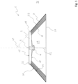
- Figure 1 shows a schematic sectional view of an embodiment of a disc broom 1 according to the invention.
- the disc broom 1 has a base body 3, bristles 5 and a cover element 7.
- the base body 3 has a recess 9 and a circumferential contact surface 11.
- the recess 9 and the contact surface 11 enable a rotatable coupling of the base body 3 about a rotation axis 13.
- the base body also has a top side 15 and a bottom side 17 and a circumferential outer edge 19.
- the bristles 5 are attached at one end to the base body 3 and extend away from the base body 3 and towards a sweeping plane 21 running perpendicular to the rotation axis 13.
- the free ends of the bristles 5 remote from the base body 3 are arranged in the sweeping plane 21 in this embodiment.
- the bristles 5 are inclined to the rotation axis 13, so that the free ends of the bristles 5 are at a greater distance from the rotation axis 13 than the ends that are attached to the base body 3.
- the cover element 7 has a conical shell 23.
- the shell 23 has an inner side 25 and an outer side 27, and the inner side 25 faces an interior 29 of the shell 23.
- the outer side 27 faces an exterior 31 of the shell 23.
- the shell 23 extends away from the outer edge 19 and towards the sweeping plane 21.
- the cover element 7 has a fastening area 33 which is fastened to the outer edge 19 of the base body 3. The fastening area can be glued and/or stapled to the outer edge 19.
- the casing 23 is made of a flexible material.
- the flexible material is made of natural rubber, has a glass transition temperature of at most 0 °C and has an elastic modulus of at most 5 GPa. Particularly high sweeping effects with little whirling up of the sweepings have been shown when the flexible material is made of Linatex.
- the cover 23 envelops the bristles 5 perpendicular to the axis of rotation 13 such that the bristles 5 are arranged in the interior 29 of the cover 23.
- Enveloping the bristles 5 perpendicular to the axis of rotation 13 by the casing 23, so that the bristles 5 are arranged in the interior 29 of the casing 23, can minimize air flows towards and away from the bristles 5.
- the casing 23 reduces air currents between the interior 29 of the casing and the exterior 31 of the casing.
- the whirling up of sweepings before they are collected by a sweepings collecting device 41 is also minimized by reducing the air currents. This means that if the sweepings contain a high proportion of dust, the amount of dust stirred up can be reduced.
- the casing 23 is designed as a closed surface so that there is no fluid connection through the casing 23 between the exterior 31 of the casing 23 and the interior 29 of the casing 23.
- air flows through the casing 23 towards the bristles and through the casing 23 away from the bristles can be particularly effectively prevented, so that the whirling up of the sweepings can be reduced even more significantly.
- the casing 23 has a circumferential casing section 35 which forms a casing angle 49 of 48 degrees with the rotation axis 13.
- a casing angle 49 of 48 degrees is merely an example. In particular, when the casing 23 moves about the rotation axis 13, the casing angle 49 can also assume other values.
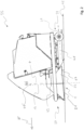
- FIG. 2 shows a schematic side view of a part of an embodiment of a floor cleaning machine according to the invention, wherein the part is designed as a sweeping attachment 35.
- the sweeping attachment 35 has sweeping devices 37, which are each attached to the sides, a chassis 39 and a sweepings collecting device 41, in particular a dust collecting device.
- the sweeping devices 37 have the Figure 1 The cover 23 of the circular broom 1 shown in Figure 2 In addition, the sweeping devices 37 have a rotary drive 43.
- the base body 3 (see Figure 1 ) of the disc brush 1 is coupled to the rotary drive 43 for rotation about the rotation axis 13.
- the sweeping devices 37 are adapted for use as part of a floor cleaning machine, here as part of a sweeping attachment 35.
- the sweeping devices 37 can also be used as part of a sweeping machine, a vacuum sweeper, a scrubbing machine or a scrubbing dryer.
- the chassis 39 is designed to move the sweeping attachment 35 over a floor surface 45 to be cleaned.
- the sweepings collecting device 41 is designed to To convey sweepings, in particular dust, from the floor surface 45 to be cleaned into a receiving container 46 of the sweeping attachment 35.
- the sweeping attachment 35 is designed to clean the floor surface 45 of dust.
- the top side 15 of the base body 3 faces away from the interior 29 of the casing 23 and the bottom side 17 faces the interior 29 of the casing 23. If the base body 3 is connected to the rotary drive 43 as in Figure 2 is coupled, there is no fluid connection through the base body 3 between the interior 29 of the casing 23 and the upper side 15 of the base body 3. By avoiding a fluid connection through the base body 3 when it is coupled to the rotary drive 43, air flows through the base body 3 towards the bristles 5 and through the base body 3 away from the bristles 5 can be prevented when the bristles 5 move about the axis of rotation 13. Preventing air flows through the base body 3 can further reduce the whirling up of the sweepings.
- the disc brush 1 of the sweeping devices 37 can be moved from a transport position to a Figure 2 shown working position.
- the bristles 5 and the cover element 7 are spaced from the floor surface 45 so that the sweeping attachment 35 can move towards and away from the floor surface 45 to be cleaned without a portion of the bristles 5 and a section of the cover element 7 engaging with the floor surface 45.
- the working position a portion of the bristles 5 and a section of the cover element 7 engage with the floor surface 45 to be cleaned.
- the sweeping plane 21 in the embodiment described here is arranged at a sweeping angle 47 of approximately 5 degrees to the floor surface 45 to be cleaned.
- a sweeping angle 47 of 5 degrees is merely an example.
- the sweeping angle 47 can also assume other values.
- the sweeping angle 47 between the sweeping plane 21 and the floor surface 45 to be cleaned corresponds to the angle of inclination 47' of the rotation axis 13 of the disc broom 1.
- the rotation axis 13 is tilted by 5 degrees to the side and by 5 degrees forward in the direction of travel F of the sweeping attachment 35.
- Figure 3 shows in plan view as hatched areas B relative to the direction of travel F of the sweeping attachment 35 those sections of the floor surface 45 to be cleaned with which the partial quantities of the bristles 5 of the disc brush 1 engage due to the inclination of the rotation axes 13.
- These areas B extend over a total of 180 degrees. They also extend 60 degrees inwards towards the middle of the sweeping attachment 35 compared to the direction of travel F and over 30 degrees backwards against the direction of travel F.
- the rotary drives 43 of the sweeping devices 37 are designed such that the disc brushes 1 rotate in opposite directions when they are in engagement with the floor surface 45 to be cleaned such that the bristles 5 located in areas B in engagement with the floor surface 45 to be cleaned move towards the middle of the sweeping attachment 35. This moves dirt located on the floor surface 45 to the middle of the sweeping attachment 35.
Landscapes
- Engineering & Computer Science (AREA)
- Architecture (AREA)
- Civil Engineering (AREA)
- Structural Engineering (AREA)
- Brushes (AREA)
- Nozzles For Electric Vacuum Cleaners (AREA)
- Cleaning In General (AREA)
- Mechanical Engineering (AREA)
Applications Claiming Priority (1)
| Application Number | Priority Date | Filing Date | Title |
|---|---|---|---|
| DE102019104497.9A DE102019104497A1 (de) | 2019-02-21 | 2019-02-21 | Tellerbesen, Kehrvorrichtung und Bodenreinigungsmaschine |
Publications (3)
| Publication Number | Publication Date |
|---|---|
| EP3698671A1 EP3698671A1 (de) | 2020-08-26 |
| EP3698671C0 EP3698671C0 (de) | 2024-11-27 |
| EP3698671B1 true EP3698671B1 (de) | 2024-11-27 |
Family
ID=69630196
Family Applications (1)
| Application Number | Title | Priority Date | Filing Date |
|---|---|---|---|
| EP20157506.5A Active EP3698671B1 (de) | 2019-02-21 | 2020-02-14 | Tellerbesen, kehrvorrichtung und bodenreinigungsmaschine |
Country Status (8)
| Country | Link |
|---|---|
| US (1) | US12167789B2 (enExample) |
| EP (1) | EP3698671B1 (enExample) |
| JP (1) | JP7554561B2 (enExample) |
| KR (1) | KR102869683B1 (enExample) |
| CN (1) | CN111588309A (enExample) |
| AU (1) | AU2020201116B2 (enExample) |
| CA (1) | CA3072863A1 (enExample) |
| DE (1) | DE102019104497A1 (enExample) |
Families Citing this family (2)
| Publication number | Priority date | Publication date | Assignee | Title |
|---|---|---|---|---|
| GB2602066B (en) * | 2020-12-17 | 2023-06-07 | Dyson Technology Ltd | Floor cleaner |
| IT202100008123A1 (it) * | 2021-03-31 | 2022-10-01 | Diversey Inc | Apparecchiatura per la pulizia di pavimenti e rullo pulitore per un’apparecchiatura per la pulizia di pavimenti |
Citations (1)
| Publication number | Priority date | Publication date | Assignee | Title |
|---|---|---|---|---|
| DE3605235C2 (enExample) * | 1986-02-19 | 1992-08-06 | Ing. Haaga Kunststofftechnik Gmbh, 7312 Kirchheim, De |
Family Cites Families (21)
| Publication number | Priority date | Publication date | Assignee | Title |
|---|---|---|---|---|
| US1329474A (en) * | 1918-02-20 | 1920-02-03 | Micheal P Pregler | Scrubbing-machine |
| US3019465A (en) * | 1959-05-28 | 1962-02-06 | Gen Electric | Rug scrubbing tool attachment particularly for floor polishers |
| US3101505A (en) * | 1961-07-18 | 1963-08-27 | Electrolux Corp | Surface treating machine |
| GB1527242A (en) | 1975-03-24 | 1978-10-04 | Butterworth Syst Inc | Rotatable brushes |
| US6202243B1 (en) * | 1999-05-26 | 2001-03-20 | Tennant Company | Surface cleaning machine with multiple control positions |
| US7533435B2 (en) * | 2003-05-14 | 2009-05-19 | Karcher North America, Inc. | Floor treatment apparatus |
| DK2820994T3 (en) | 2004-02-16 | 2017-01-23 | Kärcher North America Inc | Appliance for floor cleaning and treatment |
| DE102006011216B4 (de) * | 2006-03-03 | 2022-11-10 | Electrostar Gmbh | Kehrmaschine und Verfahren zum Ausgleichen von Unebenheiten |
| CN201192316Y (zh) * | 2008-04-29 | 2009-02-11 | 陈静 | 多功能清扫装置 |
| GB2461536A (en) * | 2008-07-01 | 2010-01-06 | Parvaiz Akhtar | Block paving cleaner |
| JP2012085735A (ja) | 2010-10-18 | 2012-05-10 | Suzutec Co Ltd | 手動式掃除機 |
| EP2532788A2 (en) * | 2011-06-08 | 2012-12-12 | Ventac Group | A brush assembly |
| EP2734098B1 (de) * | 2011-07-22 | 2016-09-07 | Alfred Kärcher GmbH & Co. KG | Kehrmaschine mit druckbehälter zur abreinigung des filters |
| ES2484066B1 (es) * | 2013-02-08 | 2015-06-01 | Jaz-Zubiaurre, S.A. | Cepillo industrial rotarorio con recubrimiento exterior |
| FI125878B (fi) * | 2013-06-13 | 2016-03-31 | Dg Diving Group Ltd | Laite ja menetelmä vedenalaisen pinnan käsittelemiseksi |
| CN203379074U (zh) * | 2013-08-15 | 2014-01-08 | 戴勇 | 一种家用扫拖一体机 |
| CN105297658B (zh) * | 2015-11-11 | 2017-06-20 | 郑州中岳机电设备有限公司 | 一种大中型清扫拖地车 |
| CN105342530A (zh) * | 2015-11-25 | 2016-02-24 | 天津市藏原地毯有限公司 | 一种新型的手持式地毯清洁刷 |
| JP2017221240A (ja) | 2016-06-13 | 2017-12-21 | 京葉ビルサービス株式会社 | 床面皮膜除去ブラシおよび床面皮膜除去方法 |
| CN206090419U (zh) * | 2016-08-24 | 2017-04-12 | 天津海天方圆节能技术有限公司 | 一种新型环保清洁车扫盘组件 |
| CN108903849A (zh) * | 2018-09-02 | 2018-11-30 | 安徽风向标清洁设备有限公司 | 一种洗地机专用盘刷 |
-
2019
- 2019-02-21 DE DE102019104497.9A patent/DE102019104497A1/de active Pending
-
2020
- 2020-02-14 EP EP20157506.5A patent/EP3698671B1/de active Active
- 2020-02-17 AU AU2020201116A patent/AU2020201116B2/en active Active
- 2020-02-19 CA CA3072863A patent/CA3072863A1/en active Pending
- 2020-02-19 US US16/794,780 patent/US12167789B2/en active Active
- 2020-02-20 CN CN202010105750.0A patent/CN111588309A/zh active Pending
- 2020-02-20 JP JP2020027098A patent/JP7554561B2/ja active Active
- 2020-02-21 KR KR1020200021505A patent/KR102869683B1/ko active Active
Patent Citations (1)
| Publication number | Priority date | Publication date | Assignee | Title |
|---|---|---|---|---|
| DE3605235C2 (enExample) * | 1986-02-19 | 1992-08-06 | Ing. Haaga Kunststofftechnik Gmbh, 7312 Kirchheim, De |
Also Published As
| Publication number | Publication date |
|---|---|
| KR20200102381A (ko) | 2020-08-31 |
| US20200268138A1 (en) | 2020-08-27 |
| AU2020201116A1 (en) | 2020-09-10 |
| KR102869683B1 (ko) | 2025-10-10 |
| US12167789B2 (en) | 2024-12-17 |
| EP3698671C0 (de) | 2024-11-27 |
| JP2020131038A (ja) | 2020-08-31 |
| JP7554561B2 (ja) | 2024-09-20 |
| EP3698671A1 (de) | 2020-08-26 |
| CA3072863A1 (en) | 2020-08-21 |
| DE102019104497A1 (de) | 2020-08-27 |
| CN111588309A (zh) | 2020-08-28 |
| AU2020201116B2 (en) | 2025-02-27 |
Similar Documents
| Publication | Publication Date | Title |
|---|---|---|
| DE102010037672B4 (de) | Rotierbare Kehrbürste sowie selbsttätig verfahrbares Bodengerät mit einer derartigen Kehrbürste | |
| DE3736536A1 (de) | Kehrmaschine | |
| DE2559983B1 (de) | Boden-,insbesondere Teppichkehrmaschine | |
| DE19617986A1 (de) | Kehrmaschine | |
| EP3698671B1 (de) | Tellerbesen, kehrvorrichtung und bodenreinigungsmaschine | |
| DE102014116989A1 (de) | Staubsaugerseitenbürste und Bodenpflegegerät mit einer Staubsaugerseitenbürste | |
| DE102014102812A1 (de) | Kehrmaschine und Verfahren zum Betreiben einer Kehrmaschine | |
| DE102015114775A1 (de) | Saugroboter | |
| DE69111378T2 (de) | Saugmundstück eines Staubsaugers. | |
| EP3922154B1 (de) | Saugroboter und reinigungsstation | |
| DE102008018441A1 (de) | Kehrmaschine mit Umlenkelement | |
| DE102006037453B4 (de) | Handgeführtes, motorgetriebenes Kehrgerät | |
| WO2008098855A1 (de) | Bürstenkopf eines reinigungsgeräts sowie reinigungsgerät mit einem solchen bürstenkopf | |
| EP2690220B1 (de) | Kehrsaugmaschine mit einer Absaugung für einen Seitenbesen | |
| WO2007144066A1 (de) | Bürste und kehrgerät mit bürste | |
| EP4260756A1 (de) | Reinigungsgerät, kehrbürste für ein reinigungsgerät und verfahren zum betreiben eines reinigungsgeräts | |
| DE102021116683A1 (de) | Bodenreinigungsmaschine | |
| DE202016106335U1 (de) | Bürstenkopf für einen Staubsauger oder einen Saugroboter | |
| DE19959562C1 (de) | Kehrmaschine und Kehrlippe hierfür | |
| EP3011884B1 (de) | Handgeführte kehrmaschine und verwendung eines kupplungsrings in einer handgeführte kehrmaschine | |
| DE29508830U1 (de) | Vorrichtung zum Reinigen eines Gleiskörpers | |
| EP4260757A1 (de) | Reinigungsgerät, kehrbürste für ein reinigungsgerät und verfahren zum betreiben eines reinigungsgeräts | |
| DE102007007844B4 (de) | Bürstenkopf eines Reinigungsgeräts sowie Reinigungsgerät | |
| DE102006028033A1 (de) | Kehrgerät | |
| DE10362036B4 (de) | Besenkörper, Besen und Handfeger |
Legal Events
| Date | Code | Title | Description |
|---|---|---|---|
| PUAI | Public reference made under article 153(3) epc to a published international application that has entered the european phase |
Free format text: ORIGINAL CODE: 0009012 |
|
| STAA | Information on the status of an ep patent application or granted ep patent |
Free format text: STATUS: THE APPLICATION HAS BEEN PUBLISHED |
|
| AK | Designated contracting states |
Kind code of ref document: A1 Designated state(s): AL AT BE BG CH CY CZ DE DK EE ES FI FR GB GR HR HU IE IS IT LI LT LU LV MC MK MT NL NO PL PT RO RS SE SI SK SM TR |
|
| AX | Request for extension of the european patent |
Extension state: BA ME |
|
| STAA | Information on the status of an ep patent application or granted ep patent |
Free format text: STATUS: REQUEST FOR EXAMINATION WAS MADE |
|
| 17P | Request for examination filed |
Effective date: 20210226 |
|
| RBV | Designated contracting states (corrected) |
Designated state(s): AL AT BE BG CH CY CZ DE DK EE ES FI FR GB GR HR HU IE IS IT LI LT LU LV MC MK MT NL NO PL PT RO RS SE SI SK SM TR |
|
| REG | Reference to a national code |
Ref country code: HK Ref legal event code: DE Ref document number: 40036818 Country of ref document: HK |
|
| REG | Reference to a national code |
Ref country code: DE Ref legal event code: R079 Free format text: PREVIOUS MAIN CLASS: A46B0013000000 Ipc: A47L0011400000 Ref document number: 502020009809 Country of ref document: DE |
|
| GRAP | Despatch of communication of intention to grant a patent |
Free format text: ORIGINAL CODE: EPIDOSNIGR1 |
|
| STAA | Information on the status of an ep patent application or granted ep patent |
Free format text: STATUS: GRANT OF PATENT IS INTENDED |
|
| INTG | Intention to grant announced |
Effective date: 20240620 |
|
| RIC1 | Information provided on ipc code assigned before grant |
Ipc: E01H 1/05 20060101ALI20240607BHEP Ipc: A46B 13/02 20060101ALI20240607BHEP Ipc: A46B 3/14 20060101ALI20240607BHEP Ipc: A47L 11/24 20060101ALI20240607BHEP Ipc: A46B 9/08 20060101ALI20240607BHEP Ipc: A46B 13/00 20060101ALI20240607BHEP Ipc: A47L 11/40 20060101AFI20240607BHEP |
|
| GRAS | Grant fee paid |
Free format text: ORIGINAL CODE: EPIDOSNIGR3 |
|
| GRAA | (expected) grant |
Free format text: ORIGINAL CODE: 0009210 |
|
| STAA | Information on the status of an ep patent application or granted ep patent |
Free format text: STATUS: THE PATENT HAS BEEN GRANTED |
|
| AK | Designated contracting states |
Kind code of ref document: B1 Designated state(s): AL AT BE BG CH CY CZ DE DK EE ES FI FR GB GR HR HU IE IS IT LI LT LU LV MC MK MT NL NO PL PT RO RS SE SI SK SM TR |
|
| REG | Reference to a national code |
Ref country code: GB Ref legal event code: FG4D Free format text: NOT ENGLISH |
|
| RIN1 | Information on inventor provided before grant (corrected) |
Inventor name: PROTZ, CARSTEN Inventor name: ULRICH, BERTRAM |
|
| REG | Reference to a national code |
Ref country code: CH Ref legal event code: EP |
|
| REG | Reference to a national code |
Ref country code: DE Ref legal event code: R096 Ref document number: 502020009809 Country of ref document: DE |
|
| REG | Reference to a national code |
Ref country code: IE Ref legal event code: FG4D Free format text: LANGUAGE OF EP DOCUMENT: GERMAN |
|
| U01 | Request for unitary effect filed |
Effective date: 20241204 |
|
| U07 | Unitary effect registered |
Designated state(s): AT BE BG DE DK EE FI FR IT LT LU LV MT NL PT RO SE SI Effective date: 20241213 |
|
| U20 | Renewal fee for the european patent with unitary effect paid |
Year of fee payment: 6 Effective date: 20250224 |
|
| PG25 | Lapsed in a contracting state [announced via postgrant information from national office to epo] |
Ref country code: HR Free format text: LAPSE BECAUSE OF FAILURE TO SUBMIT A TRANSLATION OF THE DESCRIPTION OR TO PAY THE FEE WITHIN THE PRESCRIBED TIME-LIMIT Effective date: 20241127 Ref country code: IS Free format text: LAPSE BECAUSE OF FAILURE TO SUBMIT A TRANSLATION OF THE DESCRIPTION OR TO PAY THE FEE WITHIN THE PRESCRIBED TIME-LIMIT Effective date: 20250327 |
|
| PG25 | Lapsed in a contracting state [announced via postgrant information from national office to epo] |
Ref country code: ES Free format text: LAPSE BECAUSE OF FAILURE TO SUBMIT A TRANSLATION OF THE DESCRIPTION OR TO PAY THE FEE WITHIN THE PRESCRIBED TIME-LIMIT Effective date: 20241127 |
|
| PG25 | Lapsed in a contracting state [announced via postgrant information from national office to epo] |
Ref country code: NO Free format text: LAPSE BECAUSE OF FAILURE TO SUBMIT A TRANSLATION OF THE DESCRIPTION OR TO PAY THE FEE WITHIN THE PRESCRIBED TIME-LIMIT Effective date: 20250227 |
|
| PG25 | Lapsed in a contracting state [announced via postgrant information from national office to epo] |
Ref country code: GR Free format text: LAPSE BECAUSE OF FAILURE TO SUBMIT A TRANSLATION OF THE DESCRIPTION OR TO PAY THE FEE WITHIN THE PRESCRIBED TIME-LIMIT Effective date: 20250228 |
|
| PG25 | Lapsed in a contracting state [announced via postgrant information from national office to epo] |
Ref country code: PL Free format text: LAPSE BECAUSE OF FAILURE TO SUBMIT A TRANSLATION OF THE DESCRIPTION OR TO PAY THE FEE WITHIN THE PRESCRIBED TIME-LIMIT Effective date: 20241127 |
|
| PG25 | Lapsed in a contracting state [announced via postgrant information from national office to epo] |
Ref country code: RS Free format text: LAPSE BECAUSE OF FAILURE TO SUBMIT A TRANSLATION OF THE DESCRIPTION OR TO PAY THE FEE WITHIN THE PRESCRIBED TIME-LIMIT Effective date: 20250227 |
|
| PG25 | Lapsed in a contracting state [announced via postgrant information from national office to epo] |
Ref country code: SM Free format text: LAPSE BECAUSE OF FAILURE TO SUBMIT A TRANSLATION OF THE DESCRIPTION OR TO PAY THE FEE WITHIN THE PRESCRIBED TIME-LIMIT Effective date: 20241127 |
|
| PG25 | Lapsed in a contracting state [announced via postgrant information from national office to epo] |
Ref country code: SK Free format text: LAPSE BECAUSE OF FAILURE TO SUBMIT A TRANSLATION OF THE DESCRIPTION OR TO PAY THE FEE WITHIN THE PRESCRIBED TIME-LIMIT Effective date: 20241127 |
|
| PG25 | Lapsed in a contracting state [announced via postgrant information from national office to epo] |
Ref country code: CZ Free format text: LAPSE BECAUSE OF FAILURE TO SUBMIT A TRANSLATION OF THE DESCRIPTION OR TO PAY THE FEE WITHIN THE PRESCRIBED TIME-LIMIT Effective date: 20241127 |
|
| PG25 | Lapsed in a contracting state [announced via postgrant information from national office to epo] |
Ref country code: MC Free format text: LAPSE BECAUSE OF FAILURE TO SUBMIT A TRANSLATION OF THE DESCRIPTION OR TO PAY THE FEE WITHIN THE PRESCRIBED TIME-LIMIT Effective date: 20241127 |
|
| REG | Reference to a national code |
Ref country code: CH Ref legal event code: PL |
|
| PLBE | No opposition filed within time limit |
Free format text: ORIGINAL CODE: 0009261 |
|
| STAA | Information on the status of an ep patent application or granted ep patent |
Free format text: STATUS: NO OPPOSITION FILED WITHIN TIME LIMIT |
|
| PG25 | Lapsed in a contracting state [announced via postgrant information from national office to epo] |
Ref country code: CH Free format text: LAPSE BECAUSE OF NON-PAYMENT OF DUE FEES Effective date: 20250228 |
|
| GBPC | Gb: european patent ceased through non-payment of renewal fee |
Effective date: 20250227 |
|
| 26N | No opposition filed |
Effective date: 20250828 |