EP3696351A1 - Schlüssel für einen schliesszylinder - Google Patents
Schlüssel für einen schliesszylinder Download PDFInfo
- Publication number
- EP3696351A1 EP3696351A1 EP20154079.6A EP20154079A EP3696351A1 EP 3696351 A1 EP3696351 A1 EP 3696351A1 EP 20154079 A EP20154079 A EP 20154079A EP 3696351 A1 EP3696351 A1 EP 3696351A1
- Authority
- EP
- European Patent Office
- Prior art keywords
- locking
- key
- recesses
- inclination
- orange
- Prior art date
- Legal status (The legal status is an assumption and is not a legal conclusion. Google has not performed a legal analysis and makes no representation as to the accuracy of the status listed.)
- Granted
Links
Images
Classifications
-
- E—FIXED CONSTRUCTIONS
- E05—LOCKS; KEYS; WINDOW OR DOOR FITTINGS; SAFES
- E05B—LOCKS; ACCESSORIES THEREFOR; HANDCUFFS
- E05B19/00—Keys; Accessories therefor
- E05B19/0017—Key profiles
- E05B19/0023—Key profiles characterized by variation of the contact surface between the key and the tumbler pins or plates
-
- E—FIXED CONSTRUCTIONS
- E05—LOCKS; KEYS; WINDOW OR DOOR FITTINGS; SAFES
- E05B—LOCKS; ACCESSORIES THEREFOR; HANDCUFFS
- E05B19/00—Keys; Accessories therefor
- E05B19/0017—Key profiles
- E05B19/0035—Key profiles characterized by longitudinal bit variations
Definitions
- the invention relates to a key for a lock cylinder with a series of lock recesses arranged in a shaft, the lock recesses each being delimited by flank contours and having support surfaces for supporting the locking orange of the lock cylinder.
- a lock cylinder with a key is for example from the WO 2015/114172 A1 known.
- the lock cylinder has several locking elements, the distances between which are different from one another.
- Locking recesses in the key for controlling the locking devices have the same spacing as the locking devices. This is to prevent the insertion force from increasing from locking member to locking member when the key is inserted into the lock cylinder.
- locking recesses are provided for controlling the locking orange of the lock cylinder.
- the locking recesses have locking surfaces for supporting the locking member. Transitions of inclined flanks adjoining the locking surfaces have concavely rounded sliding surfaces. This is to avoid a hook when operating the lock cylinder.
- the disadvantage of the known keys is that the key is held in the inserted state by all locking orange at the same time, since the locking orange generally each have the same dimensions at their ends facing the locking recesses. Removal of the key from the lock cylinder is subject to a high pulling force due to the simultaneous holding of the key by all locking orange against, because all static friction of the individual barrier orange must be resolved at the same time.
- the invention is based on the problem of developing a key of the type mentioned at the beginning in such a way that the withdrawal force is kept as low as possible when the key is completely inserted into the lock cylinder.
- the locking recesses no longer have the same width or no longer have the same angle of inclination of the flank contours, so that a simultaneous activation of the locking orange by the different locking recesses is avoided. Rather, due to the variance of the widths in the lock cylinder, the locking orange is moved in a sequence, since the locking orange each have the same dimensions at their ends facing the locking recesses. The increase in the angle of inclination of the flank contours over the row of locking recesses has the consequence that the locking orange experience different accelerations when the key is removed. As a result, the withdrawal force is kept particularly low when the key is completely inserted into the lock cylinder.
- an orderly loosening of the locking orange when the key is removed can be produced if the increase in the widths of the locking recesses is designed in a prescribed sequence of steps. This releases one locking element after the other when the key is removed.
- the invention contributes to the further equalization of the pull-off force if the increase in the angle of inclination of the flank contours is designed as a continuous series.
- a slowly increasing force curve when removing the key can be achieved easily if the increase in the angle of inclination is designed in a prescribed sequence of steps.
- the locking orange can initially be released with little effort and then accelerated if the angle of inclination of the flank contours are inconsistent, so that the flank contour at the lowest point of the locking recess has a different angle of inclination than at the flattest point.
- a particularly low pull-off force can be achieved if all the widths of the closing recesses or the flank contours of all the closing recesses are designed to be variable over the row of closing recesses.
- the manufacture of the variably designed locking recesses is particularly cost-effective if the shaft is rectangular in cross-section and has a key face and a key back on its narrow sides and if the locking recesses are arranged in the key face.
- the closing recess is accessible during manufacture from the broad sides of the shaft by means of a milling or cutting tool and can penetrate the shaft. This allows the flank contours to be generated particularly easily with great variability.
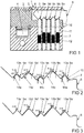
- Figure 1 shows a longitudinal section through a portion of a lock cylinder 1 with a housing 2 and a core 3 rotatably arranged therein. Furthermore, the lock cylinder 1 has a lock bit 4 connected to the core 3 in a rotationally fixed manner. In a lock channel 5 of the core 3 is a key 6 for closing the Lock cylinder 1 introduced.
- the lock cylinder 1 has locking orange 7 designed as pin tumblers to optionally block or release the movement of the core 3.
- the locking orange 7 scan locking recesses 9 arranged in a shaft 8 of the key 6 and each have the same dimensions at their ends facing the locking recesses 9. Furthermore, the locking orange 7 are arranged at the same distance from one another.
- the locking orange 7 each have a core pin 10 guided in the core 3 and a housing pin 11 guided in the housing 2 and a spring element 12 for biasing the housing pin 11 against the core pin 10.
- the parting planes of the housing pins 11 and the core pins 10 of all locking orange 7 are in the parting plane between housing 2 and core 3, so that core 3 can be rotated together with locking bit 4 relative to housing 2.
- Figure 2 shows in a greatly enlarged representation the key 6 with the locking recesses 9a-9e and the locking orange 7 of the lock cylinder 1 in the abutting areas.
- the locking orange 7 each have support surfaces 13a-13e and the core pins 10 are each designed to be frustoconical at their ends for support on the support surfaces 13a-13e.
- the remaining support surfaces 13a-13d are widened by an intended step sequence compared to the standard width and are marked with x + 1 to x + 4.
- the standard width of the support surface 13a with the identification x + 1 is widened by 0.1 mm and the support surface 13b with the identification x + 4 is widened by 0.4 mm.
- the locking element 7 that interacts with the locking recess 9b marked x + 4 Locking element 7 is triggered last in time. In order for the static friction forces of the individual barrier orange 7 are overcome in sequence.
- Figure 3 shows a further embodiment of a key 6 'which extends from the Figure 2 only differs in that the step sequences are designed as a continuous row over the locking recesses 9a'-9e '.
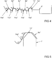
- Figure 4 shows a portion of a further embodiment of the key 6 ′′, which extends from FIG Figure 1 is distinguished by the fact that the flank contours 14a-14e of the closing recesses 9a "-9e" have different angles of inclination A1 to A5 in their areas abutting the free ends of the locking orange 7.
- the angles of inclination A1-A5 increase over the row of closing recesses 9a "-9e” so that the angle of inclination A5 is greater than the angle of inclination A1.
- the locking orange 7 experience different accelerations when removing the key 6 ′′.
- the locking recesses 9a ′′ -9e ′′ of the key 6 ′′ from FIG. 1 can also have support surfaces 13 ′′ of different widths, as in FIG Figures 2 or 3 shown. This would take advantage of the embodiments of the Figures 2, 3 and 4th be connected to each other.
- Figure 5 shows one of the locking recesses 9a ′′ on a greatly enlarged scale Figure 4 with the adjacent area of one of the blocking orange 7. It can be seen here that the flank contour 14a is inconstant, so that the flank contour 14a has the angle of inclination A1 at the lowest point, the angle of inclination B1 in the middle area and the angle of inclination C1 in the flattest area.
Landscapes
- Lock And Its Accessories (AREA)
- Chairs Characterized By Structure (AREA)
Abstract
Description
- Die Erfindung betrifft einen Schlüssel für einen Schließzylinder mit einer Reihe von in einem Schaft angeordneten Schließausnehmungen, wobei die Schließausnehmungen jeweils von Flankenkonturen begrenzt sind und Stützflächen zur Abstützung von Sperrorange des Schließzylinders aufweisen.
- Ein Schließzylinder mit einem Schlüssel ist beispielsweise aus der
WO 2015/114172 A1 bekannt. Der Schließzylinder hat mehrere Sperrorgane, deren Abstände zueinander unterschiedlich sind. Schließausnehmungen im Schlüssel zum Ansteuern der Sperrorgane haben die gleichen Abstände wie die Sperrorgane. Damit soll vermieden werden, dass beim Einführen des Schlüssels in den Schließzylinder die Einführkraft von Sperrorgan zu Sperrorgan zunimmt. - Weiterhin ist aus der
EP 2 281 985 A2 ein Schließzylinder mit einem Schlüssel bekannt geworden, bei dem die Abstände einzelner Sperrorange zueinander variieren. Die Schlüsselbartsteuerkanten zum Ansteuern der Sperrorange weisen dieselben Abstände auf wie Anlageflächen an dem Sperrorange. Dieser Schließzylinder soll ein unberechtigtes Entriegeln mit einer so genannten Picking Methode erschweren. - Aus der
DE 298 18 143 U1 ist ein Schlüssel für einen Schließzylinder bekannt geworden, bei dem Rastvertiefungen zum Ansteuern von Sperrorange des Schließzylinders vorgesehen sind. Die Rastvertiefungen haben Rastflächen zum Abstützen des Sperrorgans. An die Rastflächen angrenzende Übergänge von Schrägflanken haben konkav abgerundete Gleitflächen. Damit soll ein Haken bei der Betätigung des Schließzylinders vermieden werden. - Nachteilig bei den bekannten Schlüsseln ist, dass der Schlüssel im eingeführten Zustand von allen Sperrorange gleichzeitig gehalten ist, da die Sperrorange in der Regel jeweils die gleichen Abmessungen an ihren den Schließausnehmungen zugewandten Enden aufweisen. Dem Abziehen des Schlüssels aus dem Schließzylinder steht wegen des gleichzeitigen Haltens des Schlüssels durch alle Sperrorange eine hohe Abzugskraft entgegen, weil sämtliche Haftreibungen der einzelnen Sperrorange gleichzeitig gelöst werden müssen.
- Der Erfindung liegt das Problem zugrunde, einen Schlüssel der eingangs genannten Art so weiter zu bilden, dass die Abzugskraft bei vollständig in den Schließzylinder eingeführtem Schlüssel möglichst gering gehalten wird.
- Dieses Problem wird erfindungsgemäß dadurch gelöst, dass die Stützflächen einzelner Schließausnehmungen unterschiedliche Breiten aufweisen, wobei die Breiten über die Reihe der Schließausnehmungen zunehmen und/oder dass die Neigungswinkel der Flankenkonturen über die Reihe der Schließausnehmungen zunehmen.
- Damit weisen die Schließausnehmungen nicht mehr die gleiche Breite auf oder haben nicht mehr die gleichen Neigungswinkel der Flankenkonturen, so dass ein gleichzeitiges Ansteuern der Sperrorange von den unterschiedlichen Schließausnehmungen vermieden wird. Vielmehr werden durch die Varianz der Breiten im Schließzylinder die Sperrorange in einer Abfolge bewegt, da die Sperrorange an ihren den Schließausnehmungen zugewandten Enden jeweils dieselben Abmessungen aufweisen. Die Zunahme der Neigungswinkel der Flankenkonturen über die Reihe der Schließausnehmungen hat zur Folge, dass die Sperrorange beim Abziehen des Schlüssels unterschiedliche Beschleunigungen erfahren. Hierdurch wird die Abzugskraft bei vollständig in den Schließzylinder eingeführtem Schlüssel besonders gering gehalten.
- Ein geordnetes Lösen der Sperrorange beim Abziehen des Schlüssels lässt sich gemäß einer anderen vorteilhaften Weiterbildung der Erfindung erzeugen, wenn die Zunahme der Breiten der Schließausnehmungen in einer vorgesehenen Schrittfolge ausgebildet ist. Damit wird beim Abziehen des Schlüssels ein Sperrorgan nach dem anderen gelöst.
- Zur weiteren Vergleichmäßigung der Abzugskraft trägt es gemäß einer anderen vorteilhaften Weiterbildung der Erfindung bei, wenn die Zunahme der Neigungswinkel der Flankenkonturen als stetige Reihe ausgebildet ist.
- Ein langsam ansteigender Kraftverlauf beim Abziehen des Schlüssels lässt sich gemäß einer anderen vorteilhaften Weiterbildung der Erfindung einfach erreichen, wenn die Zunahme der Neigungswinkel in einer vorgesehenen Schrittfolge ausgebildet ist.
- Die Sperrorange lassen sich gemäß einer anderen vorteilhaften Weiterbildung der Erfindung zunächst mit geringem Kraftaufwand lösen und anschließend beschleunigen, wenn die Neigungswinkel der Flankenkonturen unkonstant sind, so dass die Flankenkontur an der tiefsten Stelle der Schließausnehmung einen anderen Neigungswinkel hat als an der flachsten Stelle.
- Eine besonders geringe Abzugskraft lässt sich gemäß einer anderen vorteilhaften Weiterbildung der Erfindung erreichen, wenn sämtliche Breiten der Schließausnehmungen oder die Flankenkonturen sämtlicher Schließausnehmungen über die Reihe der Schließausnehmungen variabel ausgebildet sind.
- Die Fertigung der variabel ausgebildeten Schließausnehmungen gestaltet sich gemäß einer anderen vorteilhaften Weiterbildung der Erfindung besonders kostengünstig, wenn der Schaft im Querschnitt rechteckig gestaltet ist und an seinen Schmalseiten eine Schlüsselbrust und einen Schlüsselrücken hat und wenn die Schließausnehmungen in der Schlüsselbrust angeordnet sind. Hierdurch sind die Schließausnehmung bei der Fertigung von den Breitseiten des Schaftes mittels eines Fräs- oder Schneidwerkzeuges zugänglich und können den Schaft durchdringen. Damit lassen sich die Flankenkonturen besonders einfach mit einer großen Variabilität erzeugen.
- Die Erfindung lässt zahlreiche Ausführungsformen zu. Zur weiteren Verdeutlichung ihres Grundprinzips sind mehrere davon in der Zeichnung dargestellt und werden nachfolgend beschrieben. Diese zeigt in
- Fig. 1
- einen Schließzylinder mit einem darin eingeführten Schlüssel,
- Fig. 2
- vergrößert einen Teilbereich des Schlüssels aus
Figur 1 , - Fig. 3
- eine weitere Ausführungsform des Schlüssels aus
Figur 2 , - Fig. 4
- einen Teilbereich einer weiteren Ausführungsform des Schlüssels,
- Fig. 5
- stark vergrößert einen Teilbereich einer Schließausnehmung des Schlüssels aus
Figur 4 . -
Figur 1 zeigt einen Längsschnitt durch einen Teilbereich eines Schließzylinders 1 mit einem Gehäuse 2 und einem darin drehbar angeordneten Kern 3. Weiterhin hat der Schließzylinder 1 einen mit dem Kern 3 drehfest verbundenen Schließbart 4. In einem Schließkanal 5 des Kerns 3 ist ein Schlüssel 6 zum Schließen des Schließzylinders 1 eingeführt. Der Schließzylinder 1 hat als Stiftzuhaltungen ausgebildete Sperrorange 7 zur wahlweisen Blockierung oder Freigabe der Bewegung des Kerns 3. Die Sperrorange 7 tasten in einem Schaft 8 des Schlüssels 6 angeordnete Schließausnehmungen 9 ab und haben jeweils dieselben Abmessungen an ihren den Schließausnehmungen 9 zugewandten Enden. Weiterhin sind die Sperrorange 7 in demselben Abstand zueinander angeordnet. Die Sperrorange 7 haben jeweils einen in dem Kern 3 geführten Kernstift 10 und einen in dem Gehäuse 2 geführten Gehäusestift 11 und ein Federelement 12 zur Vorspannung des Gehäusestiftes 11 gegen den Kernstift 10. Die Trennebenen der Gehäusestifte 11 und der Kernstifte 10 aller Sperrorange 7 liegen in der Trennebene zwischen Gehäuse 2 und Kern 3, so dass der Kern 3 zusammen mit dem Schließbart 4 gegenüber dem Gehäuse 2 verdreht werden kann. -
Figur 2 zeigt in einer stark vergrößerten Darstellung den Schlüssel 6 mit den Schließausnehmungen 9a - 9e und die Sperrorange 7 des Schließzylinders 1 in den aneinander stoßenden Bereichen. Hierbei ist zu erkennen, dass die Sperrorange 7 jeweils Stützflächen 13a - 13e aufweisen und die Kernstifte 10 jeweils an ihren Enden kegelstumpfförmig zur Abstützung an den Stützflächen 13a - 13e gestaltet sind. Die Stützflächen 13a - 13e weisen unterschiedliche Breiten auf, wobei mit x=0 eine Standardbreite der Stützflächen 13a - 13e festgelegt ist. Eine der Stützflächen 13e hat diese Breite. Die übrigen Stützflächen 13a - 13d sind um eine vorgesehene Schrittfolge gegenüber der Standardbreite verbreitert und mit x+1 bis x+4 gekennzeichnet. Bei einer Schrittfolge von 0,1mm ist die Standardbreite der Stützfläche 13a mit der Kennzeichnung x+1 um 0,1mm verbreitert und die Stützfläche 13b mit der Kennzeichnung x+4 um 0,4mm verbreitert. Beim Abziehen des Schlüssels 6 wird damit zunächst das mit der mit x=0 gekennzeichneten Schließausnehmung 9e zusammenwirkende Sperrorgan 7 angesteuert und erst danach das mit der mit x+1 gekennzeichneten Schließausnehmung 9a zusammenwirkende Sperrorgan 7. Das mit der mit x+4 gekennzeichneten Schließausnehmung 9b zusammenwirkende Sperrorgan 7 wird zeitlich als letztes angesteuert. Damit werden die Haftreibungskräfte der einzelnen Sperrorange 7 der Reihe nach überwunden. -
Figur 3 zeigt eine weitere Ausführungsform eines Schlüssels 6' welcher sich von dem ausFigur 2 nur dadurch unterscheidet, dass die Schrittfolgen als stetige Reihe über die Schließausnehmungen 9a' - 9e' ausgebildet sind. -
Figur 4 zeigt einen Teilbereich einer weiteren Ausführungsform des Schlüssels 6", welcher sich von der ausFigur 1 dadurch unterscheidet, dass Flankenkonturen 14a - 14e der Schließausnehmungen 9a" - 9e" in ihren an die freien Enden der Sperrorange 7 anstoßenden Bereichen unterschiedliche Neigungswinkel A1 bis A5 aufweisen. Die Neigungswinkel A1 - A5 nehmen über die Reihe der Schließausnehmungen 9a" - 9e" zu so dass der Neigungswinkel A5 größer ist als der Neigungswinkel A1. Damit erfahren die Sperrorange 7 beim Abziehen des Schlüssels 6" unterschiedliche Beschleunigungen. - Die Schließausnehmungen 9a" - 9e" des Schlüssels 6" aus Figur können zudem unterschiedlich breite Stützflächen 13" aufweisen, wie in den
Figuren 2 oder 3 dargestellt. Damit würden die Vorteile der Ausführungsformen derFiguren 2, 3 und4 miteinander verbunden werden. -
Figur 5 zeigt stark vergrößert eine der Schließausnehmungen 9a" ausFigur 4 mit dem angrenzenden Bereich einer der Sperrorange 7. Hierbei ist zu erkennen, dass die Flankenkontur 14a unkonstant sind, so dass die Flankenkontur 14a an der tiefsten Stelle den Neigungswinkel A1, im mittleren Bereich den Neigungswinkel B1 und im flachsten Bereich den Neigungswinkel C1 hat.
Claims (7)
- Schlüssel (6) für einen Schließzylinder (1) mit einer Reihe von in einem Schaft (8) angeordneten Schließausnehmungen (9a - 9e), wobei die Schließausnehmungen (9a - 9e) jeweils von Flankenkonturen (14a - 14e) begrenzt sind und Stützflächen (13a - 13e) zur Abstützung von Sperrorganen (7) des Schließzylinders (1) aufweisen, dadurch gekennzeichnet, dass die Stützflächen (13a - 13e) einzelner Schließausnehmungen (9a - 9e) unterschiedliche Breiten aufweisen, wobei die Breiten über die Reihe der Schließausnehmungen (9a - 9e) zunehmen und/oder dass die Neigungswinkel (A1 - A5) der Flankenkonturen (14a - 14e) über die Reihe der Schließausnehmungen (9a" - 9e") zunehmen.
- Schlüssel nach Anspruch 1, dadurch gekennzeichnet, dass die Zunahme der Breiten der Schließausnehmungen (9a - 9e) in einer vorgesehenen Schrittfolge ausgebildet ist.
- Schlüssel nach Anspruch 1 oder 2, dadurch gekennzeichnet, dass die Zunahme der Neigungswinkel (A1 - A5) der Flankenkonturen (14a - 14e) als stetige Reihe ausgebildet ist.
- Schlüssel nach zumindest einem der Ansprüche 1 bis 3, dadurch gekennzeichnet, dass die Zunahme der Neigungswinkel (A1 - A5) in einer vorgesehenen Schrittfolge ausgebildet ist.
- Schlüssel nach zumindest einem der Ansprüche 1 bis 4, dadurch gekennzeichnet, dass die Neigungswinkel (A1, B1, C1) der Flankenkonturen (14a - 14e) unkonstant sind, so dass die Flankenkontur (14a - 14e) an der tiefsten Stelle der Schließausnehmung (9a" - 9e") einen anderen Neigungswinkel (A1, B1, C1) hat als an der flachsten Stelle.
- Schlüssel nach zumindest einem der Ansprüche 1 bis 5, dadurch gekennzeichnet, dass sämtliche Breiten der Schließausnehmungen (9a - 9e) oder die Flankenkonturen (14a - 14e) sämtlicher Schließausnehmungen (9a" - 9e") über die Reihe der Schließausnehmungen (9a - 9e) variabel ausgebildet sind.
- Schlüssel nach zumindest einem der Ansprüche 1 bis 6, dadurch gekennzeichnet, dass der Schaft (8) im Querschnitt rechteckig gestaltet ist und an seinen Schmalseiten eine Schlüsselbrust und einen Schlüsselrücken hat und dass die Schließausnehmungen (9a - 9e) in der Schlüsselbrust angeordnet sind.
Priority Applications (4)
| Application Number | Priority Date | Filing Date | Title |
|---|---|---|---|
| SI202030002T SI3696351T1 (sl) | 2019-02-14 | 2020-01-28 | Ključ za cilindrično ključavnico |
| RS20210822A RS62046B1 (sr) | 2019-02-14 | 2020-01-28 | Ključ za cilindar brave |
| PL20154079T PL3696351T3 (pl) | 2019-02-14 | 2020-01-28 | Klucz do cylindra zamykającego |
| HRP20211039TT HRP20211039T1 (hr) | 2019-02-14 | 2021-06-30 | Ključ za cilindar brave |
Applications Claiming Priority (1)
| Application Number | Priority Date | Filing Date | Title |
|---|---|---|---|
| DE102019201994.3A DE102019201994A1 (de) | 2019-02-14 | 2019-02-14 | SCHLÜSSEL FÜR EINEN SCHLIEßZYLINDER |
Publications (2)
| Publication Number | Publication Date |
|---|---|
| EP3696351A1 true EP3696351A1 (de) | 2020-08-19 |
| EP3696351B1 EP3696351B1 (de) | 2021-04-28 |
Family
ID=69374220
Family Applications (1)
| Application Number | Title | Priority Date | Filing Date |
|---|---|---|---|
| EP20154079.6A Active EP3696351B1 (de) | 2019-02-14 | 2020-01-28 | Schlüssel für einen schliesszylinder |
Country Status (10)
| Country | Link |
|---|---|
| EP (1) | EP3696351B1 (de) |
| DE (1) | DE102019201994A1 (de) |
| DK (1) | DK3696351T3 (de) |
| ES (1) | ES2872324T3 (de) |
| HR (1) | HRP20211039T1 (de) |
| HU (1) | HUE054734T2 (de) |
| PL (1) | PL3696351T3 (de) |
| PT (1) | PT3696351T (de) |
| RS (1) | RS62046B1 (de) |
| SI (1) | SI3696351T1 (de) |
Citations (7)
| Publication number | Priority date | Publication date | Assignee | Title |
|---|---|---|---|---|
| GB1284914A (en) * | 1968-12-11 | 1972-08-09 | Eaton Gmbh | Improvements in or relating to keys for cylinder locks |
| WO1999051837A1 (de) * | 1998-04-04 | 1999-10-14 | Evva-Werk Spezialerzeugung Von Zylinder- Und Sicherheitsschlössern Gesellschaft Mbh & Co. Kommanditgesellschaft | Flachschlüssel und zylinderschloss |
| DE29818143U1 (de) | 1998-10-10 | 2000-02-17 | Bks Gmbh, 42549 Velbert | Sicherheitsschlüssel |
| DE102004009166A1 (de) * | 2004-02-25 | 2005-10-06 | Aug. Winkhaus Gmbh & Co. Kg | Schlüssel für einen Schließzylinder |
| EP2281985A2 (de) | 2009-08-06 | 2011-02-09 | EVVA Sicherheitstechnologie GmbH | Schlüssel und Zylinderschloss |
| WO2015114172A1 (de) | 2014-02-03 | 2015-08-06 | Huf Hülsbeck & Fürst Gmbh & Co. Kg | SCHLIEßZYLINDER FÜR EINE SCHLOSSVORRICHTUNG |
| WO2018188971A1 (de) * | 2017-04-11 | 2018-10-18 | Evva Sicherheitstechnologie Gmbh | Schlüssel und zylinderschloss |
-
2019
- 2019-02-14 DE DE102019201994.3A patent/DE102019201994A1/de not_active Withdrawn
-
2020
- 2020-01-28 RS RS20210822A patent/RS62046B1/sr unknown
- 2020-01-28 PT PT201540796T patent/PT3696351T/pt unknown
- 2020-01-28 PL PL20154079T patent/PL3696351T3/pl unknown
- 2020-01-28 DK DK20154079.6T patent/DK3696351T3/da active
- 2020-01-28 EP EP20154079.6A patent/EP3696351B1/de active Active
- 2020-01-28 ES ES20154079T patent/ES2872324T3/es active Active
- 2020-01-28 SI SI202030002T patent/SI3696351T1/sl unknown
- 2020-01-28 HU HUE20154079A patent/HUE054734T2/hu unknown
-
2021
- 2021-06-30 HR HRP20211039TT patent/HRP20211039T1/hr unknown
Patent Citations (7)
| Publication number | Priority date | Publication date | Assignee | Title |
|---|---|---|---|---|
| GB1284914A (en) * | 1968-12-11 | 1972-08-09 | Eaton Gmbh | Improvements in or relating to keys for cylinder locks |
| WO1999051837A1 (de) * | 1998-04-04 | 1999-10-14 | Evva-Werk Spezialerzeugung Von Zylinder- Und Sicherheitsschlössern Gesellschaft Mbh & Co. Kommanditgesellschaft | Flachschlüssel und zylinderschloss |
| DE29818143U1 (de) | 1998-10-10 | 2000-02-17 | Bks Gmbh, 42549 Velbert | Sicherheitsschlüssel |
| DE102004009166A1 (de) * | 2004-02-25 | 2005-10-06 | Aug. Winkhaus Gmbh & Co. Kg | Schlüssel für einen Schließzylinder |
| EP2281985A2 (de) | 2009-08-06 | 2011-02-09 | EVVA Sicherheitstechnologie GmbH | Schlüssel und Zylinderschloss |
| WO2015114172A1 (de) | 2014-02-03 | 2015-08-06 | Huf Hülsbeck & Fürst Gmbh & Co. Kg | SCHLIEßZYLINDER FÜR EINE SCHLOSSVORRICHTUNG |
| WO2018188971A1 (de) * | 2017-04-11 | 2018-10-18 | Evva Sicherheitstechnologie Gmbh | Schlüssel und zylinderschloss |
Also Published As
| Publication number | Publication date |
|---|---|
| DE102019201994A1 (de) | 2020-08-20 |
| HRP20211039T1 (hr) | 2021-10-01 |
| SI3696351T1 (sl) | 2021-08-31 |
| ES2872324T3 (es) | 2021-11-02 |
| DK3696351T3 (da) | 2021-07-05 |
| PT3696351T (pt) | 2021-06-01 |
| RS62046B1 (sr) | 2021-07-30 |
| HUE054734T2 (hu) | 2021-09-28 |
| EP3696351B1 (de) | 2021-04-28 |
| PL3696351T3 (pl) | 2021-10-18 |
Similar Documents
| Publication | Publication Date | Title |
|---|---|---|
| DE69005060T2 (de) | Zylinderschloss und Schlüssel. | |
| EP1607553B1 (de) | Schliesszylinder | |
| DE102014108355A1 (de) | Zylinderschloss | |
| EP3696351B1 (de) | Schlüssel für einen schliesszylinder | |
| DE69508374T2 (de) | Schlüssel und Zylinderschlossanlage | |
| EP3696352B1 (de) | Schlüssel für einen schliesszylinder | |
| EP3696353A1 (de) | Schliesseinrichtung mit einem schlüssel und einem schliesszylinder | |
| DE20105519U1 (de) | Zylinderschloß mit Zylindergehäuse und Flachschlüssel für ein Zylinderschloß | |
| EP1577469B1 (de) | Schlüssel | |
| EP2221436A2 (de) | Schlüssel für einen Schließzylinder | |
| EP4379173B1 (de) | Schliesszylinder | |
| EP2149657B1 (de) | Schlüssel für einen Schließzylinder und Rohling für einen solchen Schlüssel | |
| EP1464778B1 (de) | Schliesszylinder | |
| DE202006003869U1 (de) | Zylinderschloss und Flachschlüssel | |
| EP4139545B1 (de) | Schliesssystem mit einem zylinderschloss und einem flachschlüssel | |
| DE2442681A1 (de) | Abtastsicheres drehzylinderschloss | |
| EP3412849B1 (de) | Schlüssel für einen schliesszylinder und schliesszylinder für einen solchen schlüssel | |
| EP1746226A2 (de) | Schlüssel und Schließzylinder für einen Schlüssel | |
| DE185313C (de) | ||
| DE60209547T2 (de) | Verriegelungsvorrichtungs-sicherheitsschloss | |
| EP3095931B1 (de) | Schliesszylinder und schliesssystem mit einem solchen schliesszylinder | |
| DE2800539A1 (de) | Zuhaltungsschloss | |
| AT511401B1 (de) | Zylinderschloss mit mehrteiligem gehäusestift | |
| DE102007056739A1 (de) | Plättchenzylinderschloss | |
| DE29507953U1 (de) | Flachschlüssel und Zylinderschloß |
Legal Events
| Date | Code | Title | Description |
|---|---|---|---|
| PUAI | Public reference made under article 153(3) epc to a published international application that has entered the european phase |
Free format text: ORIGINAL CODE: 0009012 |
|
| STAA | Information on the status of an ep patent application or granted ep patent |
Free format text: STATUS: THE APPLICATION HAS BEEN PUBLISHED |
|
| AK | Designated contracting states |
Kind code of ref document: A1 Designated state(s): AL AT BE BG CH CY CZ DE DK EE ES FI FR GB GR HR HU IE IS IT LI LT LU LV MC MK MT NL NO PL PT RO RS SE SI SK SM TR |
|
| AX | Request for extension of the european patent |
Extension state: BA ME |
|
| STAA | Information on the status of an ep patent application or granted ep patent |
Free format text: STATUS: REQUEST FOR EXAMINATION WAS MADE |
|
| 17P | Request for examination filed |
Effective date: 20201001 |
|
| RBV | Designated contracting states (corrected) |
Designated state(s): AL AT BE BG CH CY CZ DE DK EE ES FI FR GB GR HR HU IE IS IT LI LT LU LV MC MK MT NL NO PL PT RO RS SE SI SK SM TR |
|
| GRAP | Despatch of communication of intention to grant a patent |
Free format text: ORIGINAL CODE: EPIDOSNIGR1 |
|
| STAA | Information on the status of an ep patent application or granted ep patent |
Free format text: STATUS: GRANT OF PATENT IS INTENDED |
|
| INTG | Intention to grant announced |
Effective date: 20210113 |
|
| GRAS | Grant fee paid |
Free format text: ORIGINAL CODE: EPIDOSNIGR3 |
|
| GRAA | (expected) grant |
Free format text: ORIGINAL CODE: 0009210 |
|
| STAA | Information on the status of an ep patent application or granted ep patent |
Free format text: STATUS: THE PATENT HAS BEEN GRANTED |
|
| AK | Designated contracting states |
Kind code of ref document: B1 Designated state(s): AL AT BE BG CH CY CZ DE DK EE ES FI FR GB GR HR HU IE IS IT LI LT LU LV MC MK MT NL NO PL PT RO RS SE SI SK SM TR |
|
| REG | Reference to a national code |
Ref country code: GB Ref legal event code: FG4D Free format text: NOT ENGLISH |
|
| REG | Reference to a national code |
Ref country code: CH Ref legal event code: EP |
|
| REG | Reference to a national code |
Ref country code: DE Ref legal event code: R096 Ref document number: 502020000032 Country of ref document: DE |
|
| REG | Reference to a national code |
Ref country code: CH Ref legal event code: NV Representative=s name: VALIPAT S.A. C/O BOVARD SA NEUCHATEL, CH |
|
| REG | Reference to a national code |
Ref country code: AT Ref legal event code: REF Ref document number: 1387205 Country of ref document: AT Kind code of ref document: T Effective date: 20210515 |
|
| REG | Reference to a national code |
Ref country code: IE Ref legal event code: FG4D Free format text: LANGUAGE OF EP DOCUMENT: GERMAN |
|
| REG | Reference to a national code |
Ref country code: PT Ref legal event code: SC4A Ref document number: 3696351 Country of ref document: PT Date of ref document: 20210601 Kind code of ref document: T Free format text: AVAILABILITY OF NATIONAL TRANSLATION Effective date: 20210511 |
|
| REG | Reference to a national code |
Ref country code: RO Ref legal event code: EPE |
|
| REG | Reference to a national code |
Ref country code: HR Ref legal event code: TUEP Ref document number: P20211039T Country of ref document: HR Ref country code: FI Ref legal event code: FGE |
|
| REG | Reference to a national code |
Ref country code: DK Ref legal event code: T3 Effective date: 20210701 |
|
| REG | Reference to a national code |
Ref country code: SK Ref legal event code: T3 Ref document number: E 37222 Country of ref document: SK Ref country code: NL Ref legal event code: FP |
|
| REG | Reference to a national code |
Ref country code: SE Ref legal event code: TRGR |
|
| REG | Reference to a national code |
Ref country code: GR Ref legal event code: EP Ref document number: 20210401588 Country of ref document: GR Effective date: 20210709 |
|
| REG | Reference to a national code |
Ref country code: LT Ref legal event code: MG9D |
|
| REG | Reference to a national code |
Ref country code: HU Ref legal event code: AG4A Ref document number: E054734 Country of ref document: HU |
|
| REG | Reference to a national code |
Ref country code: HR Ref legal event code: T1PR Ref document number: P20211039 Country of ref document: HR |
|
| PG25 | Lapsed in a contracting state [announced via postgrant information from national office to epo] |
Ref country code: LT Free format text: LAPSE BECAUSE OF FAILURE TO SUBMIT A TRANSLATION OF THE DESCRIPTION OR TO PAY THE FEE WITHIN THE PRESCRIBED TIME-LIMIT Effective date: 20210428 |
|
| REG | Reference to a national code |
Ref country code: ES Ref legal event code: FG2A Ref document number: 2872324 Country of ref document: ES Kind code of ref document: T3 Effective date: 20211102 |
|
| PG25 | Lapsed in a contracting state [announced via postgrant information from national office to epo] |
Ref country code: IS Free format text: LAPSE BECAUSE OF FAILURE TO SUBMIT A TRANSLATION OF THE DESCRIPTION OR TO PAY THE FEE WITHIN THE PRESCRIBED TIME-LIMIT Effective date: 20210828 Ref country code: LV Free format text: LAPSE BECAUSE OF FAILURE TO SUBMIT A TRANSLATION OF THE DESCRIPTION OR TO PAY THE FEE WITHIN THE PRESCRIBED TIME-LIMIT Effective date: 20210428 Ref country code: NO Free format text: LAPSE BECAUSE OF FAILURE TO SUBMIT A TRANSLATION OF THE DESCRIPTION OR TO PAY THE FEE WITHIN THE PRESCRIBED TIME-LIMIT Effective date: 20210728 |
|
| PG25 | Lapsed in a contracting state [announced via postgrant information from national office to epo] |
Ref country code: EE Free format text: LAPSE BECAUSE OF FAILURE TO SUBMIT A TRANSLATION OF THE DESCRIPTION OR TO PAY THE FEE WITHIN THE PRESCRIBED TIME-LIMIT Effective date: 20210428 Ref country code: SM Free format text: LAPSE BECAUSE OF FAILURE TO SUBMIT A TRANSLATION OF THE DESCRIPTION OR TO PAY THE FEE WITHIN THE PRESCRIBED TIME-LIMIT Effective date: 20210428 |
|
| REG | Reference to a national code |
Ref country code: DE Ref legal event code: R097 Ref document number: 502020000032 Country of ref document: DE |
|
| REG | Reference to a national code |
Ref country code: HR Ref legal event code: ODRP Ref document number: P20211039 Country of ref document: HR Payment date: 20220118 Year of fee payment: 3 |
|
| PLBE | No opposition filed within time limit |
Free format text: ORIGINAL CODE: 0009261 |
|
| STAA | Information on the status of an ep patent application or granted ep patent |
Free format text: STATUS: NO OPPOSITION FILED WITHIN TIME LIMIT |
|
| 26N | No opposition filed |
Effective date: 20220131 |
|
| PG25 | Lapsed in a contracting state [announced via postgrant information from national office to epo] |
Ref country code: IS Free format text: LAPSE BECAUSE OF FAILURE TO SUBMIT A TRANSLATION OF THE DESCRIPTION OR TO PAY THE FEE WITHIN THE PRESCRIBED TIME-LIMIT Effective date: 20210828 Ref country code: AL Free format text: LAPSE BECAUSE OF FAILURE TO SUBMIT A TRANSLATION OF THE DESCRIPTION OR TO PAY THE FEE WITHIN THE PRESCRIBED TIME-LIMIT Effective date: 20210428 |
|
| PG25 | Lapsed in a contracting state [announced via postgrant information from national office to epo] |
Ref country code: MC Free format text: LAPSE BECAUSE OF FAILURE TO SUBMIT A TRANSLATION OF THE DESCRIPTION OR TO PAY THE FEE WITHIN THE PRESCRIBED TIME-LIMIT Effective date: 20210428 |
|
| PG25 | Lapsed in a contracting state [announced via postgrant information from national office to epo] |
Ref country code: IE Free format text: LAPSE BECAUSE OF NON-PAYMENT OF DUE FEES Effective date: 20220128 |
|
| REG | Reference to a national code |
Ref country code: HR Ref legal event code: ODRP Ref document number: P20211039 Country of ref document: HR Payment date: 20230117 Year of fee payment: 4 |
|
| P01 | Opt-out of the competence of the unified patent court (upc) registered |
Effective date: 20230515 |
|
| REG | Reference to a national code |
Ref country code: HR Ref legal event code: ODRP Ref document number: P20211039 Country of ref document: HR Payment date: 20240119 Year of fee payment: 5 |
|
| PG25 | Lapsed in a contracting state [announced via postgrant information from national office to epo] |
Ref country code: CY Free format text: LAPSE BECAUSE OF FAILURE TO SUBMIT A TRANSLATION OF THE DESCRIPTION OR TO PAY THE FEE WITHIN THE PRESCRIBED TIME-LIMIT Effective date: 20210428 |
|
| PG25 | Lapsed in a contracting state [announced via postgrant information from national office to epo] |
Ref country code: MT Free format text: LAPSE BECAUSE OF FAILURE TO SUBMIT A TRANSLATION OF THE DESCRIPTION OR TO PAY THE FEE WITHIN THE PRESCRIBED TIME-LIMIT Effective date: 20210428 |
|
| REG | Reference to a national code |
Ref country code: DE Ref legal event code: R081 Ref document number: 502020000032 Country of ref document: DE Owner name: AUG. WINKHAUS SE & CO. KG, DE Free format text: FORMER OWNER: AUG. WINKHAUS GMBH & CO. KG, 48291 TELGTE, DE Ref country code: DE Ref legal event code: R081 Ref document number: 502020000032 Country of ref document: DE Owner name: AUG. WINKHAUS SE, DE Free format text: FORMER OWNER: AUG. WINKHAUS GMBH & CO. KG, 48291 TELGTE, DE |
|
| REG | Reference to a national code |
Ref country code: HR Ref legal event code: ODRP Ref document number: P20211039 Country of ref document: HR Payment date: 20250122 Year of fee payment: 6 |
|
| PGFP | Annual fee paid to national office [announced via postgrant information from national office to epo] |
Ref country code: BG Payment date: 20250121 Year of fee payment: 6 |
|
| PGFP | Annual fee paid to national office [announced via postgrant information from national office to epo] |
Ref country code: SI Payment date: 20250120 Year of fee payment: 6 |
|
| REG | Reference to a national code |
Ref country code: DE Ref legal event code: R081 Ref document number: 502020000032 Country of ref document: DE Owner name: AUG. WINKHAUS SE, DE Free format text: FORMER OWNER: AUG. WINKHAUS SE & CO. KG, 48291 TELGTE, DE |
|
| PGFP | Annual fee paid to national office [announced via postgrant information from national office to epo] |
Ref country code: MK Payment date: 20250116 Year of fee payment: 6 |
|
| REG | Reference to a national code |
Ref country code: CH Ref legal event code: U11 Free format text: ST27 STATUS EVENT CODE: U-0-0-U10-U11 (AS PROVIDED BY THE NATIONAL OFFICE) Effective date: 20260201 |
|
| REG | Reference to a national code |
Ref country code: HR Ref legal event code: ODRP Ref document number: P20211039 Country of ref document: HR Payment date: 20260120 Year of fee payment: 7 |
|
| PGFP | Annual fee paid to national office [announced via postgrant information from national office to epo] |
Ref country code: LU Payment date: 20260121 Year of fee payment: 7 Ref country code: NL Payment date: 20260121 Year of fee payment: 7 |
|
| PGFP | Annual fee paid to national office [announced via postgrant information from national office to epo] |
Ref country code: HU Payment date: 20260126 Year of fee payment: 7 |
|
| PGFP | Annual fee paid to national office [announced via postgrant information from national office to epo] |
Ref country code: SE Payment date: 20260121 Year of fee payment: 7 |
|
| PGFP | Annual fee paid to national office [announced via postgrant information from national office to epo] |
Ref country code: GB Payment date: 20260122 Year of fee payment: 7 |
|
| PGFP | Annual fee paid to national office [announced via postgrant information from national office to epo] |
Ref country code: ES Payment date: 20260217 Year of fee payment: 7 |
|
| PGFP | Annual fee paid to national office [announced via postgrant information from national office to epo] |
Ref country code: DK Payment date: 20260115 Year of fee payment: 7 Ref country code: DE Payment date: 20260120 Year of fee payment: 7 |
|
| PGFP | Annual fee paid to national office [announced via postgrant information from national office to epo] |
Ref country code: AT Payment date: 20260119 Year of fee payment: 7 Ref country code: HR Payment date: 20260120 Year of fee payment: 7 |
|
| PGFP | Annual fee paid to national office [announced via postgrant information from national office to epo] |
Ref country code: BE Payment date: 20260121 Year of fee payment: 7 Ref country code: RO Payment date: 20260122 Year of fee payment: 7 Ref country code: FI Payment date: 20260120 Year of fee payment: 7 Ref country code: IT Payment date: 20260130 Year of fee payment: 7 |
|
| PGFP | Annual fee paid to national office [announced via postgrant information from national office to epo] |
Ref country code: RS Payment date: 20260116 Year of fee payment: 7 |
|
| PGFP | Annual fee paid to national office [announced via postgrant information from national office to epo] |
Ref country code: FR Payment date: 20260128 Year of fee payment: 7 |
|
| PGFP | Annual fee paid to national office [announced via postgrant information from national office to epo] |
Ref country code: TR Payment date: 20260126 Year of fee payment: 7 |
|
| PGFP | Annual fee paid to national office [announced via postgrant information from national office to epo] |
Ref country code: PT Payment date: 20260120 Year of fee payment: 7 Ref country code: CZ Payment date: 20260115 Year of fee payment: 7 Ref country code: CH Payment date: 20260201 Year of fee payment: 7 |
|
| PGFP | Annual fee paid to national office [announced via postgrant information from national office to epo] |
Ref country code: GR Payment date: 20260119 Year of fee payment: 7 Ref country code: PL Payment date: 20260119 Year of fee payment: 7 |
|
| PGFP | Annual fee paid to national office [announced via postgrant information from national office to epo] |
Ref country code: SK Payment date: 20260122 Year of fee payment: 7 |