EP3696014A1 - Ensemble support de coussin de siège de véhicule pour siège de véhicule modulaire ou similaire - Google Patents
Ensemble support de coussin de siège de véhicule pour siège de véhicule modulaire ou similaire Download PDFInfo
- Publication number
- EP3696014A1 EP3696014A1 EP20153374.2A EP20153374A EP3696014A1 EP 3696014 A1 EP3696014 A1 EP 3696014A1 EP 20153374 A EP20153374 A EP 20153374A EP 3696014 A1 EP3696014 A1 EP 3696014A1
- Authority
- EP
- European Patent Office
- Prior art keywords
- seat
- upholstery
- seat cushion
- cushion carrier
- cushion
- Prior art date
- Legal status (The legal status is an assumption and is not a legal conclusion. Google has not performed a legal analysis and makes no representation as to the accuracy of the status listed.)
- Granted
Links
- 239000000463 material Substances 0.000 claims description 47
- 239000011324 bead Substances 0.000 claims description 10
- 230000014759 maintenance of location Effects 0.000 claims description 9
- 230000000717 retained effect Effects 0.000 claims description 8
- 239000006260 foam Substances 0.000 abstract description 28
- 230000000712 assembly Effects 0.000 abstract description 15
- 238000000429 assembly Methods 0.000 abstract description 15
- 238000007373 indentation Methods 0.000 abstract description 7
- 230000007246 mechanism Effects 0.000 description 18
- 238000000034 method Methods 0.000 description 7
- 238000010586 diagram Methods 0.000 description 6
- 230000008569 process Effects 0.000 description 5
- 230000004308 accommodation Effects 0.000 description 3
- 238000004519 manufacturing process Methods 0.000 description 3
- 239000002184 metal Substances 0.000 description 3
- 238000009423 ventilation Methods 0.000 description 3
- 230000008878 coupling Effects 0.000 description 2
- 238000010168 coupling process Methods 0.000 description 2
- 238000005859 coupling reaction Methods 0.000 description 2
- 238000001514 detection method Methods 0.000 description 2
- 239000004744 fabric Substances 0.000 description 2
- 238000010438 heat treatment Methods 0.000 description 2
- 239000010985 leather Substances 0.000 description 2
- 229910001092 metal group alloy Inorganic materials 0.000 description 2
- 229920002994 synthetic fiber Polymers 0.000 description 2
- 230000008901 benefit Effects 0.000 description 1
- 238000001816 cooling Methods 0.000 description 1
- 230000001419 dependent effect Effects 0.000 description 1
- 238000005516 engineering process Methods 0.000 description 1
- 230000002708 enhancing effect Effects 0.000 description 1
- 230000006870 function Effects 0.000 description 1
- 230000003993 interaction Effects 0.000 description 1
- 230000002452 interceptive effect Effects 0.000 description 1
- 230000008439 repair process Effects 0.000 description 1
Images


Classifications
-
- B—PERFORMING OPERATIONS; TRANSPORTING
- B60—VEHICLES IN GENERAL
- B60N—SEATS SPECIALLY ADAPTED FOR VEHICLES; VEHICLE PASSENGER ACCOMMODATION NOT OTHERWISE PROVIDED FOR
- B60N2/00—Seats specially adapted for vehicles; Arrangement or mounting of seats in vehicles
- B60N2/70—Upholstery springs ; Upholstery
- B60N2/72—Attachment or adjustment thereof
-
- B—PERFORMING OPERATIONS; TRANSPORTING
- B60—VEHICLES IN GENERAL
- B60N—SEATS SPECIALLY ADAPTED FOR VEHICLES; VEHICLE PASSENGER ACCOMMODATION NOT OTHERWISE PROVIDED FOR
- B60N2/00—Seats specially adapted for vehicles; Arrangement or mounting of seats in vehicles
- B60N2/64—Back-rests or cushions
-
- A—HUMAN NECESSITIES
- A47—FURNITURE; DOMESTIC ARTICLES OR APPLIANCES; COFFEE MILLS; SPICE MILLS; SUCTION CLEANERS IN GENERAL
- A47C—CHAIRS; SOFAS; BEDS
- A47C31/00—Details or accessories for chairs, beds, or the like, not provided for in other groups of this subclass, e.g. upholstery fasteners, mattress protectors, stretching devices for mattress nets
- A47C31/02—Upholstery attaching means
- A47C31/023—Upholstery attaching means connecting upholstery to frames, e.g. by hooks, clips, snap fasteners, clamping means or the like
-
- B—PERFORMING OPERATIONS; TRANSPORTING
- B60—VEHICLES IN GENERAL
- B60N—SEATS SPECIALLY ADAPTED FOR VEHICLES; VEHICLE PASSENGER ACCOMMODATION NOT OTHERWISE PROVIDED FOR
- B60N2/00—Seats specially adapted for vehicles; Arrangement or mounting of seats in vehicles
- B60N2/58—Seat coverings
- B60N2/5816—Seat coverings attachments thereof
- B60N2/5825—Seat coverings attachments thereof by hooks, staples, clips, snap fasteners or the like
-
- B—PERFORMING OPERATIONS; TRANSPORTING
- B60—VEHICLES IN GENERAL
- B60N—SEATS SPECIALLY ADAPTED FOR VEHICLES; VEHICLE PASSENGER ACCOMMODATION NOT OTHERWISE PROVIDED FOR
- B60N2/00—Seats specially adapted for vehicles; Arrangement or mounting of seats in vehicles
- B60N2/58—Seat coverings
- B60N2/5816—Seat coverings attachments thereof
- B60N2/5841—Seat coverings attachments thereof by clamping means
-
- B—PERFORMING OPERATIONS; TRANSPORTING
- B60—VEHICLES IN GENERAL
- B60N—SEATS SPECIALLY ADAPTED FOR VEHICLES; VEHICLE PASSENGER ACCOMMODATION NOT OTHERWISE PROVIDED FOR
- B60N2/00—Seats specially adapted for vehicles; Arrangement or mounting of seats in vehicles
- B60N2/58—Seat coverings
- B60N2/5816—Seat coverings attachments thereof
- B60N2/585—Seat coverings attachments thereof by buckle passages
-
- B—PERFORMING OPERATIONS; TRANSPORTING
- B60—VEHICLES IN GENERAL
- B60N—SEATS SPECIALLY ADAPTED FOR VEHICLES; VEHICLE PASSENGER ACCOMMODATION NOT OTHERWISE PROVIDED FOR
- B60N2/00—Seats specially adapted for vehicles; Arrangement or mounting of seats in vehicles
- B60N2/62—Thigh-rests
-
- B—PERFORMING OPERATIONS; TRANSPORTING
- B60—VEHICLES IN GENERAL
- B60N—SEATS SPECIALLY ADAPTED FOR VEHICLES; VEHICLE PASSENGER ACCOMMODATION NOT OTHERWISE PROVIDED FOR
- B60N2/00—Seats specially adapted for vehicles; Arrangement or mounting of seats in vehicles
- B60N2/68—Seat frames
-
- B—PERFORMING OPERATIONS; TRANSPORTING
- B60—VEHICLES IN GENERAL
- B60N—SEATS SPECIALLY ADAPTED FOR VEHICLES; VEHICLE PASSENGER ACCOMMODATION NOT OTHERWISE PROVIDED FOR
- B60N2/00—Seats specially adapted for vehicles; Arrangement or mounting of seats in vehicles
- B60N2/70—Upholstery springs ; Upholstery
-
- B—PERFORMING OPERATIONS; TRANSPORTING
- B60—VEHICLES IN GENERAL
- B60N—SEATS SPECIALLY ADAPTED FOR VEHICLES; VEHICLE PASSENGER ACCOMMODATION NOT OTHERWISE PROVIDED FOR
- B60N2/00—Seats specially adapted for vehicles; Arrangement or mounting of seats in vehicles
- B60N2/90—Details or parts not otherwise provided for
- B60N2/919—Positioning and locking mechanisms
Definitions
- the present invention relates generally to the automotive and vehicle seat fields. More specifically, the present invention relates to a vehicle seat cushion carrier assembly for a modular vehicle seat or the like. Such modular vehicle seats find applicability in both traditional and autonomous driving (AD) applications.
- AD autonomous driving
- front buckets seats, a rear bench seat, optionally rear bucket seats, and optionally third row seats must typically be designed and developed, with different adjustment and comfort features built into each.
- different front bucket seats, a different rear bench seat, optionally different rear bucket seats, and optionally different third row seats must typically be designed and developed, again with different adjustment and comfort features built into each. This is expensive and time consuming, especially as autonomous driving (AD) vehicles and the like with both front and rear facing seat configurations become a reality.
- AD autonomous driving
- a seat when installed in a vehicle, it is often partially or wholly assembled in or near the vehicle.
- functional convenience and comfort units such as heating pads, ventilation fans, massage units, etc.
- trim pieces are coupled to the seat frame, along with a cushion foam.
- the cushion foam is upholstered using hog rings or the like.
- Hog rings are basically staples that secure the upholstery to/around the cushion foam, or wires disposed within or adjacent to the cushion foam, creating appropriate seams, creases, and indentations, such that a finished appearance is provided.
- the present invention provides such an improved vehicle seat cushion carrier assembly (bottom and back) via which a cushion carrier structure, cushion foam, and upholstery are more easily assembled and installed in a vehicle, optionally as a modular unit.
- the cushion carrier structure can be multi-piece and incorporate any desired trim units.
- the cushion carrier structure also has a design and configuration that allows the cushion carrier structure to be readily and securely coupled to the underlying seat pan and/or seat frame. Strap fasteners are used to secure the upholstery to the cushion carrier structure and cushion foam, creating the desired creating seams, creases, and indentations. This replaces the use of difficult and time consuming hog rings and the like.
- Clip fasteners are used to secure the upholstery to the cushion carrier structure around the cushion foam, replacing mechanisms that secure the upholstery to the seat frame, especially with respect to the seat back. This allows much of the upholstering to be done outside the vehicle, optionally in a modular manner. Finally, these modular features and functionalities allow the cushion carrier assemblies (bottom and back) to be quickly and easily secured to the underlying seat pan and/or seat frame using simple screws, hooks, and clip fasteners.
- the vehicle seat cushion carrier assembly includes: a seat cushion carrier structure adapted to be selectively coupled to seat frame of a vehicle seat; a seat cushion coupled to the seat cushion carrier structure; and an upholstery material disposed about the seat cushion and secured to the seat cushion carrier structure using one or more of a plurality of strap fasteners and a plurality of clip fasteners. Selected ones of the plurality of strap fasteners are coupled to an underside of the upholstery material, pass completely through the seat cushion, and are secured to one of an underside and a backside of the seat cushion carrier structure.
- Each of the plurality of strap fasteners includes a strap root adapted to be selectively coupled to the underside of the upholstery material and an adjoining elongate member adapted to be disposed completely through the seat cushion and engage a locking boss coupled to the backside of the seat cushion carrier structure.
- the strap root defines a retention channel adapted to selectively engage and retain one or more of a bead structure joined to the underside of the upholstery material and a seam manufactured into the underside of the upholstery material.
- the elongate member defines one or more holes adapted to selectively engage and be retained by the locking boss coupled to the backside of the seat cushion carrier structure.
- the elongate member is manufactured from a flexible material.
- Each of the plurality of clip fasteners includes a rail clip attached to an edge of the upholstery material and disposed about an edge of the seat cushion carrier structure.
- the vehicle seat upholstery strap fastener provided herein includes: a strap root adapted to be selectively coupled to an underside of an upholstery material; and an elongate member coupled to the strap root and adapted to be disposed completely through a seat cushion and engage a locking boss coupled to a backside of a seat cushion carrier structure adjacent to which the seat cushion is disposed.
- the strap root and the elongate member are integrally formed.
- the strap root defines a retention channel adapted to selectively engage and retain one or more of a bead structure joined to the underside of the upholstery material and a seam manufactured into the underside of the upholstery material.
- the elongate member defines one or more holes adapted to selectively engage and be retained by the locking boss coupled to the backside of the seat cushion carrier structure.
- the elongate member is manufactured from a flexible material.
- the elongate member also defines a channel adapted to selectively engage and be guided by a guide boss coupled to the backside of the seat cushion carrier structure.
- the elongate member is adapted to selectively engage and be guided by a guide recess structure disposed one of in and on the backside of the seat cushion carrier structure.
- the elongate member includes a tapered tip portion opposite the strap root.
- the elongate member includes one or more friction gripping structures disposed on an exterior surface thereof.
- the vehicle seat provided herein is assembled by a process including: coupling a modular seat cushion carrier assembly to a seat frame of the vehicle seat, wherein the modular seat cushion carrier assembly includes: a seat cushion carrier structure adapted to be selectively coupled to the seat frame of the vehicle seat; a seat cushion coupled to the seat cushion carrier structure; and an upholstery material disposed about the seat cushion and secured to the seat cushion carrier structure using one or more of a plurality of strap fasteners and a plurality of clip fasteners. Selected ones of the plurality of strap fasteners are coupled to an underside of the upholstery material, pass completely through the seat cushion, and are secured to one of an underside and a backside of the seat cushion carrier structure.
- Each of the plurality of strap fasteners includes a strap root adapted to be selectively coupled to the underside of the upholstery material and an adjoining elongate member adapted to be disposed completely through the seat cushion and engage a locking boss coupled to the backside of the seat cushion carrier structure.
- the strap root defines a retention channel adapted to selectively engage and retain one or more of a bead structure joined to the underside of the upholstery material and a seam manufactured into the underside of the upholstery material.
- the elongate member defines one or more holes adapted to selectively engage and be retained by the locking boss coupled to the backside of the seat cushion carrier structure.
- the elongate member is manufactured from a flexible material.
- Each of the plurality of clip fasteners includes a rail clip attached to an edge of the upholstery material and disposed about an edge of the seat cushion carrier structure.
- the invention provides a vehicle seat cushion carrier assembly, comprising:
- selected ones of the plurality of strap fasteners are coupled to an underside of the upholstery material, pass completely through the seat cushion, and are secured to one of an underside and a backside of the seat cushion carrier structure.
- each of the plurality of strap fasteners comprises a strap root adapted to be selectively coupled to the underside of the upholstery material and an adjoining elongate member adapted to be disposed completely through the seat cushion and engage a locking boss coupled to the backside of the seat cushion carrier structure.
- the strap root defines a retention channel adapted to selectively engage and retain one or more of a bead structure joined to the underside of the upholstery material and a seam manufactured into the underside of the upholstery material, and/or wherein the elongate member defines one or more holes adapted to selectively engage and be retained by the locking boss coupled to the backside of the seat cushion carrier structure.
- the elongate member is manufactured from a flexible material.
- each of the plurality of clip fasteners comprises a rail clip attached to an edge of the upholstery material and disposed about an edge of the seat cushion carrier structure.
- the invention provides a vehicle seat upholstery strap fastener, comprising:
- the strap root and the elongate member are integrally formed.
- the strap root defines a retention channel adapted to selectively engage and retain one or more of a bead structure joined to the underside of the upholstery material and a seam manufactured into the underside of the upholstery material.
- the elongate member defines one or more holes adapted to selectively engage and be retained by the locking boss coupled to the backside of the seat cushion carrier structure.
- the elongate member is manufactured from a flexible material.
- the elongate member defines a channel adapted to selectively engage and be guided by a guide boss coupled to the backside of the seat cushion carrier structure.
- the elongate member is adapted to selectively engage and be guided by a guide recess structure disposed one of in and on the backside of the seat cushion carrier structure.
- the elongate member comprises a tapered tip portion opposite the strap root.
- the elongate member comprises one or more friction gripping structures disposed on an exterior surface thereof.
- the present invention provides a vehicle seat cushion carrier assembly (bottom and back) via which a cushion carrier structure, cushion foam, and upholstery are more easily assembled and installed in a vehicle, optionally as a modular unit.
- the cushion carrier structure can be multi-piece and incorporate any desired trim units.
- the cushion carrier structure also has a design and configuration that allows the cushion carrier structure to be readily and securely coupled to the underlying seat pan and/or seat frame. Strap fasteners are used to secure the upholstery to the cushion carrier structure and cushion foam, creating the desired creating seams, creases, and indentations. This replaces the use of difficult and time consuming hog rings and the like.
- Clip fasteners are used to secure the upholstery to the cushion carrier structure around the cushion foam, replacing mechanisms that secure the upholstery to the seat frame, especially with respect to the seat back. This allows much of the upholstering to be done outside the vehicle, optionally in a modular manner. Finally, these modular features and functionalities allow the cushion carrier assemblies (bottom and back) to be quickly and easily secured to the underlying seat pan and/or seat frame using simple screws, hooks, and clip fasteners.
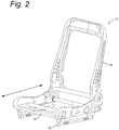
- the seat base module 12 of a modular vehicle seat system 10 in which the cushion carrier assemblies provided herein can be used includes a structural box or frame structure, made of metallic and/or plastic side members and cross members, that is adapted to be rigidly coupled to a structure (i.e., the floor) of a vehicle on a bottom side of the seat base module 12 and to a seat bottom structure module 14 on a top side of the seat base module 12.
- This seat base module 12 is not required in all modular vehicle seat system configurations - only when a degree of height is required between the associated seat bottom structure module 14 and the floor of the vehicle.
- the seat base module 12 is typically used in front seat and second row seat applications, but not in third row seat applications, or when a seat 10 is disposed on a tunnel, wheel well, or other structure of the vehicle.
- the seat bottom structure module 14 is disposed directly on the underlying vehicle structure.
- the seat base module 12 includes one of a mechanical and an electromechanical elevation mechanism adapted to vary the height of the seat bottom structure module 14 with respect to one or more of the seat base module 12 and the underlying structure of the vehicle.
- Such elevation mechanisms are well known to those of ordinary skill in the art and typically include a rotational or stepper motor coupled to an actuator mechanism, with a Hall sensor or the like used to enable seat memory functionality, for example.
- the seat base module 12 forms a discrete, unitary module, including the elevation mechanism, that can be taken off the shelf and assembled into the vehicle using any conventional attachment means, such as bolts, mechanical fasteners, and the like.
- These modules 12 can come in large and small or wide and narrow configurations, for example, provided that a limited number of "one size fits all," “off-the-shelf' options are available.
- the modules 12 provide height accommodation and/or adjustment capability and/or functionality to the modular vehicle seat system 10.
- the seat base module 12 can also be equipped with means for accommodating z-thud deformation, as appropriate.
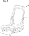
- the seat bottom structure module 14 of the modular vehicle seat system 10 is adapted to be rigidly or translatably coupled to one of the seat base module 12 and directly to the underlying structure of the vehicle on a bottom side of the seat bottom structure module 14.
- the seat bottom structure module 14 generally includes a metallic frame structure, including metallic and/or plastic side members and cross members.
- the seat base module 12 is not required in all modular vehicle seat system configurations - only when a degree of height is required between the associated seat bottom structure module 14 and the floor of the vehicle.
- the seat base module 12 is typically used in front seat and second row seat applications, but not in third row seat applications, or when a seat 10 is disposed on a tunnel, wheel well, or other structure of the vehicle.
- the seat bottom structure module 14 is disposed directly on the underlying vehicle structure.
- the seat bottom structure module 14 includes one of a mechanical and an electromechanical translation mechanism adapted to vary the forward/rearward position of the seat bottom structure module 14 with respect to one or more of the seat base module 12 and the underlying structure of the vehicle.
- Such translation mechanisms are well known to those of ordinary skill in the art and typically include a rotational or stepper motor coupled to an actuator mechanism, with a Hall sensor or the like used to enable seat memory functionality, for example.
- the seat bottom structure module 14 also forms a discrete, unitary module, including the translation mechanism, that can be taken off the shelf and assembled to the seat base module 12 using any conventional attachment means, such as bolts, mechanical fasteners, and the like.
- These modules 14 can also come in large and small or wide and narrow configurations, for example, provided that a limited number of "one size fits all," “off-the-shelf' options are available.
- the modules 14 provide width accommodation and/or translational adjustment capability and/or functionality to the modular vehicle seat system 10.
- the seat bottom structure module 14 is adapted to be securely coupled to a seat bottom cushion carrier module (not illustrated) on a top side of the seat bottom structure module 14, and rigidly or pivotably coupled to the seat back structure module 16 on one or more of a top side and a back side of the seat bottom structure module 14.
- the seat bottom structure module 14 further includes a vibration damper mechanism adapted to dampen vibration of the seat bottom structure module 14 with respect to the one of the seat base module 12 and the structure of the vehicle.
- the seat back structure module 16 of the modular vehicle seat system 10 is adapted to be rigidly or pivotably coupled to the seat bottom structure module 14 on a bottom side of the seat back structure module 16, securely coupled to a seat back cushion carrier module (not illustrated) on a front side of the seat back structure module 16, and translatably coupled to a head rest (not illustrated) on a top side of the seat back structure module 16.
- the seat back structure module 16 generally includes a metallic frame structure, including metallic and/or plastic side members and cross members.
- the seat back structure module 16 includes one of a mechanical and an electromechanical reclining and/or folding mechanism adapted to vary the reclining and/or folding angle of the seat back structure module 16 with respect to the seat bottom structure module 14.
- the seat back structure module 16 also forms a discrete, unitary module, including the reclining and/or folding mechanism, that can be taken off the shelf and assembled to the seat bottom structure module 14 using any conventional attachment means, such as bolts, mechanical fasteners, and the like.
- These modules 16 can also come in large and small or wide and narrow configurations, for example, provided that a limited number of "one size fits all," "off-the-shelf' options are available.
- the modules 16 provide width accommodation and/or reclining/folding adjustment capability and/or functionality to the modular vehicle seat system 10.
- the seat back structure module 16 is adapted to be securely coupled to a seat back cushion carrier module (not illustrated) on a front side of the seat back structure module 16, and rigidly or pivotably coupled to the seat bottom structure module 14 on one or more of a top side and a back side of the seat bottom structure module 14.
- the head rest coupled to the seat back structure module 16 can be fixed or adjustable, and can incorporate whiplash protection functionality, well known to those of ordinary skill in the art.
- An air bag module (not illustrated) can also be coupled to either or both sides of the seat back structure module 16.
- the seat back structure module 16 is configured to receive a seat back cover (not illustrated).
- the cushion carrier assemblies can be used in numerous other systems and applications as well, both modular and traditional. In this sense, the cushion carrier assemblies act as an enabling technology for the modular vehicle seat system 10 that also have much wider applicability.
- the seat bottom cushion carrier module 18 is adapted to be securely coupled to the top side of the seat bottom structure module 14 ( FIGS. 1-3 ) on a bottom side of the seat bottom cushion carrier module 18.
- the seat bottom cushion carrier module 18 includes a seat bottom cushion support member, including a metallic or plastic support frame, and a foam seat bottom cushion.
- the seat bottom cushion carrier module 18 is pre-upholstered off-the-shelf.
- the seat bottom cushion carrier module 18 is coupled to the seat bottom structure module 14 using conventional straps or the like, well known to those of ordinary skill in the art.
- the seat bottom cushion carrier module 18 includes one or more interior portions and/or surfaces for receiving functional modules (not illustrated) therein or thereon.
- the functional modules can include, but are not limited to, a tilt module operable for tilting the cushion carrier 18, an extension module operable for extending a front portion of the cushion carrier 18, a heat module, a ventilation module, an occupant detection module operable for detecting an occupant seated on the cushion carrier 18, a massage module, an integrated child safety seat module, and an armrest module.
- a tilt module operable for tilting the cushion carrier 18, an extension module operable for extending a front portion of the cushion carrier 18, a heat module, a ventilation module, an occupant detection module operable for detecting an occupant seated on the cushion carrier 18, a massage module, an integrated child safety seat module, and an armrest module.
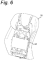
- the seat back cushion carrier module 20 is also adapted to be securely coupled to the front side of the seat back structure module 16 ( FIGS. 1-3 ) on a back side of the seat back cushion carrier module 20.
- the seat back cushion carrier module 20 includes a seat back cushion support member, including a metallic or plastic support frame, and a foam seat back cushion.
- the seat back cushion carrier module 20 is pre-upholstered off-the-shelf.
- the seat back cushion carrier module 20 is coupled to the seat back structure module 16 using conventional straps or the like, well known to those of ordinary skill in the art.
- the seat back cushion carrier module 20 includes one or more interior portions and/or surfaces for receiving functional modules (not illustrated) therein or thereon.
- the functional modules can include, but are not limited to, an extension module operable for extending side portions of the cushion carrier 20, a heat module, a ventilation module, an occupant detection module operable for detecting an occupant seated on the cushion carrier 20, a lumbar support module, a massage module, an integrated child safety seat module, and an armrest module.
- this cushion carrier 20 can also be customized with functional modules that are rapidly coupled thereto and accommodate any desired application.
- FIG. 6 illustrates an exemplary functional module 22 engaged with the seat back cushion carrier module 20. It should be noted that, ultimately, upholstery covers the seat back cushion carrier module 20 and engaged functional module 22, and any conventional electrical connections can be made from the functional module 22 to other modules and/or vehicle structures and/or systems.
- the vehicle seat 100 provided herein, whether traditional or modular in nature, generally includes a seat back frame 102 that is pivotably coupled to a seat bottom frame 104, both of which are well known to those of ordinary skill in the art.
- the seat bottom frame 104 is configured to be secured to a base structure 105 and/or a floor structure of the vehicle.
- a seat back cushion carrier assembly 106 is coupled to the seat back frame 102.
- This seat back cushion carrier assembly 106 includes a seat back carrier structure 108 to which a seat back cushion 110 is coupled.
- the seat back cushion 110 is covered with an upholstery material, such as fabric, leather, or a synthetic material, which is secured to the seat back carrier structure 108.
- the seat back frame 102 is formed from a metal or metal alloy and the seat back carrier structure 108 is formed from a plastic material.
- the seat back carrier structure 108, the seat back cushion 110, and the upholstery can be installed as a unitary modular assembly.
- a seat bottom cushion carrier assembly 112 is coupled to the seat bottom frame 104.
- This seat bottom cushion carrier assembly 112 includes a seat bottom carrier structure 114 to which a seat bottom cushion 116 is coupled.
- the seat bottom cushion 116 is also covered with an upholstery material, such as fabric, leather, or a synthetic material, which is secured to the seat bottom carrier structure 114.
- the seat bottom frame 104 is formed from a metal or metal alloy and the seat bottom carrier structure 114 is formed from a plastic material.
- the seat bottom carrier structure 114, the seat bottom cushion 116, and the upholstery can also be installed as a unitary modular assembly.
- the back of the seat 100 includes a seat back cover 118 that is coupled to the seat back frame 102 opposite the seat back cushion carrier assembly 106.
- a functional unit 120 such as a heating unit, a cooling unit, a massage unit, and/or the like, can be coupled to the seat back frame 102, the seat bottom frame 104, the seat back cushion carrier structure 108, the seat bottom cushion carrier structure 114, the seat back cushion 110, and/or the seat bottom cushion 116, underneath the associated upholstery.
- the functional unit 120 can be coupled to the seat back frame 102 or seat bottom frame 104 and affect a vehicle occupant through a port manufactured into the associated seat back carrier structure 108 or seat bottom carrier structure 114 and the associated seat back cushion 110 or seat bottom cushion 116.
- the functional unit 120 can be disposed within the seat back cushion 110 or seat bottom cushion 116.
- the seat bottom carrier structure 114 of the seat bottom carrier assembly 112 is disposed adjacent to, conformally nested into, adhered to, and/or mechanically fastened to the seat bottom cushion 116 such that the two components form a unitary component that is ultimately upholstered before it is attached to the associated seat bottom frame 104 ( FIG. 7 ).
- a plurality of strap fasteners 122 are disposed through the seat bottom cushion 116 and seat bottom carrier structure 114, securing the upholstery to the seat bottom carrier structure 114 about and through the seat bottom cushion 116, as is described in greater detail herein below.
- the seat bottom carrier structure 114 is shaped such that it conformally engages the underlying seat bottom frame 104, and the seat bottom cushion 116 is shaped such that it has a desired finished appearance that provides a safe and comfortable seating surface for the vehicle occupant. It should be noted that the seat bottom carrier structure 114 and/or seat bottom cushion 116 can define any suitable recesses or channels that provide appropriate access for a coupled or adjacent functional unit 120 ( FIG. 7 ), as described herein above.
- the seat back carrier structure 108 of the seat back carrier assembly 106 is disposed adjacent to, conformally nested into, adhered to, and/or mechanically fastened to the seat back cushion 110 such that the two components form a unitary component that is ultimately upholstered before it is attached to the associated seat back frame 102 ( FIG. 7 ).
- a plurality of strap fasteners 122 are disposed through the seat back cushion 110 and seat back carrier structure 108, securing the upholstery to the seat back carrier structure 108 about and through the seat back cushion 110, as is described in greater detail herein below.
- the seat back carrier structure 108 is shaped such that it conformally engages the underlying seat back frame 102, and the seat back cushion 110 is shaped such that it has a desired finished appearance that provides a safe and comfortable seating surface for the vehicle occupant.
- the seat back carrier structure 108 and/or seat back cushion 110 can define any suitable recesses or channels that provide appropriate access for a coupled or adjacent functional unit 120 ( FIG. 7 ), as described herein above.
- the seat back carrier structure 108 can include both attached side trim bolsters 124 and an attached top trim bolster 126, all of which affect the ultimate appearance and performance of the vehicle seat 100.
- These bolsters 124,126 can be made of a plastic material, for example, and can be attached to the seat back carrier structure 108 using screws or any other suitable type of fastener.
- the bolsters 124,126 can also be integrally formed with the seat back carrier structure 108.
- the seat bottom carrier structure 114 ( FIG. 8 ) can also include similar bolsters, if desired.
- the top trim bolster 126 includes one or more screw holes 129 through which the top trim bolster 126 is securely affixed to the seat back frame 102 ( FIG.
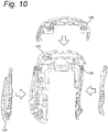
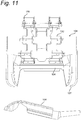
- FIG. 11 illustrates a conventional seat bottom frame/seat pan 104 to which the seat bottom cushion carrier assembly 112 ( FIG. 7 ) is ultimately coupled.
- the seat bottom carrier structure 114 ( FIG. 7 ) has a shape that substantially conforms to a front portion 127 of the seat bottom frame/seat pan 104, such that the seat bottom carrier structure 114 is guided by and nests on the seat bottom frame/seat pan 104.
- the seat bottom carrier structure also includes a plurality of hook members 128 ( FIG. 7 ) at a rear portion thereof that engage a plurality of receiver members 130 located at a rear portion of the seat bottom frame/seat pan 104.
- the majority of the seat bottom carrier structure 114 is separated from the underlying seat bottom frame/seat pan 104 by at least a few millimeters, such that the majority of the seat bottom carrier structure 114 does not actually contact the underlying seat bottom frame/seat pan 104. This prevents the seat bottom carrier structure 114 from interfering with the movement and operation of the seat bottom frame/seat pan 104.
- the majority of the seat bottom carrier structure 114 can contact the intermediate flex mat 132, which acts as a guide for and otherwise supports the seat bottom carrier structure 114. Accordingly, plugs 134 from the flex mat 132 can act as guides for the seat bottom carrier structure 114 and engage the seat bottom frame/seat pan 104.
- the strap fasteners 122 are used to fasten and tighten the upholstery 140 to the associated seat bottom cushion 116 ( FIG. 7 ) or seat back cushion 110 ( FIG. 7 ) along the desired seams, indentations, and/or design details, providing concave and convex seat surfaces.
- These strap fasteners 122 thus replace conventional hog rings and the like that are typically coupled to wires or other structures embedded in the underlying cushions 116,110.
- the strap fasteners 122 pass completely through channels provided in the foam of the cushions 116, 100 and are secured to the underlying seat bottom carrier structure 114 ( FIG. 7 ) or seat back carrier structure 108 ( FIG. 7 ).
- the strap fasteners 122 are flexible and have a degree of elasticity, typically being formed from a plastic material, and thus are easy and effective to work with. They can come in a variety of basic sizes, such that they can accommodate different thicknesses of foam.
- Each strap fastener 122 includes a strap root 142 coupled to an elongate member 144.
- the strap root 142 includes a U or V-shaped channel 146 that is open at one end and consists of a pair of opposed arms 148.
- Each arm 148 includes an inwardly protruding barb 150 or the like.
- the channel 146, via the opposed arms 148 and barbs 150, is configured to selectively engage and retain a widened plastic bead or seam 152 coupled to or disposed on a bottom/back side of the upholstery 140 being retained.
- the barbs 150 prevent the widened plastic bead or seam 152 from being pulled out of or otherwise removed from the channel 146 and strap root 142, thereby securing the strap fastener 122 to the upholstery 140. It will be readily apparent to those of ordinary skill in the art that other means for coupling the strap root 142 to the underside of the upholstery 140 could be used equally, depending upon the desired application, materials involved, etc. For example, the strap root 142 could incorporate conventional hog rings, be sewed or laminated directly to the upholstery 140, etc.
- the elongate member 144 of the strap fastener 122 is removably or fixedly coupled to, or integrally formed with, the strap root 142, such that the elongate member 144 can be used to pull on the strap root 142 and plastic bead or seam 152 and upholstery 140 held thereby.
- the elongate member 144 has a generally rectangular shape with a tapered tip 152 such that it can be pushed or pulled through holes in foam and the associated seat bottom carrier structure 114 or seat back carrier structure 108.
- the elongate member 144 includes a number of holes and channels manufactured therein, including a first locking hole 154 configured to selectively engage a locking boss manufactured on the bottom/back side of the underlying seat carrier structure 114,108 and provide a first longer effective upholstery retention length, a second locking hole 156 also configured to selectively engage the locking boss manufactured on the bottom/back side of the underlying seat carrier structure 114,108 and provide a second shorter effective upholstery retention length, and a tightening channel 158 configured to selectively translatably engage a guide boss manufactured on the bottom/back side of the underlying seat carrier structure 114,108 adjacent to the locking boss and guide the position and orientation of the elongate member 144 as it is pulled tight and locked.
- a first locking hole 154 configured to selectively engage a locking boss manufactured on the bottom/back side of the underlying seat carrier structure 114,108 and provide a first longer effective upholstery retention length
- a second locking hole 156 also configured to selectively engage the locking boss manufactured on the bottom/back side of the underlying
- the interplay of a slight eccentricity of the locking holes 154,156, the elasticity of the elongate member 144, and a slight lip manufactured onto the top of the locking boss means that the strap fastener 122 can be pulled tight, thereby pulling the upholstery 140 tight, and secured to the underlying seat carrier structure 114,108, maintaining the indentations desired in the foam and upholstery 140.
- the length of the elongate member 144 makes it easy to handle, adjust, and pull during this process, even after passing through the foam and carrier structure 114,108.
- the elongate member 144 preferably includes friction gripping surface 160 to assisting in handling, adjusting, and pulling, and a plug 162 can remain disposed in the second locking hole 156 when not used to retain the structural integrity and strength of the elongate member 144.
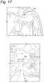
- the locking tabs 164 manufactured into/on or disposed on the various carrier structures 114,108 for receiving and retaining each strap fastener 122 ( FIG. 12 ) each include the locking boss 166 configured to be selectively engaged by the first locking hole 154 ( FIG. 12 ) or second locking hole 156 ( FIG. 12 ) of the associated elongate member 144 ( FIG. 12 ) and the guide boss 168 configured to be selectively translatably engaged by the tightening channel 158 ( FIG.
- the hole 172 in the carrier structure 114,108 through which the elongate member 144 passes is preferably angled away from the locking boss 166 and guide boss 168, thereby further serving to selectively retain and secure the elongate member 144.
- FIG. 14 highlights an exemplary arrangement of strap fasteners 122 with respect to the upholstery 140, seat back carrier structure 108, and seat bottom carrier structure 114 such that a given aesthetic design is created.
- FIG. 14 highlights an exemplary arrangement of strap fasteners 122 with respect to the upholstery 140, seat back carrier structure 108, and seat bottom carrier structure 114 such that a given aesthetic design is created.
- other configurations are possible.
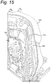
- FIG. 15 illustrates the use of clip fasteners 174 to secure upholstery 140 to the edges of a seat back carrier structure 108, which is subsequently joined to the associated seat back frame 102. It can be appreciated that, advantageously, this arrangement obviates the need to couple a side air bag module to the seat back carrier structure 108 or upholster over such side air bag module.
- the side air bag module can be coupled directly to the seat back frame 102, freeing it from any upholstery interference and enhancing manufacturing simplicity.
- any edges of the upholstery can also be conventionally secured to the seat back carrier structure 108, and seat back frame 102 in places, which is equally applicable to the seat bottom structure.
- the clip fastener 174 includes a U-shaped plastic or metal rail clip 175 around an elongate tail 176 of which the upholstery 140 to be secured is folded and stitched, fastened, adhered, or otherwise secured.
- the rail clip 175 is then pulled and disposed over an exposed edge of the associated seat carrier structure 108,114, thereby securing the upholstery around the intervening foam to the seat carrier structure 108,114.
- This replaces conventional fasteners and methodologies.
- the rail clip 175 preferably incorporates an internal barb 178 or the like that helps secure the rail clip to a corresponding recess 180 manufactured into the rail of the seat carrier structure 108,114.
- the seat carrier assemblies 106,112 can be finished as modules and/or attached to the underlying frame structures 102,104 ( FIG.7 ) using screws 182, hook-and-loop type fasteners 184, and/or any other suitable types of fasteners, all of which are contemplated by the present invention.
- the present invention provides a vehicle seat cushion carrier assembly (bottom and back) via which a cushion carrier structure, cushion foam, and upholstery are more easily assembled and installed in a vehicle, optionally as a modular unit.
- the cushion carrier structure can be multi-piece and incorporate any desired trim units.
- the cushion carrier structure also has a design and configuration that allows the cushion carrier structure to be readily and securely coupled to the underlying seat pan and/or seat frame. Strap fasteners are used to secure the upholstery to the cushion carrier structure and cushion foam, creating the desired creating seams, creases, and indentations. This replaces the use of difficult and time consuming hog rings and the like.
- Clip fasteners are used to secure the upholstery to the cushion carrier structure around the cushion foam, replacing mechanisms that secure the upholstery to the seat frame, especially with respect to the seat back. This allows much of the upholstering to be done outside the vehicle, optionally in a modular manner. Finally, these modular features and functionalities allow the cushion carrier assemblies (bottom and back) to be quickly and easily secured to the underlying seat pan and/or seat frame using simple screws, hooks, and clip fasteners.
- the cushion carrier assembly finds applicability in all types of vehicles, both traditional and autonomous driving (AD), and in both traditional and modular manufacturing and assembly processes.
Landscapes
- Engineering & Computer Science (AREA)
- Aviation & Aerospace Engineering (AREA)
- Transportation (AREA)
- Mechanical Engineering (AREA)
- Seats For Vehicles (AREA)
Applications Claiming Priority (1)
| Application Number | Priority Date | Filing Date | Title |
|---|---|---|---|
| US16/254,672 US10967772B2 (en) | 2019-01-23 | 2019-01-23 | Vehicle seat cushion carrier assembly for modular vehicle seat or the like |
Publications (2)
| Publication Number | Publication Date |
|---|---|
| EP3696014A1 true EP3696014A1 (fr) | 2020-08-19 |
| EP3696014B1 EP3696014B1 (fr) | 2022-03-09 |
Family
ID=69190680
Family Applications (1)
| Application Number | Title | Priority Date | Filing Date |
|---|---|---|---|
| EP20153374.2A Active EP3696014B1 (fr) | 2019-01-23 | 2020-01-23 | Ensemble support de coussin de siège de véhicule pour siège de véhicule modulaire ou similaire |
Country Status (3)
| Country | Link |
|---|---|
| US (1) | US10967772B2 (fr) |
| EP (1) | EP3696014B1 (fr) |
| CN (1) | CN111469730B (fr) |
Cited By (1)
| Publication number | Priority date | Publication date | Assignee | Title |
|---|---|---|---|---|
| EP4122828A1 (fr) * | 2021-07-19 | 2023-01-25 | B/E Aerospace, Inc. | Système modulaire de fixation de housse de dossier de siège d'aéronef |
Families Citing this family (2)
| Publication number | Priority date | Publication date | Assignee | Title |
|---|---|---|---|---|
| DE202019104372U1 (de) * | 2019-08-08 | 2020-11-10 | Faurecia Autositze Gmbh | Fahrzeugsitz |
| US11325515B2 (en) * | 2020-02-10 | 2022-05-10 | Lear Corporation | Seat assembly and seat portion |
Citations (7)
| Publication number | Priority date | Publication date | Assignee | Title |
|---|---|---|---|---|
| JP2004249092A (ja) * | 2003-01-30 | 2004-09-09 | Daihatsu Motor Co Ltd | 座席の暖房装置 |
| EP2705981A1 (fr) * | 2011-05-02 | 2014-03-12 | Toyota Jidosha Kabushiki Kaisha | Siège de véhicule et dossier de siège |
| WO2015067620A1 (fr) * | 2013-11-08 | 2015-05-14 | Velcro Industries B.V. | Procédé d'assujettissement de housses de garniture de siège sur des coussins de mousse |
| DE102014223955A1 (de) * | 2013-12-12 | 2015-06-18 | Lear Corporation | Sitzanordnung mit einer Bezugsanordnung |
| DE102015015700A1 (de) * | 2014-12-10 | 2016-06-16 | Ykk Corporation | Bezugsstoffbefestigungsklemme |
| US20170355291A1 (en) * | 2016-06-09 | 2017-12-14 | Ford Global Technologies, Llc | Seatback comfort carrier |
| WO2018019173A1 (fr) * | 2016-07-28 | 2018-02-01 | 周润生 | Pince de fixation pour une housse de siège de véhicule étanche à la poussière |
Family Cites Families (25)
| Publication number | Priority date | Publication date | Assignee | Title |
|---|---|---|---|---|
| US2152452A (en) * | 1935-07-06 | 1939-03-28 | Art Metal Works Inc | Pyrophoric flame producing mechanism |
| US3794378A (en) * | 1972-11-24 | 1974-02-26 | Ford Motor Co | Seat assembly |
| DE9316093U1 (de) | 1993-10-21 | 1994-08-04 | Tillner Alfred | Verankerungsleiste für einen Einzugstab zur Profilformung von Polstermaterialien |
| GB2328708B (en) | 1997-08-28 | 2000-03-29 | Leedum Limited | Attaching material to a seat |
| DE19952059A1 (de) * | 1999-10-28 | 2001-05-03 | Seibel Plastiko Ag | Befestigungselement zum Verbinden eines Polsterbezuges an einem Sitz |
| US20030151294A1 (en) | 2002-02-13 | 2003-08-14 | Glater Irving W. | Interchangeable seat cushions for automotive bucket seats |
| DE10392299T5 (de) | 2002-02-22 | 2005-02-10 | Woodbridge Foam Corp., Mississauga | Anschlussvorrichtung |
| JP4081347B2 (ja) * | 2002-10-28 | 2008-04-23 | 株式会社デルタツーリング | 座席構造 |
| JP4734549B2 (ja) * | 2004-09-29 | 2011-07-27 | テイ・エス テック株式会社 | トリムカバーの吊込み止着用クリップ |
| CA2585978A1 (fr) | 2006-12-19 | 2008-06-19 | Beverley Anne Callaghan | Mobilier a capitonnage amovible |
| US8099837B2 (en) | 2007-09-07 | 2012-01-24 | Hope Global, Division Of Nfa Corporation | Low-profile upholstery clip for attaching a bead to a foam substrate |
| JP5374859B2 (ja) * | 2007-11-07 | 2013-12-25 | トヨタ紡織株式会社 | フック部材及び表皮材の係止構造 |
| US20090152909A1 (en) | 2007-12-12 | 2009-06-18 | Lear Corporation | Attachment assembly for securing trim material to the padding of a ventilated seat |
| US7857383B2 (en) * | 2008-12-11 | 2010-12-28 | Ykk Corporation | Soft cover for covering a seat |
| US7703855B1 (en) * | 2008-12-30 | 2010-04-27 | Nissan Technical Center North America, Inc. | Vehicle seat assembly |
| EP2662238B1 (fr) | 2012-05-08 | 2021-09-29 | Volvo Car Corporation | Agencement de support de siège |
| GB2503493B (en) | 2012-06-29 | 2014-06-11 | Muir Patrick Ashworth | Shock absorption in powerboat seats |
| US8960791B2 (en) * | 2013-07-02 | 2015-02-24 | Ford Global Technologies, Llc | Trim attachment apparatus for vehicle seating assembly |
| WO2016040734A1 (fr) * | 2014-09-11 | 2016-03-17 | Faurecia Automotive Seating, Llc. | Dispositif de fixation de housse d'habillage pour un siège de véhicule |
| JP2016077681A (ja) | 2014-10-20 | 2016-05-16 | 株式会社タチエス | 面ファスナー部材およびそれを用いたシート |
| JP2016087196A (ja) * | 2014-11-07 | 2016-05-23 | トヨタ紡織株式会社 | 乗物用シート |
| JP6496125B2 (ja) * | 2014-11-10 | 2019-04-03 | 株式会社タチエス | 車両用シート |
| US9868374B2 (en) * | 2016-03-18 | 2018-01-16 | Ami Industries, Inc. | Modular monocoque backrest |
| JP7048644B2 (ja) | 2017-02-07 | 2022-04-05 | ホープ グローバル ディヴィジョン オブ エヌエフエイ コーポレイション | 装飾材リスティングのための止めクリップアセンブリ |
| DE102017212698A1 (de) * | 2017-07-25 | 2019-01-31 | Lear Corporation | Bindeanordnung für das Befestigen einer Bezugskomponente an einer Fahrzeugkomponente |
-
2019
- 2019-01-23 US US16/254,672 patent/US10967772B2/en active Active
-
2020
- 2020-01-19 CN CN202010061227.2A patent/CN111469730B/zh active Active
- 2020-01-23 EP EP20153374.2A patent/EP3696014B1/fr active Active
Patent Citations (7)
| Publication number | Priority date | Publication date | Assignee | Title |
|---|---|---|---|---|
| JP2004249092A (ja) * | 2003-01-30 | 2004-09-09 | Daihatsu Motor Co Ltd | 座席の暖房装置 |
| EP2705981A1 (fr) * | 2011-05-02 | 2014-03-12 | Toyota Jidosha Kabushiki Kaisha | Siège de véhicule et dossier de siège |
| WO2015067620A1 (fr) * | 2013-11-08 | 2015-05-14 | Velcro Industries B.V. | Procédé d'assujettissement de housses de garniture de siège sur des coussins de mousse |
| DE102014223955A1 (de) * | 2013-12-12 | 2015-06-18 | Lear Corporation | Sitzanordnung mit einer Bezugsanordnung |
| DE102015015700A1 (de) * | 2014-12-10 | 2016-06-16 | Ykk Corporation | Bezugsstoffbefestigungsklemme |
| US20170355291A1 (en) * | 2016-06-09 | 2017-12-14 | Ford Global Technologies, Llc | Seatback comfort carrier |
| WO2018019173A1 (fr) * | 2016-07-28 | 2018-02-01 | 周润生 | Pince de fixation pour une housse de siège de véhicule étanche à la poussière |
Cited By (1)
| Publication number | Priority date | Publication date | Assignee | Title |
|---|---|---|---|---|
| EP4122828A1 (fr) * | 2021-07-19 | 2023-01-25 | B/E Aerospace, Inc. | Système modulaire de fixation de housse de dossier de siège d'aéronef |
Also Published As
| Publication number | Publication date |
|---|---|
| US10967772B2 (en) | 2021-04-06 |
| EP3696014B1 (fr) | 2022-03-09 |
| CN111469730B (zh) | 2022-08-26 |
| US20200231075A1 (en) | 2020-07-23 |
| CN111469730A (zh) | 2020-07-31 |
Similar Documents
| Publication | Publication Date | Title |
|---|---|---|
| EP3696014A1 (fr) | Ensemble support de coussin de siège de véhicule pour siège de véhicule modulaire ou similaire | |
| US10232752B2 (en) | Cushion pan for a vehicle seat assembly | |
| US10011205B2 (en) | Value assembly for seatbacks and cushions | |
| US10081282B2 (en) | Inner carrier module for seatback assembly | |
| US7703855B1 (en) | Vehicle seat assembly | |
| US10166895B2 (en) | Seatback comfort carrier | |
| US20090146470A1 (en) | Vehicle seat | |
| US11787359B2 (en) | Vehicle seat | |
| US9796310B1 (en) | Composite one-piece cushion nose | |
| US10166894B2 (en) | Seatback comfort carrier | |
| EP2990260A1 (fr) | Couvercle de support latéral | |
| JP2022167380A (ja) | シート装置 | |
| CN110103792B (zh) | 用于车辆座椅的底座的装饰部件和用于制造装饰部件的方法 | |
| US20190232842A1 (en) | Seat assembly with massage feature | |
| EP3705346B1 (fr) | Sièges de véhicule modulaires | |
| CN108340818B (zh) | 椅背舒适托架 | |
| WO2018064686A9 (fr) | Appui-tête mince | |
| JP6907919B2 (ja) | 乗物用シート | |
| JPH0545536Y2 (fr) | ||
| JP2023077892A (ja) | 乗物用シート | |
| JP2000102447A (ja) | 自動車用シートのシートバック | |
| JP2023077888A (ja) | 乗物用シート | |
| JP2023077890A (ja) | 乗物用シート | |
| JP2019081545A (ja) | 乗物用シート | |
| JP2011246097A (ja) | ひざ掛け補助装置を備えた車両用シート |
Legal Events
| Date | Code | Title | Description |
|---|---|---|---|
| PUAI | Public reference made under article 153(3) epc to a published international application that has entered the european phase |
Free format text: ORIGINAL CODE: 0009012 |
|
| STAA | Information on the status of an ep patent application or granted ep patent |
Free format text: STATUS: THE APPLICATION HAS BEEN PUBLISHED |
|
| AK | Designated contracting states |
Kind code of ref document: A1 Designated state(s): AL AT BE BG CH CY CZ DE DK EE ES FI FR GB GR HR HU IE IS IT LI LT LU LV MC MK MT NL NO PL PT RO RS SE SI SK SM TR |
|
| AX | Request for extension of the european patent |
Extension state: BA ME |
|
| STAA | Information on the status of an ep patent application or granted ep patent |
Free format text: STATUS: REQUEST FOR EXAMINATION WAS MADE |
|
| 17P | Request for examination filed |
Effective date: 20210219 |
|
| RBV | Designated contracting states (corrected) |
Designated state(s): AL AT BE BG CH CY CZ DE DK EE ES FI FR GB GR HR HU IE IS IT LI LT LU LV MC MK MT NL NO PL PT RO RS SE SI SK SM TR |
|
| RIC1 | Information provided on ipc code assigned before grant |
Ipc: B60N 2/70 20060101AFI20210622BHEP Ipc: B60N 2/58 20060101ALI20210622BHEP |
|
| GRAP | Despatch of communication of intention to grant a patent |
Free format text: ORIGINAL CODE: EPIDOSNIGR1 |
|
| STAA | Information on the status of an ep patent application or granted ep patent |
Free format text: STATUS: GRANT OF PATENT IS INTENDED |
|
| INTG | Intention to grant announced |
Effective date: 20210812 |
|
| GRAS | Grant fee paid |
Free format text: ORIGINAL CODE: EPIDOSNIGR3 |
|
| GRAA | (expected) grant |
Free format text: ORIGINAL CODE: 0009210 |
|
| STAA | Information on the status of an ep patent application or granted ep patent |
Free format text: STATUS: THE PATENT HAS BEEN GRANTED |
|
| AK | Designated contracting states |
Kind code of ref document: B1 Designated state(s): AL AT BE BG CH CY CZ DE DK EE ES FI FR GB GR HR HU IE IS IT LI LT LU LV MC MK MT NL NO PL PT RO RS SE SI SK SM TR |
|
| REG | Reference to a national code |
Ref country code: CH Ref legal event code: EP Ref country code: AT Ref legal event code: REF Ref document number: 1473865 Country of ref document: AT Kind code of ref document: T Effective date: 20220315 |
|
| REG | Reference to a national code |
Ref country code: IE Ref legal event code: FG4D |
|
| REG | Reference to a national code |
Ref country code: DE Ref legal event code: R096 Ref document number: 602020002082 Country of ref document: DE |
|
| REG | Reference to a national code |
Ref country code: SE Ref legal event code: TRGR |
|
| REG | Reference to a national code |
Ref country code: LT Ref legal event code: MG9D |
|
| REG | Reference to a national code |
Ref country code: NL Ref legal event code: MP Effective date: 20220309 |
|
| PG25 | Lapsed in a contracting state [announced via postgrant information from national office to epo] |
Ref country code: RS Free format text: LAPSE BECAUSE OF FAILURE TO SUBMIT A TRANSLATION OF THE DESCRIPTION OR TO PAY THE FEE WITHIN THE PRESCRIBED TIME-LIMIT Effective date: 20220309 Ref country code: NO Free format text: LAPSE BECAUSE OF FAILURE TO SUBMIT A TRANSLATION OF THE DESCRIPTION OR TO PAY THE FEE WITHIN THE PRESCRIBED TIME-LIMIT Effective date: 20220609 Ref country code: LT Free format text: LAPSE BECAUSE OF FAILURE TO SUBMIT A TRANSLATION OF THE DESCRIPTION OR TO PAY THE FEE WITHIN THE PRESCRIBED TIME-LIMIT Effective date: 20220309 Ref country code: HR Free format text: LAPSE BECAUSE OF FAILURE TO SUBMIT A TRANSLATION OF THE DESCRIPTION OR TO PAY THE FEE WITHIN THE PRESCRIBED TIME-LIMIT Effective date: 20220309 Ref country code: BG Free format text: LAPSE BECAUSE OF FAILURE TO SUBMIT A TRANSLATION OF THE DESCRIPTION OR TO PAY THE FEE WITHIN THE PRESCRIBED TIME-LIMIT Effective date: 20220609 |
|
| REG | Reference to a national code |
Ref country code: AT Ref legal event code: MK05 Ref document number: 1473865 Country of ref document: AT Kind code of ref document: T Effective date: 20220309 |
|
| PG25 | Lapsed in a contracting state [announced via postgrant information from national office to epo] |
Ref country code: LV Free format text: LAPSE BECAUSE OF FAILURE TO SUBMIT A TRANSLATION OF THE DESCRIPTION OR TO PAY THE FEE WITHIN THE PRESCRIBED TIME-LIMIT Effective date: 20220309 Ref country code: GR Free format text: LAPSE BECAUSE OF FAILURE TO SUBMIT A TRANSLATION OF THE DESCRIPTION OR TO PAY THE FEE WITHIN THE PRESCRIBED TIME-LIMIT Effective date: 20220610 Ref country code: FI Free format text: LAPSE BECAUSE OF FAILURE TO SUBMIT A TRANSLATION OF THE DESCRIPTION OR TO PAY THE FEE WITHIN THE PRESCRIBED TIME-LIMIT Effective date: 20220309 |
|
| PG25 | Lapsed in a contracting state [announced via postgrant information from national office to epo] |
Ref country code: NL Free format text: LAPSE BECAUSE OF FAILURE TO SUBMIT A TRANSLATION OF THE DESCRIPTION OR TO PAY THE FEE WITHIN THE PRESCRIBED TIME-LIMIT Effective date: 20220309 |
|
| PG25 | Lapsed in a contracting state [announced via postgrant information from national office to epo] |
Ref country code: SM Free format text: LAPSE BECAUSE OF FAILURE TO SUBMIT A TRANSLATION OF THE DESCRIPTION OR TO PAY THE FEE WITHIN THE PRESCRIBED TIME-LIMIT Effective date: 20220309 Ref country code: SK Free format text: LAPSE BECAUSE OF FAILURE TO SUBMIT A TRANSLATION OF THE DESCRIPTION OR TO PAY THE FEE WITHIN THE PRESCRIBED TIME-LIMIT Effective date: 20220309 Ref country code: RO Free format text: LAPSE BECAUSE OF FAILURE TO SUBMIT A TRANSLATION OF THE DESCRIPTION OR TO PAY THE FEE WITHIN THE PRESCRIBED TIME-LIMIT Effective date: 20220309 Ref country code: PT Free format text: LAPSE BECAUSE OF FAILURE TO SUBMIT A TRANSLATION OF THE DESCRIPTION OR TO PAY THE FEE WITHIN THE PRESCRIBED TIME-LIMIT Effective date: 20220711 Ref country code: ES Free format text: LAPSE BECAUSE OF FAILURE TO SUBMIT A TRANSLATION OF THE DESCRIPTION OR TO PAY THE FEE WITHIN THE PRESCRIBED TIME-LIMIT Effective date: 20220309 Ref country code: EE Free format text: LAPSE BECAUSE OF FAILURE TO SUBMIT A TRANSLATION OF THE DESCRIPTION OR TO PAY THE FEE WITHIN THE PRESCRIBED TIME-LIMIT Effective date: 20220309 Ref country code: CZ Free format text: LAPSE BECAUSE OF FAILURE TO SUBMIT A TRANSLATION OF THE DESCRIPTION OR TO PAY THE FEE WITHIN THE PRESCRIBED TIME-LIMIT Effective date: 20220309 Ref country code: AT Free format text: LAPSE BECAUSE OF FAILURE TO SUBMIT A TRANSLATION OF THE DESCRIPTION OR TO PAY THE FEE WITHIN THE PRESCRIBED TIME-LIMIT Effective date: 20220309 |
|
| PG25 | Lapsed in a contracting state [announced via postgrant information from national office to epo] |
Ref country code: PL Free format text: LAPSE BECAUSE OF FAILURE TO SUBMIT A TRANSLATION OF THE DESCRIPTION OR TO PAY THE FEE WITHIN THE PRESCRIBED TIME-LIMIT Effective date: 20220309 Ref country code: IS Free format text: LAPSE BECAUSE OF FAILURE TO SUBMIT A TRANSLATION OF THE DESCRIPTION OR TO PAY THE FEE WITHIN THE PRESCRIBED TIME-LIMIT Effective date: 20220709 Ref country code: AL Free format text: LAPSE BECAUSE OF FAILURE TO SUBMIT A TRANSLATION OF THE DESCRIPTION OR TO PAY THE FEE WITHIN THE PRESCRIBED TIME-LIMIT Effective date: 20220309 |
|
| REG | Reference to a national code |
Ref country code: DE Ref legal event code: R097 Ref document number: 602020002082 Country of ref document: DE |
|
| PLBE | No opposition filed within time limit |
Free format text: ORIGINAL CODE: 0009261 |
|
| STAA | Information on the status of an ep patent application or granted ep patent |
Free format text: STATUS: NO OPPOSITION FILED WITHIN TIME LIMIT |
|
| PG25 | Lapsed in a contracting state [announced via postgrant information from national office to epo] |
Ref country code: DK Free format text: LAPSE BECAUSE OF FAILURE TO SUBMIT A TRANSLATION OF THE DESCRIPTION OR TO PAY THE FEE WITHIN THE PRESCRIBED TIME-LIMIT Effective date: 20220309 |
|
| 26N | No opposition filed |
Effective date: 20221212 |
|
| PG25 | Lapsed in a contracting state [announced via postgrant information from national office to epo] |
Ref country code: SI Free format text: LAPSE BECAUSE OF FAILURE TO SUBMIT A TRANSLATION OF THE DESCRIPTION OR TO PAY THE FEE WITHIN THE PRESCRIBED TIME-LIMIT Effective date: 20220309 |
|
| PGFP | Annual fee paid to national office [announced via postgrant information from national office to epo] |
Ref country code: SE Payment date: 20230124 Year of fee payment: 4 |
|
| PG25 | Lapsed in a contracting state [announced via postgrant information from national office to epo] |
Ref country code: IT Free format text: LAPSE BECAUSE OF FAILURE TO SUBMIT A TRANSLATION OF THE DESCRIPTION OR TO PAY THE FEE WITHIN THE PRESCRIBED TIME-LIMIT Effective date: 20220309 |
|
| REG | Reference to a national code |
Ref country code: CH Ref legal event code: PL |
|
| PG25 | Lapsed in a contracting state [announced via postgrant information from national office to epo] |
Ref country code: LU Free format text: LAPSE BECAUSE OF NON-PAYMENT OF DUE FEES Effective date: 20230123 |
|
| REG | Reference to a national code |
Ref country code: BE Ref legal event code: MM Effective date: 20230131 |
|
| PG25 | Lapsed in a contracting state [announced via postgrant information from national office to epo] |
Ref country code: LI Free format text: LAPSE BECAUSE OF NON-PAYMENT OF DUE FEES Effective date: 20230131 Ref country code: CH Free format text: LAPSE BECAUSE OF NON-PAYMENT OF DUE FEES Effective date: 20230131 |
|
| PG25 | Lapsed in a contracting state [announced via postgrant information from national office to epo] |
Ref country code: FR Free format text: LAPSE BECAUSE OF NON-PAYMENT OF DUE FEES Effective date: 20230131 Ref country code: BE Free format text: LAPSE BECAUSE OF NON-PAYMENT OF DUE FEES Effective date: 20230131 |
|
| P01 | Opt-out of the competence of the unified patent court (upc) registered |
Effective date: 20231212 |
|
| PG25 | Lapsed in a contracting state [announced via postgrant information from national office to epo] |
Ref country code: IE Free format text: LAPSE BECAUSE OF NON-PAYMENT OF DUE FEES Effective date: 20230123 |
|
| PGFP | Annual fee paid to national office [announced via postgrant information from national office to epo] |
Ref country code: DE Payment date: 20231219 Year of fee payment: 5 |